WO2024142504A1 - 補助工具および補助工具付きコネクタ - Google Patents
補助工具および補助工具付きコネクタ Download PDFInfo
- Publication number
- WO2024142504A1 WO2024142504A1 PCT/JP2023/033330 JP2023033330W WO2024142504A1 WO 2024142504 A1 WO2024142504 A1 WO 2024142504A1 JP 2023033330 W JP2023033330 W JP 2023033330W WO 2024142504 A1 WO2024142504 A1 WO 2024142504A1
- Authority
- WO
- WIPO (PCT)
- Prior art keywords
- housing
- auxiliary tool
- connector
- connectors
- adapter
- Prior art date
- Legal status (The legal status is an assumption and is not a legal conclusion. Google has not performed a legal analysis and makes no representation as to the accuracy of the status listed.)
- Ceased
Links
Images




Classifications
-
- G—PHYSICS
- G02—OPTICS
- G02B—OPTICAL ELEMENTS, SYSTEMS OR APPARATUS
- G02B6/00—Light guides; Structural details of arrangements comprising light guides and other optical elements, e.g. couplings
- G02B6/24—Coupling light guides
- G02B6/36—Mechanical coupling means
-
- G—PHYSICS
- G02—OPTICS
- G02B—OPTICAL ELEMENTS, SYSTEMS OR APPARATUS
- G02B6/00—Light guides; Structural details of arrangements comprising light guides and other optical elements, e.g. couplings
- G02B6/24—Coupling light guides
- G02B6/36—Mechanical coupling means
- G02B6/40—Mechanical coupling means having fibre bundle mating means
Definitions
- the present invention relates to an auxiliary tool and a connector with an auxiliary tool.
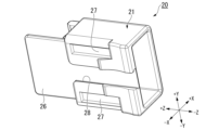
- aspect 1 of the present invention is an auxiliary tool for connecting multiple connectors having optical fibers to an adapter, comprising a first housing and a second housing, the first housing having a first opening for projecting the multiple connectors toward the adapter and a second opening facing the second housing, the second housing having multiple pressing parts that enter the inside of the first housing from the second opening and press the multiple connectors, and the inside of the first housing is provided with multiple release parts that respectively come into contact with the multiple connectors when the first housing moves away from the adapter.
- the above aspects of the present invention provide an auxiliary tool and a connector with an auxiliary tool that can connect and disconnect multiple connectors at the same time.
- FIG. 4 is a cross-sectional view taken along the line IV-IV in FIG. 1.
- the connector 100 has a plurality of optical fibers 101.
- the ferrule 110 has a plurality of fiber holes 111.
- the optical fibers 101 are inserted into these fiber holes 111.
- the optical fibers 101 have a glass portion and a coating layer that covers the glass portion. In the example of FIG. 4, the glass portion is inserted into the fiber hole 111.
- a biasing member 113 that biases the ferrule 110 is disposed inside the housing 120.
- the biasing member 113 is, for example, a coil spring.
- the ferrule 110 has a connection end surface 112 from which the optical fiber 101 is exposed. The biasing force of the biasing member 113 causes the connection end surface 112 to abut against the connection end surface of another connector inside the adapter 3. This optically connects the two connectors.
- the movable member 140b is movable in the longitudinal direction Z relative to the boot body 140a within the range of the gap G shown in FIG. 4. This configuration prevents the force from being directly transmitted to the elastic piece 130 when the optical cord is pulled or bent. This prevents the engagement protrusion 131 from coming off the engagement hole 3c, i.e., prevents the connector 100 from being disengaged from the adapter 3.
- the guide protrusion 17 fits into the inside of the guide recess 28.
- the two locking protrusions 16 fit into the two locking recesses 27.
- the width of the guide protrusion 17 and the guide recess 28 in the left-right direction Y increases toward the upper side. This prevents the guide protrusion 17 from falling off the guide recess 28 to the lower side.
- the relative positions of the first housing 10 and the second housing 20 in the up-down direction X are determined. In this state, the first housing 10 and the second housing 20 can move relative to each other in the longitudinal direction Z. During the relative movement, the guide protrusion 17 slides against the guide recess 28, and the locking protrusion 16 slides against the locking recess 27.
- the two locking recesses 27 of the second housing 20 have a shape in which both ends in the longitudinal direction Z are closed. Therefore, if the first housing 10 and the second housing 20 are moved relative to each other beyond the range of the length of the locking recesses 27 in the longitudinal direction Z, the locking protrusions 16 come into contact with the ends of the locking recesses 27. That is, the locking protrusions 16 and the locking recesses 27 restrict the relative movement of the first housing 10 and the second housing 20 in the longitudinal direction Z within a certain range. In this way, the locking protrusions 16 and the locking recesses 27 have the function of maintaining the first housing 10 and the second housing 20 in a combined state. However, it is also possible to separate the first housing 10 and the second housing 20 by, for example, elastically deforming the locking protrusions 16 downward to release the locking of the locking recesses 27.
- the first housing 10 is formed with the same number of avoidance holes 15 as the connectors 100 (four in this embodiment).
- Each avoidance hole 15 penetrates the upper wall (the wall portion facing upward) of the first main body portion 10a in the vertical direction X.
- These avoidance holes 15 are arranged at intervals in the left-right direction Y.
- FIG. 7 is a cross-sectional arrow view taken along line VII-VII in FIG. 6.
- release portions 14a to 14d are formed (provided) with the same number as the connectors 100 (four in this embodiment).
- the release portions 14a to 14d have the function of releasing the connection of the connector 100 to the adapter 3.
- the pressing pieces 22-25 enter the first main body 10a toward the tip side.
- the third pressing part 24a located furthest from the tip side is the first to abut against the first abutment surface 141 of the connector 100.
- the first pressing part 22a, the second pressing part 23a, and the fourth pressing part 25a are separated from the first abutment surface 141 of each connector 100. In other words, only the single third pressing part 24a presses the connector 100 toward the tip side.
- the engaging protrusion 131 of the connector 100 engages with the engaging hole 3c of the adapter 3. This completes the connection between the connector 100 and the adapter 3.
- the user continues to press the second housing 20 toward the adapter 3.
- This causes the second pressing portion 23a, which is the second-most distal one of the multiple pressing portions 22a to 25a, to abut against the first abutment surface 141 of the connector 100.
- the engaging protrusion 131 engages with the engaging hole 3c.
- the fourth release portion 14d which is located second to the base end, abuts against the second abutment surface 142 of the corresponding connector 100.
- the fourth release portion 14d then pushes the connector 100 toward the base end, thereby disconnecting the connector 100. Thereafter, the remaining connectors 100 are sequentially disconnected from the adapter 3.
- the four connectors 100 can be disconnected from the adapter 3 all at once by a single operation of pulling the first housing 10.
- the four connectors 100 are to be disconnected simultaneously, the operating force required is four times or more greater than the operating force required to disconnect one connector 100.
- the multiple release portions 14a to 14d disconnect each connector 100 at different times. Therefore, the operating force required for the bulk disconnection operation is reduced.
- ⁇ Individual disconnection work> For example, in a maintenance operation or the like, only some of the multiple connectors 100 may be disconnected from the adapter 3.
- the method of operating the auxiliary tool 1 in such a case will be described.
- the second housing 20 is pulled toward the base end relative to the first housing 10.
- the locking protrusion 16 of the first housing 10 abuts against the end of the locking recess 27 of the second housing 20, so that the movement of the second housing 20 toward the base end is restricted.
- the locking protrusion 16 is elastically deformed downward to release the locking of the locking recess 27. This allows the second housing 20 to move further toward the base end.
Landscapes
- Physics & Mathematics (AREA)
- General Physics & Mathematics (AREA)
- Optics & Photonics (AREA)
- Manufacturing Of Electrical Connectors (AREA)
- Mechanical Coupling Of Light Guides (AREA)
- Connector Housings Or Holding Contact Members (AREA)
Priority Applications (3)
| Application Number | Priority Date | Filing Date | Title |
|---|---|---|---|
| PCT/JP2023/045462 WO2024143066A1 (ja) | 2022-12-27 | 2023-12-19 | 補助工具および補助工具付きコネクタ |
| CN202380087515.7A CN120457371A (zh) | 2022-12-27 | 2023-12-19 | 辅助工具以及带辅助工具的连接器 |
| JP2024567654A JPWO2024143066A1 (https=) | 2022-12-27 | 2023-12-19 |
Applications Claiming Priority (2)
| Application Number | Priority Date | Filing Date | Title |
|---|---|---|---|
| JP2022210274 | 2022-12-27 | ||
| JP2022-210274 | 2022-12-27 |
Publications (1)
| Publication Number | Publication Date |
|---|---|
| WO2024142504A1 true WO2024142504A1 (ja) | 2024-07-04 |
Family
ID=91717214
Family Applications (2)
| Application Number | Title | Priority Date | Filing Date |
|---|---|---|---|
| PCT/JP2023/033330 Ceased WO2024142504A1 (ja) | 2022-12-27 | 2023-09-13 | 補助工具および補助工具付きコネクタ |
| PCT/JP2023/045462 Ceased WO2024143066A1 (ja) | 2022-12-27 | 2023-12-19 | 補助工具および補助工具付きコネクタ |
Family Applications After (1)
| Application Number | Title | Priority Date | Filing Date |
|---|---|---|---|
| PCT/JP2023/045462 Ceased WO2024143066A1 (ja) | 2022-12-27 | 2023-12-19 | 補助工具および補助工具付きコネクタ |
Country Status (3)
| Country | Link |
|---|---|
| JP (1) | JPWO2024143066A1 (https=) |
| CN (1) | CN120457371A (https=) |
| WO (2) | WO2024142504A1 (https=) |
Citations (4)
| Publication number | Priority date | Publication date | Assignee | Title |
|---|---|---|---|---|
| JP2015060126A (ja) * | 2013-09-19 | 2015-03-30 | 株式会社フジクラ | 中継用光接続ユニット |
| JP2015215381A (ja) * | 2014-05-07 | 2015-12-03 | 株式会社フジクラ | 中継用光接続ユニット |
| US10725252B1 (en) * | 2019-07-03 | 2020-07-28 | Hewlett Packard Enterprise Development Lp | Modular optical ferrule adapter and carrier systems for customizable optical connectivity and having moveable ferrule carriers |
| US20200284998A1 (en) * | 2017-12-19 | 2020-09-10 | US Conec, Ltd | Mini duplex connector with push-pull polarity mechanism and carrier |
Family Cites Families (2)
| Publication number | Priority date | Publication date | Assignee | Title |
|---|---|---|---|---|
| JP5439319B2 (ja) * | 2010-09-06 | 2014-03-12 | 株式会社フジクラ | 光コネクタおよび光コネクタの挿抜方法 |
| JP7208623B2 (ja) * | 2019-03-04 | 2023-01-19 | 株式会社精工技研 | プラグ用工具及びプラグ並びにプラグ付きケーブル |
-
2023
- 2023-09-13 WO PCT/JP2023/033330 patent/WO2024142504A1/ja not_active Ceased
- 2023-12-19 JP JP2024567654A patent/JPWO2024143066A1/ja active Pending
- 2023-12-19 WO PCT/JP2023/045462 patent/WO2024143066A1/ja not_active Ceased
- 2023-12-19 CN CN202380087515.7A patent/CN120457371A/zh active Pending
Patent Citations (4)
| Publication number | Priority date | Publication date | Assignee | Title |
|---|---|---|---|---|
| JP2015060126A (ja) * | 2013-09-19 | 2015-03-30 | 株式会社フジクラ | 中継用光接続ユニット |
| JP2015215381A (ja) * | 2014-05-07 | 2015-12-03 | 株式会社フジクラ | 中継用光接続ユニット |
| US20200284998A1 (en) * | 2017-12-19 | 2020-09-10 | US Conec, Ltd | Mini duplex connector with push-pull polarity mechanism and carrier |
| US10725252B1 (en) * | 2019-07-03 | 2020-07-28 | Hewlett Packard Enterprise Development Lp | Modular optical ferrule adapter and carrier systems for customizable optical connectivity and having moveable ferrule carriers |
Also Published As
| Publication number | Publication date |
|---|---|
| WO2024143066A1 (ja) | 2024-07-04 |
| JPWO2024143066A1 (https=) | 2024-07-04 |
| CN120457371A (zh) | 2025-08-08 |
Similar Documents
| Publication | Publication Date | Title |
|---|---|---|
| US7052186B1 (en) | Secondary latch sleeve for connector connections | |
| CN110412697B (zh) | 模块化连接器和适配器设备 | |
| US8740473B2 (en) | Optical connector and connector connection system | |
| CN110249248B (zh) | 具有可逆极性的光学连接器 | |
| US10598870B2 (en) | Fiber optic connector with dual multi-fiber ferrules, and cable assemblies and systems including the same | |
| JP5416088B2 (ja) | コネクタユニット | |
| US10191227B2 (en) | Fiber optic connector with small profile, and cable assemblies, systems, and methods including the same | |
| CN107193087B (zh) | 光纤连接器以及包括其的电缆组件、系统和方法 | |
| US4762389A (en) | Optical fiber connector | |
| CN208125956U (zh) | 光纤连接器和光纤电缆组件 | |
| CA2662854C (en) | Optical connector | |
| US8770859B2 (en) | Optical adapter | |
| EP2144100B1 (en) | Optical Connector Plug | |
| CA2722495A1 (en) | Optical connector and insertion and removal method of optical connector | |
| JP5059068B2 (ja) | 着脱工具 | |
| EP4314918B1 (en) | Ferrule holder for miniature mt ferrule and adapter interface for mating with fiber optic connectors | |
| JP5622476B2 (ja) | 光コネクタ、コネクタ接続システム | |
| WO2024142504A1 (ja) | 補助工具および補助工具付きコネクタ | |
| JP2005062513A (ja) | 光コネクタ | |
| WO2025134463A1 (ja) | 補助工具 | |
| JP4728917B2 (ja) | 光コネクタ | |
| JPH0590410U (ja) | 光コネクタ用のプラグ |
Legal Events
| Date | Code | Title | Description |
|---|---|---|---|
| 121 | Ep: the epo has been informed by wipo that ep was designated in this application |
Ref document number: 23911288 Country of ref document: EP Kind code of ref document: A1 |
|
| NENP | Non-entry into the national phase |
Ref country code: DE |
|
| 122 | Ep: pct application non-entry in european phase |
Ref document number: 23911288 Country of ref document: EP Kind code of ref document: A1 |
|
| NENP | Non-entry into the national phase |
Ref country code: JP |