WO2024142307A1 - Work device - Google Patents
Work device Download PDFInfo
- Publication number
- WO2024142307A1 WO2024142307A1 PCT/JP2022/048351 JP2022048351W WO2024142307A1 WO 2024142307 A1 WO2024142307 A1 WO 2024142307A1 JP 2022048351 W JP2022048351 W JP 2022048351W WO 2024142307 A1 WO2024142307 A1 WO 2024142307A1
- Authority
- WO
- WIPO (PCT)
- Prior art keywords
- support members
- grass cutter
- aircraft
- adjustment mechanism
- working device
- Prior art date
Links
- 230000007246 mechanism Effects 0.000 claims abstract description 64
- 238000001514 detection method Methods 0.000 claims description 32
- 230000005484 gravity Effects 0.000 claims description 6
- 238000000926 separation method Methods 0.000 claims description 6
- 238000004804 winding Methods 0.000 claims description 5
- 244000025254 Cannabis sativa Species 0.000 description 96
- 238000004891 communication Methods 0.000 description 14
- 230000008859 change Effects 0.000 description 9
- 230000010355 oscillation Effects 0.000 description 8
- 230000001133 acceleration Effects 0.000 description 6
- 230000005611 electricity Effects 0.000 description 6
- 230000007423 decrease Effects 0.000 description 3
- 238000012545 processing Methods 0.000 description 3
- 230000004043 responsiveness Effects 0.000 description 3
- 239000000725 suspension Substances 0.000 description 3
- 230000004048 modification Effects 0.000 description 2
- 238000012986 modification Methods 0.000 description 2
- RZVHIXYEVGDQDX-UHFFFAOYSA-N 9,10-anthraquinone Chemical group C1=CC=C2C(=O)C3=CC=CC=C3C(=O)C2=C1 RZVHIXYEVGDQDX-UHFFFAOYSA-N 0.000 description 1
- 230000001174 ascending effect Effects 0.000 description 1
- 238000010276 construction Methods 0.000 description 1
- 238000012937 correction Methods 0.000 description 1
- 230000003247 decreasing effect Effects 0.000 description 1
- 238000010586 diagram Methods 0.000 description 1
- 239000000446 fuel Substances 0.000 description 1
- 208000018883 loss of balance Diseases 0.000 description 1
- 239000002184 metal Substances 0.000 description 1
- 238000000034 method Methods 0.000 description 1
- 239000000575 pesticide Substances 0.000 description 1
- 230000008569 process Effects 0.000 description 1
- 238000005507 spraying Methods 0.000 description 1
Images


Classifications
-
- B—PERFORMING OPERATIONS; TRANSPORTING
- B64—AIRCRAFT; AVIATION; COSMONAUTICS
- B64C—AEROPLANES; HELICOPTERS
- B64C39/00—Aircraft not otherwise provided for
- B64C39/02—Aircraft not otherwise provided for characterised by special use
-
- B—PERFORMING OPERATIONS; TRANSPORTING
- B64—AIRCRAFT; AVIATION; COSMONAUTICS
- B64U—UNMANNED AERIAL VEHICLES [UAV]; EQUIPMENT THEREFOR
- B64U80/00—Transport or storage specially adapted for UAVs
- B64U80/80—Transport or storage specially adapted for UAVs by vehicles
- B64U80/82—Airborne vehicles
Definitions
- the satellite positioning device 34 receives GNSS (Global Navigation Satellite System) signals from artificial satellites, obtains positioning data indicating the position of the grass cutter 3 based on the received signals, and transmits the data to the grass cutter control device 33.
- GNSS Global Navigation Satellite System
- GPS, QZSS, Galileo, GLONASS, BeiDou, etc. can be used as the GNSS.
- the rocking can be quickly canceled when the weight is small, and the extension speed of the support member 41 is decreased and/or the responsiveness is slowed when the weight is large, thereby avoiding a situation in which a sudden inertial force is applied to the grass cutter 3 and the working device 4 becomes uncontrollable.
- stable work is possible simply by extending and retracting the support member 41 (wire 41b), and thus the inconvenience of not being able to transport the grass cutter 3 to the destination and not being able to start work can be easily eliminated.
- the winch 41a of the support member 41 is provided on the aircraft 2 side, but the winch 41a may be provided on the grass cutter 3 side, and the grass cutter 3 may be suspended by the support member 40b and wire 41b that pass through the aircraft 2 side.
Landscapes
- Engineering & Computer Science (AREA)
- Aviation & Aerospace Engineering (AREA)
- Mechanical Engineering (AREA)
- Remote Sensing (AREA)
- Transportation (AREA)
- Load-Engaging Elements For Cranes (AREA)
Abstract
Provided is a work device capable of performing work stably without detaching an object. A work device (4) that suspends an object (3) comprises: a plurality of support members (41) for suspending and supporting the object (3); an adjustment mechanism (42a) for adjusting the attitude of the plurality of support members (41); and a control unit (43) for controlling the operation of at least the adjustment mechanism (42a). Each support member (41) is connected to a corner portion of the object (3).
Description
本発明は、飛行体等に接続可能な作業装置に関する。
The present invention relates to a work device that can be connected to an aircraft, etc.
近年、ドローン等の飛行体を用いて荷物(対象物)を運搬したり、作業機(対象物)を移動させたりするための作業装置が検討されている。特許文献1には、荷物を吊り下げるワイヤーロープを巻き取り可能なウインチ機構を備えたドローンが開示されている。
In recent years, work devices that use drones and other flying objects to transport cargo (objects) or move work equipment (objects) have been considered. Patent Document 1 discloses a drone equipped with a winch mechanism that can wind up a wire rope that suspends cargo.
特許文献1に記載の作業装置は、機体の姿勢や速度を制御する飛行制御部と、機体の飛行状態に基づいて荷物の締結を解除する締結解除部とを備えている。締結解除部は、ドローンの飛行が不安定である場合、ワイヤーロープを切刃により切断して荷物の締結を解除する。これにより、ドローンを軽量化して安全な飛行を維持するものである。
The work device described in Patent Document 1 is equipped with a flight control unit that controls the attitude and speed of the aircraft, and a fastening release unit that releases the fastening of the load based on the flight state of the aircraft. If the drone's flight is unstable, the fastening release unit cuts the wire rope with a cutting blade to release the fastening of the load. This reduces the drone's weight and maintains safe flight.
特許文献1に記載の作業装置は、ドローンの飛行を安定させるために対象物を切り離しているため、対象物を目的地まで運搬できず、作業が開始できないといった不都合があった。しかも、切り離された対象物を回収するのに手間がかかる。
The work device described in Patent Document 1 detaches the target object to stabilize the drone's flight, which causes the problem that the target object cannot be transported to the destination and work cannot be started. Moreover, it takes time and effort to retrieve the detached target object.
そこで、対象物を切り離すことなく安定的に作業可能な作業装置が求められる。
Therefore, there is a need for a work device that can perform work stably without detaching the target object.
本発明に係る作業装置は、対象物を吊り下げる作業装置であって、前記対象物を吊り下げ支持する複数の支持部材と、複数の前記支持部材の姿勢を調節する調節機構と、少なくとも前記調節機構の作動を制御する制御部と、を備え、それぞれの前記支持部材は、前記対象物の角部に接続されていることを特徴とする。
The working device according to the present invention is a working device for suspending an object, and is characterized in that it comprises a plurality of support members for suspending and supporting the object, an adjustment mechanism for adjusting the attitude of the plurality of support members, and a control unit for controlling the operation of at least the adjustment mechanism, and each of the support members is connected to a corner of the object.
この構成によれば、調節機構により複数の支持部材の姿勢を変更させて対象物の揺動を打ち消すことが可能となるため、例えば飛行体に作業装置を装着した場合であっても、安定的な作業を実施できる。また、それぞれの支持部材は揺動モーメントが大きくなる対象物の角部に接続されているため、対象物が様々な方向に揺動した場合でも、対象物の姿勢を状況に応じて安定化することが可能となり、対象物を目的地まで運搬できず、作業が開始できないといった不都合を簡便に解消できる。なお、対象物は、荷物や草刈機といった作業機等を含む概念である。
With this configuration, the adjustment mechanism can change the attitude of the multiple support members to counteract the swaying of the object, allowing stable work to be carried out even when, for example, a work device is attached to an aircraft. In addition, because each support member is connected to a corner of the object where the swaying moment is large, even if the object sways in various directions, it is possible to stabilize the object's attitude according to the situation, easily resolving inconveniences such as the object not being able to be transported to the destination and work not being able to be started. Note that the concept of object includes luggage, work machines such as lawnmowers, etc.
以下、本発明の好適な態様について説明する。ただし、以下に記載する好適な態様例によって、本発明の範囲が限定されるわけではない。
The following describes preferred embodiments of the present invention. However, the scope of the present invention is not limited to the preferred embodiments described below.
本発明に係る作業装置は、一態様として、複数の前記支持部材による支持荷重は、前記対象物の重量以上であることが好ましい。
In one embodiment of the working device according to the present invention, the load supported by the multiple support members is preferably equal to or greater than the weight of the object.
この構成によれば、複数の支持部材は対象物の重量以上の支持荷重があるため、対象物が落下するといった不都合を防止できる。
With this configuration, the multiple support members have a supporting load that is greater than the weight of the object, preventing problems such as the object falling.
本発明に係る作業装置は、一態様として、前記制御部は、複数の前記支持部材による支持中心が前記対象物の重心位置となるように前記調節機構を制御することが好ましい。
In one aspect of the working device according to the present invention, the control unit preferably controls the adjustment mechanism so that the support center of the multiple support members coincides with the center of gravity of the target object.
この構成のように、複数の支持部材の支持中心が対象物の重心位置となるように制御すれば、対象物の揺動によりバランスが崩れるといった不都合を防止できる。
With this configuration, by controlling the support center of multiple support members to coincide with the center of gravity of the object, it is possible to prevent problems such as the object becoming unbalanced due to its swaying.
本発明に係る作業装置は、一態様として、前記支持部材は、ワイヤと当該ワイヤを伸縮させる巻上機構とを有しており、前記巻上機構と前記ワイヤとの接続角度が調整可能に構成されていることが好ましい。
In one embodiment of the working device according to the present invention, the support member has a wire and a winding mechanism for extending and contracting the wire, and it is preferable that the connection angle between the winding mechanism and the wire is adjustable.
この構成によれば、巻上機構とワイヤとの接続角度が調整可能に構成されているため、揺動量に応じて該接続角度を変更することにより、対象物の揺動に伴う慣性力を低減することが可能となる。その結果、対象物の揺動により伝達される作業装置の振動を抑制することができる。
With this configuration, the connection angle between the hoisting mechanism and the wire is adjustable, so by changing the connection angle depending on the amount of swing, it is possible to reduce the inertial force that accompanies the swing of the object. As a result, it is possible to suppress the vibration of the working device that is transmitted by the swing of the object.
本発明に係る作業装置は、一態様として、それぞれの前記支持部材は、支持荷重を検出する荷重検知部を有しており、前記制御部は、前記荷重検知部で検出されたそれぞれの前記支持部材による支持荷重が均一となるように前記調節機構を制御して前記支持部材を伸縮させることが好ましい。
In one aspect of the working device according to the present invention, each of the support members has a load detection unit that detects the support load, and the control unit preferably controls the adjustment mechanism to extend or contract the support members so that the support loads of each of the support members detected by the load detection unit are uniform.
この構成のように複数の支持部材における支持荷重の均一化を図れば、支持部材の支持力を過剰に大きく設定する必要が無く、支持部材の軽量化を図ることができる。また、支持荷重の均一化を図るために、支持部材を伸縮させるだけであるため、制御が簡便である。
By equalizing the support load on multiple support members as in this configuration, there is no need to set the support force of the support members excessively large, and the support members can be made lighter. In addition, since the support members only need to be extended or contracted to equalize the support load, control is simple.
本発明に係る作業装置は、一態様として、前記対象物の揺動を検知する揺動検知部を更に備えていることが好ましい。
In one aspect, the working device according to the present invention preferably further includes a motion detection unit that detects the motion of the object.
この構成によれば、対象物の揺動を検知する揺動検知部を備えているため、揺動方向に応じた適正な制御が実行できる。
This configuration includes a motion detection unit that detects the motion of the object, allowing appropriate control to be performed according to the motion direction.
本発明に係る作業装置は、一態様として、前記調節機構は、複数の前記支持部材を水平方向に移動させる移動機構を有しており、前記制御部は、前記揺動検知部で検知した前記対象物の揺動量が所定値以上であるとき、前記移動機構を制御して複数の前記支持部材の最大離間距離を広げることが好ましい。
In one aspect of the working device according to the present invention, the adjustment mechanism has a movement mechanism that moves the multiple support members in a horizontal direction, and it is preferable that the control unit controls the movement mechanism to increase the maximum separation distance between the multiple support members when the amount of oscillation of the object detected by the oscillation detection unit is equal to or greater than a predetermined value.
この構成によれば、揺動量が所定値以上となれば複数の支持部材の最大離間距離を広げることにより、対象物の揺動に伴う慣性力を低減することが可能となる。その結果、対象物の揺動により伝達される作業装置の振動を抑制することができる。
With this configuration, when the amount of swinging reaches or exceeds a predetermined value, the maximum separation distance between the multiple support members is increased, making it possible to reduce the inertial force associated with the swinging of the object. As a result, it is possible to suppress the vibration of the working device transmitted by the swinging of the object.
本発明のさらなる特徴と利点は、図面を参照して記述する以下の例示的かつ非限定的な実施形態の説明によってより明確になるであろう。
Further features and advantages of the present invention will become more apparent from the following description of exemplary, non-limiting embodiments, which are given with reference to the drawings.
以下に、本発明に係る作業装置を備えた作業用飛行体の第一実施形態について、図面に基づいて説明する。本実施形態では、作業装置の一例として、飛行体2と草刈機3(対象物の一例)との間に接続される作業装置4として説明する。ただし、以下の実施形態に限定されることなく、その要旨を逸脱しない範囲内で種々の変形が可能である。
Below, a first embodiment of a working aircraft equipped with a work device according to the present invention will be described with reference to the drawings. In this embodiment, a work device 4 connected between an aircraft 2 and a grass cutter 3 (an example of an object) will be described as an example of a work device. However, the present invention is not limited to the following embodiment, and various modifications are possible without departing from the spirit of the invention.
(作業用飛行体の基本構成)
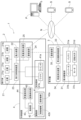
本実施形態に係る作業用飛行体1の装置構成について説明する。図1に示すように、作業用飛行体1は、飛行体2と、草刈機3と、飛行体2と草刈機3との間に接続された作業装置4とを備える。作業用飛行体1が飛行している状態において、作業装置4により草刈機3が飛行体2から離間する姿勢を取る。作業用飛行体1は、この姿勢において、草刈機3を傾斜地に接触させて、草刈機3に草刈作業を実施させることができる。なお、以下の説明において前後方向を言及するときは、特記しない限り、図1の矢印Fの方向を「前」といい、矢印Rの方向を「後」という。 (Basic configuration of work vehicle)
The device configuration of theworking aircraft 1 according to this embodiment will be described. As shown in FIG. 1, the working aircraft 1 comprises an aircraft 2, a grass cutter 3, and a work device 4 connected between the aircraft 2 and the grass cutter 3. When the working aircraft 1 is flying, the work device 4 causes the grass cutter 3 to assume a posture in which it is separated from the aircraft 2. In this posture, the working aircraft 1 can bring the grass cutter 3 into contact with a slope and cause the grass cutter 3 to perform grass cutting work. In the following description, when referring to the front-rear direction, the direction of the arrow F in FIG. 1 will be referred to as "front" and the direction of the arrow R will be referred to as "rear" unless otherwise specified.
本実施形態に係る作業用飛行体1の装置構成について説明する。図1に示すように、作業用飛行体1は、飛行体2と、草刈機3と、飛行体2と草刈機3との間に接続された作業装置4とを備える。作業用飛行体1が飛行している状態において、作業装置4により草刈機3が飛行体2から離間する姿勢を取る。作業用飛行体1は、この姿勢において、草刈機3を傾斜地に接触させて、草刈機3に草刈作業を実施させることができる。なお、以下の説明において前後方向を言及するときは、特記しない限り、図1の矢印Fの方向を「前」といい、矢印Rの方向を「後」という。 (Basic configuration of work vehicle)
The device configuration of the
図1~図2に示すように、飛行体2は、推進装置21(主翼21a及び副翼21b)、動力装置22、飛行体制御装置23、通信装置24、および衛星測位装置25を備えている。推進装置21は、複数(本実施形態では2つ)の主翼21a及び複数(本実施形態では4つ)の副翼21bとして実装されている。2つの主翼21aは、回転翼が前方に向けて配置される推進モードと、回転翼が上方に向けて配置されるホバリングモードとに亘って姿勢変更可能である。4つの副翼21bは、主に飛行体2の姿勢の制御に用いられる。推進モードでは、飛行体2を前方に向けて推進させやすく、ホバリングモードでは、飛行体2の水平位置を変更させずに停滞させやすい。なお、推進装置21(主翼21a及び副翼21b)は、尾翼を有していてもよい。
As shown in Figs. 1 and 2, the flying object 2 is equipped with a propulsion device 21 (main wing 21a and sub-wing 21b), a power unit 22, an flying object control device 23, a communication device 24, and a satellite positioning device 25. The propulsion device 21 is implemented as a plurality of main wings 21a (two in this embodiment) and a plurality of sub-wings 21b (four in this embodiment). The two main wings 21a can change their attitude between a propulsion mode in which the rotors are positioned facing forward and a hovering mode in which the rotors are positioned facing upward. The four sub-wings 21b are mainly used to control the attitude of the flying object 2. In the propulsion mode, it is easy to propel the flying object 2 forward, and in the hovering mode, it is easy to keep the flying object 2 stationary without changing its horizontal position. The propulsion device 21 (main wing 21a and sub-wing 21b) may have a tail.
動力装置22は、電気駆動のバッテリ、及び/又はガソリン等の燃料駆動のエンジンとして実装されている。本実施形態における動力装置22は、エンジンと発電機とバッテリとを備えている。発電機は、エンジンから出力される動力により発電し、発電した電力をバッテリに蓄電させる。推進装置21は、エンジンから出力される動力、発電機が発電した電力またはバッテリに蓄電された電力により作動する。例えば、主翼21aはエンジンから出力される動力で作動し、副翼21bは発電機が発電した電力またはバッテリに蓄電された電力により作動する。飛行体2は、動力装置22が発生させる駆動力によって推進装置21(主翼21a及び副翼21b)を運転し、推進装置21(主翼21a及び副翼21b)によって生み出される推進力によって飛行する。
The power unit 22 is implemented as an electrically powered battery and/or an engine powered by a fuel such as gasoline. In this embodiment, the power unit 22 includes an engine, a generator, and a battery. The generator generates electricity using power output from the engine and stores the generated electricity in the battery. The propulsion unit 21 operates using power output from the engine, electricity generated by the generator, or electricity stored in the battery. For example, the main wing 21a operates using power output from the engine, and the auxiliary wing 21b operates using electricity generated by the generator or electricity stored in the battery. The flying object 2 drives the propulsion unit 21 (main wing 21a and auxiliary wing 21b) using the driving force generated by the power unit 22, and flies using the propulsion force generated by the propulsion unit 21 (main wing 21a and auxiliary wing 21b).
飛行体制御装置23は、演算処理装置と記憶装置とを有するコンピュータとして実装されている。飛行体制御装置23は、飛行体2に設けられた様々な計器からの信号の入力を受付可能であるとともに、飛行体2の各部を制御するための信号を出力可能に構成されている。
The aircraft control device 23 is implemented as a computer having an arithmetic processing unit and a storage device. The aircraft control device 23 is configured to be able to receive input signals from various instruments provided on the aircraft 2, and to be able to output signals for controlling each part of the aircraft 2.
飛行体2に設けられる計器(不図示)としては、飛行体2全体の運転状態を示す計器(速度計、高度計など)、推進装置21(主翼21a及び副翼21b)の運転状態を示す計器(主翼21a及び副翼21bの回転計など)、動力装置22の運転状態を示す計器(バッテリ残量計など)が例示されるが、これらに限定されない。
Examples of instruments (not shown) provided on the flying object 2 include, but are not limited to, instruments that indicate the operating state of the flying object 2 as a whole (such as a speedometer and an altimeter), instruments that indicate the operating state of the propulsion system 21 (such as tachometers for the main wing 21a and the secondary wing 21b), and instruments that indicate the operating state of the power unit 22 (such as a battery level indicator).
通信装置24は、飛行体制御装置23と、飛行体2の外部に設けられた装置との間での通信を可能にするための通信インターフェースである。飛行体制御装置23は、通信装置24を介して、草刈機3の草刈機制御装置33と通信可能である。また、飛行体制御装置23は、携帯電話網Nを経由して、作業用飛行体1が作業を実施する傾斜地を管理する傾斜地管理システムを構成するコンピュータPやスマートフォンSなどとも通信可能である。
The communication device 24 is a communication interface that enables communication between the aircraft control device 23 and devices provided outside the aircraft 2. The aircraft control device 23 can communicate with the grass cutter control device 33 of the grass cutter 3 via the communication device 24. The aircraft control device 23 can also communicate with a computer P and a smartphone S that constitute a slope management system that manages the slope on which the work aircraft 1 performs work, via a mobile phone network N.
衛星測位装置25は、人工衛星からのGNSS(Global Navigation Satellite System)の信号を受信し、受信した信号に基づいて飛行体2の位置を示す測位データを取得し、飛行体制御装置23へ送信する。GNSSとしては、GPS、QZSS、Galileо、GLОNASS、BeiDouなどを利用可能である。
The satellite positioning device 25 receives GNSS (Global Navigation Satellite System) signals from artificial satellites, obtains positioning data indicating the position of the aircraft 2 based on the received signals, and transmits the data to the aircraft control device 23. Available GNSS include GPS, QZSS, Galileo, GLONASS, and BeiDou.
飛行体2の飛行状態における下面側には、草刈機3(対象物)を吊り下げる作業装置4が接続されている。「草刈機3を吊り下げる」とは、飛行体2が草刈機3の姿勢を変更可能な形態で草刈機3が飛行体2に対して重量方向下側に設けられている状態を意味する。作業装置4は、支持部材41、駆動部42、および制御部43を備えており、飛行体2と連結されていることから通信装置24および衛星測位装置25を飛行体2と兼用可能に備えている。また、作業装置4には、支持部材41の荷重を検知する荷重検知部44、および草刈機3の揺動を検知する揺動検知部45を備えている。本実施形態における作業装置4は、主翼21aにより飛行体2を推進(浮上,上昇,下降)させて飛行させるための揚力を発生させ、副翼21bを飛行体2の姿勢の制御に用いる。なお、作業装置4は、通信装置24および衛星測位装置25を飛行体2と兼用せずに個別に備えていてもよいし、後述する草刈機3の衛星測位装置34および通信装置35と兼用してもよい。また、制御部43は、飛行体制御装置23や後述する草刈機制御装置33に内蔵されていてもよいし、遠隔地にあるサーバに設けられていてもよい。
A working device 4 for suspending a grass cutter 3 (target object) is connected to the underside of the flying object 2 in flight. "Suspending the grass cutter 3" means that the flying object 2 is in a form in which the attitude of the grass cutter 3 can be changed and the grass cutter 3 is arranged on the lower side of the flying object 2 in the weight direction. The working device 4 includes a support member 41, a drive unit 42, and a control unit 43, and is connected to the flying object 2, so that the communication device 24 and the satellite positioning device 25 can be used in common with the flying object 2. The working device 4 also includes a load detection unit 44 for detecting the load on the support member 41, and a swing detection unit 45 for detecting the swing of the grass cutter 3. In this embodiment, the working device 4 generates lift for propelling (flying, ascending, descending) the flying object 2 with the main wing 21a to fly, and uses the sub-wing 21b to control the attitude of the flying object 2. The work device 4 may have a communication device 24 and a satellite positioning device 25 separately from the flying object 2, or may share the communication device 24 and the satellite positioning device 34 and the communication device 35 of the grass cutter 3, which will be described later. The control unit 43 may be built into the flying object control device 23 or the grass cutter control device 33, which will be described later, or may be provided in a server in a remote location.
作業装置4は、一端側が飛行体2に、他端側が草刈機3にそれぞれ接続されているユニットである。飛行体2と草刈機3とが作業装置4を介して接続されていることによって、作業用飛行体1が飛行している状態において、作業装置4に接続された草刈機3が飛行体2から離間する姿勢を取る。
The working device 4 is a unit connected at one end to the flying object 2 and at the other end to the grass cutter 3. Because the flying object 2 and the grass cutter 3 are connected via the working device 4, when the working flying object 1 is flying, the grass cutter 3 connected to the working device 4 takes a position away from the flying object 2.
支持部材41は、草刈機3を吊り下げ支持する複数(本実施形態では4本)のロープ状のワイヤ41bとワイヤ41bを伸縮させる複数(本実施形態では4つ)のウインチ41a(巻上機構の一例)とを有している。それぞれのウインチ41aは、それぞれのワイヤ41bに個別に設けられており、制御部43によりウインチ41aを回転させる調節機構42a(例えばモータ)の駆動力を制御して、ワイヤ41bの姿勢(長さ)を各別に調節する。つまり、調節機構42aがウインチ41aを動作させて、ロープ状のワイヤ41bの繰出し量を調整することで、ワイヤ41bを介して接続される飛行体2と草刈機3との相対位置を能動的に変更できる。なお、支持部材41は、油圧式、空気圧式、電動式の伸縮可能な金属部材で構成してもよく、この場合はウインチ41aを省略することができる。
The support member 41 has a plurality of (four in this embodiment) rope-like wires 41b that suspend and support the grass cutter 3, and a plurality of (four in this embodiment) winches 41a (an example of a winding mechanism) that expands and contracts the wires 41b. Each winch 41a is provided individually for each wire 41b, and the control unit 43 controls the driving force of an adjustment mechanism 42a (e.g., a motor) that rotates the winch 41a to adjust the attitude (length) of each wire 41b. In other words, the adjustment mechanism 42a operates the winch 41a to adjust the amount of payout of the rope-like wire 41b, thereby actively changing the relative position of the flying object 2 and the grass cutter 3 connected via the wire 41b. The support member 41 may be composed of a hydraulic, pneumatic, or electrically expandable metal member, in which case the winch 41a can be omitted.
それぞれのワイヤ41bの一端側は、ウインチ41aに接続されており、このウインチ41aが移動機構42bを介して飛行体2に接続されている。それぞれのワイヤ41bの他端側は、草刈機3の複数(本実施形態では4隅)の角部に係止された係止部41b1(例えばフック)により、草刈機3に接続されている。複数の支持部材41による支持荷重は、草刈機3の重量以上に設定されており、複数の支持部材41により草刈機3の全荷重を負担する。その結果、草刈機3が落下するといった不都合を防止し、ワイヤ41bを切断せずに傾斜地まで草刈機3を運搬することができる。また、それぞれの支持部材41による支持荷重は、草刈機3の重量以上に設定されており、仮に草刈機3の荷重が1つの支持部材41に一時的に集中しても耐えうる構造となっている。
One end of each wire 41b is connected to a winch 41a, which is connected to the flying object 2 via a moving mechanism 42b. The other end of each wire 41b is connected to the grass cutter 3 by engaging parts 41b1 (e.g., hooks) that are engaged with multiple corners (four corners in this embodiment) of the grass cutter 3. The load supported by the multiple support members 41 is set to be greater than or equal to the weight of the grass cutter 3, and the multiple support members 41 bear the entire load of the grass cutter 3. As a result, the grass cutter 3 is prevented from falling, and the grass cutter 3 can be transported to a slope without cutting the wire 41b. The load supported by each support member 41 is set to be greater than or equal to the weight of the grass cutter 3, and the structure is such that it can withstand even if the load of the grass cutter 3 is temporarily concentrated on one support member 41.
また、支持部材41は、ウインチ41aとワイヤ41bとの接続角度が調整可能に構成されている。さらに、ぞれぞれのウインチ41aは、移動機構42bにより水平方向に移動可能に構成されており、ウインチ41aおよびワイヤ41bを一組として複数の支持部材41が水平方向に移動する。つまり、移動機構42bにより複数の支持部材41におけるそれぞれの最大離間距離を広げたり狭めたりして姿勢を変更することができる。制御部43による調節機構42aや移動機構42bの姿勢制御としては、飛行体2がホバリング飛行している際に実行することが好ましい。また、飛行体2の通常飛行時に姿勢制御するだけでなく、飛行体2の急停止時に姿勢制御してもよい。
Furthermore, the support member 41 is configured so that the connection angle between the winch 41a and the wire 41b can be adjusted. Furthermore, each winch 41a is configured so that it can be moved horizontally by the movement mechanism 42b, and the multiple support members 41 move horizontally with the winch 41a and wire 41b as a set. In other words, the movement mechanism 42b can increase or decrease the maximum separation distance between the multiple support members 41 to change the attitude. It is preferable that the attitude control of the adjustment mechanism 42a and the movement mechanism 42b by the control unit 43 be performed when the aircraft 2 is in hovering flight. Furthermore, attitude control may be performed not only during normal flight of the aircraft 2, but also when the aircraft 2 suddenly stops.
駆動部42は、調節機構42aおよび移動機構42bを有している。調節機構42aは、ウインチ41aを回転駆動させるモータで構成されており、支持部材41の姿勢を変更させるようにワイヤ41bを伸縮させて草刈機3の揺動を打ち消す。また、調節機構42aは、ワイヤ41bが草刈機3に対して張力を発生させるようにウインチ41aを回転駆動させる。
The drive unit 42 has an adjustment mechanism 42a and a movement mechanism 42b. The adjustment mechanism 42a is composed of a motor that rotates the winch 41a, and cancels the rocking of the grass cutter 3 by expanding and contracting the wire 41b to change the posture of the support member 41. The adjustment mechanism 42a also rotates the winch 41a so that the wire 41b generates tension on the grass cutter 3.
移動機構42bは、飛行体2の下部に固定された矩形状の枠状部材で形成されている。この移動機構42bは、ウインチ41aの水平移動を案内するレール42b1と、レール42b1に沿ってウインチ41aを移動させるギア部42b2と、ギア部42b2のレール42b1の位置を変更させるモータ42b3とを有している。例えば、レール42b1上のギア部42b2としては、モータ42b3の回転力を直進力に変換させるラックアンドピニオン等が挙げられる。本実施形態における移動機構42bは、ギア部42b2により、それぞれの支持部材41の位置を各別に変更可能に構成している。なお、移動機構42bは、一対の支持部材41又は全ての支持部材41を同時に移動させるように構成してもよい。
The moving mechanism 42b is formed of a rectangular frame-shaped member fixed to the bottom of the flying object 2. The moving mechanism 42b has a rail 42b1 that guides the horizontal movement of the winch 41a, a gear unit 42b2 that moves the winch 41a along the rail 42b1, and a motor 42b3 that changes the position of the rail 42b1 of the gear unit 42b2. For example, the gear unit 42b2 on the rail 42b1 may be a rack and pinion that converts the rotational force of the motor 42b3 into a linear force. The moving mechanism 42b in this embodiment is configured so that the position of each support member 41 can be changed individually by the gear unit 42b2. The moving mechanism 42b may be configured to move a pair of support members 41 or all of the support members 41 simultaneously.
制御部43は、演算処理装置と記憶装置とを有するコンピュータとして実装されている。制御部43は、調節機構42aおよび移動機構42bの駆動を制御する。また、制御部43は、作業装置4に設けられた様々な計器(例えば荷重検知部44)からの信号の入力を受付可能であるとともに、作業装置4の各部を制御するための信号を出力可能に構成されている。
The control unit 43 is implemented as a computer having an arithmetic processing unit and a storage device. The control unit 43 controls the driving of the adjustment mechanism 42a and the movement mechanism 42b. The control unit 43 is also configured to be able to receive input signals from various instruments (e.g., the load detection unit 44) provided in the working device 4, and to be able to output signals for controlling each part of the working device 4.
荷重検知部44は、それぞれの支持部材41の他端側に設けられた係止部41b1に接続された公知のロードセル等で構成されている。揺動検知部45は、草刈機3の揺動を検知する公知のIMUセンサ等で構成されており、本実施形態では、草刈機3にIMUセンサを固定して、IMUセンサの信号を制御部43が受信する。揺動検知部45は、草刈機3の加速度、回転、位置変化といった物理運動パラメータを検知する。なお、揺動検知部45を支持部材41に設置して草刈機3の揺動を検知してもよいし、揺動検知部45により飛行体2の揺動自体を検知してもよい。
The load detection unit 44 is composed of a known load cell or the like connected to a locking portion 41b1 provided on the other end side of each support member 41. The sway detection unit 45 is composed of a known IMU sensor or the like that detects the sway of the grass cutter 3, and in this embodiment, the IMU sensor is fixed to the grass cutter 3, and the control unit 43 receives the signal from the IMU sensor. The sway detection unit 45 detects physical motion parameters such as the acceleration, rotation, and position change of the grass cutter 3. The sway detection unit 45 may be installed on the support member 41 to detect the sway of the grass cutter 3, or the sway detection unit 45 may detect the sway of the flying object 2 itself.
草刈機3は、草刈駆動部31、被接続部材32、草刈機制御装置33、衛星測位装置34、および通信装置35を備えている。
The lawnmower 3 includes a lawnmower drive unit 31, a connected member 32, a lawnmower control device 33, a satellite positioning device 34, and a communication device 35.
草刈駆動部31は、バッテリ31a、インバータ31b、モータ31c、および回転刈刃31dを有している。バッテリ31aからの直流電流をインバータ31bにより交流電流に変換してモータ31cを駆動させ、このモータ31cにより回転刈刃31dを回転させることにより、草刈りを実行する。
The grass cutting drive unit 31 has a battery 31a, an inverter 31b, a motor 31c, and a rotary cutting blade 31d. The direct current from the battery 31a is converted to alternating current by the inverter 31b to drive the motor 31c, and the motor 31c rotates the rotary cutting blade 31d to perform grass cutting.
被接続部材32は、作業装置4のワイヤ41bの他端が係止される被係止部となっている。被接続部材32は、ワイヤ41bの他端側の係止部41b1に係止されるU字ブロックやフック穴などで構成されている。被接続部材32と作業装置4のワイヤ41bとの接続構造は特に限定されず、例えば、ソケットとプラグのように雄雌係合であってもよい。本実施形態における被接続部材32は、草刈機3の上面角部に4つ設けられており、作業装置4のワイヤ41bが4つ設けられていることに対応している。4つの被接続部材32のそれぞれは、ワイヤ41bの他端が接続されたことを検知可能なセンサを設けていてもよい。
The connected member 32 is a locking portion to which the other end of the wire 41b of the working device 4 is locked. The connected member 32 is composed of a U-shaped block or a hook hole that is locked to the locking portion 41b1 on the other end side of the wire 41b. The connection structure between the connected member 32 and the wire 41b of the working device 4 is not particularly limited, and may be male-female engagement, for example, like a socket and a plug. In this embodiment, four connected members 32 are provided at the corners of the top surface of the grass cutter 3, corresponding to the four wires 41b of the working device 4. Each of the four connected members 32 may be provided with a sensor that can detect that the other end of the wire 41b is connected.
草刈機制御装置33は、演算処理装置と記憶装置とを有するコンピュータとして実装されている。草刈機制御装置33は、草刈機3に設けられた様々な計器からの信号の入力を受付可能であるとともに、草刈機3の各部を制御するための信号を出力可能に構成されている。
The grass cutter control device 33 is implemented as a computer having an arithmetic processing device and a storage device. The grass cutter control device 33 is configured to be able to receive input signals from various instruments provided on the grass cutter 3, and to be able to output signals for controlling each part of the grass cutter 3.
草刈機3に設けられうる計器としては、草刈機3全体の運転状態を示す計器(速度計など)、草刈駆動部31の運転状態を示す計器(刈刃回転計、バッテリ残量計など)が例示されるが、これらに限定されない。
Examples of instruments that may be provided on the lawnmower 3 include, but are not limited to, instruments that indicate the operating state of the lawnmower 3 as a whole (such as a speedometer) and instruments that indicate the operating state of the grass-cutting drive unit 31 (such as a blade tachometer and a battery level meter).
衛星測位装置34は、人工衛星からのGNSS(Global Navigation Satellite System)の信号を受信し、受信した信号に基づいて草刈機3の位置を示す測位データを取得し、草刈機制御装置33へ送信する。GNSSとしては、GPS、QZSS、Galileо、GLОNASS、BeiDouなどを利用可能である。
The satellite positioning device 34 receives GNSS (Global Navigation Satellite System) signals from artificial satellites, obtains positioning data indicating the position of the grass cutter 3 based on the received signals, and transmits the data to the grass cutter control device 33. GPS, QZSS, Galileo, GLONASS, BeiDou, etc. can be used as the GNSS.
通信装置35は、草刈機制御装置33と、草刈機3の外部に設けられた装置との間での通信を可能にするための通信インターフェースである。草刈機制御装置33は、通信装置35を介して、飛行体2の飛行体制御装置23と通信可能である。また、草刈機制御装置33は、携帯電話網Nを経由して、作業用飛行体1が作業を実施する傾斜地を管理する傾斜地管理システムを構成するコンピュータPやスマートフォンSなどとも通信可能である。
The communication device 35 is a communication interface that enables communication between the grass cutter control device 33 and devices provided outside the grass cutter 3. The grass cutter control device 33 can communicate with the aircraft control device 23 of the aircraft 2 via the communication device 35. The grass cutter control device 33 can also communicate with a computer P and a smartphone S that constitute a slope management system that manages the slopes on which the work aircraft 1 performs work, via a mobile phone network N.
(作業用飛行体の変形例)
図3に示すように、作業用飛行体1は、上述した実施形態における移動機構42bを省略してもよい。この場合、ウインチ41aが飛行体2に取り付けられていてもよい。移動機構42bを省略した場合でも、調節機構42aで支持部材41を伸縮させることにより、草刈機3の揺動を打ち消すことができる。 (Modification of the Work Aircraft)
3, the movingmechanism 42b in the above-described embodiment may be omitted from the working aircraft 1. In this case, the winch 41a may be attached to the aircraft 2. Even if the moving mechanism 42b is omitted, the rocking motion of the grass cutter 3 can be counteracted by extending and contracting the support member 41 with the adjustment mechanism 42a.
図3に示すように、作業用飛行体1は、上述した実施形態における移動機構42bを省略してもよい。この場合、ウインチ41aが飛行体2に取り付けられていてもよい。移動機構42bを省略した場合でも、調節機構42aで支持部材41を伸縮させることにより、草刈機3の揺動を打ち消すことができる。 (Modification of the Work Aircraft)
3, the moving
(作業装置の制御形態)
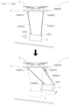
以下、図4~図5を用いて、作業装置4の制御形態について説明する。本実施形態における制御部43は、草刈機3の揺動を打ち消すように調節機構42aを制御して支持部材41(ワイヤ41b)を伸縮させる。例えば、図4に示すように、作業用飛行体1の前から後に向かって強風等の外力が草刈機3に作用した場合、下図の2点鎖線に示すように草刈機3の後方側が垂れ下がるように揺動する。そこで、制御部43は、後側にあるワイヤ41bの長さを縮小するように調節機構42aを制御して、ウインチ41aを巻き上げる。その結果、図4の下図実線で示すように、草刈機3を傾斜地に沿った水平姿勢にし、草刈機3に掛かる外力を打ち消す。このように、制御部43は、支持部材41(ワイヤ41b)が草刈機3に対して張力を発生させるように調節機構42aを制御する。つまり、作業装置4のワイヤ41bには草刈機3に対して張力が常に作用するため、支持部材41により草刈機3の姿勢を適正なものにできる。特に、強風などにより草刈機3が左右に揺動し、揺れた方向の支持部材41が撓んだ場合でも、撓んだ支持部材41を縮めて張力を発生させることにより、支持部材41に掛かる荷重を均一にすることが可能となる。 (Control form of working device)
The control form of the workingdevice 4 will be described below with reference to Figs. 4 and 5. The control unit 43 in this embodiment controls the adjustment mechanism 42a to extend and retract the support member 41 (wire 41b) so as to cancel the swinging of the grass cutter 3. For example, as shown in Fig. 4, when an external force such as a strong wind acts on the grass cutter 3 from the front to the rear of the working aircraft 1, the rear side of the grass cutter 3 swings so as to sag as shown by the two-dot chain line in the lower figure. Therefore, the control unit 43 controls the adjustment mechanism 42a to reduce the length of the wire 41b on the rear side, and winds up the winch 41a. As a result, as shown by the solid line in the lower figure of Fig. 4, the grass cutter 3 is placed in a horizontal position along the slope, canceling out the external force acting on the grass cutter 3. In this way, the control unit 43 controls the adjustment mechanism 42a so that the support member 41 (wire 41b) generates tension on the grass cutter 3. In other words, tension is always applied to the wire 41b of the working device 4 relative to the mower 3, so the posture of the mower 3 can be adjusted by the support member 41. In particular, even if the mower 3 swings left and right due to strong winds or the like and the support member 41 in the swinging direction is bent, the bent support member 41 can be contracted to generate tension, thereby making it possible to uniformly distribute the load on the support member 41.
以下、図4~図5を用いて、作業装置4の制御形態について説明する。本実施形態における制御部43は、草刈機3の揺動を打ち消すように調節機構42aを制御して支持部材41(ワイヤ41b)を伸縮させる。例えば、図4に示すように、作業用飛行体1の前から後に向かって強風等の外力が草刈機3に作用した場合、下図の2点鎖線に示すように草刈機3の後方側が垂れ下がるように揺動する。そこで、制御部43は、後側にあるワイヤ41bの長さを縮小するように調節機構42aを制御して、ウインチ41aを巻き上げる。その結果、図4の下図実線で示すように、草刈機3を傾斜地に沿った水平姿勢にし、草刈機3に掛かる外力を打ち消す。このように、制御部43は、支持部材41(ワイヤ41b)が草刈機3に対して張力を発生させるように調節機構42aを制御する。つまり、作業装置4のワイヤ41bには草刈機3に対して張力が常に作用するため、支持部材41により草刈機3の姿勢を適正なものにできる。特に、強風などにより草刈機3が左右に揺動し、揺れた方向の支持部材41が撓んだ場合でも、撓んだ支持部材41を縮めて張力を発生させることにより、支持部材41に掛かる荷重を均一にすることが可能となる。 (Control form of working device)
The control form of the working
また、制御部43は、揺動検知部45で検知した草刈機3の揺動加速度の変化方向側にある支持部材41を伸縮させるように調節機構42aを制御する。特に、揺動加速度の変化方向にある支持部材41は、草刈機3に掛かる慣性力を効果的に低減させることが可能であるため、草刈機3の揺動を速やかに抑制することができる。図4に示すように、草刈機3が強風に煽られたとき揺動加速度の変化方向にある支持部材41(図4に示す後側の支持部材41)を伸縮させれば、確実に揺動を抑制することができる。このとき、制御部43は、飛行体2の衛星測位装置25と草刈機3の衛星測位装置34とを位置検知部として、この位置検知部から信号を受信することにより、支持部材41と草刈機3との相対位置を検知することが好ましい。このように、支持部材41と草刈機3との相対位置を検知すれば、水平方向の揺れを検知することが可能となり、複数の支持部材41による支持中心が草刈機3の重心位置となるように調節機構42aを制御することにより調節機構42aの制御性能が向上する。
In addition, the control unit 43 controls the adjustment mechanism 42a to expand and contract the support member 41 located in the direction of change in the oscillation acceleration of the grass cutter 3 detected by the oscillation detection unit 45. In particular, the support member 41 located in the direction of change in the oscillation acceleration can effectively reduce the inertial force acting on the grass cutter 3, so that the oscillation of the grass cutter 3 can be quickly suppressed. As shown in FIG. 4, when the grass cutter 3 is blown by a strong wind, the oscillation can be reliably suppressed by expanding and contracting the support member 41 located in the direction of change in the oscillation acceleration (the rear support member 41 shown in FIG. 4). At this time, it is preferable that the control unit 43 detects the relative positions of the support member 41 and the grass cutter 3 by receiving signals from the position detection units, using the satellite positioning device 25 of the flying object 2 and the satellite positioning device 34 of the grass cutter 3 as position detection units. In this way, by detecting the relative positions of the support members 41 and the grass cutter 3, it is possible to detect horizontal shaking, and by controlling the adjustment mechanism 42a so that the support center of the multiple support members 41 is aligned with the center of gravity of the grass cutter 3, the control performance of the adjustment mechanism 42a is improved.
また、飛行体2が例えばホバリング飛行から前進する際には、飛行体2の移動に起因して草刈機3に揺動加速度が生じる。そこで、制御部43は、飛行体2の運転状態を示す計器から得られた飛行体2の移動速度情報を加味して、草刈機3の揺動加速度の変化方向側にある支持部材41を伸縮させるように調節機構42aを制御してもよい。これにより、飛行体2の移動に起因する草刈機3の揺動を確実に打ち消すことができる。
Furthermore, when the flying object 2 moves forward from hovering flight, for example, a rocking acceleration occurs in the grass cutter 3 due to the movement of the flying object 2. Therefore, the control unit 43 may take into account the movement speed information of the flying object 2 obtained from an instrument that indicates the operating state of the flying object 2 and control the adjustment mechanism 42a to expand and contract the support member 41 on the side of the direction of change in the rocking acceleration of the grass cutter 3. This makes it possible to reliably cancel out the rocking of the grass cutter 3 caused by the movement of the flying object 2.
制御部43は、姿勢検知部として荷重検知部44(ロードセル)を機能させる場合、支持部材41に掛かる負荷として荷重検知部44の検知情報を加味して、草刈機3の傾きを推定し、草刈機3の姿勢が水平となるように調節機構42aを制御してもよい。また、姿勢検知部として揺動検知部45(IMUセンサ)を機能させる場合、草刈機3自体の傾きとして揺動検知部45の検知情報を加味して、草刈機3の姿勢が水平となるように調節機構42aを制御してもよい。なお、草刈機3の姿勢が水平となるように調節機構42aを制御することに代えて、草刈機3自体に姿勢自動修正機能を持たせてもよい。この場合、草刈機3自体に搭載されたIMUセンサにより草刈機3の傾きを検知し、草刈機3のアクチュエータの軸芯位置を補正したり、重量バランスを調整する移動部材を設けたりすればよい。
When the load detection unit 44 (load cell) functions as the posture detection unit, the control unit 43 may estimate the inclination of the grass cutter 3 by taking into account the detection information of the load detection unit 44 as the load applied to the support member 41, and control the adjustment mechanism 42a so that the posture of the grass cutter 3 is horizontal. When the swing detection unit 45 (IMU sensor) functions as the posture detection unit, the control unit 43 may control the adjustment mechanism 42a so that the posture of the grass cutter 3 is horizontal by taking into account the detection information of the swing detection unit 45 as the inclination of the grass cutter 3 itself. Note that instead of controlling the adjustment mechanism 42a so that the posture of the grass cutter 3 is horizontal, the grass cutter 3 itself may have an automatic posture correction function. In this case, the inclination of the grass cutter 3 may be detected by an IMU sensor mounted on the grass cutter 3 itself, and a moving member may be provided to correct the axis position of the actuator of the grass cutter 3 or adjust the weight balance.
さらに制御部43は、草刈機3の重量が小さいほど支持部材41の伸縮速度を大きくする及び/又は応答性を良くするように調節機構42aを制御することが好ましい。調節機構42aにより支持部材41を伸縮させて草刈機3の揺動を打ち消すため、作業用飛行体1に作業装置4を装着した場合、安定的な草刈作業を実施できる。特に、草刈機3の重量が小さいほど支持部材41の伸縮速度を大きく及び/又は応答性を良くすれば、重量が小さい場合は速やかに揺動を打ち消し、重量が大きい場合は支持部材41の伸縮速度を小さくする及び/又は応答性を鈍くすることにより、急激な慣性力が草刈機3に掛かり作業装置4が制御不能となる事態を回避できる。このように、支持部材41(ワイヤ41b)を伸縮させるだけで安定的な作業が可能となるため、草刈機3を目的地まで運搬できず、作業が開始できないといった不都合を簡便に解消できる。
Furthermore, it is preferable that the control unit 43 controls the adjustment mechanism 42a so that the extension speed of the support member 41 is increased and/or the responsiveness is improved as the weight of the grass cutter 3 decreases. Since the adjustment mechanism 42a extends and retracts the support member 41 to cancel the rocking of the grass cutter 3, stable grass cutting work can be performed when the working device 4 is attached to the working aircraft 1. In particular, if the extension speed of the support member 41 is increased and/or the responsiveness is improved as the weight of the grass cutter 3 decreases, the rocking can be quickly canceled when the weight is small, and the extension speed of the support member 41 is decreased and/or the responsiveness is slowed when the weight is large, thereby avoiding a situation in which a sudden inertial force is applied to the grass cutter 3 and the working device 4 becomes uncontrollable. In this way, stable work is possible simply by extending and retracting the support member 41 (wire 41b), and thus the inconvenience of not being able to transport the grass cutter 3 to the destination and not being able to start work can be easily eliminated.
制御部43は、荷重検知部44で検出されたそれぞれの支持部材41による支持荷重が均一となるように調節機構42aを制御して支持部材41を伸縮させることが好ましい。複数の支持部材41における支持荷重の均一化を図れば、支持部材41の支持力を過剰に大きく設定する必要が無く、支持部材41の軽量化を図ることができる。また、支持荷重の均一化を図るために、支持部材41を伸縮させるだけであるため、制御が簡便である。
The control unit 43 preferably controls the adjustment mechanism 42a to extend or contract the support members 41 so that the support loads of each support member 41 detected by the load detection unit 44 are uniform. By equalizing the support loads of the multiple support members 41, it is not necessary to set the support force of the support members 41 excessively large, and the support members 41 can be made lighter. Furthermore, since the support members 41 only need to be extended or contracted to equalize the support loads, control is simple.
上述したように、本実施形態における作業装置4は、ウインチ41aとワイヤ41bとの接続角度が調整可能に構成されている。そこで、制御部43は、揺動検知部45で検知した草刈機3の揺動量が所定値以上であるとき、移動機構42bを制御して複数の支持部材41の最大離間距離を広げる。図5の2点鎖線に示すように、例えば、上下方向を揺動軸芯として草刈機3が回転した場合、揺動量が所定値以上となれば複数の支持部材41の最大離間距離を広げる。例えば図5の実線で示すように、4つの支持部材41を広げることにより、草刈機3の揺動に伴う慣性力を低減することが可能となる。また、図4~図5に示す揺動が同時に起こった場合、制御部43は、移動機構42bを制御して複数の支持部材41の水平位置を個別に調節して、複数の支持部材41による支持中心が草刈機3の重心位置となるように調節機構42aを制御することが好ましい。複数の支持部材41の支持中心が草刈機3の重心位置となるように制御すれば、草刈機3の揺動によりバランスが崩れるといった不都合を防止できる。このように、草刈機3の揺動量に応じてウインチ41aとワイヤ41bとの接続角度を変更することにより、草刈機3の揺動に伴う慣性力を低減することが可能となる。その結果、草刈機3の揺動により伝達される作業装置4の振動を抑制することができる。
As described above, the working device 4 in this embodiment is configured so that the connection angle between the winch 41a and the wire 41b can be adjusted. Therefore, when the amount of swing of the grass cutter 3 detected by the swing detection unit 45 is equal to or greater than a predetermined value, the control unit 43 controls the moving mechanism 42b to widen the maximum separation distance of the multiple support members 41. As shown by the two-dot chain line in FIG. 5, for example, when the grass cutter 3 rotates with the vertical direction as the swing axis, if the amount of swing is equal to or greater than a predetermined value, the maximum separation distance of the multiple support members 41 is widened. For example, as shown by the solid line in FIG. 5, by widening the four support members 41, it is possible to reduce the inertial force associated with the swing of the grass cutter 3. In addition, when the swings shown in FIG. 4 to FIG. 5 occur simultaneously, it is preferable that the control unit 43 controls the moving mechanism 42b to individually adjust the horizontal positions of the multiple support members 41, and controls the adjustment mechanism 42a so that the support center of the multiple support members 41 is the center of gravity of the grass cutter 3. By controlling the support center of the multiple support members 41 to coincide with the center of gravity of the grass cutter 3, it is possible to prevent problems such as loss of balance due to the swinging of the grass cutter 3. In this way, by changing the connection angle between the winch 41a and the wire 41b according to the amount of swinging of the grass cutter 3, it is possible to reduce the inertial force associated with the swinging of the grass cutter 3. As a result, it is possible to suppress the vibration of the working device 4 transmitted by the swinging of the grass cutter 3.
[その他の実施形態]
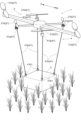
(1)上述した実施形態では、作業装置4を1つの飛行体2に接続する例を示したが、図6に示すように、それぞれの支持部材41に対応して複数の飛行体2を各別に接続してもよい。この場合、それぞれの飛行体2の相対位置を変更させることにより、上述した移動機構42bの機能を発揮することができる。また、図7に示すように、複数の主翼のみで構成される推進装置21であってもよく、この場合、複数の主翼が姿勢変更機能も兼ね備えることとなる。上述した実施形態における主翼21a及び副翼21bの数量は限定されず、例えば、副翼21bを8つ設けてもよい。 [Other embodiments]
(1) In the above-described embodiment, an example in which the workingdevice 4 is connected to one flying object 2 has been shown, but as shown in FIG. 6, multiple flying objects 2 may be connected separately corresponding to each support member 41. In this case, the function of the above-described movement mechanism 42b can be exerted by changing the relative positions of each flying object 2. In addition, as shown in FIG. 7, the propulsion device 21 may be composed of only multiple main wings, in which case the multiple main wings also have an attitude changing function. The number of main wings 21a and sub-wings 21b in the above-described embodiment is not limited, and for example, eight sub-wings 21b may be provided.
(1)上述した実施形態では、作業装置4を1つの飛行体2に接続する例を示したが、図6に示すように、それぞれの支持部材41に対応して複数の飛行体2を各別に接続してもよい。この場合、それぞれの飛行体2の相対位置を変更させることにより、上述した移動機構42bの機能を発揮することができる。また、図7に示すように、複数の主翼のみで構成される推進装置21であってもよく、この場合、複数の主翼が姿勢変更機能も兼ね備えることとなる。上述した実施形態における主翼21a及び副翼21bの数量は限定されず、例えば、副翼21bを8つ設けてもよい。 [Other embodiments]
(1) In the above-described embodiment, an example in which the working
(2)作業装置4を構成する各要素が、様々な形態の作業用飛行体1の間で流用可能なように設計されてもよい。例えば、作業装置4と飛行体2との接続構造が、様々な種類の飛行体2における共通規格として設計されていてもよい。また、例えば、作業装置4と草刈機3との接続構造が、様々な種類の草刈機3における共通規格として設計されていてもよい。
(2) Each element constituting the work device 4 may be designed to be compatible with various types of working aircraft 1. For example, the connection structure between the work device 4 and the aircraft 2 may be designed as a common standard for various types of aircraft 2. Also, for example, the connection structure between the work device 4 and the grass cutter 3 may be designed as a common standard for various types of grass cutters 3.
(3)飛行体2の主翼21aは、主翼21aの回転軸を機体左右方向に延びる軸芯周りに回転可能なように構成されていてもよい。すなわち、主翼21aは所謂ティルト式であってもよく、垂直着陸、ホバリング飛行、および高速水平飛行が可能となる。
(3) The main wing 21a of the aircraft 2 may be configured so that the axis of rotation of the main wing 21a can rotate around an axis extending in the left-right direction of the aircraft. In other words, the main wing 21a may be of a so-called tilt type, enabling vertical landing, hovering flight, and high-speed horizontal flight.
(4)作業装置4における作業の結果を取得する作業結果取得部を備えていてもよい。これにより、後工程の作業計画や次年度以降の作業計画を作成することが可能となる。この作業計画を管理サーバに記憶させておけば、様々な傾斜地における草刈作業に活用することができる。
(4) A work result acquisition unit that acquires the results of work performed by the work device 4 may be provided. This makes it possible to create work plans for subsequent processes and work plans for the next year and beyond. If this work plan is stored in the management server, it can be used for mowing work on various slopes.
(5)上述した実施形態では、草刈機3の4隅に支持部材41を設けて4点吊りとしたが、草刈機3の2隅と対辺の中央との3点吊りであってもよいし、2点吊り以上あれば特に限定されない。
(5) In the above embodiment, support members 41 are provided at the four corners of the mower 3 to provide four-point suspension, but it may also be three-point suspension, at two corners and the center of the opposite side of the mower 3, or there is no particular limitation as long as it is two or more points of suspension.
(6)支持部材41のウインチ41aは飛行体2側に設けたが、ウインチ41aを草刈機3側に設けて、飛行体2側を経由した支持部材40bやワイヤ41bにより草刈機3を吊り下げてもよい。
(6) The winch 41a of the support member 41 is provided on the aircraft 2 side, but the winch 41a may be provided on the grass cutter 3 side, and the grass cutter 3 may be suspended by the support member 40b and wire 41b that pass through the aircraft 2 side.
(7)上述した実施形態では、対象物として草刈機3を例示したが、荷物、薬剤散布装置、除雪装置、苗植付装置、コンバイン、警報装置、耕転装置等であってもよく、作業装置4に接続される対象物は特に限定されない。
(7) In the above-described embodiment, a grass cutter 3 is given as an example of the target object, but the target object may be luggage, a pesticide spraying device, a snow removal device, a seedling planting device, a combine harvester, an alarm device, a tilling device, etc., and there is no particular limit to the target object that may be connected to the work device 4.
(8)上述した実施形態では、作業装置4を作業用飛行体1に用いたが、クレーン等を用いる建設作業や土木作業等に用いてもよい。
(8) In the above-described embodiment, the work device 4 is used in the work aircraft 1, but it may also be used for construction work, civil engineering work, etc., that uses a crane, etc.
なお、上記の実施形態(別実施形態を含む、以下同じ)で開示される構成は、矛盾が生じない限り、他の実施形態で開示される構成と組み合わせて適用することが可能である。また、本明細書において開示された実施形態は例示であって、本発明の実施形態はこれに限定されず、本発明の目的を逸脱しない範囲内で適宜改変することが可能である。
The configurations disclosed in the above embodiments (including other embodiments, the same applies below) can be applied in combination with configurations disclosed in other embodiments, so long as no contradiction arises. Furthermore, the embodiments disclosed in this specification are merely examples, and the embodiments of the present invention are not limited thereto, and can be modified as appropriate within the scope of the purpose of the present invention.
本発明は、飛行体等に接続可能な作業装置に利用可能である。
The present invention can be used for work devices that can be connected to aircraft, etc.
3 :草刈機(対象物)
4 :作業装置
41 :支持部材
41a :ウインチ(巻上機構)
41b :ワイヤ
42a :調節機構
42b :移動機構
43 :制御部
44 :荷重検知部
45 :揺動検知部
3: Grass trimmer (object)
4: Working device 41:Support member 41a: Winch (hoisting mechanism)
41b:Wire 42a: Adjustment mechanism 42b: Movement mechanism 43: Control unit 44: Load detection unit 45: Swing detection unit
4 :作業装置
41 :支持部材
41a :ウインチ(巻上機構)
41b :ワイヤ
42a :調節機構
42b :移動機構
43 :制御部
44 :荷重検知部
45 :揺動検知部
3: Grass trimmer (object)
4: Working device 41:
41b:
Claims (7)
- 対象物を吊り下げる作業装置であって、
前記対象物を吊り下げ支持する複数の支持部材と、
複数の前記支持部材の姿勢を調節する調節機構と、
少なくとも前記調節機構の作動を制御する制御部と、を備え、
それぞれの前記支持部材は、前記対象物の角部に接続されている作業装置。 A work device for suspending an object,
A plurality of support members for suspending and supporting the object;
an adjustment mechanism for adjusting the attitudes of the plurality of support members;
A control unit that controls the operation of at least the adjustment mechanism,
A working device in which each of the support members is connected to a corner of the object. - 複数の前記支持部材による支持荷重は、前記対象物の重量以上である請求項1に記載の作業装置。 The work device according to claim 1, wherein the load supported by the multiple support members is equal to or greater than the weight of the object.
- 前記制御部は、複数の前記支持部材による支持中心が前記対象物の重心位置となるように前記調節機構を制御する請求項1又は2に記載の作業装置。 The working device according to claim 1 or 2, wherein the control unit controls the adjustment mechanism so that the support center of the multiple support members coincides with the center of gravity of the object.
- 前記支持部材は、ワイヤと当該ワイヤを伸縮させる巻上機構とを有しており、
前記巻上機構と前記ワイヤとの接続角度が調整可能に構成されている請求項1から3のいずれか一項に記載の作業装置。 The support member has a wire and a winding mechanism for extending and retracting the wire,
The working device according to claim 1 , wherein a connection angle between the winding mechanism and the wire is adjustable. - それぞれの前記支持部材は、支持荷重を検知する荷重検知部を有しており、
前記制御部は、前記荷重検知部で検出されたそれぞれの前記支持部材による支持荷重が均一となるように前記調節機構を制御して前記支持部材を伸縮させる請求項1から4のいずれか一項に記載の作業装置。 Each of the support members has a load detection portion that detects a support load,
The working device according to claim 1 , wherein the control unit controls the adjustment mechanisms to extend and contract the support members so that the support loads of the support members detected by the load detection units are uniform. - 前記対象物の揺動を検知する揺動検知部を更に備えた請求項1から5のいずれか一項に記載の作業装置。 The working device according to any one of claims 1 to 5, further comprising a vibration detection unit that detects the vibration of the object.
- 前記調節機構は、複数の前記支持部材を水平方向に移動させる移動機構を有しており、
前記制御部は、前記揺動検知部で検知した前記対象物の揺動量が所定値以上であるとき、前記移動機構を制御して複数の前記支持部材の最大離間距離を広げる請求項6に記載の作業装置。
the adjustment mechanism has a movement mechanism that moves the plurality of support members in a horizontal direction,
The working device according to claim 6 , wherein the control unit controls the movement mechanism to increase a maximum separation distance between the plurality of support members when an amount of swing of the object detected by the swing detection unit is equal to or greater than a predetermined value.
Priority Applications (1)
| Application Number | Priority Date | Filing Date | Title |
|---|---|---|---|
| PCT/JP2022/048351 WO2024142307A1 (en) | 2022-12-27 | 2022-12-27 | Work device |
Applications Claiming Priority (1)
| Application Number | Priority Date | Filing Date | Title |
|---|---|---|---|
| PCT/JP2022/048351 WO2024142307A1 (en) | 2022-12-27 | 2022-12-27 | Work device |
Publications (1)
| Publication Number | Publication Date |
|---|---|
| WO2024142307A1 true WO2024142307A1 (en) | 2024-07-04 |
Family
ID=91716807
Family Applications (1)
| Application Number | Title | Priority Date | Filing Date |
|---|---|---|---|
| PCT/JP2022/048351 WO2024142307A1 (en) | 2022-12-27 | 2022-12-27 | Work device |
Country Status (1)
| Country | Link |
|---|---|
| WO (1) | WO2024142307A1 (en) |
Citations (6)
| Publication number | Priority date | Publication date | Assignee | Title |
|---|---|---|---|---|
| KR101650525B1 (en) * | 2016-02-18 | 2016-08-24 | 아이씨티웨이주식회사 | Updated image data system by GIS based new data |
| US20160332851A1 (en) * | 2014-05-19 | 2016-11-17 | Google Inc. | Method of Actively Controlling Winch Swing via Modulated Uptake and Release |
| JP2017104365A (en) * | 2015-12-11 | 2017-06-15 | 株式会社ディスコ | Manned drone |
| CN107054653A (en) * | 2017-05-05 | 2017-08-18 | 西安工业大学 | Flight loading robot and method based on wire saws |
| US20180044019A1 (en) * | 2015-02-27 | 2018-02-15 | Geotech Ltd. | Electromagnetic survey system having tow assembly with attitude adjustment |
| CN210149563U (en) * | 2019-06-20 | 2020-03-17 | 郑州鑫雅图安科技有限公司 | Aviation rescue mounting device |
-
2022
- 2022-12-27 WO PCT/JP2022/048351 patent/WO2024142307A1/en unknown
Patent Citations (6)
| Publication number | Priority date | Publication date | Assignee | Title |
|---|---|---|---|---|
| US20160332851A1 (en) * | 2014-05-19 | 2016-11-17 | Google Inc. | Method of Actively Controlling Winch Swing via Modulated Uptake and Release |
| US20180044019A1 (en) * | 2015-02-27 | 2018-02-15 | Geotech Ltd. | Electromagnetic survey system having tow assembly with attitude adjustment |
| JP2017104365A (en) * | 2015-12-11 | 2017-06-15 | 株式会社ディスコ | Manned drone |
| KR101650525B1 (en) * | 2016-02-18 | 2016-08-24 | 아이씨티웨이주식회사 | Updated image data system by GIS based new data |
| CN107054653A (en) * | 2017-05-05 | 2017-08-18 | 西安工业大学 | Flight loading robot and method based on wire saws |
| CN210149563U (en) * | 2019-06-20 | 2020-03-17 | 郑州鑫雅图安科技有限公司 | Aviation rescue mounting device |
Similar Documents
| Publication | Publication Date | Title |
|---|---|---|
| JP6883296B2 (en) | Aircraft and control method of air vehicle | |
| JP6086519B1 (en) | Delivery rotorcraft | |
| JP2013079034A (en) | Rotorcraft for aerial photographing | |
| US11820506B2 (en) | Aerial vehicle with counterweight mechanism | |
| JP6630893B1 (en) | Hanging work support system | |
| JP6664820B1 (en) | Flying object | |
| US11628951B2 (en) | Electronic component and aircraft with electronic component attached thereto | |
| CN114793429A (en) | Lifting system | |
| WO2024142307A1 (en) | Work device | |
| WO2024142318A1 (en) | Work device and work flight vehicle | |
| WO2024142319A1 (en) | Work device | |
| JP6376580B1 (en) | Drone cart and drone cart unit | |
| JP6671705B2 (en) | Flying object | |
| JP6664821B2 (en) | Flying object | |
| WO2023203669A1 (en) | Work-performing aerial vehicle | |
| JP2020029257A (en) | Rotorcraft |
Legal Events
| Date | Code | Title | Description |
|---|---|---|---|
| 121 | Ep: the epo has been informed by wipo that ep was designated in this application |
Ref document number: 22970096 Country of ref document: EP Kind code of ref document: A1 |