WO2024142265A1 - コアレスモータ - Google Patents
コアレスモータ Download PDFInfo
- Publication number
- WO2024142265A1 WO2024142265A1 PCT/JP2022/048227 JP2022048227W WO2024142265A1 WO 2024142265 A1 WO2024142265 A1 WO 2024142265A1 JP 2022048227 W JP2022048227 W JP 2022048227W WO 2024142265 A1 WO2024142265 A1 WO 2024142265A1
- Authority
- WO
- WIPO (PCT)
- Prior art keywords
- coil
- conductor
- magnet
- coreless motor
- rotating shaft
- Prior art date
- Legal status (The legal status is an assumption and is not a legal conclusion. Google has not performed a legal analysis and makes no representation as to the accuracy of the status listed.)
- Ceased
Links
Images


Classifications
-
- H—ELECTRICITY
- H02—GENERATION; CONVERSION OR DISTRIBUTION OF ELECTRIC POWER
- H02K—DYNAMO-ELECTRIC MACHINES
- H02K23/00—DC commutator motors or generators having mechanical commutator; Universal AC/DC commutator motors
- H02K23/58—Motors or generators without iron cores
-
- H—ELECTRICITY
- H02—GENERATION; CONVERSION OR DISTRIBUTION OF ELECTRIC POWER
- H02K—DYNAMO-ELECTRIC MACHINES
- H02K3/00—Details of windings
- H02K3/04—Windings characterised by the conductor shape, form or construction, e.g. with bar conductors
Definitions
- Coreless motors do not have an iron core in which the coil serves as the core, and the rotor is formed only from windings.
- One way of winding the conductor that forms the coil is to form a hexagonal (tortoiseshell) shape.
- the conductor is wound circumferentially around the outer surface of a hexagonal prism, while being shifted slightly in the axial direction of the hexagonal prism to form a hexagonal spiral coil element, and the hexagonal prism is pulled out axially from the coil element to obtain a coil element formed in the spiral shape of a hexagonal prism using only the conductor.
- the space factor of the conductor in a cross section perpendicular to the axis of the cylinder tends to be smaller in the center of the coil (corresponding to the parallel part in a coil wound in a tortoise shell shape) than at the ends of the coil (corresponding to the hypotenuse part in a coil wound in a tortoise shell shape). Note that this is not limited to coils wound in a tortoise shell shape, but can also occur in coils wound in other shapes.
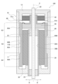
- the case 11 is formed in a cylindrical shape with one end closed.
- the case 11 is formed of a soft magnetic material such as metal.
- the case 11 may be formed of multiple parts.
- the brush base 12 is formed in a generally circular plate shape so as to close the open end of the case 11.
- the brush base 12 is formed of resin, for example.
- the brush base 12 is provided with a conductor connection member (not shown) that is connected to an external power source, and a brush 40 that is electrically connected to this connection member.
- a rotating shaft 20 is disposed at center C, which is the axis of the cylinder of the housing 10, penetrating the housing 10 and being rotatable around center C.
- a commutator 50 is fixed to the rotating shaft 20.
- a coil 60 is fixed to the commutator 50. In other words, the rotating shaft 20, coil 60, and commutator 50 make up a rotor.
- the commutator 50 has a conductive member that is electrically connected to the terminals 61a, 61b (see Figures 2, 3A, and 3B) of each of the conductors 61 of the multiple coil elements that make up the coil 60, and this conductive member extends to the outer circumferential surface of the boss and contacts the brush 40 provided on the brush stand 12.
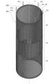
- the coil 60 is basically made up of conductors 61 joined together with adhesive, and does not have a core such as an iron core. For this reason, the coil 60 is lighter than a coil with a core.
- the coil 60 shown in FIG. 3B is used as one coil element, and multiple such coil elements are connected in the axial direction of the hexagonal prism described above, and the ends in the axial direction are connected around the center C shown in FIG. 3B so that one face 60A of the planar coil element faces outward (outer circumferential face) and the other face 60B faces inward (inner circumferential face), forming the cylindrical coil 60 shown in FIG. 2.
- the method of forming the coil 60 is not limited to the method described above.
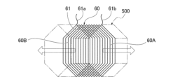
- the coil 60 thus formed is a tortoiseshell-shaped (hexagonal) coil 60, and as shown in FIG. 2, on both the outer peripheral surface 60A and the inner peripheral surface 60B, the conductor 61 (e.g., copper wire) has a parallel portion 62 extending parallel to the axis (center C) of the rotating shaft 20, a hypotenuse portion 63 connected to one end of the parallel portion 62, and a hypotenuse portion 64 connected to the other end of the parallel portion 62.
- the conductor 61 e.g., copper wire
- the conductor 61 of the oblique sides 63 and 64 extends in a direction inclined at a predetermined angle ⁇ with respect to a plane perpendicular to the direction of the center C (shown by a dashed line in FIG. 3B). As shown in FIG. 3B, the inclination angle ⁇ of the oblique side 63 and the inclination angle ⁇ of the oblique side 64 are in different directions but have the same absolute value.
- the parallel part 62 corresponds to the central part of the coil 60 in the axial direction, and the oblique sides 63 and 64 correspond to the ends of the coil 60 in the axial direction.
- the conductors 61 are in close contact with each other at the oblique sides 63, 64, but are not in close contact with each other at the parallel part 62 due to the influence of the contact between the conductors 61 at the oblique sides 63, 64.
- the space factor of the coil 60 at the parallel part 62 is smaller than the space factor at the oblique sides 63, 64. For this reason, in conventional coreless motors to which the present invention is not applied, the magnetic flux density at the parallel part 62 is relatively low.
- the conductor 61 in the parallel portion 62 of the coil 60 is arranged closer to the inner circumferential surface 60B.
- the conductor 61 in the parallel portion 62 is arranged closer to the outer circumferential surface of the magnet 30.
- Lm is the thickness of magnet 30 (length along radial direction R)
- Ag is the cross-sectional area of the gap along radial direction R between outer peripheral surface 30A of magnet 30 and inner peripheral surface 11B of case 11 (area of the annular portion around center C)
- Kf is the leakage coefficient
- Am is the effective magnet cross-sectional area (same as Ag)
- Lg is the length of the gap along radial direction R between outer peripheral surface 30A of magnet 30 and inner peripheral surface 11B of case 11
- Kr is the magnetomotive force loss coefficient. Note that Lm, Lg, and Ag are as shown in FIG. 5.
Landscapes
- Engineering & Computer Science (AREA)
- Power Engineering (AREA)
- Dc Machiner (AREA)
- Windings For Motors And Generators (AREA)
Priority Applications (2)
| Application Number | Priority Date | Filing Date | Title |
|---|---|---|---|
| JP2023551117A JP7515028B1 (ja) | 2022-12-27 | 2022-12-27 | コアレスモータ |
| PCT/JP2022/048227 WO2024142265A1 (ja) | 2022-12-27 | 2022-12-27 | コアレスモータ |
Applications Claiming Priority (1)
| Application Number | Priority Date | Filing Date | Title |
|---|---|---|---|
| PCT/JP2022/048227 WO2024142265A1 (ja) | 2022-12-27 | 2022-12-27 | コアレスモータ |
Publications (1)
| Publication Number | Publication Date |
|---|---|
| WO2024142265A1 true WO2024142265A1 (ja) | 2024-07-04 |
Family
ID=91716768
Family Applications (1)
| Application Number | Title | Priority Date | Filing Date |
|---|---|---|---|
| PCT/JP2022/048227 Ceased WO2024142265A1 (ja) | 2022-12-27 | 2022-12-27 | コアレスモータ |
Country Status (2)
| Country | Link |
|---|---|
| JP (1) | JP7515028B1 (https=) |
| WO (1) | WO2024142265A1 (https=) |
Citations (4)
| Publication number | Priority date | Publication date | Assignee | Title |
|---|---|---|---|---|
| JPS5044403A (https=) * | 1973-08-24 | 1975-04-21 | ||
| JPS5246205U (https=) * | 1975-08-28 | 1977-04-01 | ||
| JPS55131262A (en) * | 1979-03-28 | 1980-10-11 | Hitachi Ltd | Coreless rotor |
| JP2005151782A (ja) * | 2003-11-20 | 2005-06-09 | Mosutetsuku:Kk | 複合体の製造方法、モータ組品、モータ、コイル−磁石複合体 |
-
2022
- 2022-12-27 JP JP2023551117A patent/JP7515028B1/ja active Active
- 2022-12-27 WO PCT/JP2022/048227 patent/WO2024142265A1/ja not_active Ceased
Patent Citations (4)
| Publication number | Priority date | Publication date | Assignee | Title |
|---|---|---|---|---|
| JPS5044403A (https=) * | 1973-08-24 | 1975-04-21 | ||
| JPS5246205U (https=) * | 1975-08-28 | 1977-04-01 | ||
| JPS55131262A (en) * | 1979-03-28 | 1980-10-11 | Hitachi Ltd | Coreless rotor |
| JP2005151782A (ja) * | 2003-11-20 | 2005-06-09 | Mosutetsuku:Kk | 複合体の製造方法、モータ組品、モータ、コイル−磁石複合体 |
Also Published As
| Publication number | Publication date |
|---|---|
| JP7515028B1 (ja) | 2024-07-11 |
| JPWO2024142265A1 (https=) | 2024-07-04 |
Similar Documents
| Publication | Publication Date | Title |
|---|---|---|
| CN1316720C (zh) | 具有换向器马达的动力工具 | |
| CN101652914B (zh) | 旋转电机和压缩机 | |
| CN106487187B (zh) | 单相永磁电机及使用该电机的吹风机 | |
| US20100072848A1 (en) | Small DC motor | |
| KR100631190B1 (ko) | 클로-폴을 갖는 pm형 스테핑모터 | |
| JP4665454B2 (ja) | モータ | |
| JP2002238199A (ja) | モータ | |
| JP3322954B2 (ja) | 小型モータの組立式整流子 | |
| JP7515028B1 (ja) | コアレスモータ | |
| JP2009195055A (ja) | 回転電機 | |
| CN111684684B (zh) | 旋转电机、定子 | |
| JPWO2019146499A1 (ja) | 回転電機の固定子及び回転電機の固定子の製造方法 | |
| JPH08251902A (ja) | ステップモータ | |
| JP2004072917A (ja) | ハイブリッド型ステッピングモータ及びその組立方法、並びに光学装置 | |
| JP7850344B2 (ja) | コアレスモータ | |
| JP7386516B2 (ja) | コアレス回転電気機械およびこれに用いる円環コイル | |
| WO2024201747A1 (ja) | コアレスモータ | |
| JPH02228241A (ja) | ステップモータ | |
| JP2021164273A (ja) | モータ | |
| JP2004080950A (ja) | 回転電機の電機子 | |
| JPH04271240A (ja) | 電動機の固定子及び直巻式電動機の固定子の製造方法 | |
| KR200143219Y1 (ko) | 2극 모터 | |
| JP5126464B2 (ja) | ステッピングモータ及びカメラの焦点調整用アクチュエータ | |
| JP5230303B2 (ja) | ステッピングモータ | |
| JP5141861B2 (ja) | ステッピングモータ |
Legal Events
| Date | Code | Title | Description |
|---|---|---|---|
| WWE | Wipo information: entry into national phase |
Ref document number: 2023551117 Country of ref document: JP |
|
| 121 | Ep: the epo has been informed by wipo that ep was designated in this application |
Ref document number: 22970058 Country of ref document: EP Kind code of ref document: A1 |
|
| NENP | Non-entry into the national phase |
Ref country code: DE |
|
| 122 | Ep: pct application non-entry in european phase |
Ref document number: 22970058 Country of ref document: EP Kind code of ref document: A1 |