WO2024142200A1 - 飛行装置 - Google Patents
飛行装置 Download PDFInfo
- Publication number
- WO2024142200A1 WO2024142200A1 PCT/JP2022/048085 JP2022048085W WO2024142200A1 WO 2024142200 A1 WO2024142200 A1 WO 2024142200A1 JP 2022048085 W JP2022048085 W JP 2022048085W WO 2024142200 A1 WO2024142200 A1 WO 2024142200A1
- Authority
- WO
- WIPO (PCT)
- Prior art keywords
- frame
- rotor
- engine
- frame member
- arm
- Prior art date
- Legal status (The legal status is an assumption and is not a legal conclusion. Google has not performed a legal analysis and makes no representation as to the accuracy of the status listed.)
- Ceased
Links
Images
















Classifications
-
- B—PERFORMING OPERATIONS; TRANSPORTING
- B64—AIRCRAFT; AVIATION; COSMONAUTICS
- B64U—UNMANNED AERIAL VEHICLES [UAV]; EQUIPMENT THEREFOR
- B64U10/00—Type of UAV
- B64U10/10—Rotorcrafts
- B64U10/13—Flying platforms
- B64U10/16—Flying platforms with five or more distinct rotor axes, e.g. octocopters
-
- B—PERFORMING OPERATIONS; TRANSPORTING
- B64—AIRCRAFT; AVIATION; COSMONAUTICS
- B64D—EQUIPMENT FOR FITTING IN OR TO AIRCRAFT; FLIGHT SUITS; PARACHUTES; ARRANGEMENT OR MOUNTING OF POWER PLANTS OR PROPULSION TRANSMISSIONS IN AIRCRAFT
- B64D27/00—Arrangement or mounting of power plants in aircraft; Aircraft characterised by the type or position of power plants
- B64D27/40—Arrangements for mounting power plants in aircraft
- B64D27/402—Arrangements for mounting power plants in aircraft comprising box like supporting frames, e.g. pylons or arrangements for embracing the power plant
-
- B—PERFORMING OPERATIONS; TRANSPORTING
- B64—AIRCRAFT; AVIATION; COSMONAUTICS
- B64U—UNMANNED AERIAL VEHICLES [UAV]; EQUIPMENT THEREFOR
- B64U10/00—Type of UAV
- B64U10/10—Rotorcrafts
- B64U10/13—Flying platforms
-
- B—PERFORMING OPERATIONS; TRANSPORTING
- B64—AIRCRAFT; AVIATION; COSMONAUTICS
- B64U—UNMANNED AERIAL VEHICLES [UAV]; EQUIPMENT THEREFOR
- B64U10/00—Type of UAV
- B64U10/10—Rotorcrafts
- B64U10/13—Flying platforms
- B64U10/14—Flying platforms with four distinct rotor axes, e.g. quadcopters
-
- B—PERFORMING OPERATIONS; TRANSPORTING
- B64—AIRCRAFT; AVIATION; COSMONAUTICS
- B64U—UNMANNED AERIAL VEHICLES [UAV]; EQUIPMENT THEREFOR
- B64U20/00—Constructional aspects of UAVs
- B64U20/70—Constructional aspects of the UAV body
- B64U20/77—Constructional aspects of the UAV body the body being formed integrally with wings or rotor supports
-
- B—PERFORMING OPERATIONS; TRANSPORTING
- B64—AIRCRAFT; AVIATION; COSMONAUTICS
- B64U—UNMANNED AERIAL VEHICLES [UAV]; EQUIPMENT THEREFOR
- B64U20/00—Constructional aspects of UAVs
- B64U20/90—Cooling
- B64U20/96—Cooling using air
-
- B—PERFORMING OPERATIONS; TRANSPORTING
- B64—AIRCRAFT; AVIATION; COSMONAUTICS
- B64U—UNMANNED AERIAL VEHICLES [UAV]; EQUIPMENT THEREFOR
- B64U30/00—Means for producing lift; Empennages; Arrangements thereof
- B64U30/20—Rotors; Rotor supports
-
- B—PERFORMING OPERATIONS; TRANSPORTING
- B64—AIRCRAFT; AVIATION; COSMONAUTICS
- B64U—UNMANNED AERIAL VEHICLES [UAV]; EQUIPMENT THEREFOR
- B64U30/00—Means for producing lift; Empennages; Arrangements thereof
- B64U30/20—Rotors; Rotor supports
- B64U30/24—Coaxial rotors
-
- B—PERFORMING OPERATIONS; TRANSPORTING
- B64—AIRCRAFT; AVIATION; COSMONAUTICS
- B64U—UNMANNED AERIAL VEHICLES [UAV]; EQUIPMENT THEREFOR
- B64U30/00—Means for producing lift; Empennages; Arrangements thereof
- B64U30/20—Rotors; Rotor supports
- B64U30/26—Ducted or shrouded rotors
-
- B—PERFORMING OPERATIONS; TRANSPORTING
- B64—AIRCRAFT; AVIATION; COSMONAUTICS
- B64U—UNMANNED AERIAL VEHICLES [UAV]; EQUIPMENT THEREFOR
- B64U30/00—Means for producing lift; Empennages; Arrangements thereof
- B64U30/20—Rotors; Rotor supports
- B64U30/29—Constructional aspects of rotors or rotor supports; Arrangements thereof
-
- B—PERFORMING OPERATIONS; TRANSPORTING
- B64—AIRCRAFT; AVIATION; COSMONAUTICS
- B64U—UNMANNED AERIAL VEHICLES [UAV]; EQUIPMENT THEREFOR
- B64U30/00—Means for producing lift; Empennages; Arrangements thereof
- B64U30/20—Rotors; Rotor supports
- B64U30/29—Constructional aspects of rotors or rotor supports; Arrangements thereof
- B64U30/291—Detachable rotors or rotor supports
-
- B—PERFORMING OPERATIONS; TRANSPORTING
- B64—AIRCRAFT; AVIATION; COSMONAUTICS
- B64U—UNMANNED AERIAL VEHICLES [UAV]; EQUIPMENT THEREFOR
- B64U30/00—Means for producing lift; Empennages; Arrangements thereof
- B64U30/20—Rotors; Rotor supports
- B64U30/29—Constructional aspects of rotors or rotor supports; Arrangements thereof
- B64U30/293—Foldable or collapsible rotors or rotor supports
-
- B—PERFORMING OPERATIONS; TRANSPORTING
- B64—AIRCRAFT; AVIATION; COSMONAUTICS
- B64U—UNMANNED AERIAL VEHICLES [UAV]; EQUIPMENT THEREFOR
- B64U50/00—Propulsion; Power supply
- B64U50/10—Propulsion
- B64U50/11—Propulsion using internal combustion piston engines
-
- B—PERFORMING OPERATIONS; TRANSPORTING
- B64—AIRCRAFT; AVIATION; COSMONAUTICS
- B64U—UNMANNED AERIAL VEHICLES [UAV]; EQUIPMENT THEREFOR
- B64U50/00—Propulsion; Power supply
- B64U50/10—Propulsion
- B64U50/13—Propulsion using external fans or propellers
-
- B—PERFORMING OPERATIONS; TRANSPORTING
- B64—AIRCRAFT; AVIATION; COSMONAUTICS
- B64U—UNMANNED AERIAL VEHICLES [UAV]; EQUIPMENT THEREFOR
- B64U50/00—Propulsion; Power supply
- B64U50/10—Propulsion
- B64U50/19—Propulsion using electrically powered motors
-
- B—PERFORMING OPERATIONS; TRANSPORTING
- B64—AIRCRAFT; AVIATION; COSMONAUTICS
- B64U—UNMANNED AERIAL VEHICLES [UAV]; EQUIPMENT THEREFOR
- B64U50/00—Propulsion; Power supply
- B64U50/20—Transmission of mechanical power to rotors or propellers
- B64U50/27—Transmission of mechanical power to rotors or propellers with a single motor serving two or more rotors or propellers
Definitions
- a flying device disclosed in the following Patent Document 1 is known.
- the flying device disclosed in Patent Document 1 has an engine, multiple rotors (propellers) that generate lift through rotation, and a rotation transmission path that distributes and transmits the rotation generated by the engine to the multiple rotors.
- Patent Document 1 had a problem in that the rotation transmission path that distributes and transmits the rotation generated by the engine to multiple rotors was complicated.
- the present invention was made in consideration of the above problems, and aims to provide a flying device that can simplify the rotation transmission path that distributes and transmits the rotation generated by the engine to multiple rotors.
- the direction in which the first output shaft extends and the direction in which the second output shaft extends may be configured to be non-collinear and parallel to each other.
- the engine may have an engine body from which the first output shaft and the second output shaft protrude, and the engine body may be configured to be disposed obliquely relative to the frame body in a plan view.
- the engine may be configured so that the intake port faces upward.
- the engine may be configured so that the exhaust port faces upward.
- the engine has a first output shaft that supplies driving force to one rotor and a second output shaft that supplies driving force to the other rotor, so the rotation transmission path that distributes and transmits the rotation generated by the engine to multiple rotors can be simplified.
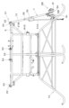
- FIG. 2 is a diagram showing the flying device according to the first embodiment with the arm rotated downward.
- FIG. 2 is a diagram showing the arms, sub-rotor, etc. of the flying device according to the first embodiment as viewed from above.
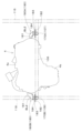
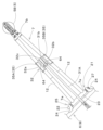
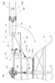
- FIG. 2 is a diagram showing the arms, sub-rotor, etc. of the flying device according to the first embodiment as viewed from a horizontal direction.
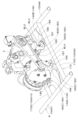
- FIG. 2 is a perspective view showing a pivot part and the like of the flying device according to the first embodiment.
- 2 is a diagram showing a state in which a first section and a second section of an arm are separated in the flying device according to the first embodiment.
- FIG. FIG. 2 is an exploded perspective view showing a switching mechanism and the like of the flying device according to the first embodiment.
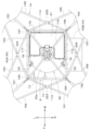
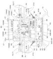
- FIG. 2 is a plan view showing the arrangement of engines of the flying device according to the first embodiment.
- FIG. 2 is a perspective view showing a main body and a first portion of an arm of the flying device according to the first embodiment.
- FIG. 2 is a plan view showing the positional relationship between the main rotor and a cooling device (radiator) of the flying device according to the first embodiment.
- FIG. 2 is a perspective view showing a cooling device (radiator), air guide members, etc. of the flying device according to the first embodiment.
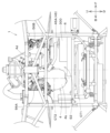
- FIG. 2 is an enlarged front view of the flying device according to the first embodiment.
- FIG. 2 is an enlarged rear view of the flying device according to the first embodiment.
- FIG. 2 is a perspective view showing a fuel tank, a casing, a skid, etc.
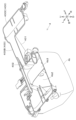
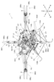
- FIG. 2 is a perspective view showing a cooling system for the flying device according to the first embodiment.
- FIG. 2 is a plan view showing the positional relationship between a fuel tank and a cooling system of the flight device according to the first embodiment.
- FIG. 2 is a perspective view of the engine as seen from the left front.
- FIG. 2 is a perspective view of the engine as seen from the right rear.
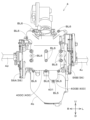
- FIG. 2 is a side view of the engine as seen from the right.
- FIG. FIG. 2 is a longitudinal cross-sectional view of the engine cut vertically at the intake passage (the upper part is omitted).
- FIG. 2 is a longitudinal cross-sectional view of the engine cut vertically at the exhaust passage (the upper part is omitted).
- FIG. 2 is a view of the engine from below and front.
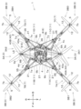
- FIG. 4 is a plan view of a flying device according to a second embodiment of the present invention.
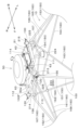
- FIG. 4 is a perspective view of a flying device according to a second embodiment of the present invention.
- FIG. 4 is a front view of a flying device according to a second embodiment of the present invention.
- FIG. 4 is a rear view of a flying device according to a second embodiment of the present invention.
- FIG. 5 is a left side view of a flying device according to a second embodiment of the present invention.
- FIG. 6 is a right side view of a flying device according to a second embodiment of the present invention.
- FIG. 11 is a plan view of the flying device according to the second embodiment, showing the rotation trajectories of the main rotor and the sub-rotor, etc.
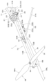
- FIG. 11 is a perspective view showing the arms, pivot parts, etc. of the flying device according to the second embodiment, as viewed obliquely from above. 13 is a bottom view of the arm, pivot part, connector (first support member), etc. of the flying device according to the second embodiment.
- FIG. FIG. 11 is a perspective view showing a main body and a pivot support of a flying device according to a second embodiment.
- FIG. 11 is a diagram showing the arms, sub-rotor, etc.
- the flying device 1 according to the present invention is an unmanned flying device. More specifically, the flying device 1 is a multicopter known as a drone. The flying device 1 may fly by remote control using wireless or wired communication, or it may fly by autonomous control without relying on a remote device.
- Figs. 1 to 23 are diagrams showing a first embodiment of the flying device 1.
- Figs. 1 to 6 are diagrams showing the overall configuration of the flying device 1 of the first embodiment.
- the direction indicated by arrow F in the figures will be referred to as the forward direction
- the direction indicated by arrow B as the rearward direction
- the direction indicated by arrow L as the leftward direction
- the direction indicated by arrow R as the rightward direction.
- the direction indicated by arrow U will be referred to as the upward direction
- the direction indicated by arrow D as the downward direction.
- the aircraft 2 has a main body 6 and a number of arms 7 extending from the main body 6.
- the main rotor 3A is attached to the main body 6.
- the sub-rotor 3B is attached to the arms 7.
- the main body 6 has a frame main body 8 and a protruding frame 9.
- the frame main body 8 is equipped with a drive unit 4 that drives the main rotor 3A.
- the drive unit 4 is an engine, a motor, or the like. In this embodiment, the drive unit 4 is an engine. Therefore, hereinafter, the drive unit 4 will be described as an engine 4.
- the frame body 8 is formed in a rectangular shape in a plan view.
- the frame body 8 is formed so as to surround the engine 4 in a plan view (see FIG. 7, etc.).
- the protruding frame 9 protrudes in a direction away from the frame body 8 in a plan view.
- the protruding frame 9 protrudes in the horizontal direction.
- the main rotor 3A is attached to the protruding frame 9. In other words, the main rotor 3A is attached to the main body 6 (protruding frame 9) rather than to the arm 7.
- the protruding frame 9 has a corner 9a at the tip in the protruding direction.
- the main rotor 3A is attached to the corner 9a of the protruding frame 9.
- the protruding frame 9 includes multiple frame members (see frame members 119-126 in FIG. 15) that extend in a direction away from the frame main body 8 and approach each other in the protruding direction to form the corner 9a.
- the corner 9a of the protruding frame 9 is located between adjacent arms 7 (see FIG. 1).
- the protruding frame 9 includes a first protruding frame 9A and a second protruding frame 9B.
- the first protruding frame 9A and the second protruding frame 9B protrude in opposite directions from the frame main body 8 in a plan view.
- the first protruding frame 9A protrudes to the left from the frame main body 8.
- the second protruding frame 9B protrudes to the right from the frame main body 8.
- first protruding frame 9A first protruding frame 9A, second protruding frame 9B
- members that make up the frame body 8 Note that here, of the members that make up the frame body 8, only those related to the protruding frame 9 will be mentioned, and the other members will be explained in detail later.
- the first protruding frame 9A is composed of upper frame materials (frame materials 119, 121) and lower frame materials (frame materials 120, 122).
- the upper and lower frame materials are connected to each other via the members that make up the frame main body 8 (frame materials 115, 117) and the first connector 145, which will be described later.
- the first protruding frame 9A is combined with the members that make up the frame main body 8 (frame materials 101, 105) to form a triangular shape in a plan view.
- the second protruding frame 9B is composed of upper frame materials (frame materials 123, 125) and lower frame materials (frame materials 124, 126).
- the upper and lower frame materials are connected to each other via the members constituting the frame main body 8 (frame materials 116, 118) and the second connector 146 described below.
- the second protruding frame 9B is combined with the members constituting the frame main body 8 (frame materials 102, 106) to form a triangular shape in a plan view.
- the arms 7 extend in a direction away from the main body 6 in a plan view.
- the arms 7 extend radially from the main body 6 in a plan view.
- the arms 7 extend in the horizontal direction.
- the number of arms 7 is four.
- the number of arms 7 may be five or more, or three or less.
- the flying device 1 of this embodiment is equipped with a first arm 7A, a second arm 7B, a third arm 7C, and a fourth arm 7D.
- the first arm 7A extends from the main body 6 to the front left.
- the second arm 7B extends from the main body 6 to the front right.
- the third arm 7C extends from the main body 6 to the rear left.
- the fourth arm 7D extends from the main body 6 to the rear right.
- the sub-rotors 3B are attached to the multiple arms 7.
- the sub-rotors 3B are attached to the tips of the arms 7.
- the base ends of the arms 7 are attached to the main body 6.
- the main rotors 3A are disposed between adjacent arms 7.
- the main rotor 3A is attached to the protruding frame 9 of the main body 6, and the sub-rotor 3B is attached to the arm 7.
- a rotor (main rotor 3A) separate from the rotor (sub-rotor 3B) attached to the arm 7 is attached to the protruding frame 9.
- the base end 7a of the arm 7 is attached (connected) to the protruding frame 9 of the main body 6.
- the arm 7 is connected to the portion between the base end (base end 9b) in the protruding direction of the protruding frame 9 and the corner 9a. More specifically, the arm 7 is connected to the portion between the base end 9b and the corner 9a of the protruding frame 9, at a position closer to the base end 9b than the corner 9a.
- each arm 7 has two base ends 7a, one of which is connected to the base end 9b of the protruding frame 9, and the other is connected to a position between the corner 9a and the base end 9b, closer to the base end 9b than the corner 9a.
- the base ends 7a of multiple (two) arms 7 are connected to one protruding frame 9.
- the base ends 7a of the first arm 7A and the third arm 7C are connected to the first protruding frame 9A.
- the base ends 7a of the second arm 7B and the fourth arm 7D are connected to the second protruding frame 9B.
- the aircraft body 2 has a protruding frame 9 to the tip of which the main rotor 3A is attached, and an arm 7 to the tip of which the sub-rotor 3B is attached.
- the protruding frame 9 is a first support part that supports the main rotor 3A to the aircraft body 2.
- the arm 7 is a second support part that supports the sub-rotor 3B to the aircraft body 2.
- the length L1 from the base end 9b of the protruding frame 9, which is the first support, to the tip end (corner 9a) is shorter than the length L2 from the base end 7a to the tip end 7b of the arm 7, which is the second support.
- length L1 is the length from the straight line connecting the two base ends 9b, 9b of the protruding frame 9 to the tip end (corner 9a).
- Length L2 is the length from the base end 7a, which is the one of the two base ends 7a, 7a of the arm 7 that is closer to the tip end 7b, to the tip end 7b.
- the width W1 of the base end 9b of the protruding frame 9, which is the first support, is greater than the width W2 of the base end 7a of the arm 7, which is the second support.
- the width W1 is the distance between the two base ends 9b, 9b of the protruding frame 9.
- the width W2 is the distance between the two base ends 7a, 7a of the arm 7.
- a skid 10 is attached to the lower part of the main body 6.
- the skid 10 has a number of legs 11 extending downward from the main body 6.
- the legs 11 touch the ground when the flying device 1 lands, and support the aircraft 2 by floating it above a landing surface such as the ground.
- the number of legs 11 is not particularly limited, but in this embodiment, there are four.
- the four legs 11 will be referred to as the first leg 11A, the second leg 11B, the third leg 11C, and the fourth leg 11D, respectively.
- the first sub-rotor 3B1 is attached to the tip of the first arm 7A and is located at the left front of the aircraft body 2.
- the second sub-rotor 3B2 is attached to the tip of the second arm 7B and is located at the right front of the aircraft body 2.
- the third sub-rotor 3B3 is attached to the tip of the third arm 7C and is located at the left rear of the aircraft body 2.
- the fourth sub-rotor 3B4 is attached to the tip of the fourth arm 7D and is located at the right rear of the aircraft body 2.
- the sub-rotor 3B includes a first rotor 3BU and a second rotor 3BL.
- the first rotor 3BU and the second rotor 3BL are arranged in a vertically overlapping position.
- the first rotor 3BU is attached above the arm 7.
- the second rotor 3BL is attached below the arm 7.
- the first rotor 3BU is located above the second rotor 3BL.
- the first rotor 3BU will be referred to as the upper rotor 3BU
- the second rotor 3BL will also be referred to as the lower rotor 3BL.
- the main rotor 3A is positioned lower than the first rotor (upper rotor) 3BU and the second rotor (lower rotor) 3BL.
- the main rotor 3A is positioned lower than both the first rotor (upper rotor) 3BU and the second rotor (lower rotor) 3BL.
- the vertical distance between the main rotor 3A and the second rotor (lower rotor) 3BL is smaller than the vertical distance between the first rotor (upper rotor) 3BU and the second rotor (lower rotor) 3BL.
- the length of the second portion 72 is longer than the length of the first portion 71. Specifically, the length of the second portion 72 is at least twice the length of the first portion 71. In addition, the maximum width of the first portion 71 (the width of the base end portion) is greater than the maximum width of the second portion 72.
- the machine body 2 has a pivot part 21 that supports the arm 7 so that it can rotate relative to the main body part 6.
- the pivot part 21 has a pivot shaft 22 and a retaining tube 23.
- the pivot shaft 22 is a cylindrical shaft that serves as a fulcrum for the rotation of the arm 7 and extends in the horizontal direction.
- the pivot shaft 22 extends perpendicular to the longitudinal direction of the arm 7.
- a first spacer 28A is disposed on the inside of the first shaft support portion 24A (the side closer to the second shaft support portion 24B).
- a second spacer 28B is disposed on the inside of the second shaft support portion 24B (the side closer to the first shaft support portion 24A).
- the first spacer 28A and the second spacer 28B can be made of a flexible material (rubber, soft resin, etc.).
- the first spacer 28A and the second spacer 28B each have a tube portion 28c and a flange portion 28d.
- the tube portion 28c is inserted inside the retaining tube 23.
- One surface of the flange portion 28d abuts against the end face of the retaining tube 23, and the other surface abuts against the inner surface of the shaft support portion 24.
- the aircraft 2 is equipped with a connector 31 that connects the main body 6 and the arm 7.
- the connector 31 is a straight member.
- the connector 31 extends diagonally upward from the main body 6 and is connected to the middle of the arm 7.
- the connector 31 is a member that is connected to the main body 6 and supports the arm 7 from below. By supporting the arm 7 from below, the connector 31 suppresses the vertical shaking of the arm 7.
- the multiple first rods 12A are spaced apart in the horizontal direction, and the first rods 12A and the second support member 31B are spaced apart in the vertical direction. Therefore, the plate 30 is supported by the main body 6 (protruding frame 9) with high strength in both the horizontal and vertical directions. This makes it possible to suppress both the vertical and horizontal oscillations of the plate 30, and therefore to suppress both the vertical and horizontal oscillations of the arm 7.
- Figure 25 shows only the components of an opposed piston engine that are relevant to the present invention, and does not show, for example, intake valves, exhaust valves, spark plugs, injection nozzles, etc.
- the first piston 81 and the second piston 82 are disposed opposite each other in the cylinder 80.
- the first crankshaft 83 is connected to the first piston 81 via a first connecting rod 85.
- the second crankshaft 84 is connected to the second piston 82 via a second connecting rod 86.
- the first piston 81 and the second piston 82 reciprocate within the cylinder 80. More specifically, the first piston 81 and the second piston 82 move in a direction away from or toward each other within the cylinder 80.
- the crankshaft rotates in conjunction with the reciprocating motion of the pistons.
- the first crankshaft 83 rotates in conjunction with the reciprocating motion of the first piston 81.
- the second crankshaft 84 rotates in conjunction with the reciprocating motion of the second piston 82.
- the first crankshaft 83 and the second crankshaft 84 rotate in opposite directions.
- the first generator 56A is connected to the other end of the first crankshaft 83.
- the second generator 56B is connected to the other end of the second crankshaft 84.
- the first generator 56A generates electricity by the rotation of the first crankshaft 83.
- the second generator 56B generates electricity by the rotation of the second crankshaft 84.
- the first output shaft 4c extends between the front and rear frame members (the 19th frame member 119 and the 21st frame member 121 (see FIG. 15) described later) that make up the first protruding frame 9A in a plan view.
- the second output shaft 4d extends between the front and rear frame members (the 23rd frame member 123 and the 25th frame member 125 (see FIG. 15) described later) that make up the second protruding frame 9B in a plan view.
- the presence of the first protruding frame 9A and the second protruding frame 9B makes it difficult to approach the first output shaft 4c and the second output shaft 4d from above. Therefore, before takeoff or after landing, etc., it is safe because it is possible to effectively prevent hands, clothing, etc. from coming into contact with the rotating first output shaft 4c and the second output shaft 4d.
- the engine body 4a is disposed at an angle to the frame body 8 in a plan view.
- the frame body 8 is formed into a rectangle in a plan view.
- the engine body 4a is disposed so that its longitudinal direction in a plan view is non-parallel to and non-perpendicular to the rectangular sides of the frame body 8.
- the frame body 8 has a first frame member 101 arranged on one side (left) of the engine 4, and a second frame member 102 arranged on the other side (right) of the engine 4. As shown in FIG. 15, the frame body 8 is constructed by combining a number of frame members. The frame members other than the first frame member 101 and the second frame member 102 will be described in detail later.
- first frame member 101 and the second frame member 102 are arranged parallel to each other.
- the first output shaft 4c extends at an angle relative to the first frame member 101 in a plan view.
- the second output shaft 4d extends at an angle relative to the second frame member 102 in a plan view.
- the first output shaft 4c and the first frame member 101 intersect at a non-right angle.
- the second output shaft 4d and the second frame member 102 intersect at a non-right angle.
- the multiple main rotors 3A include a first rotor 3A1 arranged on one side (left) of the engine 4 in a plan view, and a second rotor 3A2 arranged on the other side (right) of the engine 4.
- the first rotor 3A1 is the first main rotor 3A1
- the second rotor 3A2 is the second main rotor 3A2.
- the first output shaft 4c and the second output shaft 4d extend at an angle to a line L5 (see Figure 1) connecting the center of the first rotor 3A1 and the center of the second rotor 3A2 in a plan view.
- the first output shaft 4c supplies driving force to the one rotor 3A1.
- the second output shaft 4d supplies driving force to the other rotor 3A2.
- the rotation of the first output shaft 4c is transmitted to the rotating shaft 3c of the one rotor 3A1 via a first power transmission unit 38 (see Figures 3 and 4) consisting of a gear mechanism or the like. This causes the blades 3d of the one rotor 3A1 to rotate.
- the rotation of the second output shaft 4d is transmitted to the rotating shaft 3c of the other rotor 3A2 via a second power transmission unit 39 (see Figures 3 and 4) consisting of a gear mechanism or the like. This causes the blades 3d of the other rotor 3A2 to rotate.
- the two main rotors (the one rotor 3A1 and the other rotor 3A2) are driven by two output shafts (the first output shaft 4c and the second output shaft 4d) of one engine 4.
- the rotor 3 and the engine 4 overlap in the vertical direction.
- the rotor 3 and the engine 4 overlap in the vertical direction.
- the main rotor 3A and the engine 4 overlap in the vertical direction.
- the sub-rotor 3B and the engine 4 also overlap in the vertical direction.
- the flying device 1 is equipped with a cooling device 40 that water-cools the drive unit (engine 4) that drives the main rotor 3A.
- the cooling device 40 preferably includes a radiator.
- the cooling device 40 is a radiator 40.
- the cooling device 40 is not limited to a radiator.
- the radiator 40 water-cools the engine 4, but it may also water-cool the battery 46, or it may water-cool the engine 4 and the battery 46.
- the cooling device 40 is described as a radiator 40 that water-cools the engine 4 (cools the coolant for the engine 4).
- the radiator 40 is disposed below the blades 3d of the main rotor 3A.
- the radiator 40 is disposed on the sides (left and right) of the main body 6.
- the radiator 40 is located outside the main body 6 and protrudes in a direction away from the main body 6. More specifically, the radiator 40 is located outside the frame main body 8 and protrudes in a direction away from the frame main body 8 (horizontally). In this way, since the radiator 40 is located outside the frame main body 8, heat from the engine 4 and the like disposed inside the frame main body 8 is less likely to be transmitted to the radiator 40.
- the radiator 40 can be cooled by blowing air on it during flight. This improves the cooling effect of the radiator 40.
- the radiator 40 is formed in a roughly rectangular parallelepiped shape.
- the radiator 40 is oriented (horizontally) so that its vertical length is shorter than its front-rear and left-right lengths.
- the radiator 40 is attached to the lower part of the main body 6 by mounting fixtures 73.
- the mounting fixtures 73 are fixed to the eleventh and twelfth frame members 111 and 112 (see Figure 15) of the lower frame 100F of the main body 6, which will be described later. In this way, the radiator 40 is supported by the lower frame 100F of the main body 6.
- the radiator 40 is arranged with the heat dissipation surface 40a facing upward. As shown in Figure 16, the radiator 40 is arranged at a position that overlaps with the rotation trajectory R1 of the blades 3d of the main rotor 3A in a plan view. The heat dissipation surface 40a of the radiator 40 overlaps with the rotation trajectory R1 of the blades 3d of the main rotor 3A in a plan view.
- the radiator 40 includes a first radiator 40A and a second radiator 40B.
- the first radiator 40A and the second radiator 40B are arranged symmetrically on opposite sides of the main body 6.
- the first radiator 40A is arranged in a position overlapping the triangle formed by the first protruding frame 9A and the frame members 101, 105 (see FIG. 15) that constitute the frame main body 8 in a plan view.
- the second radiator 40B is arranged in a position overlapping the triangle formed by the second protruding frame 9B and the frame members 102, 106 (see FIG. 15) that constitute the frame main body 8 in a plan view. This effectively prevents foreign objects from colliding from above with the radiators (first radiator 40A, second radiator 40B) that are arranged to protrude from the frame main body 8.
- the first radiator 40A is arranged at a position overlapping the rotation trajectory of the blades 3d of the first main rotor 3A1 in a plan view.
- the second radiator 40B is arranged at a position overlapping the rotation trajectory of the blades 3d of the second main rotor 3A2 in a plan view.
- the flying device 1 is equipped with an air guide member 44 that guides the downward airflow generated by the rotation of the blades 3d of the main rotor 3A toward the radiator 40.
- the air guide member 44 is arranged so as to protrude outside the frame body 8.
- the air guide member 44 is arranged at a position overlapping the rotation trajectory R1 of the blades 3d of the main rotor 3A in a plan view.
- the air guide member 44 is arranged above the heat dissipation surface 40a of the radiator 40. The lower end of the air guide member 44 abuts against or is close to the heat dissipation surface 40a of the radiator 40.
- the air guide member 44 is attached to the top of the radiator 40 by a mounting fixture 74 such as a screw (see Figure 17).
- the air guide member 44 has a first plate 44a, a second plate 44b, and a third plate 44c.
- the first plate 44a and the second plate 44b are erected facing each other with a gap between them in the front-rear direction.
- the third plate 44c connects the first plate 44a and the second plate 44b.
- the air guide member 44 has an extension portion 45 in which the distance between the first plate 44a and the second plate 44b gradually increases as the distance increases upward.
- the distance between the upper end of the first plate 44a and the upper end of the second plate 44b is wider than the width (front-to-back distance) of the radiator 40. This ensures that the downward airflow generated by the rotation of the blades 3d of the main rotor 3A can be reliably taken in between the first plate 44a and the second plate 44b from the upper end of the air guide member 44 and guided toward the radiator 40.
- the width (length in the left-right direction) of the first plate 44a of the air guide member 44 gradually increases from top to bottom.
- the width (length in the left-right direction) of the second plate 44b also gradually increases from top to bottom.
- the width (length in the left-right direction) of the lower end portion, which is the widest part, of the first plate 44a and the second plate 44b is approximately the same as the width (length in the left-right direction) of the radiator 40. This makes it easier to take in the downward airflow generated by the rotation of the blades 3d of the main rotor 3A between the first plate 44a and the second plate 44b, and the taken-in airflow can be guided toward approximately the entire heat dissipation surface 40a of the radiator 40.
- an attachment portion 44d is provided on the upper portion of the air guide member 44 (the upper portion of the third plate 44c).
- the upper portion of the air guide member 44 is attached to the frame main body 8 via the attachment portion 44d.
- the frame main body 8 has frame members (fifth frame member 105, sixth frame member 106, seventh frame member 107, eighth frame member 108) that constitute the first middle frame 100D (see FIG. 15).
- the upper portion of the air guide member 44 is attached to the frame members (fifth frame member 105, sixth frame member 106) that constitute the first middle frame 100D.
- the lower frame 100F of the frame main body 8 and the first middle frame 100D are connected in the vertical direction via the radiator 40 and the air guide member 44. Since the radiator 40 and the air guide member 44 are disposed on the left and right sides of the frame main body 8, the lower frame 100F and the first middle frame 100D are connected in the vertical direction at the left and right parts of the frame main body 8. This improves the rigidity of the frame main body 8.
- the pump 66 circulates the cooling water between the engine 4 and the radiator 40.
- One end of a first pipe 67 is connected to the discharge port of the pump 66.
- the other end of the first pipe 67 is connected to the lower part of the engine 4.
- the other end of the first pipe 67 is connected to the lower part of the cooling jacket (not shown) of the engine 4.
- One end of a second pipe 68 is connected to the suction port of the pump 66.
- the other end of the second pipe 68 is connected to the cooling water outlet 40b of the radiator 40.
- the second pipe 68 branches into a branch pipe 68A and a branch pipe 68B in the middle, the branch pipe 68A is connected to the cooling water outlet 40b of the first radiator 40A, and the branch pipe 68B is connected to the cooling water outlet 40b of the second radiator 40B.
- one end of the third pipe 69 is connected to the top of the engine 4. Specifically, one end of the third pipe 69 is connected to the top of the cooling jacket (not shown) of the engine 4. The other end of the third pipe 69 is connected to the cooling water inlet 40c of the radiator 40. Specifically, the third pipe 69 branches into branch pipes 69A and 69B midway, and the branch pipe 69A is connected to the cooling water inlet 40c of the first radiator 40A, and the branch pipe 68B is connected to the cooling water inlet 40c of the second radiator 40B.
- the flying device 1 is equipped with a battery 46 that stores the power supplied to the motor 5.
- the battery 46 is disposed on one side (left) and the other side (right) of the engine 4 in a plan view.
- the two batteries 46 are disposed to sandwich the engine 4 in a plan view.
- the battery 46 overlaps with the oil pan 4b in the vertical direction.
- the battery 46 is located to the side of the oil pan 4b.
- the two batteries 46 are disposed on one side (left) and the other side (right) of the oil pan 4b, respectively.
- the height of the upper end of the battery 46 and the height of the lower end of the engine body 4a are approximately the same. In other words, the battery 46 hardly overlaps with the engine body 4a in the vertical direction. As a result, heat generated from the engine body 4a is not easily transmitted to the battery 46.
- the air guide member 44 is disposed opposite the surface of the battery 46 on the outer side of the aircraft body, the surface of the battery 46 on the outer side of the aircraft body is protected by the air guide member 44. This makes it possible to prevent foreign objects from colliding with the battery 46 during flight, etc.
- an oil pan 4b is provided below the engine block 400.
- the oil pan 4b is provided only on one side (the left side of the paper in Figure 31) of the engine block 400 in the width direction (front-rear direction).
- the side of the engine 4 where the oil pan 4b is provided protrudes downward further than the side where it is not provided (the right side of the paper in Figure 31).
- the lower end (bottom surface) of the engine 4 on the side where the oil pan 4b is provided is lower than the lower end (bottom surface) of the side where it is not provided.
- first crankshaft 83 and the second crankshaft 84 are arranged parallel to each other with a gap in between in the direction in which the first piston 81 and the second piston 82 are aligned. Note that the upper part of the engine 4 (the part above the wavy line) is omitted in Figures 33 and 34.
- the inclined portion 401 is provided on only a portion of the engine block 400 in the depth direction (left-right direction). Specifically, the inclined portion 401 is provided on one side (left side) of the engine block 400 in the depth direction perpendicular to the width direction. In other words, in this embodiment, the inclined portion 401 is provided on the left part of the engine block 400.
- the batteries 46 are located on the sides of the oil pan 4b.
- the two batteries 46 are disposed on one side (left) and the other side (right) of the oil pan 4b, respectively.
- Figure 37 only shows the battery (first battery 46A) disposed on one side (left) of the oil pan 4b.
- the radiator 40 and the air guide member 44 are omitted from Figure 37.
- the oil pan 4b of the engine 4 is provided on only one of the widthwise sides of the engine block 400. Therefore, a space S2 is created below the other widthwise side of the engine block 400 (the side where the oil pan 4b is not provided), and the electrical equipment 300 is arranged in this space S2. In this way, since the oil pan 4b of the engine 4 is provided only on one widthwise side of the engine block 400, space can be secured for arranging the electrical equipment 300 below the other widthwise side of the engine block 400.
- the oil pan 4b of the engine 4 is positioned offset horizontally (rearward) from the vertical central axis CT1 of the main body 6 on which the engine 4 is mounted.
- the engine 4 is positioned such that the vertical central axis CT2 of the oil pan 4b is eccentric to the vertical central axis CT1 of the main body 6.
- FIG. 24 is a block diagram showing the configuration of the flight device 1.
- the flight device 1 is equipped with a control device 55.
- the control device 55 controls the driving of the engine 4 and the motor 5.
- the control device 55 is disposed in the middle section 8C of the frame body 8 (see FIG. 18 and FIG. 19).
- the control device 55 is equipped with a calculation unit such as a CPU, and a storage unit such as a RAM or ROM.
- the driving of the engine 4 is controlled by a control signal transmitted from the control device 55.
- the generator 56 generates electricity by being driven by the driving force of the engine 4.
- the generator 56 includes the first generator 56A and the second generator 56B described above.
- the electric power generated by the first generator 56A is stored in one of the first battery 46A and the second battery 46B.
- the electric power generated by the second generator 56B is stored in the other of the first battery 46A and the second battery 46B.
- the flying device 1 is equipped with a positioning device 47, a camera 57, and a sensor 58.
- the positioning device 47 includes a GNSS sensor such as a GPS sensor, a compass, etc.
- the camera 57 acquires image information of the surroundings of the flying device 1.
- the sensors 58 include a gyro sensor 58A, an acceleration sensor 58B, an altitude sensor 58C, an obstacle sensor 58D, etc.
- the control device 55 controls the operation of the engine 4 and the motor 5 based on information input from the positioning device 47, the camera 57, the sensor 58, and the operating device 59.
- the operating device 59 transmits information (instructions) regarding the control of the flying device 1 wirelessly or via a wired connection.
- the control device 55 receives the information transmitted from the operating device 59 via the communication unit 60.
- the user of the flying device 1 can control the position, height, movement speed, movement direction, attitude, etc. of the flying device 1 from a position away from the flying device 1.
- the first middle frame 100D is composed of a fifth frame member 105, a sixth frame member 106, a seventh frame member 107, and an eighth frame member 108.
- the fifth frame member 105 extends in the front-to-rear direction below the first frame member 101.
- the sixth frame member 106 extends in the front-to-rear direction below the second frame member 102.
- the seventh frame member 107 extends diagonally from the front of the frame main body 8, moving rearward as it moves from the left to the right.
- the eighth frame member 108 extends diagonally from the rear of the frame main body 8, moving rearward as it moves from the left to the right.
- the seventh frame member 107 and the eighth frame member 108 are arranged parallel to each other.
- the protruding frame 9 is composed of multiple straight frame members 100.
- the frame members 100 (19th frame member 119 to 26th frame member 126) of the protruding frame 9 are connected to the frame members 100 (1st frame member 101 to 8th frame member 108, 15th frame member 115 to 18th frame member 118) that make up the frame main body 8 by joints 200 (1st joint 201 to 4th joint 204).
- the 21st frame member 121 is connected to the second joint 202 and extends from the second joint 202 toward the left front.
- the 22nd frame member 122 is connected to the 18th joint 218 and extends from the 18th joint 218 toward the left front.
- the 21st frame member 121 and the 22nd frame member 122 are arranged side by side with a gap in the vertical direction.
- the 21st frame member 121 extends horizontally.
- the 22nd frame member 122 extends at an angle so as to transition upward as it moves away from the frame main body 8. As a result, the vertical gap between the 21st frame member 121 and the 22nd frame member 122 becomes smaller as it moves away from the frame main body 8.
- the engine mount 180 has a first member 181, a second member 182, and a third member 183.
- the first member 181 is attached to the engine 4 by a fastener such as a bolt BL1.
- the second member 182 is attached to the pipe 170 (first pipe 170A).
- the second member 182 may be attached to the pipe 170 (first pipe 170A) by welding, adhesive, or the like, or may be attached by a fastener such as a bolt.
- the second member 182 and the pipe 170 may be attached in a non-detachable state or in a detachable state.
- the first member 181 connected to the engine 4 and the second member 182 connected to the first pipe 170A are connected via the third member 183. This allows the engine 4 to be supported on the first pipe 170A via the first engine mount 180A. The engine 4 is also supported on the second pipe 170B via the second engine mount 180B.
- the engine mount 180 can be adjusted in position along the axial direction of the pipe 170. Specifically, the first engine mount 180A can be adjusted in position along the axial direction of the first pipe 170A. The second engine mount 180B can be adjusted in position along the axial direction of the second pipe 170B.
- Figures 38 to 43 are diagrams showing the overall configuration of the flight device 1 of the second embodiment.
- the direction indicated by the arrow F in the figures will be referred to as the forward direction
- the direction indicated by the arrow B as the rearward direction
- the direction indicated by the arrow L as the leftward direction
- the direction indicated by the arrow R as the rightward direction.
- the main body 6 has a frame main body 8 and a protruding frame 9.
- the frame main body 8 is mounted with an engine 4, which is a drive unit that drives the main rotor 3A.
- the protruding frame 9 protrudes in a direction away from the frame main body 8 in a plan view.
- the protruding frame 9 protrudes in the horizontal direction.
- the main rotor 3A is attached to the protruding frame 9.
- the protruding frame 9 includes a first protruding frame 9A and a second protruding frame 9B. The first protruding frame 9A and the second protruding frame 9B protrude in opposite directions from each other, sandwiching the frame main body 8 therebetween.
- the first sub-rotor 3B1 and the third sub-rotor 3B3 are arranged to sandwich the first main rotor 3A1 in a plan view.
- the second sub-rotor 3B2 and the fourth sub-rotor 3B4 are arranged to sandwich the second main rotor 3A2 in a plan view.
- the center of the first main rotor 3A1 is closer to the center of the aircraft 2 than the line (straight line) L3 connecting the center of the first sub-rotor 3B1 and the center of the third sub-rotor 3B3.
- the center of the second main rotor 3A2 is closer to the center of the aircraft 2 than the line (straight line) L4 connecting the center of the second sub-rotor 3B2 and the center of the fourth sub-rotor 3B4.
- the length L1 from the base end 9b of the protruding frame 9, which is the first support, to the tip end (corner 9a) is shorter than the length L2 from the base end 7a to the tip end 7b of the arm 7, which is the second support.
- the width W1 of the base end 9b of the protruding frame 9, which is the first support is greater than the width W2 of the base end 7a of the arm 7, which is the second support.
- the specific configuration of the flying device 1 of the second embodiment will be explained below, focusing on the differences from the first embodiment, while also mentioning the points in common with the first embodiment.
- the arm 7 has a first portion 71 fixed to the main body 6 and a second portion 72 that can rotate relative to the first portion 71 (see Figures 9, 10, etc.).
- the pivot portion 21, which serves as the pivot point for the arm 7, is provided between the first portion 71 and the second portion 72 (see Figure 10, etc.).
- the arm 7 is a portion that can rotate as a whole relative to the main body 6 (see Figures 48 and 49).
- the pivot portion 21 is provided between the base end portion 7a of the arm 7 and the main body 6 (see Figure 38).
- the two rods 12 that make up the arm 7 approach each other as they move away from the main body 6.
- the distance between the two rods 12 narrows from the base end 7a to the tip end 7b of the arm 7.
- the tips of the two rods 12 are connected to each other.
- the sub-rotor 3B and motor 5 are attached to the part where the tips of the two rods 12 are connected to each other.
- the arm 7 By configuring the arm 7 from two rods 12 aligned horizontally, it is possible to suppress lateral vibration of the arm 7 when the sub-rotor 3B rotates. In addition, because the two rods 12 move closer to each other as they move away from the main body 6, the width of the arm 7 increases as it approaches the main body 6, suppressing lateral vibration of the base end of the arm 7 and effectively suppressing lateral vibration of the entire arm 7.
- the pivot support 24 is attached to the main body 6 (protruding frame 9).
- the arm 7 rotates relative to the main body 6 as the retaining tube 23 rotates around the axis of the pivot shaft 22 (see arrow Y2 in Figure 48).
- the retaining tube 23 and the pivot shaft 22 form the pivot part 21 that supports the arm 7 rotatably relative to the main body 6.
- a bracket 32 is attached to the middle of the length of the two rods 12.
- An end (second end 31b) of a connector 31 that connects the main body 6 and the arm 7 is connected to the bracket 32.
- the bracket 32 has a first side plate portion 32a, a second side plate portion 32b and an upper plate portion 32c.
- the first side plate portion 32a, the second side plate portion 32b and the upper plate portion 32c are formed by bending a single plate (metal plate).
- Electrical equipment (inverter) 35 is attached to the inner surface of the first side plate portion 32a and the inner surface of the second side plate portion 32b, respectively.
- a first inverter 35A is attached to the inner surface of the first side plate portion 32a.
- a second inverter 35B is attached to the inner surface of the second side plate portion 32b.
- the electrical equipment (inverter 35) is positioned so as to overlap the bracket 32 in the length direction of the arm 7.
- the first inverter 35A and the second inverter 35B are positioned with a gap between them in the width direction of the arm 7.
- the bracket 32 has a portion to which the electrical equipment (inverter) 35 is attached and a portion to which the first support member 31A is connected. Therefore, the parts for attaching the electrical equipment 35 and the parts for connecting the first support member 31A are integrated into a single part (bracket 32). This makes it possible to reduce the number of parts, making the flying device 1 lighter.
- the blades (first blade 3f, second blade 3h) of the sub rotor 3B and the electrical equipment (inverter 35) are positioned so that they overlap in the vertical direction. This allows the electrical equipment (inverter 35) to be cooled by the downward airflow generated by the rotation of the blades (first blade 3f, second blade 3h). This makes it possible to prevent the electrical equipment (inverter 35) from overheating during flight.
- the engine 4 is arranged with the intake port 4e facing to the side and the exhaust port 4f facing upward.
- the intake port 4e is connected to the air cleaner 36 via a first connecting pipe 61.
- the exhaust port 4f is connected to the muffler 37 via a second connecting pipe 62.
- the air cleaner 36 is arranged vertically (with its longitudinal direction facing up and down) inside the frame main body 8 (inner corner).
- the muffler 37 is arranged sideways (with its longitudinal direction facing horizontally) so as to protrude outside the frame main body 8.
- the muffler 37 is fixed to the frame main body 8 so as to face in the front-to-rear direction.
- the muffler 37 is attached to the frame main body 8 by a mounting member 75.
- the mounting member 75 is attached to the fourth horizontal frame member 100A4 (see Figure 47) of the upper frame 100C described below.
- the rotor 3 and the engine 4 overlap in the vertical direction. More specifically, the main rotor 3A and the engine 4 overlap in the vertical direction. In addition, the sub-rotor 3B and the engine 4 overlap in the vertical direction. This makes the height of the center of gravity of the main body 6, on which the heavy engine 4 is mounted, roughly the same as the height of the rotor 3, thereby stabilizing the attitude of the flying device 1 during flight.
- the first output shaft 4c of the engine 4 extends between the front and rear frame members constituting the first protruding frame 9A (the first protruding frame member 9A1 and the second protruding frame member 9A2 (see FIG. 47) described later) in a plan view.
- the second output shaft 4d extends between the front and rear frame members constituting the second protruding frame 9B (the third protruding frame member 9B1 and the fourth protruding frame member 9B2 (see FIG. 47) described later) in a plan view.
- the presence of the first protruding frame 9A and the second protruding frame 9B makes it difficult to approach the first output shaft 4c and the second output shaft 4d from above. Therefore, before takeoff or after landing, etc., it is safe because it is possible to effectively prevent hands, clothing, etc. from coming into contact with the rotating first output shaft 4c and the second output shaft 4d.
- the second embodiment there is one radiator (cooling device) 40.
- the one radiator 40 is disposed below one of the two main rotors 3A (the first main rotor 3A1). As shown in FIG. 51, the one radiator 40 is disposed at a position overlapping with the rotation trajectory R1 of the blades 3d of the first main rotor 3A1 in a plan view.
- the air guide member 44 is also disposed at a position overlapping with the rotation trajectory R1 of the blades 3d of the first main rotor 3A1 in a plan view.
- a radiator fan 49 is disposed below the radiator 40.
- the radiator fan 49 generates a downward airflow that passes through the radiator 40. This allows the radiator 40 to be efficiently cooled by both the airflow generated by the rotation of the blades 3d of the first main rotor 3A1 and the airflow generated by the rotation of the radiator fan 49.
- the air guide member 44 has a first plate 44a, a second plate 44b, and a third plate 44c, as in the first embodiment.
- the air guide member 44 has an extension portion 45 in which the distance between the first plate 44a and the second plate 44b gradually increases as the distance increases upward.
- the distance between the upper end of the first plate 44a and the upper end of the second plate 44b is wider than the width (front-to-back distance) of the radiator 40.
- the distance between the lower end of the first plate 44a and the lower end of the second plate 44b is approximately the same as the width (front-to-back distance) of the heat dissipation surface 40a of the radiator 40.
- the upper end of the air guide member 44 is positioned below the blades 3d of the main rotor 3A. This allows the downward airflow generated by the rotation of the blades 3d of the main rotor 3A to be guided downward by the air guide member 44, and also allows a portion of the airflow to be guided from above the air guide member 44 into the inside of the frame body 8 to cool the equipment inside.
- the first battery 46A and the second battery 46B are disposed below the engine 4.
- the first battery 46A and the second battery 46B are disposed side by side in the left-right direction.
- the first battery 46A, the second battery 46B, and the control device 55 are disposed side by side in the left-right direction.
- the main body 6 is composed of multiple frame materials 100.
- the main body 6 is composed of multiple frame materials 100 connected by joints 200, but in the second embodiment, the main body 6 is composed of multiple frame materials 100 welded together.
- the frame main body 8 of the main body 6 is composed of multiple straight frame materials 100 combined into a three-dimensional shape (approximately rectangular parallelepiped shape).
- the frame materials 100 are composed of cylindrical pipes.
- the frame members 100 constituting the frame body 8 include horizontal frame members 100A extending horizontally and vertical frame members 100B extending vertically.
- the horizontal frame members 100A include the first horizontal frame member 100A1 to the fourteenth horizontal frame member 100A14.
- the horizontal frame members 100A constitute the upper frame 100C, the first middle frame 100D, the second middle frame 100E, and the lower frame 100F. From the top to the bottom of the frame body 8, the upper frame 100C, the first middle frame 100D, the second middle frame 100E, and the lower frame 100F are arranged in this order.
- the upper stage 8B of the frame main body 8 is formed between the upper frame 100C and the first middle frame 100D.
- the engine 4 and other components are arranged in the upper stage 8B.
- the middle stage 8C of the frame main body 8 is formed between the first middle frame 100D and the second middle frame 100E.
- the battery 46, control device 55, and other components are arranged in the middle stage 8C.
- the lower stage 8D of the frame main body 8 is formed between the second middle frame 100E and the lower frame 100F.
- the fuel tank 50, pump 66, and other components are arranged in the lower stage 8D.
- the flying device 1 of the second embodiment is equipped with a cooling system 90 that water-cools the drive unit (engine) 4, similar to the first embodiment.
- the cooling system 90 has a pump 66 and a cooling device (radiator) 40.
- the pump 66 circulates cooling water between the engine 4 and the radiator 40, similar to the first embodiment.
- the pump 66 is disposed in the lower part of the main body 6 (lower part of the frame main body 8).
- the pump 66 is disposed below the engine 4.
- the pump 66 is disposed below the radiator 40.
- the cooling system 90 has connecting pipes consisting of a first pipe 67 that connects the discharge port of the pump 66 to the engine 4, a second pipe 68 that connects the suction port of the pump 66 to the radiator 40, and a third pipe 69 that connects the engine 4 to the radiator 40.
- the lower end of the pump 66 is located below the engine 4, the radiator 40, and the connecting pipes.
- the upper frame 100C is composed of a first horizontal frame member 100A1, a second horizontal frame member 100A2, a third horizontal frame member 100A3, a fourth horizontal frame member 100A4, a fifth horizontal frame member 100A5, and a sixth horizontal frame member 100A6.
- the first horizontal frame member 100A1 extends in the front-to-rear direction on the left side of the frame main body 8.
- the second horizontal frame member 100A2 extends in the front-to-rear direction on the right side of the frame main body 8.
- the third horizontal frame member 100A3 extends left-right at the front of the frame body 8.
- the fourth horizontal frame member 100A4 extends left-right at the rear of the frame body 8.
- the third horizontal frame member 100A3 is located forward of the seventh horizontal frame member 100A7, which will be described later.
- the fourth horizontal frame member 100A4 is located rearward of the sixth horizontal frame member 100A6, which will be described later.
- the fifth horizontal frame member 100A5 extends in the left-right direction and connects the midpoint of the first horizontal frame member 100A1 in the fore-aft direction to the midpoint of the second horizontal frame member 100A2 in the fore-aft direction.
- the sixth horizontal frame member 100A6 extends in the left-right direction and connects the midpoint of the first horizontal frame member 100A1 in the fore-aft direction to the midpoint of the second horizontal frame member 100A2 in the fore-aft direction behind the fifth horizontal frame member 100A5.
- the ninth horizontal frame member 100A9 extends diagonally on the left side of the frame body 8, transitioning to the right as it moves from the front to the rear.
- the tenth horizontal frame member 100A10 extends diagonally on the right side of the frame body 8, transitioning to the right as it moves from the front to the rear.
- the ninth horizontal frame member 100A9 and the tenth horizontal frame member 100A10 are arranged parallel to each other.
- the front end of the ninth horizontal frame member 100A9 is connected to the seventh horizontal frame member 100A7.
- the rear end of the ninth horizontal frame member 100A9 is connected to the eighth horizontal frame member 100A8.
- the front end of the tenth horizontal frame member 100A10 is connected to the seventh horizontal frame member 100A7.
- the rear end of the tenth horizontal frame member 100A10 is connected to the eighth horizontal frame member 100A8.
- the vertical frame members 100B include a first vertical frame member 100B1 to a fourth vertical frame member 100B4.
- the first vertical frame member 100B1 extends vertically at the left front portion of the frame body 8.
- the second vertical frame member 100B2 extends vertically at the right front portion of the frame body 8.
- the third vertical frame member 100B3 extends vertically at the left rear portion of the frame body 8.
- the fourth vertical frame member 100B4 extends vertically at the right rear portion of the frame body 8.
- the upper end of the third vertical frame member 100B3 is connected to the first horizontal frame member 100A1 behind the first vertical frame member 100B1.
- the lower end of the third vertical frame member 100B3 is connected to the left part of the fourteenth horizontal frame member 100A14.
- the upper end of the fourth vertical frame member 100B4 is connected to the second horizontal frame member 100A2 behind the second vertical frame member 100B2.
- the lower end of the fourth vertical frame member 100B4 is connected to the right part of the fourteenth horizontal frame member 100A14.
- the left end of the seventh horizontal frame member 100A7 is connected to the vertical midpoint of the first vertical frame member 100B1.
- the right end of the seventh horizontal frame member 100A7 is connected to the vertical midpoint of the second vertical frame member 100B2.
- the left end of the eighth horizontal frame member 100A8 is connected to the vertical midpoint of the third vertical frame member 100B3.
- the right end of the eighth horizontal frame member 100A8 is connected to the vertical midpoint of the fourth vertical frame member 100B4.
- the lower frame 100G1 has a first lower frame member 100G3, a second lower frame member 100G4, and a connecting plate 100G5.
- the first lower frame member 100G3 and the second lower frame member 100G4 are formed in an arch shape.
- the first lower frame member 100G3 is attached to the first horizontal frame member 100A1.
- the second lower frame member 100G4 is attached to the second horizontal frame member 100A2.
- the connecting plate 100G5 connects the upper part of the first lower frame member 100G3 and the upper part of the second lower frame member 100G4.
- a positioning device 47 is attached to the top of the upper frame 100G2.
- the positioning device 47 is attached to each of the first upper frame member 100G6 and the second upper frame member 100G7.
- a flight controller 48 is attached to the top of the lower frame 100G1.
- the flight controller 48 is attached to the connecting plate 100G5.
- a reserve tank 65 is attached to the side of the lower frame 100G1.
- the reserve tank 65 is attached to the second lower frame member 100G4.
- the protruding frame 9 is formed integrally with the frame body 8.
- the protruding frame 9 was connected to the frame body 8 by a joint 200, but in the second embodiment, the protruding frame 9 is formed integrally with the frame body 8 without a joint.
- the third protruding frame member 9B1 and the fourth protruding frame member 9B2 approach each other as they move away from the frame body 8.
- the right end of the third protruding frame member 9B1 and the right end of the fourth protruding frame member 9B2 are connected to the second connector 146.
- the second main rotor 3A2 is attached to the second connector 146 (see FIG. 39).
- the vertical midpoint of the first vertical frame member 100B1 and the first protruding frame member 9A1 are connected by a first diagonal member 9C1.
- the vertical midpoint of the third vertical frame member 100B3 and the second protruding frame member 9A2 are connected by a second diagonal member 9C2.
- the vertical midpoint of the second vertical frame member 100B2 and the third protruding frame member 9B1 are connected by a third diagonal member 9C3.
- the vertical midpoint of the fourth vertical frame member 100B4 and the fourth protruding frame member 9B2 are connected by a fourth diagonal member 9C4.
- the first diagonal member 9C1 to the fourth diagonal member 9C4 are second support members 31B (see Figures 40 to 43) that support the arm 7 on the main body 6 side of the pivot part 21.
- the second support member 31B directly supports the arm 7, but in the second embodiment, the second support members 31B (the first diagonal member 9C1 to the fourth diagonal member 9C4) indirectly support the arm 7 via the protruding frame 9.
- the skid 10 includes a front skid 10A and a rear skid 10B.
- the front skid 10A has an upper front portion 10a extending in the left-right direction, a left front portion 10b extending downward from the left end of the upper front portion 10a, and a right front portion 10c extending downward from the right end of the upper front portion 10a.
- the upper front portion 10a is connected to the 13th horizontal frame member 100A13 (see Figure 47) of the frame body 8.
- the rear skid 10B has a rear upper portion 10d extending in the left-right direction, a rear left portion 10e extending downward from the left end of the rear upper portion 10d, and a rear right portion 10f extending downward from the right end of the rear upper portion 10d.
- the rear upper portion 10d is connected to the 14th horizontal frame member 100A14 (see FIG. 47) of the frame body 8.
- the front skid 10A has a front connector 191 that connects the front left section 10b and the front right section 10c.
- the rear skid 10B has a rear connector 192 that connects the rear left section 10e and the rear right section 10f.
- the front left portion 10b of the front skid 10A and the rear left portion 10e of the rear skid 10B are connected by a first left connector 193, a second left connector 194, and a third left connector 195.
- the first left connector 193 and the second left connector 194 cross each other halfway.
- the first left connector 193 connects the lower portion of the front left portion 10b to the upper portion of the rear left portion 10e.
- the second left connector 194 connects the upper portion of the front left portion 10b to the lower portion of the rear left portion 10e.
- the third left connector 195 connects the lower portion of the front left portion 10b to the lower portion of the rear left portion 10e.
- the front right portion 10c of the front skid 10A and the rear right portion 10f of the rear skid 10B are connected by a first right connecting member 196, a second right connecting member 197, and a third right connecting member 198.
- the first right connecting member 196 and the second right connecting member 197 cross each other halfway.
- the first right connecting member 196 connects the upper portion of the front right portion 10c to the lower portion of the rear right portion 10f.
- the second right connecting member 197 connects the lower portion of the front right portion 10c to the upper portion of the rear right portion 10f.
- the third right connecting member 198 connects the lower portion of the front right portion 10c to the lower portion of the rear right portion 10f.
- the engine mount 180 is attached to the pipe 170 via a connecting plate 149 arranged below the engine 4.
- the connecting plate 149 includes a first connecting plate 149A and a second connecting plate 149B.
- the first connecting plate 149A and the second connecting plate 149B are arranged at a distance from each other in the axial direction of the third pipe 170C and the fourth pipe 170D.
- the first connecting plate 149A connects the seventh horizontal frame member 100A7, the third pipe 170C (the ninth horizontal frame member 100A9), and the fourth pipe 170D (the tenth horizontal frame member 100A10).
- the second connecting plate 149B connects the eighth horizontal frame member 100A8, the third pipe 170C (the ninth horizontal frame member 100A9), and the fourth pipe 170D (the tenth horizontal frame member 100A10).
- the cooling device (radiator) 40 may be configured to water-cool the battery 46 in addition to the engine 4.
- the pump 66 circulates cooling water between the engine 4 and the cooling device (radiator) 40, and between the inside (or near the outside) of the battery 46 and the cooling device 40. Therefore, the pump 66, the cooling device (radiator) 40, and the engine 4, and the pump 66, the cooling device (radiator) 40, and the inside (or near the outside) of the battery 46 are each connected by piping for circulating the cooling water.
- the arm 7 has a base end 7a attached to the main body 6 and a rotor 3 attached to a tip end 7b, and the spacing between the multiple rods 12 narrows from the base end 7a to the tip end 7b.
- the flying device 1 also includes a stopper 30 that prevents the arm 7 from rotating upward beyond a predetermined position.
- the arm 7 has a first portion 71 fixed to the main body 6 and a second portion 72 that is rotatable relative to the first portion 71 and has a rotor 3 attached thereto.
- the stopper 30 is a plate that is disposed between the first portion 71 and the second portion 72, and the second support member 31B is connected to the plate 30.
- the engine body 4a can be housed within the frame body 8, making it possible to reduce the size of the frame body 8 on which the engine 4 is mounted.
- the main body 6 is made up of multiple straight frame members 100 and joints 200 that connect the frame members 100 together, it is easy to change the shape of the main body 6 depending on the type and size of the equipment to be mounted on the main body 6. In addition, the weight of the main body 6 can be reduced. Furthermore, since the main body 6 has high breathability, it is possible to prevent the various equipment mounted on the main body 6 from overheating.
- the arm 7 also has a straight rod 12, which is connected to the frame material 100 by a joint 200.
- the arm 7 also has multiple rods 12 arranged in a horizontal line, and each of the multiple rods 12 is connected to the frame material 100 by a joint 200.
- This configuration improves the strength of the arm 7 against horizontal forces and increases the connection strength between the arm 7 and the main body 6.
- the flying device 1 is equipped with an engine 4 that supplies driving force to the rotor 3, and the main body 6 has a frame body 8 on which the engine 4 is mounted, and the frame body 8 is configured by combining multiple straight frame members 100 into a three-dimensional shape with joints 200.
- the main body 6 also has a protruding frame 9 that protrudes from the frame main body 8 and to which a rotor 3 other than the rotor 3 attached to the arm 7 is attached.
- the protruding frame 9 is made up of multiple straight frame members 100, and the frame members 100 of the protruding frame 9 are connected to the frame members 100 that constitute the frame main body 8 by joints 200.
- This configuration allows the weight of the protruding frame 9, on which a rotor 3 other than the rotor 3 attached to the arm 7 is attached, to be reduced, and allows the protruding frame 9 to be easily and reliably connected to the frame body 8.
- the arm 7 also has a straight rod 12, which is connected to the frame material 100 that constitutes the protruding frame 9 by a joint 200.
- This configuration makes it easy to form a skid 10 with a shape and size that matches the shape and weight of the main body 6.
- the joint 200 has multiple connection ports 200a, and the ends of the frame material 100 are inserted into the connection ports 200a.
- D the inner diameter of the connection port 200a
- L the insertion length of the frame material 100 into the connection port 200a
- This configuration allows the joint 200 and the frame material 100 to be securely connected, and also provides high strength to the connection between the joint 200 and the frame material 100.
- the frame material 100 is also made of a magnesium alloy.
- the frame material 100 is made of a high-strength, lightweight material, so the main body 6 can be made to be high-strength and lightweight.
- the flying device 1 also includes an airframe 2, a rotor (main rotor 3A) attached to the airframe 2, a drive unit 4 that drives the rotor (main rotor 3A), and a cooling device 40 that water-cools the drive unit 4, and the cooling device 40 is disposed below the blades 3d of the rotor (main rotor 3A).
- the downward airflow generated by the drive of the rotor (main rotor 3A) can be directed at the cooling device 40. This allows the cooling device 40 to be cooled efficiently.
- the drive unit also includes an engine 4, and the cooling device 40 includes a radiator 40, which is disposed below the blades 3d of the rotor (main rotor 3A).
- the downward airflow generated by the drive of the rotor 3 can be directed toward the radiator 40. This allows the radiator 40 to be cooled efficiently.
- the cooling device 40 is also positioned so that it overlaps with the rotation trajectory R1 of the blade 3d in a plan view.
- the downward airflow generated by the rotation of the blades 3d of the rotor 3 can be more reliably directed at the cooling device 40.
- the cooling device 40 can be cooled very efficiently.
- the flying device 1 also includes a wind guide member 44 that guides the downward airflow generated by the rotation of the blades 3d toward the radiator 40.
- the downward airflow generated by the rotation of the blade 3d can be guided toward the cooling device 40 by the air guide member 44, so that the airflow can be reliably directed toward the cooling device 40.
- the air guide member 44 is positioned so that it overlaps with the rotation trajectory R1 of the blade 3d in a plan view.
- This configuration ensures that the downward airflow generated by the rotation of the blade 3d can be guided toward the air guide member 44.
- the upper end of the air guide member 44 is positioned above the blade 3d.
- the air guide member 44 also has a first plate 44a and a second plate 44b that are erected facing each other with a gap between them, and a third plate 44c that connects the first plate 44a and the second plate 44b.
- This configuration allows the downward airflow to be smoothly guided along the space surrounded by the first plate 44a, the second plate 44b, and the third plate 44c of the air guide member 44.
- the downward airflow generated by the rotation of the blade 3d can be reliably taken in between the first plate 44a and the second plate 44b from the expanded upper end of the air guide member 44 and directed toward the cooling device 40.
- the rotor 3 includes a first rotor 3A1 arranged on one side of the engine 4 and a second rotor 3A2 arranged on the other side of the engine 4 in a plan view, and is arranged in the following order in the horizontal direction: first rotor 3A1, first battery 46A, engine 4, second battery 46B, and second rotor 3A2.
- the first battery 46A, the second battery 46B, and the engine 4 are positioned between the first rotor 3A1 and the second rotor 3A2 in a well-balanced weight arrangement, allowing the flying device 1 to fly stably.
- This configuration prevents heat generated by the battery 46 from being transferred to the radiator 40.
- the flying device 1 also includes an air guide member 44 that guides the downward airflow generated by the rotation of the rotor 3 toward the radiator 40, and the air guide member 44 is arranged horizontally alongside the battery 46.
- the flying device 1 also includes a control device 55 that controls the operation of the engine 4 and the motor 5, and the control device 55 is disposed in the middle section 8C of the frame body 8.
- control device 55 is placed in the middle section 8C of the frame body 8, so that wiring and other connections between the control device 55 and other devices placed above or below it can be made over short distances.
- the fuel tank 50 is surrounded by a casing 51.
- the casing 51 can protect the fuel tank 50 from the surroundings, preventing the fuel tank 50 from being damaged by external forces from the surroundings.
- Fuel tank 50 also has a truncated cone-shaped lower portion 50a whose diameter decreases toward the bottom, and casing 51 is positioned to surround lower portion 50a of fuel tank 50.
- the lower portion 50a of the fuel tank 50 can be enclosed and protected without enlarging the size of the casing 51.
- the lower portion 50a of the fuel tank 50 is frustum shaped, fuel can be smoothly removed from the fuel tank 50 even if the aircraft 2 tilts during flight of the flying device 1.
- the protruding frame 9 also includes multiple frame members 100 that extend away from the frame body 8 and approach each other in the protruding direction to form corners 9a, the main rotor 3A is attached to the corners 9a, and the arm 7 is connected to the portion between the base end 9b of the protruding frame 9 and the corners 9a.
- This configuration allows the cooling water to flow smoothly and evenly between one pump 66 and two radiators (first radiator 40A, second radiator 40B).
- the flying device 1 also includes a fuel tank 50 that stores fuel to be supplied to the engine 4.
- the fuel tank 50 has a truncated cone-shaped lower portion 50a whose diameter decreases toward the bottom. At least a portion of the cooling system 90 is positioned so as to overlap the fuel tank 50 in a plan view, and its vertical position overlaps with the lower portion 50a of the fuel tank 50.
- This configuration makes it possible to secure space below the second crankshaft 84 side of the engine 4 for arranging other equipment.
- the inclined portion 401 is provided on one side of the engine block 400 in the depth direction perpendicular to the width direction.
- the inclined portion 401 is formed with a U-shaped cross section.
- This configuration allows the oil that has accumulated inside the inclined portion 401 to flow quickly and reliably toward the oil pan 4b.
- the inclined portion 401 can be made small, allowing the engine 4 to be made smaller.
- This configuration allows electrical equipment and other devices to be placed in the space S2 created below the other side of the engine 4 in the width direction, making it possible to make the flying device 1 compact.
- the flying device 1 also includes electrical equipment 300 mounted on the main body 6, which is located below the engine 4 and on the other side of the engine block 400 in the width direction, and its vertical position overlaps with the oil pan 4b.
- the flying device 1 also includes a motor 5 that supplies driving force to the rotor 3, and a battery 46 that stores the power supplied to the motor 5, and the electrical equipment 300 is a battery controller that controls the battery 46.
- This configuration allows the battery controller 300 that controls the battery 46 and the engine 4 to be placed close together in a compact manner in the flight device 1.
Landscapes
- Engineering & Computer Science (AREA)
- Aviation & Aerospace Engineering (AREA)
- Mechanical Engineering (AREA)
- Remote Sensing (AREA)
- Chemical & Material Sciences (AREA)
- Combustion & Propulsion (AREA)
- Toys (AREA)
Priority Applications (4)
| Application Number | Priority Date | Filing Date | Title |
|---|---|---|---|
| PCT/JP2022/048085 WO2024142200A1 (ja) | 2022-12-27 | 2022-12-27 | 飛行装置 |
| EP22969994.7A EP4644274A1 (en) | 2022-12-27 | 2022-12-27 | Flying apparatus |
| JP2024566985A JPWO2024142200A1 (https=) | 2022-12-27 | 2022-12-27 | |
| US19/250,651 US20250320003A1 (en) | 2022-12-27 | 2025-06-26 | Flying apparatus |
Applications Claiming Priority (1)
| Application Number | Priority Date | Filing Date | Title |
|---|---|---|---|
| PCT/JP2022/048085 WO2024142200A1 (ja) | 2022-12-27 | 2022-12-27 | 飛行装置 |
Related Child Applications (1)
| Application Number | Title | Priority Date | Filing Date |
|---|---|---|---|
| US19/250,651 Continuation US20250320003A1 (en) | 2022-12-27 | 2025-06-26 | Flying apparatus |
Publications (1)
| Publication Number | Publication Date |
|---|---|
| WO2024142200A1 true WO2024142200A1 (ja) | 2024-07-04 |
Family
ID=91717001
Family Applications (1)
| Application Number | Title | Priority Date | Filing Date |
|---|---|---|---|
| PCT/JP2022/048085 Ceased WO2024142200A1 (ja) | 2022-12-27 | 2022-12-27 | 飛行装置 |
Country Status (4)
| Country | Link |
|---|---|
| US (1) | US20250320003A1 (https=) |
| EP (1) | EP4644274A1 (https=) |
| JP (1) | JPWO2024142200A1 (https=) |
| WO (1) | WO2024142200A1 (https=) |
Citations (4)
| Publication number | Priority date | Publication date | Assignee | Title |
|---|---|---|---|---|
| WO2015029093A1 (ja) * | 2013-08-28 | 2015-03-05 | Kurihara Hidehiro | 水平対向エンジン |
| CN206243467U (zh) * | 2016-11-18 | 2017-06-13 | 中国航空工业集团公司沈阳飞机设计研究所 | 一种四涵道旋翼无人机 |
| JP2017154654A (ja) | 2016-03-03 | 2017-09-07 | 双葉電子工業株式会社 | マルチコプター |
| JP6979251B1 (ja) * | 2021-10-07 | 2021-12-08 | 株式会社石川エナジーリサーチ | 飛行装置 |
Family Cites Families (29)
| Publication number | Priority date | Publication date | Assignee | Title |
|---|---|---|---|---|
| US1545198A (en) * | 1924-06-05 | 1925-07-07 | Rietti Giacomo | Aircraft |
| US1957813A (en) * | 1931-02-20 | 1934-05-08 | Wilford Edward Burke | Aircraft |
| US2372926A (en) * | 1943-11-22 | 1945-04-03 | William K M Bartsch | Flying machine |
| US2738146A (en) * | 1953-02-19 | 1956-03-13 | Nicholas J Medvedeff | Convertiplane |
| US3002712A (en) * | 1957-02-01 | 1961-10-03 | Beckwith Sterling | Polycopter |
| US3526373A (en) * | 1957-10-04 | 1970-09-01 | Frank W Mclarty | Rotary winged aircraft |
| US3273653A (en) * | 1957-10-04 | 1966-09-20 | Frank W Mclarty | Rotary wing aircraft |
| US3053480A (en) * | 1959-10-06 | 1962-09-11 | Piasecki Aircraft Corp | Omni-directional, vertical-lift, helicopter drone |
| US3591109A (en) * | 1966-06-29 | 1971-07-06 | Frank W Mclarty | Rotary wing aircraft |
| US4856732A (en) * | 1987-05-01 | 1989-08-15 | Karl Eickmann | Airborne vehicle with hydraulic drive and control |
| US4874291A (en) * | 1987-05-25 | 1989-10-17 | University Of Sydney | Rotor arrangement for a rotorcraft |
| US5823468A (en) * | 1995-10-24 | 1998-10-20 | Bothe; Hans-Jurgen | Hybrid aircraft |
| US7472863B2 (en) * | 2004-07-09 | 2009-01-06 | Steve Pak | Sky hopper |
| DE102008014853B4 (de) * | 2008-03-18 | 2010-11-18 | Ascending Technologies Gmbh | Drehflügelfluggerät |
| US9663237B2 (en) * | 2012-02-22 | 2017-05-30 | E-Volo Gmbh | Aircraft |
| US20160272310A1 (en) * | 2014-12-04 | 2016-09-22 | Elwha Llc | Reconfigurable unmanned aircraft system |
| US9919797B2 (en) * | 2014-12-04 | 2018-03-20 | Elwha Llc | System and method for operation and management of reconfigurable unmanned aircraft |
| US10017245B2 (en) * | 2015-04-13 | 2018-07-10 | David Geise | Multirotor flying vehicle |
| CN108473198A (zh) * | 2015-09-03 | 2018-08-31 | 乔伊·音·陈 | 多转子旋翼飞机飞行器 |
| US10065726B1 (en) * | 2016-05-13 | 2018-09-04 | Top Flight Technologies, Inc. | Unmanned aerial vehicles with multiple configurations |
| JP6707761B2 (ja) * | 2017-09-27 | 2020-06-10 | 株式会社石川エナジーリサーチ | エンジン搭載自立型飛行装置 |
| US10974825B2 (en) * | 2017-10-11 | 2021-04-13 | Hangzhou Zero Zero Technology Co., Ltd . | Aerial system including foldable frame architecture |
| US20190135427A1 (en) * | 2017-11-09 | 2019-05-09 | Bell Helicopter Textron Inc. | Tri-rotor tailsitter aircraft |
| CN207972797U (zh) * | 2018-03-14 | 2018-10-16 | 长沙市云智航科技有限公司 | 用于载人多旋翼飞行车辆的传动带张紧装置 |
| IL261236B2 (en) * | 2018-08-19 | 2023-04-01 | Aerotor Unmanned Systems Ltd | An aircraft with improved maneuverability and a method applied for that purpose |
| US10814973B2 (en) * | 2018-04-18 | 2020-10-27 | Textron Innovations Inc. | Aircraft having M-wing and gull wing configurations |
| US12319411B1 (en) * | 2020-02-07 | 2025-06-03 | Apsara Energy LLC | Drone deployable modular system for remote solar energy generation |
| WO2022172315A1 (ja) * | 2021-02-09 | 2022-08-18 | カワサキモータース株式会社 | 動力装置および移動用推進装置 |
| JPWO2024142241A1 (https=) * | 2022-12-27 | 2024-07-04 |
-
2022
- 2022-12-27 EP EP22969994.7A patent/EP4644274A1/en active Pending
- 2022-12-27 JP JP2024566985A patent/JPWO2024142200A1/ja active Pending
- 2022-12-27 WO PCT/JP2022/048085 patent/WO2024142200A1/ja not_active Ceased
-
2025
- 2025-06-26 US US19/250,651 patent/US20250320003A1/en active Pending
Patent Citations (4)
| Publication number | Priority date | Publication date | Assignee | Title |
|---|---|---|---|---|
| WO2015029093A1 (ja) * | 2013-08-28 | 2015-03-05 | Kurihara Hidehiro | 水平対向エンジン |
| JP2017154654A (ja) | 2016-03-03 | 2017-09-07 | 双葉電子工業株式会社 | マルチコプター |
| CN206243467U (zh) * | 2016-11-18 | 2017-06-13 | 中国航空工业集团公司沈阳飞机设计研究所 | 一种四涵道旋翼无人机 |
| JP6979251B1 (ja) * | 2021-10-07 | 2021-12-08 | 株式会社石川エナジーリサーチ | 飛行装置 |
Non-Patent Citations (1)
| Title |
|---|
| See also references of EP4644274A1 |
Also Published As
| Publication number | Publication date |
|---|---|
| US20250320003A1 (en) | 2025-10-16 |
| JPWO2024142200A1 (https=) | 2024-07-04 |
| EP4644274A1 (en) | 2025-11-05 |
Similar Documents
| Publication | Publication Date | Title |
|---|---|---|
| JP7490049B2 (ja) | マルチコプタ | |
| JP7136902B2 (ja) | 電動パワーユニット、および作業機 | |
| US10214876B2 (en) | Work machine | |
| WO2024142207A1 (ja) | 飛行装置 | |
| WO2024142210A1 (ja) | 飛行装置 | |
| JP7185971B1 (ja) | 飛行装置 | |
| US20170362796A1 (en) | Work machine | |
| WO2024142200A1 (ja) | 飛行装置 | |
| WO2024142201A1 (ja) | 飛行装置 | |
| WO2024142202A1 (ja) | 飛行装置 | |
| WO2024142196A1 (ja) | 飛行装置 | |
| WO2024142206A1 (ja) | 飛行装置 | |
| WO2024142203A1 (ja) | 飛行装置 | |
| WO2024142198A1 (ja) | 飛行装置 | |
| WO2024142197A1 (ja) | 飛行装置 | |
| WO2024142199A1 (ja) | 飛行装置 | |
| WO2024142208A1 (ja) | エンジン及び飛行装置 | |
| WO2024142205A1 (ja) | 飛行装置 | |
| WO2024142204A1 (ja) | 飛行装置 | |
| WO2024142209A1 (ja) | 飛行装置 | |
| US12515513B2 (en) | Power generation assembly and series hybrid vehicle | |
| CN111886178B (zh) | 跨骑型电动车辆 | |
| WO2021221156A1 (ja) | 飛行体用エンジン発電機ユニット及び飛行体 | |
| EP3789545A1 (en) | Driving arrangement for construction machine | |
| JP6754515B1 (ja) | 飛行体 |
Legal Events
| Date | Code | Title | Description |
|---|---|---|---|
| 121 | Ep: the epo has been informed by wipo that ep was designated in this application |
Ref document number: 22969994 Country of ref document: EP Kind code of ref document: A1 |
|
| WWE | Wipo information: entry into national phase |
Ref document number: 2024566985 Country of ref document: JP |
|
| WWE | Wipo information: entry into national phase |
Ref document number: 2022969994 Country of ref document: EP |
|
| NENP | Non-entry into the national phase |
Ref country code: DE |
|
| ENP | Entry into the national phase |
Ref document number: 2022969994 Country of ref document: EP Effective date: 20250728 |
|
| ENP | Entry into the national phase |
Ref document number: 2022969994 Country of ref document: EP Effective date: 20250728 |
|
| WWP | Wipo information: published in national office |
Ref document number: 2022969994 Country of ref document: EP |