WO2024142159A1 - 制御装置、ロボットシステム、物体有無判定方法、及びプログラム - Google Patents
制御装置、ロボットシステム、物体有無判定方法、及びプログラム Download PDFInfo
- Publication number
- WO2024142159A1 WO2024142159A1 PCT/JP2022/047928 JP2022047928W WO2024142159A1 WO 2024142159 A1 WO2024142159 A1 WO 2024142159A1 JP 2022047928 W JP2022047928 W JP 2022047928W WO 2024142159 A1 WO2024142159 A1 WO 2024142159A1
- Authority
- WO
- WIPO (PCT)
- Prior art keywords
- control device
- range
- image
- search range
- unit
- Prior art date
- Legal status (The legal status is an assumption and is not a legal conclusion. Google has not performed a legal analysis and makes no representation as to the accuracy of the status listed.)
- Ceased
Links
Images







Classifications
-
- B—PERFORMING OPERATIONS; TRANSPORTING
- B25—HAND TOOLS; PORTABLE POWER-DRIVEN TOOLS; MANIPULATORS
- B25J—MANIPULATORS; CHAMBERS PROVIDED WITH MANIPULATION DEVICES
- B25J13/00—Controls for manipulators
- B25J13/08—Controls for manipulators by means of sensing devices, e.g. viewing or touching devices
-
- B—PERFORMING OPERATIONS; TRANSPORTING
- B25—HAND TOOLS; PORTABLE POWER-DRIVEN TOOLS; MANIPULATORS
- B25J—MANIPULATORS; CHAMBERS PROVIDED WITH MANIPULATION DEVICES
- B25J19/00—Accessories fitted to manipulators, e.g. for monitoring, for viewing; Safety devices combined with or specially adapted for use in connection with manipulators
- B25J19/02—Sensing devices
- B25J19/021—Optical sensing devices
- B25J19/023—Optical sensing devices including video camera means
-
- B—PERFORMING OPERATIONS; TRANSPORTING
- B25—HAND TOOLS; PORTABLE POWER-DRIVEN TOOLS; MANIPULATORS
- B25J—MANIPULATORS; CHAMBERS PROVIDED WITH MANIPULATION DEVICES
- B25J19/00—Accessories fitted to manipulators, e.g. for monitoring, for viewing; Safety devices combined with or specially adapted for use in connection with manipulators
- B25J19/02—Sensing devices
- B25J19/04—Viewing devices
-
- B—PERFORMING OPERATIONS; TRANSPORTING
- B25—HAND TOOLS; PORTABLE POWER-DRIVEN TOOLS; MANIPULATORS
- B25J—MANIPULATORS; CHAMBERS PROVIDED WITH MANIPULATION DEVICES
- B25J9/00—Program-controlled manipulators
- B25J9/16—Program controls
- B25J9/1602—Program controls characterised by the control system, structure, architecture
- B25J9/161—Hardware, e.g. neural networks, fuzzy logic, interfaces, processor
-
- B—PERFORMING OPERATIONS; TRANSPORTING
- B25—HAND TOOLS; PORTABLE POWER-DRIVEN TOOLS; MANIPULATORS
- B25J—MANIPULATORS; CHAMBERS PROVIDED WITH MANIPULATION DEVICES
- B25J9/00—Program-controlled manipulators
- B25J9/16—Program controls
- B25J9/1694—Program controls characterised by use of sensors other than normal servo-feedback from position, speed or acceleration sensors, perception control, multi-sensor controlled systems, sensor fusion
- B25J9/1697—Vision controlled systems
Definitions
- This disclosure relates to an industrial robot control device, a robot system, an object presence determination method, and a program.
- One aspect of the present disclosure is a control device that includes an image acquisition unit that acquires a distance image captured by a visual sensor, and a determination unit that determines, based on the distance image, whether an object is placed within a range specified by predetermined input information.
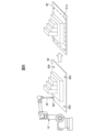
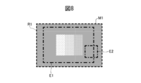
- FIG. 2 is a diagram for explaining an imaging range and a search range.
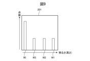
- FIG. 9 is a diagram illustrating a histogram for the first search range illustrated in FIG. 8 .
- FIG. 9 is a diagram illustrating a histogram for the second search range illustrated in FIG. 8 .
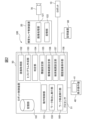
- 10 is a flowchart showing a general representation of an object presence/absence determination function executed by a robot control device.
- 10 is a flowchart showing a specific operation of an object presence/absence determination process executed by the robot control device.
- 13 is a flowchart showing a case where an object presence/absence determination process is applied to a workpiece transfer process.
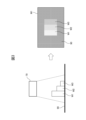
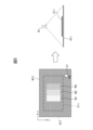
- the search range setting unit 157 accepts an input that specifies the search range E11 as numerical information based on the coordinates on the distance image M11, as shown, for example, on the left side of FIG. 4.
- the search range setting unit 157 may be configured to accept a search range specification in a form that simultaneously applies the above specification methods (a1) and (a2). In this case, the search range setting unit 157 accepts a specification in a procedure in which, for example, the operator sets the search range on the GUI and then precisely sets the search range using numerical information.
- the determination unit 154 determines whether or not an object has been placed within a range corresponding to the search range E11 in real space based on the distance image. Because the search range is set as a fixed range in real space, it is possible to determine a fixed range in real space even if the position or orientation of the visual sensor 70 changes and the imaging range moves. This function (F1) is effective in cases where the work location of the robot is fixed at a predetermined location.
- the search range setting unit 157 receives an input for specifying the search range as a range in the real work space.
- the search range setting unit 157 may specify the search range as a range in the real space using the following method: (b1) A method of specifying a search range in real space by performing a touch-up operation on the robot; (b2) A method of specifying a search range as position information in real space from an input source such as a robot program or user settings.
- the above function (F4) will be explained with reference to FIG. 7.
- an example will be given in which the above-mentioned designation method (b1) is used.
- the operator touches up the robot to designate multiple points in real space (see the left side of FIG. 7). This allows the three-dimensional coordinate values representing the positions of the four corners of the search range to be obtained.
- the search range setting unit 157 sets the search range E12 in real space specified by the touch-up operation as a search range (shown with the same reference number E12 on the right side of Figure 7) that corresponds to the image capture range R11 of the visual sensor 70. Therefore, in the case of this function, the search range E12 is set as a position based on the image capture range R11, and even if the position or orientation of the visual sensor changes and the image capture range R11 moves, the search range moves accordingly. In other words, the position of the search range on the captured image can always be fixed.
- the determination unit 154 determines whether an object is placed within a search range E12 set for the distance image of the imaging range R11. Because the search range is set in association with the imaging range, the range of the determination target on the captured image can always be fixed.
- the search range can be specified as a range on an image, or as a range in real space. Therefore, the operator can specify an appropriate search range depending on the situation and various conditions including the work content and the environmental conditions of the work space.
- possible input methods for specifying the search range include a method of specification from the robot program, a method of specification by user input via a UI, and a method of specification by touching up the robot. In this way, this embodiment can provide a high degree of freedom in the method of specifying the search range.
- the determination unit 154 determines whether or not an object has been placed on the surface to be inspected based on the distance image and the search range set as described above as the object of determination.
- the determination unit 154 determines whether or not an object has been placed in the search range.
- the histogram creation unit 153 determines whether or not an object has been placed on the surface to be inspected based on a frequency distribution (histogram) created from the distance image. Methods other than the frequency distribution (histogram) illustrated here may also be used as a method for determining whether or not an object has been placed.
- the histogram creation unit 153 creates a histogram with distance (brightness) as a variable for an image whose brightness changes according to distance, such as the distance image M1.
- the histogram creation unit 153 may be configured to search for a point cloud within a search range set by the function of the search range setting unit 157 on the distance image to create a histogram.
- An example will be described using the distance image M1 acquired as shown in FIG. 3. As shown in FIG. 8, it is assumed that a search range E1 is specified on the distance image M1.
- a histogram 201 created by the histogram creation unit 153 is shown in FIG. 9. In the histogram 201 in FIG.
- the brightness of the floor surface 90 may be set by user input.
- search range E1 By specifying a wide search range within the imaging range R1, such as search range E1, a histogram can be obtained for a wide range, making it possible to confirm the presence or absence of an object within the wide range.
- a relatively narrow search range such as search range E2 is useful when it is desired to quickly determine the presence or absence of an object in a limited area.
- limiting the search range to a relatively narrow range makes it possible to reduce the possibility of the histogram containing outliers.
- the first embodiment is an example of operation when object presence/absence determination processing is applied to the workpiece transfer operation by the workpiece transfer execution unit 160.
- FIG. 13 is a flowchart when object presence/absence determination processing is applied to the workpiece transfer processing. This processing is executed under the control of the processor 51 of the robot control device 50.
- the work transfer execution unit 160 uses the robot 10 to take out a work from a supply device such as a belt conveyor (step S11).
- a supply device such as a belt conveyor
- the work transfer execution unit 160 executes an object presence/absence determination process to confirm that no object is placed at the destination (step S12). Note that in this example, the operation of the robot 10 to place the work at the destination is taught on the premise that there are no objects (obstacles) at the destination.
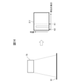
- Figure 14 shows the state in which the visual sensor 70 captures a distance image when nothing is placed on the destination placement surface 91, and shows a histogram 211 of the distance image acquired at that time.
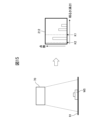
- Figure 15 shows the state in which the visual sensor 70 captures a distance image when a workpiece W5 is placed on the placement surface 91, and shows a histogram 212 acquired at that time.
- the threshold setting unit 155 provides a function for setting a threshold for determining whether or not there is a frequency of a height (brightness) other than the height (brightness) of the placement surface 91 in the distance image.
- the threshold may be set as an upper limit value K1 and a lower limit value K2 for defining a range including the reference height (brightness) based on the height (brightness) of the placement surface 91, as shown in FIG. 14, for example.
- the determination unit 154 can determine that an object is placed on the placement surface 91 when the presence of a point cloud of brightness outside the range defined by the upper limit value K1 and the lower limit value K2 is recognized.
- the thresholds may be set by a user or may be automatically set by the threshold setting unit 155.
- the threshold setting unit 155 performs automatic setting of the thresholds (upper limit K1 and lower limit K2) according to the following procedure: r1) Identifying the brightness having a frequency in the pre-stored histogram 211 as the brightness of the placement surface 91; r2) The brightness obtained by adding a predetermined margin to the brightness of the placement surface 91 is set as an upper limit value K1, and the brightness obtained by subtracting the predetermined margin from the brightness of the placement surface 91 is set as a lower limit value K2. It may be carried out by.
- GUI screen 350 When the threshold setting unit 155 accepts user settings of the thresholds (upper limit K1, lower limit K2), a graphical user interface screen (GUI screen 350) as shown in FIG. 16 may be provided on the display unit 41 of the teaching operation panel 40.
- the GUI screen 350 shown in FIG. 16 is configured to display a histogram created by the histogram creation unit 153 based on a distance image captured when there is no object on the surface to be inspected, and to accept the setting of the threshold on the screen.
- the GUI screen 350 shown in FIG. 16 is configured so that the upper limit K1 and lower limit K2 of the threshold can be input in the numerical input fields 351 and 352, sandwiching the brightness N1 of the surface to be inspected.
- step S12 During inspection (i.e., in the process of determining whether or not an object is present in step S12), assume that a workpiece W5 remains on the placement surface 91 as shown in FIG. 15. In this case, a histogram 212 is generated as shown on the right side of FIG. 15. The determination unit 154 then identifies the presence of a point group whose brightness exceeds the upper threshold value K1 (i.e., the presence of a workpiece W5). In this case, it is determined in step S13 that an object has been placed on the surface to be inspected (S13: YES), the task of placing the workpiece is interrupted, and the process proceeds to step 15.
- K1 i.e., the presence of a workpiece W5
- step S13 determines whether object is placed on the surface to be inspected (S13: NO)
- the work transfer execution unit 160 executes the task of placing a work on the placement surface 91 (step S14). Then, the work transfer execution unit 160 may continue the task of picking up and transferring the next work.
- the history image saved in step S15 can be used to understand the situation in which the workpiece W5 remains on the placement surface 91 and to analyze the cause. This also makes it possible to take necessary measures.
- FIG. 17 is a flowchart when the object presence/absence determination process is applied to the removal of bulk workpieces. This process is executed under the control of the processor 51 of the robot control device 50.
- the operation is to remove workpieces W6 (only some of the workpieces are marked with reference numbers) that are piled up in a container 95 on the floor surface 90 as shown in FIGS. 18 and 19.
- the work removal execution unit 159 executes the process of removing the bulk workpieces according to the work removal program stored in the memory unit 161 (step S21). The work removal execution unit 159 then determines whether or not the removal of the bulk workpieces has been completed based on a predetermined completion determination condition (step S22).
- the predetermined completion determination condition is, for example, that workpiece W6 is not detected as a detection result of the detection process of the workpiece W6 executed based on a two-dimensional image captured by the visual sensor 70 of the inside of the container 95. If it is determined that the removal of the workpieces has not been completed (S22: NO), the workpiece removal process continues.
- step S23 it is determined whether or not the workpiece W6 remains in the container 95.
- Fig. 18 shows a situation in which the visual sensor 70 captures a distance image when many workpieces W6 are present in the container 95, and a histogram 221 of the distance image acquired at that time.
- Fig. 19 shows a situation in which the visual sensor 70 captures a distance image when there is nothing in the container 95, and a histogram 222 of the distance image acquired at that time.
- Fig. 20 shows a situation in which the visual sensor 70 captures a distance image when one workpiece W6 remains in the container 95, and a histogram 223 of the distance image acquired at that time.
- the histogram 222 captured when there is nothing in the container 95 as shown in FIG. 19 is stored in advance in the storage unit 161.
- the threshold setting unit 155 identifies the height (brightness) of the bottom surface 95a of the container 95 based on this histogram 222, and determines the upper limit K1 and lower limit K2 of the threshold based on this brightness.
- the identification of the brightness of the bottom surface 95a and the setting of the threshold can be performed according to the above-mentioned steps (r1) and (r2).
- steps (r1) and (r2) can be performed according to the above-mentioned steps (r1) and (r2).
- the situation inside the container 95 when the object presence/absence determination process is executed is assumed to be one in which a workpiece W6 remains, as shown in FIG. 20.
- the determination unit 154 determines the presence or absence of an object on the surface to be inspected using the histogram 223 shown in FIG. 20. In the histogram 223, a distribution of points is observed in an area of brightness that exceeds the range determined by the upper and lower threshold values K1 and K2. Therefore, in this case, the determination unit 154 determines that an object is present on the bottom surface 95a, which is the surface to be inspected (S24: YES).
- the history image storage unit 158 stores a two-dimensional image of the state in which the workpiece W6 remains on the bottom surface 95a, captured by the two-dimensional camera function of the visual sensor 70, as a history image together with other history information in the storage device 80 (step S25). Then, the workpiece removal execution unit 159 ends this process.
- the workpiece removal process according to this embodiment can reliably detect the problem of the robot control device determining that workpiece removal is complete when a workpiece remains in the container.
- the imaging range or search range may be adjusted in advance so that the side of the container 95 is not measured.
- the histogram will show the frequency of only the height of the bottom surface 95a of the container 95 and the workpiece W6 (if workpiece W6 is present), making it possible to more accurately determine the presence or absence of an object.
- the functional arrangement in the functional block diagram shown in FIG. 2 is an example, and various modified examples of the functional arrangement may be configured.
- a configuration example may be one in which some of the functional blocks arranged in the robot control device 50 (e.g., the threshold setting unit 155, the image capture range setting unit 156, and the search range setting unit 157) are arranged on the teaching operation panel 40 side.
- the functions of the teaching pendant 40 may be included in the functions of the robot control device 50 and defined as a robot control device.
- the determination unit 154 may use distance data for each point in the distance image to determine whether or not an object is placed within a specified search range. In this case, for example, when the presence of an object having a specific height based on the height of a reference surface within the search range is recognized, it may be determined that an object is placed within the search range (on the reference surface). Note that when the determination unit is configured in this way, the functions related to the determination using the histogram (histogram creation unit 153 and threshold setting unit 155) can be omitted.
- the above-mentioned object presence/absence determination process (Figs. 11 and 12) can be executed on various information processing devices.
- the programs for executing various processes such as the object presence/absence determination process (FIGS. 11 and 12), the workpiece transfer process (FIG. 13), and the workpiece removal process (FIG. 17) in the above-described embodiment can be recorded on various computer-readable recording media (for example, semiconductor memory such as ROM, EEPROM, and flash memory, magnetic recording media, and optical disks such as CD-ROM and DVD-ROM).
- semiconductor memory such as ROM, EEPROM, and flash memory
- magnetic recording media for example, magnetic recording media, and optical disks such as CD-ROM and DVD-ROM.
- a control device (50) comprising an image acquisition unit (152) that acquires a distance image captured by a visual sensor (70), and a judgment unit (154) that judges whether an object is placed within a range specified by predetermined input information based on the distance image.
- (Appendix 4) The control device (50) according to claim 2, wherein the predetermined input information is information that specifies the search range as a range in real space.
- (Appendix 5) The control device (50) according to any one of appendices 1 to 4, wherein the predetermined input information is described in a robot program.
- (Appendix 6) The control device (50) according to any one of appendices 1 to 4, wherein the predetermined input information is information input via a user interface.
- (Appendix 7) The control device (50) according to any one of appendices 2 to 4, wherein the search range setting unit (157) sets the search range as a range defined in real space.
- (Appendix 13) The control device (50) according to any one of appendices 1 to 12, wherein the determination unit (154) determines whether or not an object is placed on the inspection target surface within the specified range.
- (Appendix 14) The control device (50) described in Appendix 13, wherein the judgment unit (154) judges whether or not an object is placed on the inspection surface based on a frequency distribution of distance information for each point in the acquired distance image.
- the control device (50) described in Appendix 14 further includes a threshold setting unit (155) for setting a threshold for distinguishing between distance information of the inspection surface in the frequency distribution and distance information of other objects on the inspection surface, and the judgment unit (154) judges whether or not an object is placed on the inspection surface using the threshold.
- (Appendix 16) The control device (50) described in Appendix 15, wherein the threshold setting unit (155) sets the threshold based on a frequency distribution of distance information for each point of a distance image obtained when no object is placed on the inspection surface.
- (Appendix 17) The control device (50) described in Appendix 15, wherein the threshold setting unit (155) is configured to provide a user interface that accepts setting of the threshold by a user operation.
- (Appendix 18) The control device (50) of claim 17, wherein the user interface is configured as a graphical user interface including an image representing a frequency distribution of the distance image.
- (Appendix 19) The control device (50) described in Appendix 15, wherein the threshold setting unit (155) sets the threshold according to threshold information described in a robot program.
- Appendix 20 A control device (50) described in any one of Appendices 14 to 19, further comprising a histogram creation unit (153) that generates an image representing the frequency distribution based on distance information of each point in the acquired distance image and displays it on a display screen.
- Appendix 21 The control device (50) according to claim 20, wherein the histogram creation unit (153) is configured to generate an image representing the frequency distribution in a specified range in the distance image.
- Appendix 23 The control device (50) described in any one of Appendices 14 to 21, further comprising a work removal execution unit (159) for executing a removal operation in which the robot (10) removes workpieces randomly stacked in a container, and the judgment unit (154) judges whether or not there is an object on the bottom surface of the container based on a distance image captured of the bottom surface of the container when the work removal execution unit (159) determines that the removal of the workpieces is complete based on predetermined completion judgment conditions.
- Appendix 24 The control device (50) according to claim 22 or 23, further comprising a historical image storage unit (158) that stores a historical image when the determination unit (154) determines that an object is present.
- (Appendix 25) A control device described in any one of Appendix 14 to 24, wherein the distance image is an image that represents the distance information of each point by brightness, and the frequency distribution represents the distribution of brightness of each point of the distance image.
- (Appendix 26) A robot system (100) comprising a robot (10), a visual sensor (70), and a control device (50) described in any one of Supplementary Notes 1 to 25, wherein the control device (50) controls the robot (10).
- (Appendix 27) A method executed on an information processing device, comprising: A distance image captured by a visual sensor (70) is acquired; The object presence/absence determining method determines, based on the distance image, whether or not an object is placed within a range specified by predetermined input information.
- the computer processor A procedure for acquiring a distance image captured by a visual sensor (70); a step of determining whether or not an object is placed within a range specified by predetermined input information based on the distance image; A program for executing.
Landscapes
- Engineering & Computer Science (AREA)
- Robotics (AREA)
- Mechanical Engineering (AREA)
- Automation & Control Theory (AREA)
- Evolutionary Computation (AREA)
- Artificial Intelligence (AREA)
- Physics & Mathematics (AREA)
- Fuzzy Systems (AREA)
- Mathematical Physics (AREA)
- Software Systems (AREA)
- Multimedia (AREA)
- Human Computer Interaction (AREA)
- Manipulator (AREA)
- Image Analysis (AREA)
Abstract
Description
(F1)撮像された画像上で指定された検索範囲を、実作業空間上に定めた範囲として設定する機能。
(F2)撮像された画像上で指定された検索範囲を、視覚センサの撮像範囲に対応付けて設定する機能。
(F3)実空間上に検索範囲を設定する機能。
(F4)実空間上で指定された検索範囲を、視覚センサの撮像範囲に対応付けて設定する機能。
(a1)検索範囲を画像上の座標に準拠した数値情報として指定する手法と、
(a2)GUI(グラフィカルユーザインタフェース)上で検索範囲を指定する入力手法と、を受け付け可能に構成される。
(b1)ロボットをタッチアップ操作して実空間上で検索範囲を指定する手法と、
(b2)ロボットプログラム或いはユーザ設定等の入力源から実空間上の位置情報として検索範囲を指定する手法と、を受け付け可能に構成される。
r1)予め保存されているヒストグラム211において度数を有する明るさを、載置面91の明るさであると特定し、
r2)載置面91の明るさに所定のマージンをプラスした明るさを上限値K1とし、載置面91の明るさから所定のマージンを減じた明るさを下限値K2と設定する、
により行っても良い。
(d1)検査時の距離画像中で最も度数が多い、或いは、
(d2)検査時の距離画像中で最も度数が多く且つ最も暗い
という条件を満たす点群について検査対象面であると判定するアルゴリズムを採用しても良い。アルゴリズム(d1)は、検査対象面に基本的にものがあまり置かれていない場合が多いと想定されるような状況において有効である。アルゴリズム(d2)は、検査対象面に基本的にものがあまり置かれていない場合が多く、且つ、検査対処面が床面等の撮像範囲内(或いは検索範囲内)で最も低い位置にある場合に有効である。
(付記1)
視覚センサ(70)により撮像された距離画像を取得する画像取得部(152)と、前記距離画像に基づき、所定の入力情報により指定された範囲内に物が置かれているか否かを判定する判定部(154)と、を備える制御装置(50)。
(付記2)
前記所定の入力情報により指定された前記範囲を検索範囲として設定する検索範囲設定部(157)を更に備える、付記1に記載の制御装置(50)。
(付記3)
前記所定の入力情報は、前記検索範囲を画像上の範囲として指定する情報である、付記2に記載の制御装置(50)。
(付記4)
前記所定の入力情報は、前記検索範囲を実空間上の範囲として指定する情報である、付記2に記載の制御装置(50)。
(付記5)
前記所定の入力情報は、ロボットプログラムに記述されている、付記1から4のいずれか一項に記載の制御装置(50)。
(付記6)
前記所定の入力情報は、ユーザインタフェースを介して入力された情報である付記1から4のいずれか一項に記載の制御装置(50)。
(付記7)
前記検索範囲設定部(157)は、実空間上に定めた範囲として前記検索範囲を設定する、付記2から4のいずれか一項に記載の制御装置(50)。
(付記8)
前記検索範囲設定部(157)は、前記視覚センサ(70)の撮像範囲に対応付けた範囲として前記検索範囲を設定する、付記2から4のいずれか一項に記載の制御装置(50)。
(付記9)
前記画像上の範囲は、当該画像上の座標に準拠する数値情報として表されている、付記3に記載の制御装置(50)。
(付記10)
前記検索範囲設定部(157)は、前記画像上の範囲をグラフィカルな操作により指定するためのグラフィカルユーザインタフェースを提供する、付記3に記載の制御装置(50)。
(付記11)
前記検索範囲設定部(157)は、ロボット(10)に実空間上の複数の点をタッチアップさせる動作を実行させることにより得られる前記複数の点の3次元座標を、前記検索範囲を実空間上の範囲として指定する情報として取得する、付記4に記載の制御装置(50)。
(付記12)
前記所定の入力情報により指定された範囲を、前記視覚センサ(70)が撮像する前記撮像範囲として設定するための撮像範囲設定部(156)を更に備え、前記撮像範囲設定部(156)は、前記視覚センサ(70)に対し、設定された前記撮像範囲で前記視覚センサが撮像を行うよう指令する信号を送出する、付記1に記載の制御装置(50)。
(付記13)
前記判定部(154)は、指定された前記範囲内において検査対象面に物が置かれているか否かを判定する、付記1から12のいずれか一項に記載の制御装置(50)。
(付記14)
前記判定部(154)は、取得された前記距離画像中の各点の距離情報に関する度数分布に基づいて、前記検査対象面に物が置かれているか否かを判定する、付記13に記載の制御装置(50)。
(付記15)
前記度数分布における前記検査対象面の距離情報と、前記検査対象面における他の物体の距離情報とを識別するための閾値を設定するための閾値設定部(155)を更に備え、前記判定部(154)は前記閾値を用いて前記検査対象面に物が置かれているか否かを判定する、付記14に記載の制御装置(50)。
(付記16)
前記閾値設定部(155)は、前記検査対象面に物が置かれていない状況において得られた距離画像の各点の距離情報に関する度数分布に基づいて前記閾値を設定する、付記15に記載の制御装置(50)。
(付記17)
前記閾値設定部(155)は、ユーザ操作による前記閾値の設定を受け付けるユーザインタフェースを提供するように構成されている、付記15に記載の制御装置(50)。
(付記18)
前記ユーザインタフェースは、前記距離画像の度数分布を表す画像を含むグラフィカルユーザインタフェースとして構成されている、付記17に記載の制御装置(50)。
(付記19)
前記閾値設定部(155)は、ロボットプログラムに記述された閾値情報にしたがい前記閾値を設定する、付記15に記載の制御装置(50)。
(付記20)
取得された前記距離画像中の各点の距離情報に基づき前記度数分布を表す画像を生成し表示画面に表示するヒストグラム作成部(153)を更に備える、付記14から19のいずれか一項に記載の制御装置(50)。
(付記21)
前記ヒストグラム作成部(153)は、前記距離画像中の指定された範囲で前記度数分布を表す画像を生成するように構成されている、付記20に記載の制御装置(50)。
(付記22)
ロボット(10)により供給装置からワークを取り出し所定の載置面に置くワーク移送作業を実行するためのワーク移送実行部(160)を更に備え、
前記判定部(154)は、前記ワーク移送実行部(160)が前記ワークを前記載置面に置く前に、前記載置面を撮像した距離画像に基づき、前記載置面に物があるか否かを判定する、付記14から21のいずれか一項に記載の制御装置(50)。
(付記23)
ロボット(10)により容器内にバラ積みされたワークを取り出す取出し作業を実行するためのワーク取出し実行部(159)を更に備え、前記判定部(154)は、前記ワーク取出し実行部(159)が所定の完了判定条件に基づきワークの取出しの完了判定を下した際に、前記容器の底面を撮像した距離画像に基づいて、前記容器の底面に物があるか否かを判定する、付記14から21のいずれか一項に記載の制御装置(50)。
(付記24)
前記判定部(154)により物があると判定された場合に履歴画像を保存する履歴画像保存部(158)を更に備える、付記22又は23に記載の制御装置(50)。
(付記25)
前記距離画像は、各点の前記距離情報を明るさにより表す画像であり、前記度数分布は、前記距離画像の各点の明るさの分布を表す、付記14から24のいずれか一項に記載の制御装置。
(付記26)
ロボット(10)と、視覚センサ(70)と、付記1から25のいずれか一項に記載の制御装置(50)と、を具備し、前記制御装置(50)は前記ロボット(10)を制御する、ロボットシステム(100)。
(付記27)
情報処理装置上で実行される方法であって、
視覚センサ(70)により撮像された距離画像を取得し、
前記距離画像に基づき、所定の入力情報により指定された範囲内に物が置かれているか否かを判定する、物体有無判定方法。
(付記28)
コンピュータのプロセッサに、
視覚センサ(70)により撮像された距離画像を取得する手順と、
前記距離画像に基づき、所定の入力情報により指定された範囲内に物が置かれているか否かを判定する手順と、
を実行させるためのプログラム。
20 視覚センサ制御装置
33 ハンド
40 教示操作盤
50 ロボット制御装置
51 プロセッサ
70 視覚センサ
80 記憶装置
90 床面
91 載置面
95 コンテナ
95a 底面
100 ロボットシステム
121 画像処理部
122 記憶部
151 動作制御部
152 画像取得部
153 ヒストグラム作成部
154 判定部
155 閾値設定部
156 撮像範囲設定部
157 検索範囲設定部
158 履歴画像保存部
159 ワーク取出し実行部
160 ワーク移送実行部
161 記憶部
350 GUI画面
Claims (28)
- 視覚センサにより撮像された距離画像を取得する画像取得部と、
前記距離画像に基づき、所定の入力情報により指定された範囲内に物が置かれているか否かを判定する判定部と、
を備える制御装置。 - 前記所定の入力情報により指定された前記範囲を検索範囲として設定する検索範囲設定部を更に備える、請求項1に記載の制御装置。
- 前記所定の入力情報は、前記検索範囲を画像上の範囲として指定する情報である、請求項2に記載の制御装置。
- 前記所定の入力情報は、前記検索範囲を実空間上の範囲として指定する情報である、請求項2に記載の制御装置。
- 前記所定の入力情報は、ロボットプログラムに記述されている、請求項1から4のいずれか一項に記載の制御装置。
- 前記所定の入力情報は、ユーザインタフェースを介して入力された情報である請求項1から4のいずれか一項に記載の制御装置。
- 前記検索範囲設定部は、実空間上に定めた範囲として前記検索範囲を設定する、請求項2から4のいずれか一項に記載の制御装置。
- 前記検索範囲設定部は、前記視覚センサの撮像範囲に対応付けた範囲として前記検索範囲を設定する、請求項2から4のいずれか一項に記載の制御装置。
- 前記画像上の範囲は、当該画像上の座標に準拠する数値情報として表されている、請求項3に記載の制御装置。
- 前記検索範囲設定部は、前記画像上の範囲をグラフィカルな操作により指定するためのグラフィカルユーザインタフェースを提供する、請求項3に記載の制御装置。
- 前記検索範囲設定部は、ロボットに実空間上の複数の点をタッチアップさせる動作を実行させることにより得られる前記複数の点の3次元座標を、前記検索範囲を実空間上の範囲として指定する情報として取得する、請求項4に記載の制御装置。
- 前記所定の入力情報により指定された範囲を、前記視覚センサが撮像する撮像範囲として設定するための撮像範囲設定部を更に備え、
前記撮像範囲設定部は、前記視覚センサに対し、設定された前記撮像範囲で前記視覚センサが撮像を行うよう指令する信号を送出する、請求項1に記載の制御装置。 - 前記判定部は、指定された前記範囲内において検査対象面に物が置かれているか否かを判定する、請求項1から12のいずれか一項に記載の制御装置。
- 前記判定部は、取得された前記距離画像中の各点の距離情報に関する度数分布に基づいて、前記検査対象面に物が置かれているか否かを判定する、請求項13に記載の制御装置。
- 前記度数分布における前記検査対象面の距離情報と、前記検査対象面における他の物体の距離情報とを識別するための閾値を設定するための閾値設定部を更に備え、
前記判定部は前記閾値を用いて前記検査対象面に物が置かれているか否かを判定する、請求項14に記載の制御装置。 - 前記閾値設定部は、前記検査対象面に物が置かれていない状況において得られた距離画像の各点の距離情報に関する度数分布に基づいて前記閾値を設定する、請求項15に記載の制御装置。
- 前記閾値設定部は、ユーザ操作による前記閾値の設定を受け付けるユーザインタフェースを提供するように構成されている、請求項15に記載の制御装置。
- 前記ユーザインタフェースは、前記距離画像の度数分布を表す画像を含むグラフィカルユーザインタフェースとして構成されている、請求項17に記載の制御装置。
- 前記閾値設定部は、ロボットプログラムに記述された閾値情報にしたがい前記閾値を設定する、請求項15に記載の制御装置。
- 取得された前記距離画像中の各点の距離情報に基づき前記度数分布を表す画像を生成し表示画面に表示するヒストグラム作成部を更に備える、請求項14から19のいずれか一項に記載の制御装置。
- 前記ヒストグラム作成部は、前記距離画像中の指定された範囲で前記度数分布を表す画像を生成するように構成されている、請求項20に記載の制御装置。
- ロボットにより供給装置からワークを取り出し所定の載置面に置くワーク移送作業を実行するためのワーク移送実行部を更に備え、
前記判定部は、前記ワーク移送実行部が前記ワークを前記載置面に置く前に、前記載置面を撮像した距離画像に基づき、前記載置面に物があるか否かを判定する、請求項14から21のいずれか一項に記載の制御装置。 - ロボットにより容器内にバラ積みされたワークを取り出す取出し作業を実行するためのワーク取出し実行部を更に備え、
前記判定部は、前記ワーク取出し実行部が所定の完了判定条件に基づきワークの取出しの完了判定を下した際に、前記容器の底面を撮像した距離画像に基づいて、前記容器の底面に物があるか否かを判定する、請求項14から21のいずれか一項に記載の制御装置。 - 前記判定部により物があると判定された場合に履歴画像を保存する履歴画像保存部を更に備える、請求項22又は23に記載の制御装置。
- 前記距離画像は、各点の前記距離情報を明るさにより表す画像であり、
前記度数分布は、前記距離画像の各点の明るさの分布を表す、
請求項14から24のいずれか一項に記載の制御装置。 - ロボットと、
視覚センサと、
請求項1から25のいずれか一項に記載の制御装置と、を具備し、
前記制御装置は前記ロボットを制御する、ロボットシステム。 - 情報処理装置上で実行される方法であって、
視覚センサにより撮像された距離画像を取得し、
前記距離画像に基づき、所定の入力情報により指定された範囲内に物が置かれているか否かを判定する、物体有無判定方法。 - コンピュータのプロセッサに、
視覚センサにより撮像された距離画像を取得する手順と、
前記距離画像に基づき、所定の入力情報により指定された範囲内に物が置かれているか否かを判定する手順と、
を実行させるためのプログラム。
Priority Applications (6)
| Application Number | Priority Date | Filing Date | Title |
|---|---|---|---|
| CN202280102671.1A CN120379802A (zh) | 2022-12-26 | 2022-12-26 | 控制装置、机器人系统、有无物体判定方法以及程序 |
| JP2024566948A JPWO2024142159A1 (ja) | 2022-12-26 | 2022-12-26 | |
| DE112022007881.2T DE112022007881T5 (de) | 2022-12-26 | 2022-12-26 | Steuergerät, robotersystem, verfahren zur bestimmung der anwesenheit/abwesenheit von objekten und programm |
| PCT/JP2022/047928 WO2024142159A1 (ja) | 2022-12-26 | 2022-12-26 | 制御装置、ロボットシステム、物体有無判定方法、及びプログラム |
| TW112145770A TW202426226A (zh) | 2022-12-26 | 2023-11-27 | 控制裝置、機器人系統、物體有無判定方法、及程式 |
| US19/194,591 US20250256404A1 (en) | 2022-12-26 | 2025-04-30 | Control device, robot system, object presence/absence determination method, and program |
Applications Claiming Priority (1)
| Application Number | Priority Date | Filing Date | Title |
|---|---|---|---|
| PCT/JP2022/047928 WO2024142159A1 (ja) | 2022-12-26 | 2022-12-26 | 制御装置、ロボットシステム、物体有無判定方法、及びプログラム |
Related Child Applications (1)
| Application Number | Title | Priority Date | Filing Date |
|---|---|---|---|
| US19/194,591 Continuation US20250256404A1 (en) | 2022-12-26 | 2025-04-30 | Control device, robot system, object presence/absence determination method, and program |
Publications (1)
| Publication Number | Publication Date |
|---|---|
| WO2024142159A1 true WO2024142159A1 (ja) | 2024-07-04 |
Family
ID=91716930
Family Applications (1)
| Application Number | Title | Priority Date | Filing Date |
|---|---|---|---|
| PCT/JP2022/047928 Ceased WO2024142159A1 (ja) | 2022-12-26 | 2022-12-26 | 制御装置、ロボットシステム、物体有無判定方法、及びプログラム |
Country Status (6)
| Country | Link |
|---|---|
| US (1) | US20250256404A1 (ja) |
| JP (1) | JPWO2024142159A1 (ja) |
| CN (1) | CN120379802A (ja) |
| DE (1) | DE112022007881T5 (ja) |
| TW (1) | TW202426226A (ja) |
| WO (1) | WO2024142159A1 (ja) |
Citations (3)
| Publication number | Priority date | Publication date | Assignee | Title |
|---|---|---|---|---|
| JP3174872U (ja) * | 2012-01-30 | 2012-04-12 | 計測技研株式会社 | 建ち精度算出装置 |
| JP2020017111A (ja) * | 2018-07-26 | 2020-01-30 | ファナック株式会社 | ワーク計測装置、ワーク計測方法及びプログラム |
| JP2021073099A (ja) * | 2018-03-09 | 2021-05-13 | ソニーグループ株式会社 | 制御システム及び制御システムにおける方法 |
-
2022
- 2022-12-26 CN CN202280102671.1A patent/CN120379802A/zh active Pending
- 2022-12-26 JP JP2024566948A patent/JPWO2024142159A1/ja active Pending
- 2022-12-26 DE DE112022007881.2T patent/DE112022007881T5/de active Pending
- 2022-12-26 WO PCT/JP2022/047928 patent/WO2024142159A1/ja not_active Ceased
-
2023
- 2023-11-27 TW TW112145770A patent/TW202426226A/zh unknown
-
2025
- 2025-04-30 US US19/194,591 patent/US20250256404A1/en active Pending
Patent Citations (3)
| Publication number | Priority date | Publication date | Assignee | Title |
|---|---|---|---|---|
| JP3174872U (ja) * | 2012-01-30 | 2012-04-12 | 計測技研株式会社 | 建ち精度算出装置 |
| JP2021073099A (ja) * | 2018-03-09 | 2021-05-13 | ソニーグループ株式会社 | 制御システム及び制御システムにおける方法 |
| JP2020017111A (ja) * | 2018-07-26 | 2020-01-30 | ファナック株式会社 | ワーク計測装置、ワーク計測方法及びプログラム |
Also Published As
| Publication number | Publication date |
|---|---|
| TW202426226A (zh) | 2024-07-01 |
| DE112022007881T5 (de) | 2025-09-11 |
| CN120379802A (zh) | 2025-07-25 |
| US20250256404A1 (en) | 2025-08-14 |
| JPWO2024142159A1 (ja) | 2024-07-04 |
Similar Documents
| Publication | Publication Date | Title |
|---|---|---|
| US12314901B2 (en) | Robotic system with automated object detection mechanism and methods of operating the same | |
| JP6744709B2 (ja) | 情報処理装置、情報処理方法 | |
| CN104842361B (zh) | 具有3d箱体定位功能的机器人系统 | |
| CN108235696B (zh) | 机器人控制方法和设备 | |
| JP7337495B2 (ja) | 画像処理装置およびその制御方法、プログラム | |
| US11839980B2 (en) | Image processing apparatus monitoring target, control method therefor, and storage medium storing control program therefor | |
| US20210197391A1 (en) | Robot control device, robot control method, and robot control non-transitory computer readable medium | |
| US20160167232A1 (en) | Placement determining method, placing method, placement determination system, and robot | |
| CN113302027B (zh) | 作业坐标生成装置 | |
| JP2012230041A (ja) | 位置検出方法、位置検出装置、ロボットシステム | |
| JP2022541120A (ja) | 高度なスキャニング技法を用いるロボットビンピッキングのためのシステム及び方法 | |
| US12296486B2 (en) | Program editing device | |
| WO2024142159A1 (ja) | 制御装置、ロボットシステム、物体有無判定方法、及びプログラム | |
| CN116175542A (zh) | 抓取控制方法、装置、电子设备和存储介质 | |
| CN116188559A (zh) | 图像数据处理方法、装置、电子设备和存储介质 | |
| JP2021102253A (ja) | 画像処理装置、ロボットシステム、及び画像処理方法 | |
| WO2024184976A1 (ja) | 画像処理装置 | |
| WO2025250119A1 (en) | Vision-based bin profiling for robotic bin picking | |
| TWM565327U (zh) | Robot arm control device | |
| JP2025035343A (ja) | ピッキングシステム、ピッキングロボット、及びピッキング方法 | |
| CN116197887A (zh) | 图像数据处理方法、装置、电子设备和存储介质 | |
| TW202504735A (zh) | 設定應檢測工件之檢測範圍的裝置、機器人系統、方法、及電腦程式 | |
| CN121443423A (zh) | 用于使用触摸屏进行校准的方法和系统 |
Legal Events
| Date | Code | Title | Description |
|---|---|---|---|
| 121 | Ep: the epo has been informed by wipo that ep was designated in this application |
Ref document number: 22969953 Country of ref document: EP Kind code of ref document: A1 |
|
| WWE | Wipo information: entry into national phase |
Ref document number: 2024566948 Country of ref document: JP |
|
| WWE | Wipo information: entry into national phase |
Ref document number: 112022007881 Country of ref document: DE |
|
| WWE | Wipo information: entry into national phase |
Ref document number: 202280102671.1 Country of ref document: CN |
|
| WWP | Wipo information: published in national office |
Ref document number: 202280102671.1 Country of ref document: CN |
|
| WWP | Wipo information: published in national office |
Ref document number: 112022007881 Country of ref document: DE |
|
| 122 | Ep: pct application non-entry in european phase |
Ref document number: 22969953 Country of ref document: EP Kind code of ref document: A1 |