WO2024135748A1 - 継手装置 - Google Patents
継手装置 Download PDFInfo
- Publication number
- WO2024135748A1 WO2024135748A1 PCT/JP2023/045795 JP2023045795W WO2024135748A1 WO 2024135748 A1 WO2024135748 A1 WO 2024135748A1 JP 2023045795 W JP2023045795 W JP 2023045795W WO 2024135748 A1 WO2024135748 A1 WO 2024135748A1
- Authority
- WO
- WIPO (PCT)
- Prior art keywords
- rotation axis
- rotating body
- coupling device
- gear
- power transmission
- Prior art date
- Legal status (The legal status is an assumption and is not a legal conclusion. Google has not performed a legal analysis and makes no representation as to the accuracy of the status listed.)
- Ceased
Links
Images


Classifications
-
- F—MECHANICAL ENGINEERING; LIGHTING; HEATING; WEAPONS; BLASTING
- F16—ENGINEERING ELEMENTS AND UNITS; GENERAL MEASURES FOR PRODUCING AND MAINTAINING EFFECTIVE FUNCTIONING OF MACHINES OR INSTALLATIONS; THERMAL INSULATION IN GENERAL
- F16H—GEARING
- F16H37/00—Combinations of mechanical gearings, not provided for in groups F16H1/00 - F16H35/00
- F16H37/02—Combinations of mechanical gearings, not provided for in groups F16H1/00 - F16H35/00 comprising essentially only toothed or friction gearings
- F16H37/04—Combinations of toothed gearings only
-
- A—HUMAN NECESSITIES
- A61—MEDICAL OR VETERINARY SCIENCE; HYGIENE
- A61F—FILTERS IMPLANTABLE INTO BLOOD VESSELS; PROSTHESES; DEVICES PROVIDING PATENCY TO, OR PREVENTING COLLAPSING OF, TUBULAR STRUCTURES OF THE BODY, e.g. STENTS; ORTHOPAEDIC, NURSING OR CONTRACEPTIVE DEVICES; FOMENTATION; TREATMENT OR PROTECTION OF EYES OR EARS; BANDAGES, DRESSINGS OR ABSORBENT PADS; FIRST-AID KITS
- A61F2/00—Filters implantable into blood vessels; Prostheses, i.e. artificial substitutes or replacements for parts of the body; Appliances for connecting them with the body; Devices providing patency to, or preventing collapsing of, tubular structures of the body, e.g. stents
- A61F2/50—Prostheses not implantable in the body
- A61F2/60—Artificial legs or feet or parts thereof
- A61F2/64—Knee joints
-
- A—HUMAN NECESSITIES
- A61—MEDICAL OR VETERINARY SCIENCE; HYGIENE
- A61F—FILTERS IMPLANTABLE INTO BLOOD VESSELS; PROSTHESES; DEVICES PROVIDING PATENCY TO, OR PREVENTING COLLAPSING OF, TUBULAR STRUCTURES OF THE BODY, e.g. STENTS; ORTHOPAEDIC, NURSING OR CONTRACEPTIVE DEVICES; FOMENTATION; TREATMENT OR PROTECTION OF EYES OR EARS; BANDAGES, DRESSINGS OR ABSORBENT PADS; FIRST-AID KITS
- A61F2/00—Filters implantable into blood vessels; Prostheses, i.e. artificial substitutes or replacements for parts of the body; Appliances for connecting them with the body; Devices providing patency to, or preventing collapsing of, tubular structures of the body, e.g. stents
- A61F2/50—Prostheses not implantable in the body
- A61F2/60—Artificial legs or feet or parts thereof
- A61F2/66—Feet; Ankle joints
-
- A—HUMAN NECESSITIES
- A61—MEDICAL OR VETERINARY SCIENCE; HYGIENE
- A61F—FILTERS IMPLANTABLE INTO BLOOD VESSELS; PROSTHESES; DEVICES PROVIDING PATENCY TO, OR PREVENTING COLLAPSING OF, TUBULAR STRUCTURES OF THE BODY, e.g. STENTS; ORTHOPAEDIC, NURSING OR CONTRACEPTIVE DEVICES; FOMENTATION; TREATMENT OR PROTECTION OF EYES OR EARS; BANDAGES, DRESSINGS OR ABSORBENT PADS; FIRST-AID KITS
- A61F2/00—Filters implantable into blood vessels; Prostheses, i.e. artificial substitutes or replacements for parts of the body; Appliances for connecting them with the body; Devices providing patency to, or preventing collapsing of, tubular structures of the body, e.g. stents
- A61F2/50—Prostheses not implantable in the body
- A61F2/68—Operating or control means
- A61F2/70—Operating or control means electrical
-
- F—MECHANICAL ENGINEERING; LIGHTING; HEATING; WEAPONS; BLASTING
- F16—ENGINEERING ELEMENTS AND UNITS; GENERAL MEASURES FOR PRODUCING AND MAINTAINING EFFECTIVE FUNCTIONING OF MACHINES OR INSTALLATIONS; THERMAL INSULATION IN GENERAL
- F16H—GEARING
- F16H3/00—Toothed gearings for conveying rotary motion with variable gear ratio or for reversing rotary motion
- F16H3/02—Toothed gearings for conveying rotary motion with variable gear ratio or for reversing rotary motion without gears having orbital motion
- F16H3/08—Toothed gearings for conveying rotary motion with variable gear ratio or for reversing rotary motion without gears having orbital motion exclusively or essentially with continuously meshing gears, that can be disengaged from their shafts
- F16H3/083—Toothed gearings for conveying rotary motion with variable gear ratio or for reversing rotary motion without gears having orbital motion exclusively or essentially with continuously meshing gears, that can be disengaged from their shafts with radially acting and axially controlled clutching members, e.g. sliding keys
-
- A—HUMAN NECESSITIES
- A61—MEDICAL OR VETERINARY SCIENCE; HYGIENE
- A61F—FILTERS IMPLANTABLE INTO BLOOD VESSELS; PROSTHESES; DEVICES PROVIDING PATENCY TO, OR PREVENTING COLLAPSING OF, TUBULAR STRUCTURES OF THE BODY, e.g. STENTS; ORTHOPAEDIC, NURSING OR CONTRACEPTIVE DEVICES; FOMENTATION; TREATMENT OR PROTECTION OF EYES OR EARS; BANDAGES, DRESSINGS OR ABSORBENT PADS; FIRST-AID KITS
- A61F2/00—Filters implantable into blood vessels; Prostheses, i.e. artificial substitutes or replacements for parts of the body; Appliances for connecting them with the body; Devices providing patency to, or preventing collapsing of, tubular structures of the body, e.g. stents
- A61F2/50—Prostheses not implantable in the body
- A61F2/68—Operating or control means
- A61F2002/6836—Gears specially adapted therefor, e.g. reduction gears
-
- A—HUMAN NECESSITIES
- A61—MEDICAL OR VETERINARY SCIENCE; HYGIENE
- A61F—FILTERS IMPLANTABLE INTO BLOOD VESSELS; PROSTHESES; DEVICES PROVIDING PATENCY TO, OR PREVENTING COLLAPSING OF, TUBULAR STRUCTURES OF THE BODY, e.g. STENTS; ORTHOPAEDIC, NURSING OR CONTRACEPTIVE DEVICES; FOMENTATION; TREATMENT OR PROTECTION OF EYES OR EARS; BANDAGES, DRESSINGS OR ABSORBENT PADS; FIRST-AID KITS
- A61F2/00—Filters implantable into blood vessels; Prostheses, i.e. artificial substitutes or replacements for parts of the body; Appliances for connecting them with the body; Devices providing patency to, or preventing collapsing of, tubular structures of the body, e.g. stents
- A61F2/50—Prostheses not implantable in the body
- A61F2/68—Operating or control means
- A61F2002/6845—Clutches
-
- A—HUMAN NECESSITIES
- A61—MEDICAL OR VETERINARY SCIENCE; HYGIENE
- A61F—FILTERS IMPLANTABLE INTO BLOOD VESSELS; PROSTHESES; DEVICES PROVIDING PATENCY TO, OR PREVENTING COLLAPSING OF, TUBULAR STRUCTURES OF THE BODY, e.g. STENTS; ORTHOPAEDIC, NURSING OR CONTRACEPTIVE DEVICES; FOMENTATION; TREATMENT OR PROTECTION OF EYES OR EARS; BANDAGES, DRESSINGS OR ABSORBENT PADS; FIRST-AID KITS
- A61F2/00—Filters implantable into blood vessels; Prostheses, i.e. artificial substitutes or replacements for parts of the body; Appliances for connecting them with the body; Devices providing patency to, or preventing collapsing of, tubular structures of the body, e.g. stents
- A61F2/50—Prostheses not implantable in the body
- A61F2/68—Operating or control means
- A61F2/70—Operating or control means electrical
- A61F2002/701—Operating or control means electrical operated by electrically controlled means, e.g. solenoids or torque motors
-
- A—HUMAN NECESSITIES
- A61—MEDICAL OR VETERINARY SCIENCE; HYGIENE
- A61F—FILTERS IMPLANTABLE INTO BLOOD VESSELS; PROSTHESES; DEVICES PROVIDING PATENCY TO, OR PREVENTING COLLAPSING OF, TUBULAR STRUCTURES OF THE BODY, e.g. STENTS; ORTHOPAEDIC, NURSING OR CONTRACEPTIVE DEVICES; FOMENTATION; TREATMENT OR PROTECTION OF EYES OR EARS; BANDAGES, DRESSINGS OR ABSORBENT PADS; FIRST-AID KITS
- A61F2/00—Filters implantable into blood vessels; Prostheses, i.e. artificial substitutes or replacements for parts of the body; Appliances for connecting them with the body; Devices providing patency to, or preventing collapsing of, tubular structures of the body, e.g. stents
- A61F2/50—Prostheses not implantable in the body
- A61F2/76—Means for assembling, fitting or testing prostheses, e.g. for measuring or balancing, e.g. alignment means
- A61F2002/7615—Measuring means
- A61F2002/7625—Measuring means for measuring angular position
-
- F—MECHANICAL ENGINEERING; LIGHTING; HEATING; WEAPONS; BLASTING
- F16—ENGINEERING ELEMENTS AND UNITS; GENERAL MEASURES FOR PRODUCING AND MAINTAINING EFFECTIVE FUNCTIONING OF MACHINES OR INSTALLATIONS; THERMAL INSULATION IN GENERAL
- F16H—GEARING
- F16H1/00—Toothed gearings for conveying rotary motion
- F16H1/02—Toothed gearings for conveying rotary motion without gears having orbital motion
- F16H1/04—Toothed gearings for conveying rotary motion without gears having orbital motion involving only two intermeshing members
- F16H1/12—Toothed gearings for conveying rotary motion without gears having orbital motion involving only two intermeshing members with non-parallel axes
- F16H1/16—Toothed gearings for conveying rotary motion without gears having orbital motion involving only two intermeshing members with non-parallel axes comprising worm and worm-wheel
-
- F—MECHANICAL ENGINEERING; LIGHTING; HEATING; WEAPONS; BLASTING
- F16—ENGINEERING ELEMENTS AND UNITS; GENERAL MEASURES FOR PRODUCING AND MAINTAINING EFFECTIVE FUNCTIONING OF MACHINES OR INSTALLATIONS; THERMAL INSULATION IN GENERAL
- F16H—GEARING
- F16H1/00—Toothed gearings for conveying rotary motion
- F16H1/28—Toothed gearings for conveying rotary motion with gears having orbital motion
- F16H1/32—Toothed gearings for conveying rotary motion with gears having orbital motion in which the central axis of the gearing lies inside the periphery of an orbital gear
-
- F—MECHANICAL ENGINEERING; LIGHTING; HEATING; WEAPONS; BLASTING
- F16—ENGINEERING ELEMENTS AND UNITS; GENERAL MEASURES FOR PRODUCING AND MAINTAINING EFFECTIVE FUNCTIONING OF MACHINES OR INSTALLATIONS; THERMAL INSULATION IN GENERAL
- F16H—GEARING
- F16H63/00—Control outputs from the control unit to change-speed- or reversing-gearings for conveying rotary motion or to other devices than the final output mechanism
- F16H63/02—Final output mechanisms therefor; Actuating means for the final output mechanisms
- F16H63/30—Constructional features of the final output mechanisms
- F16H63/304—Constructional features of the final output mechanisms the final output mechanisms comprising elements moved by electrical or magnetic force
- F16H2063/3053—Constructional features of the final output mechanisms the final output mechanisms comprising elements moved by electrical or magnetic force using linear motors
-
- F—MECHANICAL ENGINEERING; LIGHTING; HEATING; WEAPONS; BLASTING
- F16—ENGINEERING ELEMENTS AND UNITS; GENERAL MEASURES FOR PRODUCING AND MAINTAINING EFFECTIVE FUNCTIONING OF MACHINES OR INSTALLATIONS; THERMAL INSULATION IN GENERAL
- F16H—GEARING
- F16H63/00—Control outputs from the control unit to change-speed- or reversing-gearings for conveying rotary motion or to other devices than the final output mechanism
- F16H63/02—Final output mechanisms therefor; Actuating means for the final output mechanisms
- F16H63/30—Constructional features of the final output mechanisms
- F16H63/304—Constructional features of the final output mechanisms the final output mechanisms comprising elements moved by electrical or magnetic force
- F16H2063/3059—Constructional features of the final output mechanisms the final output mechanisms comprising elements moved by electrical or magnetic force using racks
-
- F—MECHANICAL ENGINEERING; LIGHTING; HEATING; WEAPONS; BLASTING
- F16—ENGINEERING ELEMENTS AND UNITS; GENERAL MEASURES FOR PRODUCING AND MAINTAINING EFFECTIVE FUNCTIONING OF MACHINES OR INSTALLATIONS; THERMAL INSULATION IN GENERAL
- F16H—GEARING
- F16H63/00—Control outputs from the control unit to change-speed- or reversing-gearings for conveying rotary motion or to other devices than the final output mechanism
- F16H63/02—Final output mechanisms therefor; Actuating means for the final output mechanisms
- F16H63/30—Constructional features of the final output mechanisms
- F16H2063/3093—Final output elements, i.e. the final elements to establish gear ratio, e.g. coupling sleeves or other means establishing coupling to shaft
- F16H2063/3096—Sliding keys as final output elements; Details thereof
-
- F—MECHANICAL ENGINEERING; LIGHTING; HEATING; WEAPONS; BLASTING
- F16—ENGINEERING ELEMENTS AND UNITS; GENERAL MEASURES FOR PRODUCING AND MAINTAINING EFFECTIVE FUNCTIONING OF MACHINES OR INSTALLATIONS; THERMAL INSULATION IN GENERAL
- F16H—GEARING
- F16H2200/00—Transmissions for multiple ratios
- F16H2200/003—Transmissions for multiple ratios characterised by the number of forward speeds
- F16H2200/0034—Transmissions for multiple ratios characterised by the number of forward speeds the gear ratios comprising two forward speeds
Definitions
- the present invention relates to a coupling device.
- Patent Document 1 describes a method in which a sensor that detects the contraction movement of the muscles in the stump of the amputated leg is provided in the thigh socket of the prosthetic leg that is attached to the stump of the amputated leg, and the degree of throttling of the variable valve of the hydraulic cylinder that adjusts the resistance of flexion and extension of the knee joint is controlled by the detection information from the sensor.
- the prosthetic limb described in Patent Document 1 could generate resistance to flexion and extension, but was unable to generate power for flexion and extension. In particular, in order to climb stairs smoothly, it was necessary to extend the knee joint while a load was applied.
- the present invention provides a coupling device that can extend and bend a joint using the power of a power source.
- the present invention relates to A first member; A second member; a connecting portion that connects the first member and the second member in such a manner that an angle between the first member and the second member can be changed;
- the expansion/contraction device is A power source and a power transmission unit that transmits power from the power source,
- the power transmission unit includes: a first power transmission path that transmits the power at a first gear ratio; a second power transmission path that transmits the power at a second speed ratio different from the first speed ratio,
- the expansion/contraction device is a first interrupting mechanism that switches between interruption and connection of power in the first power transmission path; and a second interrupting mechanism that switches between interruption and connection of power in the second power transmission path.
- the connecting part can be extended and bent via the power transmission part that transmits the power of the power source.
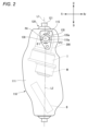
- FIG. 1 is a perspective view of an electric prosthetic leg 1 according to an embodiment of the present invention, as viewed obliquely from behind.
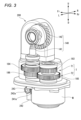
- FIG. 2 is a side view of the electric prosthetic leg 1 of FIG. 2 is a perspective view of an expansion/contraction device 200 of a first embodiment that can be mounted on the electric prosthetic leg 1 of FIG. 1 .
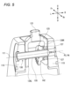
- FIG. 4 is a cross-sectional view of the expansion/contraction device 200 of FIG. 3 . 4 is a cross-sectional oblique view of a knee joint mechanism 130 of an electric prosthetic leg 1 incorporating the expansion/contraction device 200 of FIG. 3.
- 2 is a cross-sectional view of a two-way clutch 280.
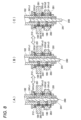
- FIGS. 1A and 1B are diagrams showing the operation of the operating mechanism 240, in which (A) is a diagram showing the state in which the intermittent portion 212 and the intermittent portion 222 are off, (B) is a diagram showing the state in which the intermittent portion 212 is off and the intermittent portion 222 is on, and (C) is a diagram showing the state in which the intermittent portion 212 is on and the intermittent portion 222 is off.
- 13A is a cross-sectional view showing a state in which the interrupter 222 is in an OFF state
- FIG. 13B is a diagram showing the position of the operating rod 241 at that time.
- 13A is a cross-sectional view showing a state in which the interrupter 222 is operated from OFF to ON
- 13B is a diagram showing the position of the operating rod 241 at that time.
- 1A is a cross-sectional view showing the forward rotation on state of the interrupter 222
- FIG. 1B is a diagram showing the position of the operating rod 241 at that time.
- 13A is a cross-sectional view showing the reverse ON state of the interrupter 222
- FIG. 13B is a diagram showing the position of the operating rod 241 at that time.
- 13A is a cross-sectional view showing a state in which the interrupter 222 is operated from on to off
- FIG. 13B is a diagram showing the position of the operating rod 241 at that time.
- 2 is a perspective view of an expansion/contraction device 200A of a second embodiment that can be mounted on the electric prosthetic leg 1 of FIG.
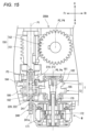
- FIG. 15 is a cross-sectional view of the expansion/contraction device 200A of FIG. 14.
- 13 is a cross-sectional oblique view of a knee joint mechanism 130 of an electric prosthetic leg 1 incorporating an expansion/contraction device 200A of a second embodiment.
- FIG. 4 is a perspective view of an expansion/contraction device 200B of a third embodiment that can be mounted on the electric prosthetic leg 1 of FIG.
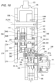
- FIG. 18 is a cross-sectional view of the expansion/contraction device 200B of FIG. 17.
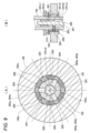
- 19 is an enlarged view of the planetary gear mechanism 260 in the expansion/contraction device 200B of FIG. 18. This is a cross-sectional view taken along line BB of Figure 19.
- 1A to 1C are diagrams illustrating the movement of a user and an electric prosthetic leg when ascending steps (step-ascending movement).
- 1A to 1C are diagrams illustrating the movement of a user and an electric prosthetic leg when walking on flat ground (flat ground walking movement).
- an electric prosthetic leg which is one embodiment of the joint device of the present invention, will be described with reference to the drawings.
- the front-rear direction, left-right direction, and up-down direction are defined based on the user of the electric prosthetic leg.
- the front of the electric prosthetic leg is indicated as Fr, the rear as Rr, the left side as L, the right side as R, the top as U, and the bottom as D.
- the electric prosthetic leg 1 is a prosthetic leg that is attached to the leg of a person without a knee, and includes a below-knee member 110 located below the knee, an above-knee member 120 attached to the thigh and located above the knee, a knee joint mechanism 130 that connects the below-knee member 110 and the above-knee member 120 in a manner that allows the angle between them to be changed, an expansion/contraction device 200 that can expand and contract the angle between the below-knee member 110 and the above-knee member 120, and a battery B that supplies power to the expansion/contraction device 200, etc.
- the above-knee member 120 comprises an adapter 121 that is connected to a socket (not shown), an upper wall portion 125 to which the adapter 121 is attached, and a pair of left and right side walls 126L, 126R that are connected to the upper wall portion 125.
- the socket is a joint member provided on the thigh portion 123 (see Figures 21 and 22), and by connecting the adapter 121 to the socket, the above-knee member 120 is integrated with the thigh portion 123.
- the knee-lower member 110 comprises a box-shaped main frame 111 that is open at the rear, a removable rear cover 113 that covers the rear opening of the main frame 111 in an openable and closable manner, and an adapter 122 attached to the underside of the main frame 111.
- the upper knee member 120 is attached to the upper part of the main frame 111 of the lower knee member 110 via a connecting shaft 135 that constitutes the knee joint mechanism 130, and the legs 114 extending downward are connected to the adapter 122 of the main frame 111.
- an expansion/contraction device 200 is provided that can expand and reduce the angle between the below-knee member 110 and the above-knee member 120.
- the expansion/contraction device 200 is configured to be able to expand and reduce the angle between the below-knee member 110 and the above-knee member 120 by meshing gears.
- the expansion/contraction device 200 comprises a motor M that outputs rotational power, a transmission T that transmits the power of the motor M, a bevel gear mechanism 140 that can expand and reduce the angle between the knee-below member 110 and the knee-above member 120, and a first interrupting mechanism 210 and a second interrupting mechanism 220 provided in the transmission T.
- the motor M is, for example, a permanent magnet type electric motor, and is disposed rearward of and below the transmission T.
- the motor M is a motor with a built-in gear mechanism that includes a motor body 171, a gear mechanism 172 that reduces the output rotation of the motor body 171, and an output shaft 170 that has a rotation axis Pm.
- the bevel gear mechanism 140 has a first bevel gear 141 that is positioned on the opposite side of the motor M with respect to the transmission T on the power transmission path of the motor M and is supported by the below-knee member 110, and a second bevel gear 142 that meshes with the first bevel gear 141 so as to be capable of transmitting rotation and is supported by the above-knee member 120.
- the first bevel gear 141 and the second bevel gear 142 constitute the bevel gear mechanism 140, each of which has a conical or truncated conical outer surface with teeth formed thereon.
- the rotation axis P1 of the first bevel gear 141 and the rotation axis P2 of the second bevel gear 142 are arranged to extend in directions perpendicular to each other. That is, the first bevel gear 141 and the second bevel gear 142 are configured to transmit rotation using a conical gear meshing mechanism. In this embodiment, the rotation is transmitted by meshing of two gears, but it may also be transmitted by friction between two rollers. That is, “rotation transmission possible” may be transmission by meshing of gears, or transmission by friction between rollers.
- the rotation axis P1 of the first bevel gear 141 and the rotation axis P2 of the second bevel gear 142 may or may not be on the same plane.
- a bevel gear mechanism 140 in which the two rotation axes P1 and P2 are not on the same plane is called a hypoid gear (registered trademark).
- the rotation axis P1 of the first bevel gear 141 is on the same line as the rotation axis P3 of the second shaft 182 described later.
- the rotation axis P2 of the second bevel gear 142 is collinear with the axis P4 of the connecting shaft 135.
- the rotation axis P1 of the first bevel gear 141 (second shaft 182) is arranged to extend in a direction parallel to the rotation axis Pm of the motor M
- the rotation axis P2 of the second bevel gear 142 is arranged to extend in a direction perpendicular to the rotation axis Pm of the motor M (vertical).
- the motor M is arranged in a position overlapping at least a portion of the second bevel gear 142 when viewed in the up-down direction perpendicular to the rotation axis P2 of the second bevel gear 142.
- the first bevel gear 141 is configured to be rotatable integrally with the second shaft 182, which is the output element of the transmission T described below.
- the first bevel gear 141 transmits the power of the motor M transmitted via the transmission T to the second bevel gear 142.
- the second bevel gear 142 is provided so as to be rotatable relative to the connecting shaft 135 and integrally with the above-knee member 120. More specifically, as shown in FIG. 2, the connecting shaft 135 is prevented from rotating by fitting the protrusion 135a of the connecting shaft 135 into the recess 115a provided in the through hole through which the connecting shaft 135 of the connecting shaft support plate 115 of the main frame 111 passes. As shown in FIG. 5, the second bevel gear 142 is integrally fastened to the right side wall 126R of the above-knee member 120 with a bolt 127. The side walls 126L and 126R are configured to be rotatable relative to the connecting shaft 135 by a bearing (not shown).
- the angle between the upper-knee member 120 and the lower-knee member 110 is defined by a first imaginary line L1 connecting the axis P4 of the connecting shaft 135 of the knee joint mechanism 130 and the adapter 121 of the upper-knee member 120, and a second imaginary line L2 extending vertically downward through the lower-knee member 110.
- first angle ⁇ 1 one side of one revolution is defined as the first angle ⁇ 1
- the other side is defined as the second angle ⁇ 2.
- the angle formed by the back of the knee of the user of the electric prosthetic leg 1 is the second angle ⁇ 2.
- the first angle ⁇ 1 has a value of approximately 175 degrees to 300 degrees
- the second angle ⁇ 2 has a value of approximately 60 degrees to 185 degrees.
- FIG. 2 shows the knee joint mechanism 130 in an extended state, with the first angle ⁇ 1 being approximately 175 degrees and the second angle ⁇ 2 being approximately 185 degrees.
- the second bevel gear 142 may have gears formed around its entire circumference, but in this embodiment, gears are formed only around a portion of the circumference to satisfy the range of motion of the second angle ⁇ 2.
- the transmission T includes a first transmission mechanism T1 that transmits the power of the motor M to the first bevel gear 141 at a first gear ratio, and a second transmission mechanism T2 that transmits the power of the motor M to the first bevel gear 141 at a second gear ratio different from the first gear ratio.
- the first transmission mechanism T1 and the second transmission mechanism T2 are switched between a power transmission disabled state and a power transmission enabled state by switching the disconnecting and connecting states of the interrupting mechanisms 210, 220.
- Such a transmission T has two power transmission paths with different gear ratios, making it possible to switch the movement speed and generated power of extension and flexion in the knee joint mechanism 130.
- the first gear ratio and the second gear ratio need only be different, and either the first gear mechanism T1 or the second gear mechanism T2 may be a reduction mechanism and the other a speed-up mechanism, or either one may be a constant speed mechanism and the other a reduction mechanism or speed-up mechanism, or both may be reduction mechanisms, or both may be speed-up mechanisms.
- the first gear ratio is the ratio of the post-shift rotation speed, which is the rotation speed on the anti-motor M side (first bevel gear 141 side) of the first speed change mechanism T1, to the pre-shift rotation speed, which is the rotation speed on the motor M side of the first speed change mechanism T1.
- the second gear ratio is the ratio of the post-shift rotation speed, which is the rotation speed on the anti-motor M side (first bevel gear 141 side) of the second speed change mechanism T2, to the pre-shift rotation speed, which is the rotation speed on the motor M side of the second speed change mechanism T2.
- the first speed change ratio of the first speed change mechanism T1 when the first speed change ratio of the first speed change mechanism T1 is smaller than 1, the rotation speed on the anti-motor M side (first bevel gear 141 side) decreases compared to the rotation speed on the motor M side, and the torque increases.
- the second speed change ratio of the second speed change mechanism T2 is greater than 1, the rotation speed on the anti-motor M side (first bevel gear 141 side) increases compared to the rotation speed on the motor M side, and the torque decreases.
- the first speed change ratio is set smaller than 1 and the second speed change ratio is set greater than 1, and the first speed change mechanism T1 is positioned above the second speed change mechanism T2.
- the first transmission mechanism T1 and the second transmission mechanism T2 include a first shaft 181 that is connected to the output shaft 170 of the motor M on an upward extension of the output shaft 170 so as to be rotatable together with the output shaft 170, and a second shaft 182 that is connected to the first bevel gear 141 on a downward extension of the first bevel gear 141 so as to be rotatable together with the first bevel gear 141.
- the first shaft 181 is an input element of the transmission T
- the second shaft 182 is an output element of the transmission T.
- the first speed change mechanism T1 includes a first drive gear 183 and a first driven gear 184 that mesh with each other.
- the first drive gear 183 is supported by the first shaft 181 so as to be able to rotate integrally with the first shaft 181, and the first driven gear 184 is supported by the second shaft 182 so as to be able to rotate relatively thereto.
- the first drive gear 183 and the first shaft 181 have the same rotation axis P5, and the first driven gear 184 and the second shaft 182 have the same rotation axis P3.
- the first speed change mechanism T1 of this embodiment is a reduction transmission mechanism in which the first drive gear 183 has a smaller diameter than the first driven gear 184, and can cause the first bevel gear 141 to expand and contract at a low speed with high torque.
- the second speed change mechanism T2 includes a second drive gear 185 and a second driven gear 186 that mesh with each other.
- the second drive gear 185 is supported by the first shaft 181 so as to be rotatable together with the first shaft 181
- the second driven gear 186 is supported by the second shaft 182 so as to be rotatable relative to the first shaft 182.
- the second drive gear 185 and the first shaft 181 have the same rotation axis P5, and the second driven gear 186 and the second shaft 182 have the same rotation axis P3.
- the second speed change mechanism T2 of this embodiment is a speed-increasing transmission mechanism in which the second drive gear 185 has a larger diameter than the second driven gear 186, and can expand and contract the first bevel gear 141 at high speed and with low torque.
- the second speed change mechanism T2 is disposed below the first speed change mechanism T1, but the second speed change mechanism T2 may be disposed above the first speed change mechanism T1.
- the first drive gear 183 and the second drive gear 185 which are supported by the first shaft 181 so as to be rotatable together, are formed as one unit, and are configured to be rotatable together.
- the rotation axis P3 of the first driven gear 184 and the second driven gear 186 which share a common rotation axis with the second shaft 182, is on the same line as the rotation axis P1 of the first bevel gear 141, and the first bevel gear 141, the first driven gear 184, and the second driven gear 186 are arranged in this order from above.
- the rotation axis P5 of the first drive gear 183 and the second drive gear 185 which share a common rotation axis with the first shaft 181, is on the same line as the rotation axis Pm of the motor M, and the first drive gear 183, the second drive gear 185, and the motor M are arranged in this order from above.
- the first interrupting mechanism 210 includes an interrupting part 212 provided between the first driven gear 184 and the second shaft 182.
- the second interrupting mechanism 220 includes an interrupting part 222 provided between the second driven gear 186 and the second shaft 182.
- These interrupting parts 212, 222 are arranged on the rotation axis P3 of the second shaft 182.
- the interrupting parts 212, 222 have a common configuration, and are each configured to be switchable between a disconnected state in which the power transmission path is disconnected and a connected state in which the power transmission path is connected. Details of the interrupting parts 212, 222 will be described later.
- the expansion/contraction device 200 is unitized and housed in the internal space of the main frame 111. Except for the second bevel gear 142, the expansion/contraction device 200 is fixed to the main frame 111 by a bracket (not shown). A battery B is fixed below the expansion/contraction device 200 in the internal space of the main frame 111.
- Each disconnecting unit 212, 222 has a common configuration and is configured to be switchable between a disconnected state in which the power transmission path is disconnected and a connected state in which the power transmission path is connected.
- Each disconnecting unit 212, 222 in this embodiment is configured using a two-way clutch 280 with a forced free function, as shown in Figure 6.
- the two-way clutch 280 includes a plurality of rollers 281 (three in this embodiment) arranged between the outer circumferential surface of the second shaft 182 and the inner circumferential surface of the gears 184 and 186, a retainer 282 that holds the rollers 281 at a predetermined interval, an operating mechanism 240, a plurality of pins 283 (three in this embodiment) that penetrate the second shaft 182 in the radial direction and are operated by the operating mechanism 240 to a forced free position and a forced free release position, and a plurality of guides 284 (three in this embodiment) that are provided on the retainer 282 and determine the relative rotational position of the retainer 282 with respect to the second shaft 182 when the pins 283 are in the forced free position.
- the rollers 281 may be balls or sprags.
- the radial distance A between the outer peripheral surface of the second shaft 182 and the inner peripheral surface of the gears 184 and 186 is smaller than the diameter B of the roller 281.
- flat portions 182a are formed at a predetermined interval in the circumferential direction on the outer peripheral portion of the second shaft 182, and the distance A is larger than the diameter B at the circumferential center side of the flat portions 182a.
- the roller 281 when the roller 281 is held in the circumferential center of the flat portion 182a, the roller 281 does not mesh with the outer peripheral surface of the second shaft 182 and the inner peripheral surfaces of the gears 184 and 186 (disengaged state), and relative rotation between the second shaft 182 and the gears 184 and 186 is permitted (forced free state).
- the roller 281 when the roller 281 is allowed to move circumferentially relative to the second shaft 182, the roller 281 meshes with the outer peripheral surface of the second shaft 182 and the inner peripheral surfaces of the gears 184 and 186 (engaged state), and the second shaft 182 and the gears 184 and 186 are connected so as to be able to rotate together in two directions (forced free release state).
- the retainer 282 is ring-shaped and rotatable relative to the second shaft 182 and the gears 184 and 186, and has a number of roller holding portions 282a that hold the rollers 281 and a number of guide holding portions 282b that hold the guides 284.
- multiple rubber balls 282c are embedded at a predetermined interval in the circumferential direction on the outer peripheral surface of the retainer 282. These rubber balls 282c prevent unintended free rotation in the forced free release state by generating appropriate friction between the gears 184, 186 and the retainer 282. Note that the member that generates friction between the gears 184, 186 and the retainer 282 is not limited to the rubber balls 282c, but may be an O-ring.
- the pin 283 has a conical protrusion 283a on its radially outer end
- the guide 284 has a conical recess 284a on its radially inner end face that fits (engages) with the protrusion 283a.
- the operating mechanism 240 includes an operating rod 241 that is capable of operating the interrupting parts 212, 222 intermittently, and a servo motor 242 (see FIG. 3) that moves the operating rod 241 linearly.
- the servo motor 242 is disposed adjacent to the motor M. In other words, the servo motor 242 is disposed on the same side as the motor M with respect to the transmission T.
- the servo motor 242 and the motor M may be formed as a unit.
- the second shaft 182 is a hollow shaft having an internal space S extending in the direction of the rotation axis (also referred to as the up-down direction), and an operating rod 241 is disposed in this internal space S.
- a rack 241a is provided on the lower end of the operating rod 241 that is exposed from the internal space S.
- a pinion 243 provided on the output shaft 242a of a servo motor 242 meshes with the rack 241a, and the up-down position of the operating rod 241 is changed in response to the drive of the servo motor 242.
- the outer periphery of the operating rod 241 is formed with small diameter portions 241b1, 241b2 and large diameter portions 241c1-241c3, which will be described later, and abut against the inner diameter end portion of the pin 283.
- the small diameter portions 241b1, 241b2 and large diameter portions 241c1-241c3 move the pin 283 forward and backward in the radial direction of the second shaft 182, thereby switching the state of the interrupted portions 212, 222.
- the outer periphery of the operating rod 241 is formed with a first large diameter portion 241c1, a first small diameter portion 241b1, a second large diameter portion 241c2, a second small diameter portion 241b2, and a third large diameter portion 241c3 at a predetermined length and intervals, in that order from the top.
- the operating rod 241 is provided so as to be able to simultaneously control the two interrupted portions 212, 222, but may be provided separately for each of the interrupted portions 212, 222.
- the interrupters 212 and 222 can be switched between a forced free state (hereinafter referred to as the OFF state) and a forced free release state (hereinafter referred to as the ON state) by the operating mechanism 240.
- a forced free state hereinafter referred to as the OFF state
- a forced free release state hereinafter referred to as the ON state
- the second large diameter portion 241c2 pushes the pin 283 of the interrupted portion 212 in the outward direction
- the third large diameter portion 241c3 pushes the pin 283 of the interrupted portion 222 in the outward direction, thereby turning off the interrupted portion 222 and the interrupted portion 212.
- the first small diameter portion 241b1 allows the pin 283 of the interrupted portion 212 to return in the inner diameter direction, while the third large diameter portion 241c3 pushes the pin 283 of the interrupted portion 222 in the outer diameter direction, thereby turning the interrupted portion 212 to the ON state and the interrupted portion 222 to the OFF state.
- the first large diameter portion 241c1 pushes the pin 283 of the interrupted portion 212 in the outer diameter direction while the second small diameter portion 241b2 allows the pin 283 of the interrupted portion 222 to return in the inner diameter direction, thereby turning the interrupted portion 212 to the OFF state and the interrupted portion 222 to the ON state.
- the roller 281 is an engaging element
- the operating rod 241, the pin 283, the guide 284, and the retainer 282 correspond to an operating part that operates the engaging element (roller 281) between an engaged state and a disengaged state.
- the pin 283, the guide 284, and the retainer 282 are actuators that move the engaging element (roller 281)
- the operating rod 241 corresponds to an actuator that is provided to be able to operate the actuator.
- the pin 283 is an advancing/retracting element that is provided to be able to move forward and backward along the radial direction, and the guide 284 and the retainer 282 correspond to a holder that holds the advancing/retracting element (pin 283) so that it can move forward and backward.
- FIGS. 1 and (B) of Figure 10 show the state in which the operating rod 241 has moved from a position in which the second large diameter portion 241c2 pushes the pin 283 of the interrupted portion 212 in the outward direction to a position in which the first small diameter portion 241b1 allows the pin 283 to return in the inward direction.
- the roller 281 is held in the circumferential center of the flat portion 182a, so the roller 281 does not mesh with the outer peripheral surface of the second shaft 182 and the inner peripheral surface of the first driven gear 184, and the second shaft 182 and the first driven gear 184 are allowed to rotate relative to each other in an OFF state.
- the interrupting parts 212 and 222 are provided on the second shaft 182 side, but they may be provided on the first shaft 181 side. That is, the interrupting part 212 of the first interrupting mechanism 210 is provided between the first drive gear 183 and the first shaft 181, and the interrupting part 222 of the second interrupting mechanism 220 is provided between the second drive gear 185 and the first shaft 181. Also, the interrupting parts 212 and 222 may be provided on both the second shaft 182 side and the first shaft 181 side.
- FIG. 21 is a diagram showing the movement of the user and the electric prosthetic leg 1 when ascending stairs (ascending movement).
- (A) to (D) show the stance phase
- (D) to (E) show the transition phase from stance to early swing
- (E) to (G) show the early swing phase
- (G) show the transition phase from early swing to late swing and the late swing phase
- (H) show the transition phase from late swing to stance and the stance phase.
- the transmission T is in the first shift state in which the operating rod 241 is in the middle position (FIG. 8B).
- the interrupter 212 is in the ON state and the interrupter 222 is in the OFF state, and the motor M and the bevel gear mechanism 140 are in a power transmission state via the first shift mechanism T1.
- This extending power is a high-torque power that is decelerated by the first speed change mechanism T1, so that even if a large load is placed on the electric prosthesis 1 when the electric prosthesis 1 is put forward to climb stairs, the knee joint mechanism 130 can be reliably extended from a bent state.
- the knee joint mechanism 130 needs to be bent (raised) from an extended position while a load is being applied to the healthy leg, as shown in (E) to (H) of Figure 21.
- a large amount of power is not required, but quick movement is required.
- the transmission T is in the second shift state in which the operating rod 241 is in the lower position (FIG. 8(C)).
- the interrupter 212 is in the OFF state and the interrupter 222 is in the ON state, and the motor M and the bevel gear mechanism 140 are in a power transmission state via the second shift mechanism T2.
- Figure 22 shows the movement of the user and the powered prosthetic leg when walking on flat ground (flat ground walking movement).
- Figure 22 (A) to (D) show the stance phase, (D) shows the transition phase from stance to swing, (E) to (H) show the swing phase, and (H) shows the transition phase from swing to stance and the stance phase.
- the transmission T is in the second speed change state in which the operating rod 241 is in the lower position ((C) of FIG. 8).
- the interrupter 212 is in the off state and the interrupter 222 is in the on state, and the motor M and the bevel gear mechanism 140 are in a power transmission state via the second speed change mechanism T2.
- the transmission T is in a state in which the operating rod 241 is in the upper position ((A) of FIG. 8).
- the interrupter 212 is in the OFF state and the interrupter 222 is in the OFF state, and the motor M and the bevel gear mechanism 140 are in a state in which power transmission is disabled. This allows the user of the electric prosthetic leg 1 to swing out their leg smoothly.
- the expansion/contraction device 200 of the first embodiment is configured to be able to expand and contract the angle between the below-knee member 110 and the above-knee member 120 using a rotational mechanism including a bevel gear mechanism 140 rather than a telescopic device such as a spindle mechanism, so the longitudinal (vertical) length of the electric prosthetic leg 1 can be made smaller.
- the rotational mechanism is completed by the bevel gear mechanism 140 in which the first bevel gear 141 and the second bevel gear 142 mesh, so that a complex structure can be avoided.
- the motor M is positioned in a position that overlaps at least a portion of the second bevel gear 142 when viewed in the vertical direction perpendicular to the rotation axis P2 of the second bevel gear 142, so that the protrusion of the motor M is suppressed and the electric prosthetic leg 1 can be made even smaller.
- the expansion/contraction device 200A includes a motor M that outputs rotational power, a transmission T that transmits the power of the motor M, a worm gear mechanism 150 that can expand and reduce the angle between the knee-below member 110 and the knee-above member 120, and a first interrupting mechanism 210 and a second interrupting mechanism 220 provided in the transmission T.
- the configuration other than the worm gear mechanism 150 is the same as that of the expansion/contraction device 200 of the first embodiment, and therefore a description thereof will be omitted.
- the worm gear mechanism 150 has a worm gear 151 that is positioned on the opposite side of the motor M with respect to the transmission T on the power transmission path of the motor M and is supported by the knee-below member 110, and a worm wheel 152 that meshes with the worm gear 151 so as to be able to transmit rotation and is supported by the knee-above member 120.
- the worm gear 151 and the worm wheel 152 each constitute the worm gear mechanism 150 (screw gear mechanism) with teeth formed on the cylindrical outer surface.
- the worm wheel (helical gear) can also be substituted with a thin spur gear.
- the rotation axis P1 of the worm gear 151 (second shaft 182) and the rotation axis P2 of the worm wheel 152 are arranged to extend in directions perpendicular to each other.
- the rotation axis Pm of the motor M In relation to the rotation axis Pm of the motor M, the rotation axis P1 of the worm gear 151 is arranged to extend in a direction parallel to the rotation axis Pm of the motor M, and the rotation axis P2 of the worm wheel 152 is arranged to extend in a direction perpendicular to the rotation axis Pm of the motor M.
- the motor M is arranged in a position that overlaps at least a portion of the worm wheel 152 when viewed in the up-down direction perpendicular to the rotation axis P2 of the worm wheel 152.
- the worm gear 151 is configured to be rotatable integrally with the second shaft 182, which is the output element of the transmission T.
- the worm gear 151 transmits the power of the motor M transmitted via the transmission T to the worm wheel 152.
- the worm wheel 152 is provided so as to be rotatable relative to the connecting shaft 135 and integrally rotate with the above-knee member 120.
- the worm wheel 152 is provided so as to be rotatable relative to the connecting shaft 135, which is prevented from rotating by the connecting shaft support plate 115 of the main frame 111, and integrally rotate with the above-knee member 120, similar to the second bevel gear 142 of the first embodiment. That is, as shown in FIG. 16, the worm wheel 152 is integrally fastened to the left side wall portion 126L by a bolt 127.
- the side walls 126L and 126R are configured to be rotatable relative to the connecting shaft 135 by a bearing (not shown).
- the above-knee member 120 rotates around the connecting shaft 135 as the worm wheel 152 meshing with the worm gear 151 rotates. Therefore, the angle between the above-knee member 120 and the below-knee member 110 changes.
- the expansion/contraction device 200A is configured to be able to expand and reduce the angle between the knee-below member 110 and the knee-above member 120 using a rotational mechanism including a worm gear mechanism 150, rather than a telescopic device such as a spindle mechanism, so that the longitudinal (vertical) length of the electric prosthetic leg 1 can be made smaller.
- the rotational mechanism is completed by the worm gear mechanism 150 in which the worm gear 151 and the worm wheel 152 mesh, so that a complex structure can be avoided.
- the motor M is positioned in a position that overlaps at least a portion of the worm wheel 152 when viewed in the vertical direction perpendicular to the rotation axis P2 of the worm wheel 152, so that the protrusion of the motor M is suppressed and the electric prosthetic leg 1 can be made even smaller.
- the expansion/contraction device 200B comprises a motor M that outputs rotational power, a transmission T that transmits the power of the motor M, a spur gear mechanism 160 that can expand and reduce the angle between the knee-below member 110 and the knee-above member 120, an intermediate gear mechanism 270 provided between the transmission T and the spur gear mechanism 160, and a first interrupting mechanism 210 and a second interrupting mechanism 220 provided in the transmission T.
- the configuration of the motor M and the transmission T is the same as in the first and second embodiments, but the layout of the motor M and the transmission T is different. That is, in the first embodiment of the expansion/contraction device 200 and the second embodiment of the expansion/contraction device 200A, the rotation axis Pm of the motor M and the rotation axis P5 of the first shaft 181 and the rotation axis P3 of the second shaft 182 of the transmission T are arranged so as to be perpendicular to the axis P4 of the connecting shaft 135, but in the third embodiment of the expansion/contraction device 200B, the rotation axis Pm of the motor M and the rotation axis P5 of the first shaft 181 and the rotation axis P3 of the second shaft 182 of the transmission T are arranged so as to extend in directions parallel to each other with respect to the axis P4 of the connecting shaft 135.
- the rotation axis Pm of the motor M and the rotation axis P5 of the first shaft 181 and the rotation axis P3 of the second shaft 182 of the transmission T are arranged to extend in the vertical direction relative to the axis P4 of the connecting shaft 135 extending in the left-right direction, but in the third embodiment of the expansion/contraction device 200B, the rotation axis Pm of the motor M and the rotation axis P5 of the first shaft 181 and the rotation axis P3 of the second shaft 182 of the transmission T are arranged to extend in the left-right direction relative to the axis P4 of the connecting shaft 135 extending in the left-right direction.
- the configurations of the motor M and the transmission T are the same as those of the first and second embodiments, so detailed explanations will be omitted.
- the spur gear mechanism 160 has a pinion gear 161 that is positioned on the opposite side of the motor M with respect to the transmission T on the power transmission path of the motor M and is supported by the knee-lower member 110, and a knee shaft gear 162 that is meshed with the pinion gear 161 so as to be capable of transmitting rotation and is supported by the knee-upper member 120.
- the rotation axis P1 of the pinion gear 161 and the rotation axis P2 of the knee axis gear 162 are arranged to extend in directions parallel to each other. That is, the pinion gear 161 and the knee axis gear 162 are configured to transmit rotation using a spur gear meshing mechanism. In this embodiment, rotation is transmitted by meshing of two gears, but rotation may also be transmitted by friction between two rollers. In other words, “capable of transmitting rotation” may mean transmission by meshing of gears, transmission by friction between rollers, etc.
- the rotation axis P1 of the pinion gear 161 and the rotation axis P2 of the knee shaft gear 162 are arranged to extend in a direction parallel to the rotation axis Pm of the motor M.
- the pinion gear 161 is configured to be able to rotate integrally with the planetary carrier 264, which is the output element of the planetary gear mechanism 260 described below.
- the pinion gear 161 transmits the power of the motor M, transmitted via the transmission T and the intermediate gear mechanism 270, to the knee shaft gear 162.
- the pinion gear 161 is positioned so that it fits within the extension length of the connecting shaft 135 when viewed in the up-down direction perpendicular to the rotation axis P1 of the pinion gear 161.
- the extension length of the connecting shaft 135 is the distance between the left end and right end of the connecting shaft 135 as shown in FIG. 16.
- the knee axis gear 162 like the second bevel gear 142 in the first embodiment and the worm wheel 152 in the second embodiment, is mounted so as to be rotatable relative to the connecting shaft 135, which is stopped by the connecting shaft support plate 115 of the main frame 111, and rotatable integrally with the upper-knee member 120.
- the knee axis gear 162 is a spur gear, and the gear is formed only on a part of the circumference to satisfy the movable range of the second angle ⁇ 2 described above, giving it a sector shape like a circular spur gear with most of the circumference missing.
- the knee axis gear 162 which meshes with the pinion gear 161, rotates, causing the upper-knee member 120 to rotate around the connecting shaft 135. Therefore, the angle between the upper-knee member 120 and the lower-knee member 110 changes.
- the intermediate gear mechanism 270 comprises an intermediate drive gear 273 that rotates integrally with the second shaft 182, which is the output element of the transmission T; an intermediate shaft 274 having a rotation axis P6 parallel to the rotation axis P3 of the second shaft 182; and an intermediate driven gear 275 that is attached to rotate integrally with the intermediate shaft 274 and meshes with the intermediate drive gear 273.
- the rotation axis P6 of the intermediate shaft 274 coincides with the rotation axis P1 of the pinion gear 161.
- the intermediate drive gear 273 and the intermediate driven gear 275 are positioned to fit within the extension length of the connecting shaft 135 when viewed in the up-down direction perpendicular to the rotation axis P1 of the pinion gear 161.
- the planetary gear mechanism 260 is disposed on the rotation axis P6 of the intermediate shaft 274, as shown in Figs. 19 and 20.
- the planetary gear mechanism 260 has a sun gear 261 and a ring gear 262 that have the same rotation axis as the intermediate shaft 274, a plurality of planetary gears 263 that mesh with the sun gear 261 and the ring gear 262, and a planetary carrier 264 that supports the plurality of planetary gears 263 so that they can rotate and revolve.
- the three rotating elements consisting of the sun gear 261, the ring gear 262, and the planetary carrier 264 satisfy a collinear relationship in which their rotational speeds are always aligned on a single straight line in the speed nomogram.
- the planetary gear mechanism 260 is disposed so as to fit within the extension length of the connecting shaft 135 when viewed in the vertical direction perpendicular to the rotation axis P1 of the pinion gear 161.
- the planetary carrier 264 has a pair of left and right carrier plates 264L, 264R connected by left and right connecting shafts 264a. Between the carrier plates 264L, 264R, the planetary gear 263 is supported by a pinion rotation shaft 263a so that it can rotate and revolve.
- the sun gear 261 is connected to the intermediate shaft 274 so as to rotate together with it, and the pinion gear 161 is connected to the planetary carrier 264 so as to rotate together with it.
- a ring fixing hole 262a is provided in the ring gear 262, and the ring gear 262 is fixed to the main frame 111.
- the power of the motor M transmitted from the transmission T via the intermediate gear mechanism 270 is input to the sun gear 261 of the planetary gear mechanism 260.
- the rotation of the sun gear 261 is decelerated and transmitted to the planetary carrier 264, and then transmitted to the knee shaft gear 162 via the pinion gear 161.
- the expansion/contraction device 200B of the third embodiment is configured to be able to expand and contract the angle between the knee-lower member 110 and the knee-higher member 120 using a rotational mechanism including a planetary gear mechanism 260, rather than a telescopic device such as a spindle mechanism, and therefore the longitudinal (vertical) length of the electric prosthetic leg 1 can be made smaller.
- the rotational mechanism is completed by the planetary gear mechanism 260, the intermediate gear mechanism 270, and the spur gear mechanism 160, so that the structure can be prevented from becoming complicated.
- the pinion gear 161, the intermediate drive gear 273, the intermediate driven gear 275, and the planetary gear mechanism 260 are each arranged so as to fit within the extension length of the connecting shaft 135 when viewed in the vertical direction perpendicular to the rotation axis P1 of the pinion gear 161, so that the electric prosthetic leg 1 can be made even smaller in the extension direction of the connecting shaft 135 (the left-right direction in this embodiment).
- a prosthetic leg device (electric prosthetic leg) applied to a knee joint is exemplified as one embodiment of a coupling device in which the disconnecting device of the present invention is used, but the present invention is not limited to this, and may also be a prosthetic limb device (electric prosthetic limb) applied to an elbow joint, and the subject of the attachment may be an animal other than a human, or may be a robot.
- the below-knee member 110 of the above embodiment becomes the distal side of the subject of attachment relative to the above-knee member 120, i.e., the forearm.
- first member (knee-below member 110); A second member (above-knee member 120); a connecting portion (knee joint mechanism 130) that connects the first member and the second member in a manner that allows an angle between the first member and the second member to be changed;
- a joint device (electric prosthetic leg 1) including an expansion/contraction device (expansion/contraction device 200) capable of expanding and contracting the angle between the first member and the second member,
- the expansion/contraction device is A power source (motor M) and a power transmission unit (transmission T) that transmits the power of the power source,
- the power transmission unit includes: a first power transmission path (first speed change mechanism T1) that transmits the power at a first speed change ratio; a second power transmission path (second speed change mechanism T2) that transmits the power at a second speed change ratio different from the first speed change ratio,
- the expansion/contraction device is a first interrupting mechanism (first interrupting mechanism 210) that switches between interruption and connection of power in the first power transmission
- the connecting part can be extended and bent via the power transmission part that transmits the power of the power source.
- the power transmission part has two power transmission paths with different gear ratios, it is possible to switch the operating speed of extension and bending at the connecting part and the generated power.
- the expansion/contraction device is a first rotating body (a first bevel gear 141, a worm gear 151, a pinion gear 161) that is disposed on the power transmission path on the opposite side of the power source with respect to the power transmission unit and is supported by the first member;
- a coupling device having a second rotating body (a second bevel gear 142, a worm wheel 152, a knee shaft gear 162) that is arranged so as to be capable of transmitting rotation to the first rotating body and is supported by the second member.
- the expansion and contraction of the angle formed by the expansion/contraction device is achieved by the rotational transmission between the first rotating body supported by the first member and the second rotating body supported by the second member, so the coupling device can be made smaller than a spindle mechanism.
- “capable of transmitting rotation” may mean transmission by meshing gears or transmission by friction between rollers, etc.
- the coupling device according to (2), The first rotating body and the second rotating body are A coupling device in which a first rotation axis (rotation axis P1) that is the rotation axis of the first rotating body and a second rotation axis (rotation axis P2) that is the rotation axis of the second rotating body are arranged to extend in directions perpendicular to each other.
- rotation can be transmitted using a conical gear meshing mechanism or a conical friction wheel mechanism.
- the coupling device according to (3), The first rotating body and the second rotating body constitute a screw gear mechanism (worm gear mechanism 150) having teeth formed on a cylindrical outer surface.
- the power source is a rotational power source (motor M), A coupling device, wherein a third rotation axis (rotation axis Pm) which is a rotation axis of the rotational power source is arranged to extend parallel to the first rotation axis.
- the expansion/contraction device can be configured simply.
- the coupling device according to (2), The first rotating body and the second rotating body are A coupling device in which a first rotation axis (rotation axis P1) that is the rotation axis of the first rotating body and a second rotation axis (rotation axis P2) that is the rotation axis of the second rotating body are arranged to extend in directions parallel to each other.
- rotation can be transmitted using a gear meshing mechanism, a cylindrical friction wheel, or a grooved friction wheel mechanism.
- the coupling device is a rotational power source (motor M), A coupling device, wherein a third rotation axis (rotation axis Pm) which is the rotation axis of the rotational power source is disposed so as to extend in a direction parallel to the first rotation axis and the second rotation axis.
- the expansion/contraction device can be configured simply.
- the power transmission unit includes: a third rotor (first drive gear 183) disposed on the first power transmission path; a fourth rotor (second drive gear 185) that is disposed on the second power transmission path and is disposed on the same fourth rotation axis (rotation axis P5) as the third rotor; a fifth rotor (first driven gear 184) that is disposed on the first power transmission path and is capable of transmitting rotation to the third rotor; a sixth rotating body (second driven gear 186) that is arranged on the second power transmission path, is arranged on the same fifth rotation axis (rotation axis P3) as the fifth rotating body, and is arranged to be capable of transmitting rotation to the fourth rotating body.
- the rotational axis of the third and fourth rotating bodies is the same as the rotational axis of the fifth and sixth rotating bodies, respectively, thereby making it possible to reduce the size of the expansion/contraction device.
- the expansion/contraction device can be made smaller.
- the coupling device according to (10), The first rotating body, the fifth rotating body, and the sixth rotating body are Coupling devices arranged in this order on the same axis from one side.
- the first power transmission path and the second power transmission path can be arranged close to each other.
- the power source is a rotational power source (motor M), A coupling device, wherein a third rotation axis (rotation axis Pm) which is a rotation axis of the rotational power source is arranged coaxially with the fourth rotation axis.
- the power source, the third rotor, and the fourth rotor have the same rotation axis, making it possible to reduce the size of the expansion/contraction device.
- the coupling device according to (12), The third rotating body, the fourth rotating body, and the rotational power source are Coupling devices arranged in this order on the same axis from one side.
- the first power transmission path and the second power transmission path can be arranged close to each other.
- the power transmission unit includes: A coupling device having a seventh rotating body (second shaft 182) connected to the fifth rotating body via the first interrupting mechanism and connected to the sixth rotating body via the second interrupting mechanism.
- the first interruption mechanism and the second interruption mechanism can be concentrated around the seventh rotor.
- the first interrupting mechanism and the second interrupting mechanism can be concentrated on the fifth rotation axis.
- the first interrupting mechanism includes: A first engaging element (roller 281) disposed between the fifth rotating body and the seventh rotating body; a first operating portion (an operating rod 241, a pin 283, a guide 284, a retainer 282) that operates the first engaging element between an engaged state and a disengaged state
- the second interrupting mechanism includes: A second engaging element (roller 281) disposed between the sixth rotating body and the seventh rotating body; a second operating portion (operating rod 241, pin 283, guide 284, retainer 282) that operates the second engaging element between an engaged state and a disengaged state.
- the first operating unit can switch the first interrupting mechanism between an ON state and an OFF state
- the second operating unit can switch the second interrupting mechanism between an ON state and an OFF state
- the coupling device is A first actuator (pin 283, guide 284, retainer 282) that moves the first engagement element; A first operating element (operation rod 241) that is provided so as to be able to operate the first actuator,
- the second operation unit is A second actuator (pin 283, guide 284, retainer 282) that moves the second engaging element; A coupling device having a second operating element (operating rod 241) that is provided so as to be able to operate the second actuator.
- the first operating element and the first actuator constitute a first operating section
- the second operating element and the second actuator constitute a second operating section
- the coupling device is A first movable member (pin 283) that is movable forward and backward along a radial direction relative to the fifth rotation axis; a first holder (a guide 284, a retainer 282) that holds the first advancing/retracting element so that the first advancing/retracting element can be moved forward and backward;
- the second actuator is a second reciprocating element (pin 283) that is provided so as to be movable forward and backward along a radial direction relative to the fifth rotation axis, and a second holder (guide 284, retainer 282) that holds the second reciprocating element so as to be movable forward and backward, the first operator is provided to be movable back and forth along the fifth rotation axis, and an outer periphery of the first operator is provided to abut against an end of the first advance/retract member on a side of the fifth rotation axis, The second operator is arranged to be movable back and forth along the fifth rotation axis
- the first operator which is movable back and forth along the rotation axis, can move the first movable member back and forth along the radial direction
- the second operator which is movable back and forth along the same rotation axis, can move the second movable member back and forth along the radial direction
- the seventh rotor is hollow so as to have an internal space (internal space S) extending in a rotation axis direction of the seventh rotor, A coupling device, wherein the first operator and the second operator are integrally formed and disposed to be located in the internal space.
- the first operator and the second operator are integrally formed, thereby reducing the number of parts.
- the expansion/contraction device is A coupling device having a drive unit (servo motor 242) that drives the first operator and the second operator that are integrally formed.
- the drive section and power source can be arranged together, making the drive unit more compact.
- the number of parts can be reduced.
- the expansion/contraction device is A coupling device having an eighth rotating body (intermediate driven gear 275) arranged on a sixth rotating axis (rotation axis P6) that extends parallel to the fifth rotating axis and is arranged so as to be capable of transmitting rotation to the seventh rotating body.
- the rotation of the seventh rotating body can be transmitted to the eighth rotating body.
- the coupling device according to (23), The expansion/contraction device is A coupling device having a speed change mechanism (planetary gear mechanism 260) that is arranged on the sixth rotation axis and is capable of transmitting rotation to the eighth rotating body.
- a speed change mechanism planetary gear mechanism 260
- the rotation of the eighth rotor can be changed by a speed change mechanism.
- the rotation of the eighth rotating body whose speed has been changed can be transmitted to the first rotating body.
- a coupling device according to any one of (23) to (25),
- the first rotating body and the second rotating body are
- the first rotor is disposed such that a first rotation axis which is a rotation axis of the first rotor and a second rotation axis which is a rotation axis of the second rotor extend in directions parallel to each other,
- a coupling device that is arranged so as to fit within the extension length of the connection shaft (connection shaft 135) of the connection portion when viewed in a direction perpendicular to the first rotation axis.
- the coupling device can be made smaller in size in the extension direction of the connecting shaft.
- the eighth rotating body is A coupling device arranged so as to fit within the extension direction length when viewed in a direction perpendicular to the first rotation axis.
- the coupling device can be made smaller in size in the extension direction of the connecting shaft.
- a coupling device according to (26) dependent on (24), The speed change mechanism is disposed so as to be contained within the extension direction length when viewed in a direction perpendicular to the first rotation axis.
- the coupling device can be made smaller in size in the extension direction of the connecting shaft.
- a coupling device according to any one of (3) to (6), The power source is arranged at a position overlapping at least a portion of the second rotating body when viewed in a direction perpendicular to the second rotation axis.
- the coupling device can be made smaller.
Landscapes
- Health & Medical Sciences (AREA)
- Engineering & Computer Science (AREA)
- Transplantation (AREA)
- Vascular Medicine (AREA)
- Animal Behavior & Ethology (AREA)
- Cardiology (AREA)
- Biomedical Technology (AREA)
- Heart & Thoracic Surgery (AREA)
- General Engineering & Computer Science (AREA)
- Life Sciences & Earth Sciences (AREA)
- Oral & Maxillofacial Surgery (AREA)
- General Health & Medical Sciences (AREA)
- Public Health (AREA)
- Veterinary Medicine (AREA)
- Orthopedic Medicine & Surgery (AREA)
- Mechanical Engineering (AREA)
- Transmission Devices (AREA)
- Manipulator (AREA)
Priority Applications (3)
| Application Number | Priority Date | Filing Date | Title |
|---|---|---|---|
| EP23907108.7A EP4621261A1 (en) | 2022-12-21 | 2023-12-20 | Coupling device |
| JP2024566116A JPWO2024135748A1 (https=) | 2022-12-21 | 2023-12-20 | |
| CN202380087663.9A CN120569578A (zh) | 2022-12-21 | 2023-12-20 | 接头装置 |
Applications Claiming Priority (2)
| Application Number | Priority Date | Filing Date | Title |
|---|---|---|---|
| JP2022-204448 | 2022-12-21 | ||
| JP2022204448 | 2022-12-21 |
Publications (1)
| Publication Number | Publication Date |
|---|---|
| WO2024135748A1 true WO2024135748A1 (ja) | 2024-06-27 |
Family
ID=91588718
Family Applications (1)
| Application Number | Title | Priority Date | Filing Date |
|---|---|---|---|
| PCT/JP2023/045795 Ceased WO2024135748A1 (ja) | 2022-12-21 | 2023-12-20 | 継手装置 |
Country Status (4)
| Country | Link |
|---|---|
| EP (1) | EP4621261A1 (https=) |
| JP (1) | JPWO2024135748A1 (https=) |
| CN (1) | CN120569578A (https=) |
| WO (1) | WO2024135748A1 (https=) |
Citations (3)
| Publication number | Priority date | Publication date | Assignee | Title |
|---|---|---|---|---|
| JPH1119105A (ja) | 1997-07-04 | 1999-01-26 | Nagasaki Kanae Gishi Seisakusho:Kk | 義 足 |
| JP2022133999A (ja) * | 2021-03-02 | 2022-09-14 | 本田技研工業株式会社 | 継手装置 |
| WO2022260098A1 (ja) * | 2021-06-11 | 2022-12-15 | 本田技研工業株式会社 | 継手装置 |
-
2023
- 2023-12-20 JP JP2024566116A patent/JPWO2024135748A1/ja active Pending
- 2023-12-20 WO PCT/JP2023/045795 patent/WO2024135748A1/ja not_active Ceased
- 2023-12-20 CN CN202380087663.9A patent/CN120569578A/zh active Pending
- 2023-12-20 EP EP23907108.7A patent/EP4621261A1/en active Pending
Patent Citations (3)
| Publication number | Priority date | Publication date | Assignee | Title |
|---|---|---|---|---|
| JPH1119105A (ja) | 1997-07-04 | 1999-01-26 | Nagasaki Kanae Gishi Seisakusho:Kk | 義 足 |
| JP2022133999A (ja) * | 2021-03-02 | 2022-09-14 | 本田技研工業株式会社 | 継手装置 |
| WO2022260098A1 (ja) * | 2021-06-11 | 2022-12-15 | 本田技研工業株式会社 | 継手装置 |
Non-Patent Citations (1)
| Title |
|---|
| See also references of EP4621261A1 |
Also Published As
| Publication number | Publication date |
|---|---|
| CN120569578A (zh) | 2025-08-29 |
| EP4621261A1 (en) | 2025-09-24 |
| JPWO2024135748A1 (https=) | 2024-06-27 |
Similar Documents
| Publication | Publication Date | Title |
|---|---|---|
| JP7705855B2 (ja) | 継手装置 | |
| JP7497360B2 (ja) | 継手装置 | |
| WO2022260098A1 (ja) | 継手装置 | |
| WO2021189677A1 (zh) | 仿生机器人并联驱动关节的肢体结构和仿生机器人 | |
| JP7604682B2 (ja) | 動力伝達装置 | |
| WO2024135748A1 (ja) | 継手装置 | |
| WO2024204613A1 (ja) | 継手装置及び駆動装置 | |
| WO2024204612A1 (ja) | 動力伝達装置及び継手装置 | |
| CN117341856A (zh) | 一种仿生机械腿 | |
| JP7830109B2 (ja) | 断続装置 | |
| WO2024053687A1 (ja) | 継手装置、継手装置の制御方法、継手装置の制御プログラム、及び、該制御プログラムを記憶した記憶媒体 | |
| JP2024179347A (ja) | 動力伝達装置 | |
| JP7733982B2 (ja) | 継手装置 | |
| JP2023088641A (ja) | 動力伝達装置 | |
| WO2023112999A1 (ja) | 断続装置及び継手装置 | |
| JP7851717B2 (ja) | 断続装置 | |
| JP2024179342A (ja) | 断続装置 | |
| JP2023088643A (ja) | 動力伝達装置 | |
| JP7674857B2 (ja) | 継手装置 | |
| KR102095052B1 (ko) | 로봇관절 | |
| JP2023144954A (ja) | 断続装置 | |
| JP2025142529A (ja) | 断続装置 | |
| JP7734210B2 (ja) | 断続装置 | |
| JP2026064502A (ja) | 動力伝達装置 | |
| CN115303382A (zh) | 足式机器人关节驱动装置及方法 |
Legal Events
| Date | Code | Title | Description |
|---|---|---|---|
| 121 | Ep: the epo has been informed by wipo that ep was designated in this application |
Ref document number: 23907108 Country of ref document: EP Kind code of ref document: A1 |
|
| WWE | Wipo information: entry into national phase |
Ref document number: 2024566116 Country of ref document: JP |
|
| WWE | Wipo information: entry into national phase |
Ref document number: 202380087663.9 Country of ref document: CN |
|
| WWE | Wipo information: entry into national phase |
Ref document number: 2023907108 Country of ref document: EP |
|
| ENP | Entry into the national phase |
Ref document number: 2023907108 Country of ref document: EP Effective date: 20250620 |
|
| NENP | Non-entry into the national phase |
Ref country code: DE |
|
| WWP | Wipo information: published in national office |
Ref document number: 202380087663.9 Country of ref document: CN |
|
| WWP | Wipo information: published in national office |
Ref document number: 2023907108 Country of ref document: EP |