WO2024134900A1 - 二次元スキャンセンサ - Google Patents
二次元スキャンセンサ Download PDFInfo
- Publication number
- WO2024134900A1 WO2024134900A1 PCT/JP2022/047734 JP2022047734W WO2024134900A1 WO 2024134900 A1 WO2024134900 A1 WO 2024134900A1 JP 2022047734 W JP2022047734 W JP 2022047734W WO 2024134900 A1 WO2024134900 A1 WO 2024134900A1
- Authority
- WO
- WIPO (PCT)
- Prior art keywords
- unit
- orientation
- light
- sensor
- dimensional
- Prior art date
- Legal status (The legal status is an assumption and is not a legal conclusion. Google has not performed a legal analysis and makes no representation as to the accuracy of the status listed.)
- Ceased
Links
Images







Classifications
-
- G—PHYSICS
- G01—MEASURING; TESTING
- G01S—RADIO DIRECTION-FINDING; RADIO NAVIGATION; DETERMINING DISTANCE OR VELOCITY BY USE OF RADIO WAVES; LOCATING OR PRESENCE-DETECTING BY USE OF THE REFLECTION OR RERADIATION OF RADIO WAVES; ANALOGOUS ARRANGEMENTS USING OTHER WAVES
- G01S7/00—Details of systems according to groups G01S13/00, G01S15/00, G01S17/00
- G01S7/48—Details of systems according to groups G01S13/00, G01S15/00, G01S17/00 of systems according to group G01S17/00
- G01S7/481—Constructional features, e.g. arrangements of optical elements
- G01S7/4817—Constructional features, e.g. arrangements of optical elements relating to scanning
-
- G—PHYSICS
- G01—MEASURING; TESTING
- G01S—RADIO DIRECTION-FINDING; RADIO NAVIGATION; DETERMINING DISTANCE OR VELOCITY BY USE OF RADIO WAVES; LOCATING OR PRESENCE-DETECTING BY USE OF THE REFLECTION OR RERADIATION OF RADIO WAVES; ANALOGOUS ARRANGEMENTS USING OTHER WAVES
- G01S17/00—Systems using the reflection or reradiation of electromagnetic waves other than radio waves, e.g. lidar systems
- G01S17/02—Systems using the reflection of electromagnetic waves other than radio waves
- G01S17/06—Systems determining position data of a target
- G01S17/08—Systems determining position data of a target for measuring distance only
- G01S17/10—Systems determining position data of a target for measuring distance only using transmission of interrupted, pulse-modulated waves
-
- G—PHYSICS
- G01—MEASURING; TESTING
- G01S—RADIO DIRECTION-FINDING; RADIO NAVIGATION; DETERMINING DISTANCE OR VELOCITY BY USE OF RADIO WAVES; LOCATING OR PRESENCE-DETECTING BY USE OF THE REFLECTION OR RERADIATION OF RADIO WAVES; ANALOGOUS ARRANGEMENTS USING OTHER WAVES
- G01S17/00—Systems using the reflection or reradiation of electromagnetic waves other than radio waves, e.g. lidar systems
- G01S17/86—Combinations of lidar systems with systems other than lidar, radar or sonar, e.g. with direction finders
-
- G—PHYSICS
- G01—MEASURING; TESTING
- G01S—RADIO DIRECTION-FINDING; RADIO NAVIGATION; DETERMINING DISTANCE OR VELOCITY BY USE OF RADIO WAVES; LOCATING OR PRESENCE-DETECTING BY USE OF THE REFLECTION OR RERADIATION OF RADIO WAVES; ANALOGOUS ARRANGEMENTS USING OTHER WAVES
- G01S17/00—Systems using the reflection or reradiation of electromagnetic waves other than radio waves, e.g. lidar systems
- G01S17/88—Lidar systems specially adapted for specific applications
- G01S17/89—Lidar systems specially adapted for specific applications for mapping or imaging
-
- G—PHYSICS
- G01—MEASURING; TESTING
- G01S—RADIO DIRECTION-FINDING; RADIO NAVIGATION; DETERMINING DISTANCE OR VELOCITY BY USE OF RADIO WAVES; LOCATING OR PRESENCE-DETECTING BY USE OF THE REFLECTION OR RERADIATION OF RADIO WAVES; ANALOGOUS ARRANGEMENTS USING OTHER WAVES
- G01S7/00—Details of systems according to groups G01S13/00, G01S15/00, G01S17/00
- G01S7/48—Details of systems according to groups G01S13/00, G01S15/00, G01S17/00 of systems according to group G01S17/00
- G01S7/4802—Details of systems according to groups G01S13/00, G01S15/00, G01S17/00 of systems according to group G01S17/00 using analysis of echo signal for target characterisation; Target signature; Target cross-section
-
- G—PHYSICS
- G01—MEASURING; TESTING
- G01S—RADIO DIRECTION-FINDING; RADIO NAVIGATION; DETERMINING DISTANCE OR VELOCITY BY USE OF RADIO WAVES; LOCATING OR PRESENCE-DETECTING BY USE OF THE REFLECTION OR RERADIATION OF RADIO WAVES; ANALOGOUS ARRANGEMENTS USING OTHER WAVES
- G01S7/00—Details of systems according to groups G01S13/00, G01S15/00, G01S17/00
- G01S7/48—Details of systems according to groups G01S13/00, G01S15/00, G01S17/00 of systems according to group G01S17/00
- G01S7/4808—Evaluating distance, position or velocity data
-
- G—PHYSICS
- G01—MEASURING; TESTING
- G01S—RADIO DIRECTION-FINDING; RADIO NAVIGATION; DETERMINING DISTANCE OR VELOCITY BY USE OF RADIO WAVES; LOCATING OR PRESENCE-DETECTING BY USE OF THE REFLECTION OR RERADIATION OF RADIO WAVES; ANALOGOUS ARRANGEMENTS USING OTHER WAVES
- G01S7/00—Details of systems according to groups G01S13/00, G01S15/00, G01S17/00
- G01S7/48—Details of systems according to groups G01S13/00, G01S15/00, G01S17/00 of systems according to group G01S17/00
- G01S7/497—Means for monitoring or calibrating
- G01S7/4972—Alignment of sensor
-
- G—PHYSICS
- G01—MEASURING; TESTING
- G01S—RADIO DIRECTION-FINDING; RADIO NAVIGATION; DETERMINING DISTANCE OR VELOCITY BY USE OF RADIO WAVES; LOCATING OR PRESENCE-DETECTING BY USE OF THE REFLECTION OR RERADIATION OF RADIO WAVES; ANALOGOUS ARRANGEMENTS USING OTHER WAVES
- G01S13/00—Systems using the reflection or reradiation of radio waves, e.g. radar systems; Analogous systems using reflection or reradiation of waves whose nature or wavelength is irrelevant or unspecified
- G01S13/02—Systems using reflection of radio waves, e.g. primary radar systems; Analogous systems
- G01S13/06—Systems determining position data of a target
- G01S13/42—Simultaneous measurement of distance and other co-ordinates
-
- G—PHYSICS
- G01—MEASURING; TESTING
- G01S—RADIO DIRECTION-FINDING; RADIO NAVIGATION; DETERMINING DISTANCE OR VELOCITY BY USE OF RADIO WAVES; LOCATING OR PRESENCE-DETECTING BY USE OF THE REFLECTION OR RERADIATION OF RADIO WAVES; ANALOGOUS ARRANGEMENTS USING OTHER WAVES
- G01S13/00—Systems using the reflection or reradiation of radio waves, e.g. radar systems; Analogous systems using reflection or reradiation of waves whose nature or wavelength is irrelevant or unspecified
- G01S13/86—Combinations of radar systems with non-radar systems, e.g. sonar, direction finder
- G01S13/867—Combination of radar systems with cameras
-
- G—PHYSICS
- G01—MEASURING; TESTING
- G01S—RADIO DIRECTION-FINDING; RADIO NAVIGATION; DETERMINING DISTANCE OR VELOCITY BY USE OF RADIO WAVES; LOCATING OR PRESENCE-DETECTING BY USE OF THE REFLECTION OR RERADIATION OF RADIO WAVES; ANALOGOUS ARRANGEMENTS USING OTHER WAVES
- G01S13/00—Systems using the reflection or reradiation of radio waves, e.g. radar systems; Analogous systems using reflection or reradiation of waves whose nature or wavelength is irrelevant or unspecified
- G01S13/88—Radar or analogous systems specially adapted for specific applications
- G01S13/886—Radar or analogous systems specially adapted for specific applications for alarm systems
-
- G—PHYSICS
- G01—MEASURING; TESTING
- G01S—RADIO DIRECTION-FINDING; RADIO NAVIGATION; DETERMINING DISTANCE OR VELOCITY BY USE OF RADIO WAVES; LOCATING OR PRESENCE-DETECTING BY USE OF THE REFLECTION OR RERADIATION OF RADIO WAVES; ANALOGOUS ARRANGEMENTS USING OTHER WAVES
- G01S7/00—Details of systems according to groups G01S13/00, G01S15/00, G01S17/00
- G01S7/02—Details of systems according to groups G01S13/00, G01S15/00, G01S17/00 of systems according to group G01S13/00
- G01S7/28—Details of pulse systems
- G01S7/285—Receivers
- G01S7/295—Means for transforming co-ordinates or for evaluating data, e.g. using computers
-
- G—PHYSICS
- G01—MEASURING; TESTING
- G01S—RADIO DIRECTION-FINDING; RADIO NAVIGATION; DETERMINING DISTANCE OR VELOCITY BY USE OF RADIO WAVES; LOCATING OR PRESENCE-DETECTING BY USE OF THE REFLECTION OR RERADIATION OF RADIO WAVES; ANALOGOUS ARRANGEMENTS USING OTHER WAVES
- G01S7/00—Details of systems according to groups G01S13/00, G01S15/00, G01S17/00
- G01S7/48—Details of systems according to groups G01S13/00, G01S15/00, G01S17/00 of systems according to group G01S17/00
- G01S7/51—Display arrangements
Definitions
- the present invention relates to a two-dimensional scanning sensor.
- Conventional two-dimensional scanning sensors include those that are configured to measure the distance to an object or the object's height from the floor, for example, based on the time it takes for light to be emitted from a light source and then reflected by and received from the object.
- the device when used to measure the height of an object from the floor, for example, it is prescribed that the device be installed and handled so that a specific part, such as a specific screw, faces the floor.
- the senor is mistakenly installed so that a specific part faces, for example, a wall, it will measure the distance from the wall to the object, rather than from the floor, and the object's height will not be measured correctly.
- the device can be attached to a wall or ceiling, and can be installed with a high degree of freedom by orienting a specific part in various directions, such as forward, backward, left, right, up, down, etc., the above-mentioned problem of incorrect installation becomes more pronounced, and it becomes easier to realize that the device is incorrectly installed when checking its operation, and have to go back and reinstall it.
- the present invention has been made to solve the above-mentioned problems, and aims to make it possible to measure distances regardless of the installation direction, thereby preventing rework due to incorrect installation.
- the two-dimensional scanning sensor of the present invention is characterized by comprising a sensor unit that scans light emitted from a light source along a two-dimensional plane, a distance measuring unit that calculates the distance from a reference plane to an object based on the time between when the light source emits light and when the light reflected by an object located within the two-dimensional plane is received, an orientation detection means for detecting the orientation of a specific portion of the sensor unit, and a processing modification unit that modifies the calculation algorithm of the distance measuring unit based on the orientation information obtained by the orientation detection means.
- the sensor unit is capable of scanning the light emitted from the light source along a vertical plane, and the distance measuring unit is capable of calculating the height of the object from the reference plane. This allows the height of an object to be measured correctly regardless of the orientation of the sensor.
- the mounting posture of the sensor unit is changeable between a first posture in which the specified portion faces a first direction and a second posture in which the specified portion faces a second direction perpendicular to the first direction.
- the process change unit determines whether or not the orientation of the predetermined portion indicated by the orientation information is a normal orientation, and switches a calculation algorithm used by the distance measurement unit between a normal orientation and an abnormal orientation.
- the calculation algorithm is selectively switched to either the normal orientation or the non-normal orientation, which simplifies the processing.
- a more specific embodiment for simplifying the process is one in which the distance measuring unit is configured to calculate the distance from the reference surface to the object using a number of steps 1 to N that are set to divide the light scanning range of the sensor unit, and the sequence of steps 1 to N included in the calculation algorithm for the normal orientation is reversed to the sequence of steps 1 to N included in the calculation algorithm for the non-normal orientation.
- an imaging means for imaging a part or all of the light scanning range by the sensor unit
- an image display unit for displaying the image obtained by the imaging means
- a third processing change unit for changing the display content of the image displayed by the image display unit.
- the third process modification unit corrects a position of an object appearing in the image, or a position of a marker indicating the position of an object appearing in the image. With this configuration, the visibility of the image can be improved.
- the present invention makes it possible to measure distances regardless of the installation direction, making it possible to prevent rework due to incorrect installation.
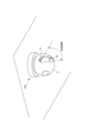
- FIG. 1 is a schematic diagram showing a configuration of a two-dimensional scanning sensor according to an embodiment of the present invention.
- FIG. 2 is a functional block diagram showing functions of the information processing apparatus according to the embodiment.
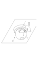
- FIG. 2 is a schematic diagram showing the state in which the two-dimensional scan sensor of the embodiment is installed on a ceiling.
- 1A and 1B are schematic diagrams illustrating problems caused by incorrect installation of a conventional two-dimensional scanning sensor.
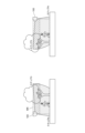
- FIG. 4 is a schematic diagram illustrating a first attitude of the sensor unit of the embodiment.
- FIG. 4 is a schematic diagram illustrating a second attitude of the sensor unit in the embodiment.
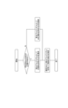
- 6 is a flowchart illustrating the operation of a process change unit according to the embodiment.
- 5A and 5B are schematic diagrams illustrating the operation of a process change unit according to the embodiment.
- 5A to 5C are schematic diagrams illustrating the operation of a second process change unit according to the embodiment.
- 5A to 5C are schematic diagrams illustrating the operation of a second process change unit according to the embodiment.
- 5A to 5C are schematic diagrams illustrating the operation of a third process change unit according to the embodiment.
- 5A to 5C are schematic diagrams illustrating the operation of a third process change unit according to the embodiment.
- 5A to 5C are schematic diagrams illustrating the operation of a third process change unit according to the embodiment.
- the two-dimensional scan sensor of this embodiment is provided indoors or outdoors and used for crime prevention and the like, and is used by being installed on, for example, a floor, a wall, or a ceiling.
- this two-dimensional scan sensor 100 includes a sensor unit 10 that scans light emitted from a light source along a two-dimensional plane, and an information processing device 20 that transmits and receives signals between the sensor unit 10.
- the sensor unit 10 includes a light source 11, a scanning mechanism 12 that scans the light emitted from the light source 11, and a photodetector 13 that receives the light reflected by an object located within a two-dimensional plane.
- the light source 11 emits light that is scanned over a security area set along a two-dimensional plane.
- the light source is a laser light source that emits laser light, and more specifically, emits pulses of laser light.
- the light source 11 is not limited to a laser light source, but may be a radiator that emits electromagnetic waves such as millimeter waves or microwaves.
- the scanning mechanism 12 scans the light emitted from the light source 11 along a two-dimensional plane. As shown in FIG. 1, the scanning mechanism 12 of this embodiment has a mirror 14 that reflects the light emitted from the light source 11, and rotates this mirror 14 around a predetermined axis.
- mirror 14 is disposed at an angle relative to the laser light emitted from light source 11, and by rotating mirror 14 around a predetermined rotation axis, the laser light is caused to scan along a predetermined plane.
- the scanning mechanism 12 may be one that rotates the light source 11 around a predetermined rotation axis to scan the light emitted from the light source 11 along a predetermined plane, and in this case the scanning mechanism 12 may not be equipped with a mirror 14.
- the scanning mechanism 12 may also be configured using a MEMS mirror.
- the scanning mechanism 12 is not limited to a mechanical scanning type, and may be an electronic scanning type, and specifically, a method of synthesizing signals from multiple receiving antennas by changing the phase using hardware or software can be mentioned.
- the photodetector 13 detects light reflected by an object existing in a two-dimensional plane, and outputs a light detection signal indicating the detection to the information processing device 20.
- the photodetector 13 in this embodiment receives laser light and is, for example, a photodiode such as an APD (avalanche photodiode).
- APD avalanche photodiode
- the photodetector 13 is not necessarily limited to this and may be changed as appropriate depending on, for example, the type of light source 11.
- the photodetector 13 may be configured to use multiple receiving antennas and detect the angle by detecting the phase difference between the antennas.
- the information processing device 20 is physically composed of a CPU, memory, etc., and functionally has the functions of a distance measuring unit 21 and an object detection unit 22, as shown in Figure 2, by the CPU and other peripheral devices working together in accordance with the program stored in the memory.
- the distance measuring unit 21 calculates the distance to an object based on the time it takes from when the light source 11 emits light to when it receives the light reflected by an object located on a two-dimensional plane.
- This distance measurement unit 21 is physically configured using a TOF (Time of Flight) circuit, etc., and is configured to calculate the distance to an object using a predetermined algorithm (hereinafter referred to as the calculation algorithm).
- TOF Time of Flight
- the distance measurement unit 21 measures the time from when the light source 11 emits a pulse of laser light to when that laser light is reflected and received by an object, and calculates the distance to the detected object by converting the measured time into distance.
- the object detection unit 22 detects objects located within a two-dimensional plane, and more specifically, obtains coordinates, which are position information of the detected object, from the angle of the laser light received by the photodetector 13.
- the sensor unit 10 configured in this manner is capable of scanning the light emitted from the light source 11 along a vertical plane by installing the two-dimensional scan sensor 100 in an appropriate position, and in this position, the distance measurement unit 21 is capable of calculating the height of the object from a reference plane using a predetermined calculation algorithm.
- the object detection unit 22 acquires the position information of the object and issues a notification (alert) that an object has been detected.
- the sensor unit 10 can scan light along a vertical plane over a range of, for example, 90 degrees.
- the sensor unit 10 can scan light emitted toward, for example, a floor surface toward a wall surface (side wall), or in other words, can scan light emitted vertically downward so that it heads horizontally.
- the angular range of light that can be scanned by the sensor unit 10 is not necessarily limited to 90 degrees, and may be changeable by a specified angle, for example, from 90 degrees in either direction, or may be capable of scanning over an angular range of 180 degrees or more.
- the distance measurement unit 21 calculates the height of the object from the floor surface based on the time it takes for the laser light to be reflected by the floor surface and received, and the time it takes for the laser light to be reflected by the object and received, according to a predetermined calculation algorithm.
- This problem is not limited to cases where the two-dimensional scanning sensor 100 is installed on a ceiling, but also occurs when it is installed on a wall. If the specified portion P is attached to the wall in the wrong direction, the conventional configuration will not be able to measure the height of the object correctly.
- the two-dimensional scanning sensor 100 of this embodiment has a high degree of freedom in installation, and it is easy for the specified portion P to be installed in the wrong orientation.
- the mounting posture of the sensor unit 10 in a usage mode in which the light emitted from the light source 11 is scanned along a vertical plane, can be changed between a first posture X in which the specified portion P faces a first direction, and a second posture Y in which the specified portion P faces a second direction perpendicular to the first direction.
- the mounting posture of the sensor unit 10 is not limited to only one of the first posture X and the second posture Y, but may be a posture between the first posture X and the second posture Y, or may be a posture in which the specified portion P faces in various directions.
- the mounting posture of the sensor unit 10 can be a first posture X ( Figure 5) in which the specified portion P faces downward (toward the floor), and a second posture Y ( Figure 6) in which the specified portion P faces to the side (toward the side wall).
- this two-dimensional scanning sensor 100 is configured so that the specific areas P can be oriented in different directions that are perpendicular to each other, even if the light scanning range is the same.
- the two-dimensional scanning sensor 100 of this embodiment further includes an orientation detection means 30 for detecting the orientation of a specific portion P of the sensor unit 10, as shown in FIG. 2, and the information processing device 20 described above further includes a function as a processing change unit 23 that changes the calculation algorithm of the distance measurement unit 21 based on the orientation information obtained by the orientation detection means 30.
- the orientation detection means 30 is for detecting whether the two-dimensional scan sensor 100 is in the correct installation position, and specifically, outputs the mounting angle of the two-dimensional scan sensor 100 as orientation information.
- the correct installation position here is a position in which the orientation of a specific part P, such as a particular screw, is in a predetermined correct orientation, and in this embodiment, it is a position in which the specific part P faces the floor surface (downward) (i.e., the first position X in Figure 5).
- the orientation of the specific part P is adopted as the mounting orientation of the two-dimensional scanning sensor 100, and if the two-dimensional scanning sensor 100 is installed in the correct mounting orientation, the orientation of the specific part P will be the correct orientation.
- the orientation detection means 30 is built into the casing C shown in FIG. 3 together with the sensor unit 10 and the like, and in this embodiment is configured using an acceleration sensor. However, the orientation detection means 30 may also be configured using, for example, a gyro sensor or a magnetic sensor.
- the processing modification unit 23 modifies the algorithm used by the distance measurement unit 21, i.e., the calculation algorithm for calculating the height of an object from the floor, based on the orientation information obtained by the orientation detection means 30.
- the process change unit 23 determines whether the orientation of the specified part P is normal or not by determining whether the mounting angle indicated by the orientation information is within a normal angle range, and based on the result of this determination, switches the calculation algorithm used by the distance measurement unit 21 to either normal or irregular orientation.
- the process modification unit 23 of this embodiment determines that the orientation of the specified part P is normal if the mounting angle indicated by the orientation information is vertically downward or within a specified angle range from vertically downward, and otherwise determines that the orientation of the specified part P is not normal (i.e., is an irregular orientation).
- a calculation algorithm for a normal orientation and a calculation algorithm for an irregular orientation are prepared as calculation algorithms used by the distance measurement unit 21, and these are stored in advance in the memory of the information processing device 20, for example.
- the process change unit 23 selects a calculation algorithm for the correct orientation for the distance measurement unit 21, and the distance measurement unit 21 calculates the height of the detected object from the floor surface using this calculation algorithm for the correct orientation.
- the process change unit 23 selects a calculation algorithm for the irregular orientation as the calculation algorithm for the distance measurement unit 21, and the distance measurement unit 21 calculates the height of the detected object from the floor surface using this calculation algorithm for the irregular orientation.
- the two-dimensional scanning sensor 100 of this embodiment is configured so that the orientation of the specific portion P can be different even if the light scanning range is the same, and these orientations can be perpendicular to each other.
- the correct installation position is one in which the specified part P faces downward, if the two-dimensional scanning sensor 100 is not in the correct installation position, there is a high probability that the specified part P faces to the side (horizontally).
- the calculation algorithm for the irregular orientation is an inverted version of, for example, the distance value array included in the calculation algorithm for the regular orientation.
- the distance measurement unit 21 of this embodiment is configured to calculate the distance from the reference surface to the object using multiple steps 1 to N that are set to divide the light scanning range of the sensor unit 10, as shown in FIG. 8.
- the calculation algorithm for the irregular orientation has the number of steps inverted from the calculation algorithm for the regular orientation. In other words, the sequence of steps 1 to N included in the calculation algorithm for the regular orientation is reversed from the sequence of steps 1 to N included in the calculation algorithm for the irregular orientation.
- the information processing device 20 of this embodiment has a function as a mask processing unit 24 that disables the detection of objects in a preset mask range MK within the light scanning range of the sensor unit 10.
- pre-set here means that it is set before the two-dimensional scanning sensor 100 is used, that it is set before the two-dimensional scanning sensor 100 is installed, or that it is set before the two-dimensional scanning sensor 100 is shipped.
- the method of setting the mask range MK may be such that, within the light scanning range of the sensor unit 10, a range preselected via the input means 40 is set as the mask range MK, or a range other than the preselected range may be set as the mask range MK.
- the mask range MK is set based on the number of steps described above. Specifically, a range corresponding to a number of preselected steps may be set as the mask range MK, or a range other than the range corresponding to a number of preselected steps may be set as the mask range MK.
- the mask processing unit 24 is configured to execute a masking operation that disables the detection of objects located in that mask range MK; specifically, it operates not to detect objects in that mask range MK, or not to report (issue an alert) even if an object located in that mask range MK is detected.
- the information processing device 20 further includes a second processing change unit 25 that changes the algorithm of the mask processing performed by the mask processing unit 24 (hereinafter, also referred to as the mask processing algorithm) based on the orientation information obtained by the orientation detection means 30 described above.
- a second processing change unit 25 that changes the algorithm of the mask processing performed by the mask processing unit 24 (hereinafter, also referred to as the mask processing algorithm) based on the orientation information obtained by the orientation detection means 30 described above.
- the second process change unit 25 determines whether the orientation of the specified part P is normal or not by determining whether the mounting angle indicated by the orientation information is within a normal angle range, and switches the mask processing algorithm used by the mask processing unit 24 to either the normal orientation or the non-normal orientation based on the result of the determination.
- the second process modification unit 25 selects a mask processing algorithm for the normal orientation for the mask processing unit 24, and the mask processing unit 24 executes the above-mentioned mask operation using this mask processing algorithm for the normal orientation.
- the second process modification unit 25 selects a mask processing algorithm for the mask processing unit 24 that is for an irregular orientation, and the mask processing unit 24 executes the above-mentioned mask operation using this calculation algorithm for the irregular orientation.
- the above-mentioned calculation algorithm is one in which the number of steps for the normal and non-normal orientations are swapped
- the mask processing algorithm is also one in which the number of steps for the normal and non-normal orientations are swapped.
- the operation by the process modification unit 23 and the operation by the second process modification unit 25 are executed simultaneously, and when a calculation algorithm for a normal orientation is selected, a mask processing algorithm for a normal orientation is also selected, and when a calculation algorithm for an irregular orientation is selected, a mask processing algorithm for an irregular orientation is also selected.
- the operation by the process change unit 23 and the operation by the second change processing unit do not necessarily need to be executed simultaneously, and the contents and timing of their operations may be independent of each other.
- the two-dimensional scanning sensor 100 of this embodiment is provided with an imaging means 50 that captures part or all of the light scanning range of the sensor unit 10, and the information processing device 20 further functions as an image display unit 26 that displays the image obtained by the imaging means 50.
- the imaging means 50 is housed in the casing C together with the sensor unit 10, and outputs still images or videos as imaging data.
- the image display unit 26 displays the imaging data, which is a still image or video, acquired by the imaging means 50 on, for example, a display 60.
- This image display unit 26 displays imaging data including the time of detection when the object detection unit 22 notifies (issues an alert) that an object has been detected. Specifically, it obtains the coordinates of the object detected by the object detection unit 22 and displays a marker M indicating the position of the object together with an actual image Z in which the object appears (see FIG. 11c).
- the image display unit 26 is configured to display the above-mentioned marker M superimposed on the real image Z in which the detected object is captured, and the real image Z and the marker M are displayed simultaneously on the same screen.
- the information processing device 20 further includes a function as a third process change unit 27 that changes the display content of the image displayed by the image display unit 26, as shown in FIG. 2.
- a more specific embodiment of the third process change unit 27 may be one in which the display content of the displayed image is changed based on the amount of misalignment between the sensor unit 10 and the imaging means 50 input via the input means 70, as shown in FIG. 2, or one in which the display content of the displayed image is changed based on the amount of misalignment between the sensor unit 10 and the imaging means 50 detected using an acceleration sensor or the like other than the orientation detection means 30 described above, although this is not shown.
- This third process modification unit 27 corrects the position of an object in the real image Z or the position of a marker M indicating the position of an object in the image, and specifically modifies the position of the real image Z on the display 60 or the position of the marker M on the display 60.
- the third process modification unit 27 corrects the position of the object or marker M shown in the actual image Z so that the object and marker M overlap (Fig. 11c).
- the third process change unit 27 may change the display mode of the scanning range symbol S based on the orientation information obtained by the orientation detection means 30.
- Specific examples of implementation include a case where the light from the sensor unit 10 is scanned horizontally (Figure 12a), a case where the light from the sensor unit 10 is scanned vertically and the two-dimensional scan sensor 100 is attached to, for example, the floor surface and facing upwards ( Figure 12b), and a case where the light from the sensor unit 10 is scanned vertically and the two-dimensional scan sensor 100 is attached to, for example, the ceiling and facing downwards (Figure 12c), in which the scanning range symbol S is displayed in different display modes.
- the third process modification unit 27 may rotate and display the still image or video, which is the imaging data, based on the orientation information obtained by the orientation detection means 30.
- the third process change unit 27 sets the display mode of the still image or video by the image display unit 26 to landscape display (Fig. 13a), and when the light from the sensor unit 10 is scanned vertically, the third process change unit 27 sets the display mode of the still image or video by the image display unit 26 to portrait display (Figs. 13b, c).
- the third process change unit 27 may set the display mode of the still image or video by the image display unit 26 to be upside down when the two-dimensional scanning sensor 100 faces forward ( Figure 13b) and when it faces backward (Figure 13c).
- the sensor unit 10 can scan the light emitted from the light source 11 along a vertical plane, and the distance measurement unit 21 can calculate the height of the object from the reference plane, so the height of the object can be measured correctly regardless of the orientation in which it is attached.
- the mounting posture of the sensor unit 10 can be changed between a first posture X in which the specified portion P faces a first direction, and a second posture Y in which the specified portion P faces a second direction perpendicular to the first direction, thereby improving the degree of freedom in installation while preventing rework due to incorrect installation.
- the process change unit 23 selectively switches the calculation algorithm used by the distance measurement unit 21 between a normal orientation and an abnormal orientation depending on whether the orientation of the specified part P indicated by the orientation information is normal or not, thereby simplifying the process.
- the sensor unit 10 is provided with a mask processing unit 24 that disables detection of objects in a preset mask range within the light scanning range, and a second processing change unit 25 that changes the algorithm of the mask processing by the mask processing unit 24 based on orientation information.
- a mask processing unit 24 that disables detection of objects in a preset mask range within the light scanning range
- a second processing change unit 25 that changes the algorithm of the mask processing by the mask processing unit 24 based on orientation information.
- the device is equipped with an imaging means 50 that captures an image of part or all of the light scanning range of the sensor unit 10, an image display unit 26 that displays the image obtained by the imaging means 50, and a third process modification unit 27 that modifies the display content of the image displayed by the image display unit 26 based on orientation information, so that while it is equipped with an image display function for improving usability, this image display function can be operated correctly regardless of the orientation in which the two-dimensional scanning sensor 100 is attached.
- the third process modification unit 27 is configured to correct the position of an object in the image or the position of a marker M indicating the position of an object in the image based on the orientation information obtained by the orientation detection means 30, thereby improving the visibility of the image.
- the third process change unit 27 changes the display mode of the scanning range symbol S and the display orientation of the still image or video captured by the imaging means 50 based on the orientation information obtained by the orientation detection means 30, thereby further improving visibility.
- the distance measuring unit 21 calculates the height of the object from the floor, but it may also calculate the distance from the side wall or ceiling of the object.
- the floor is described as the reference plane, but various wall surfaces such as the side wall and floor may be used as the reference plane.
- the calculation algorithm for the non-normal orientation was obtained by reversing the number of steps of the calculation algorithm for the normal orientation, but it may also be obtained by modifying the algorithm for the normal orientation using, for example, the mounting angle obtained by the orientation detection means 30 as a parameter.
- An example of such a calculation algorithm for an irregular orientation may be one in which only the number of valid steps is enabled out of the number of steps included in the calculation algorithm for a regular orientation, based on, for example, the mounting angle.
- the present invention makes it possible to measure distances regardless of the installation direction, preventing rework due to incorrect installation.
- REFERENCE SIGNS LIST 100 Two-dimensional scan sensor 10
- Sensor unit 11 Light source 12
- Scanning mechanism 13 ... Photodetector 14
- Mirror 20 Information processing device 21
- Distance measuring unit 22 ...
- Object detection unit 23 Processing change unit 24
- Mask processing unit 25 ...
- Second processing change unit 26 ...
- Image display unit 27 ...
- Third processing change unit 30 ...
- Orientation detection means P P... Predetermined portion X... First attitude Y... Second attitude M... Marker
Landscapes
- Engineering & Computer Science (AREA)
- Physics & Mathematics (AREA)
- Radar, Positioning & Navigation (AREA)
- Remote Sensing (AREA)
- Computer Networks & Wireless Communication (AREA)
- General Physics & Mathematics (AREA)
- Electromagnetism (AREA)
- Optical Radar Systems And Details Thereof (AREA)
Priority Applications (3)
| Application Number | Priority Date | Filing Date | Title |
|---|---|---|---|
| PCT/JP2022/047734 WO2024134900A1 (ja) | 2022-12-23 | 2022-12-23 | 二次元スキャンセンサ |
| JP2024565562A JPWO2024134900A1 (https=) | 2022-12-23 | 2022-12-23 | |
| EP22969279.3A EP4641257A1 (en) | 2022-12-23 | 2022-12-23 | Two-dimensional scan sensor |
Applications Claiming Priority (1)
| Application Number | Priority Date | Filing Date | Title |
|---|---|---|---|
| PCT/JP2022/047734 WO2024134900A1 (ja) | 2022-12-23 | 2022-12-23 | 二次元スキャンセンサ |
Publications (1)
| Publication Number | Publication Date |
|---|---|
| WO2024134900A1 true WO2024134900A1 (ja) | 2024-06-27 |
Family
ID=91587952
Family Applications (1)
| Application Number | Title | Priority Date | Filing Date |
|---|---|---|---|
| PCT/JP2022/047734 Ceased WO2024134900A1 (ja) | 2022-12-23 | 2022-12-23 | 二次元スキャンセンサ |
Country Status (3)
| Country | Link |
|---|---|
| EP (1) | EP4641257A1 (https=) |
| JP (1) | JPWO2024134900A1 (https=) |
| WO (1) | WO2024134900A1 (https=) |
Cited By (2)
| Publication number | Priority date | Publication date | Assignee | Title |
|---|---|---|---|---|
| WO2026004163A1 (ja) * | 2024-06-24 | 2026-01-02 | 三菱電機株式会社 | センサ |
| JP7855145B1 (ja) | 2024-06-24 | 2026-05-07 | 三菱電機株式会社 | センサ |
Citations (5)
| Publication number | Priority date | Publication date | Assignee | Title |
|---|---|---|---|---|
| JP6155386B1 (ja) | 2015-11-16 | 2017-06-28 | オプテックス株式会社 | レーザースキャンセンサ |
| JP2019100985A (ja) * | 2017-12-07 | 2019-06-24 | コニカミノルタ株式会社 | 3次元情報取得システム |
| WO2020105527A1 (ja) * | 2018-11-20 | 2020-05-28 | コニカミノルタ株式会社 | 画像解析装置、画像解析システム、および制御プログラム |
| US20200241538A1 (en) * | 2019-01-24 | 2020-07-30 | Sick Ag | Method of monitoring a protected zone |
| JP2021185366A (ja) * | 2018-03-29 | 2021-12-09 | ヤンマーパワーテクノロジー株式会社 | 障害物検知システム |
Family Cites Families (1)
| Publication number | Priority date | Publication date | Assignee | Title |
|---|---|---|---|---|
| JP7097709B2 (ja) * | 2018-02-01 | 2022-07-08 | 株式会社トプコン | 測量システム |
-
2022
- 2022-12-23 EP EP22969279.3A patent/EP4641257A1/en active Pending
- 2022-12-23 JP JP2024565562A patent/JPWO2024134900A1/ja active Pending
- 2022-12-23 WO PCT/JP2022/047734 patent/WO2024134900A1/ja not_active Ceased
Patent Citations (5)
| Publication number | Priority date | Publication date | Assignee | Title |
|---|---|---|---|---|
| JP6155386B1 (ja) | 2015-11-16 | 2017-06-28 | オプテックス株式会社 | レーザースキャンセンサ |
| JP2019100985A (ja) * | 2017-12-07 | 2019-06-24 | コニカミノルタ株式会社 | 3次元情報取得システム |
| JP2021185366A (ja) * | 2018-03-29 | 2021-12-09 | ヤンマーパワーテクノロジー株式会社 | 障害物検知システム |
| WO2020105527A1 (ja) * | 2018-11-20 | 2020-05-28 | コニカミノルタ株式会社 | 画像解析装置、画像解析システム、および制御プログラム |
| US20200241538A1 (en) * | 2019-01-24 | 2020-07-30 | Sick Ag | Method of monitoring a protected zone |
Non-Patent Citations (1)
| Title |
|---|
| See also references of EP4641257A1 |
Cited By (2)
| Publication number | Priority date | Publication date | Assignee | Title |
|---|---|---|---|---|
| WO2026004163A1 (ja) * | 2024-06-24 | 2026-01-02 | 三菱電機株式会社 | センサ |
| JP7855145B1 (ja) | 2024-06-24 | 2026-05-07 | 三菱電機株式会社 | センサ |
Also Published As
| Publication number | Publication date |
|---|---|
| EP4641257A1 (en) | 2025-10-29 |
| JPWO2024134900A1 (https=) | 2024-06-27 |
Similar Documents
| Publication | Publication Date | Title |
|---|---|---|
| US8384914B2 (en) | Device for optically scanning and measuring an environment | |
| EP3191888B1 (en) | Scanning laser planarity detection | |
| US11335182B2 (en) | Methods and systems for detecting intrusions in a monitored volume | |
| CN102445688B (zh) | 组合的飞行时间和图像传感器系统 | |
| JP3950837B2 (ja) | プロジェクタ並びにプロジェクタを使用した電子黒板システム及び指示位置取得方法 | |
| US20160245918A1 (en) | Directed registration of three-dimensional scan measurements using a sensor unit | |
| US10436901B2 (en) | Optoelectronic sensor and method for detecting objects | |
| JP5518321B2 (ja) | レーザレーダ用設置位置検証装置、レーザレーダ用設置位置の検証方法及びレーザレーダ用設置位置検証装置用プログラム | |
| RU2669200C2 (ru) | Устройство обнаружения препятствий при помощи пересекающихся плоскостей и способ обнаружения с применением такого устройства | |
| JP2019100985A (ja) | 3次元情報取得システム | |
| JP2019144210A (ja) | 物体検出システム | |
| EP3723047A1 (en) | Localization and projection in buildings based on a reference system | |
| WO2024134900A1 (ja) | 二次元スキャンセンサ | |
| WO2016195822A1 (en) | Calibration for touch detection on projected display surfaces | |
| US11776153B2 (en) | Method, system and apparatus for mobile dimensioning | |
| US11614528B2 (en) | Setting method of monitoring system and monitoring system | |
| JP2007013709A (ja) | 設定装置 | |
| JP4754283B2 (ja) | 監視システム及び設定装置 | |
| EP3795946B1 (en) | Three-dimensional survey apparatus, three-dimensional survey method, and three-dimensional survey program | |
| US11100674B2 (en) | Information processing apparatus, information processing system, and non-transitory computer readable medium | |
| US12579753B2 (en) | Phased capture assessment and feedback for mobile dimensioning | |
| JP7757841B2 (ja) | センサシステムおよびその制御方法 | |
| WO2019093371A1 (ja) | 物体検出システム及び物体検出プログラム | |
| US20250182316A1 (en) | Information processing device and information processing method | |
| EP4258011A1 (en) | Image-based scan pre-registration |
Legal Events
| Date | Code | Title | Description |
|---|---|---|---|
| 121 | Ep: the epo has been informed by wipo that ep was designated in this application |
Ref document number: 22969279 Country of ref document: EP Kind code of ref document: A1 |
|
| WWE | Wipo information: entry into national phase |
Ref document number: 2024565562 Country of ref document: JP |
|
| WWE | Wipo information: entry into national phase |
Ref document number: 2022969279 Country of ref document: EP |
|
| NENP | Non-entry into the national phase |
Ref country code: DE |
|
| ENP | Entry into the national phase |
Ref document number: 2022969279 Country of ref document: EP Effective date: 20250723 |
|
| ENP | Entry into the national phase |
Ref document number: 2022969279 Country of ref document: EP Effective date: 20250723 |
|
| ENP | Entry into the national phase |
Ref document number: 2022969279 Country of ref document: EP Effective date: 20250723 |
|
| WWP | Wipo information: published in national office |
Ref document number: 2022969279 Country of ref document: EP |