WO2024128264A1 - 映像表示装置 - Google Patents
映像表示装置 Download PDFInfo
- Publication number
- WO2024128264A1 WO2024128264A1 PCT/JP2023/044690 JP2023044690W WO2024128264A1 WO 2024128264 A1 WO2024128264 A1 WO 2024128264A1 JP 2023044690 W JP2023044690 W JP 2023044690W WO 2024128264 A1 WO2024128264 A1 WO 2024128264A1
- Authority
- WO
- WIPO (PCT)
- Prior art keywords
- eye
- pixels
- image
- display
- range
- Prior art date
- Legal status (The legal status is an assumption and is not a legal conclusion. Google has not performed a legal analysis and makes no representation as to the accuracy of the status listed.)
- Ceased
Links
Images









Classifications
-
- H—ELECTRICITY
- H04—ELECTRIC COMMUNICATION TECHNIQUE
- H04N—PICTORIAL COMMUNICATION, e.g. TELEVISION
- H04N13/00—Stereoscopic video systems; Multi-view video systems; Details thereof
- H04N13/10—Processing, recording or transmission of stereoscopic or multi-view image signals
- H04N13/106—Processing image signals
- H04N13/122—Improving the three-dimensional [3D] impression of stereoscopic images by modifying image signal contents, e.g. by filtering or adding monoscopic depth cues
- H04N13/125—Improving the three-dimensional [3D] impression of stereoscopic images by modifying image signal contents, e.g. by filtering or adding monoscopic depth cues for crosstalk reduction
-
- H—ELECTRICITY
- H04—ELECTRIC COMMUNICATION TECHNIQUE
- H04N—PICTORIAL COMMUNICATION, e.g. TELEVISION
- H04N13/00—Stereoscopic video systems; Multi-view video systems; Details thereof
- H04N13/30—Image reproducers
- H04N13/302—Image reproducers for viewing without the aid of special glasses, i.e. using autostereoscopic displays
- H04N13/317—Image reproducers for viewing without the aid of special glasses, i.e. using autostereoscopic displays using slanted parallax optics
-
- H—ELECTRICITY
- H04—ELECTRIC COMMUNICATION TECHNIQUE
- H04N—PICTORIAL COMMUNICATION, e.g. TELEVISION
- H04N13/00—Stereoscopic video systems; Multi-view video systems; Details thereof
- H04N13/30—Image reproducers
- H04N13/366—Image reproducers using viewer tracking
Definitions
- the present invention relates to a video display device.
- This application claims priority based on Japanese Patent Application No. 2022-198604, filed on December 13, 2022, the contents of which are incorporated herein by reference.
- the above-mentioned three-dimensional display device can provide appropriate stereoscopic vision even when the observer moves, if the interocular distance of the observer is equal to the average human interocular distance and both of the observer's eyes are parallel to the display surface of the display. However, for observers who do not meet these conditions, it may not be possible to provide appropriate stereoscopic vision. Furthermore, the above-mentioned multi-viewpoint display may not be able to provide an appropriate view to each of the multiple observers if the distance between the multiple observers is not equal to a specified distance, or if the multiple observers are not parallel to the display surface.
- the present invention was made in consideration of these circumstances, and its purpose is to provide an image display device that can improve the visibility of an image even when the observer's eyes are not positioned in a specified position.
- One aspect of the present invention includes a display having a display surface including a plurality of pixels, and displaying on the display surface a first image to be viewed by a first eye and a second image to be viewed by a second eye, an optical element that limits a first eye position, which is the first eye position at which the first image is viewable, and a second eye position, which is the second eye position at which the second image is viewable, a position acquisition unit that acquires the first eye position and the second eye position, and a display unit that uses the first eye position and the second eye position independently to determine a first image display pixel range for displaying the first image based on the first eye position, and determines the second image based on the second eye position.
- a display control unit that controls the display so that the first image is assigned to pixels included in the first image display pixel range and the second image is assigned to pixels included in the second image display pixel range, and the display control unit determines a binocular overlap range that can be seen by both the first eye and the second eye in the first image display pixel range and the second image display pixel range, and when it is determined that a binocular overlap range exists, controls the display to reduce the luminance of one or more pixels included in the binocular overlap range.
- the present invention has the effect of improving the visibility of an image even when the observer's eyes are not positioned in a specified position.
- FIG. 1 is a diagram illustrating an example of a stereoscopic display device according to an embodiment.
- 10 is a flowchart illustrating an example of a procedure at a design stage of a control method for a stereoscopic display device according to an embodiment.
- FIG. 11 is an explanatory diagram of a barrier end surface overlapping pixel range according to an embodiment.
- FIG. 11 is an explanatory diagram of an example of a method for determining a brightness reduction method according to an embodiment.
- 10 is a flowchart illustrating an example of a procedure of an operation stage of a control method for a stereoscopic display device according to an embodiment.
- FIG. 11 is an explanatory diagram for explaining a luminance uniformization process according to an embodiment.
- FIG. 11 is an explanatory diagram for explaining a luminance uniformization process according to an embodiment.
- FIG. 13 is a diagram illustrating an example of a stereoscopic display device according to a modified example of the embodiment.
- 10A and 10B are explanatory diagrams for explaining an example of a control method for a stereoscopic display device according to a modified example of the embodiment.
- 10A and 10B are explanatory diagrams for explaining an example of a control method for a stereoscopic display device according to a modified example of the embodiment.
- 10A and 10B are explanatory diagrams for explaining an example of a control method for a stereoscopic display device according to a modified example of the embodiment.
- 10A and 10B are explanatory diagrams for explaining an example of a control method for a stereoscopic display device according to a modified example of the embodiment.
- Fig. 1 is a diagram showing an example of a stereoscopic display device according to an embodiment.
- the stereoscopic display device 100 includes a display 101, an optical element 102, a display control unit 103, a storage unit 104, and a position acquisition unit 105.
- the X-axis, Y-axis, and Z-axis shown in Fig. 1 are used as appropriate.
- the display 101 has a display surface including a plurality of pixels arranged along a first direction and a second direction.
- the first direction is, for example, the X direction shown in FIG. 1.
- the second direction is a direction intersecting the first direction, for example, the Y direction shown in FIG. 1.
- the display 101 is parallel to the XY plane, and displays a pair of a right-eye image MR and a left-eye image ML on a plane perpendicular to the Z axis for every n (n is a positive integer equal to or greater than 2m, and m is a positive integer) pixels on the display surface.
- Each of the right-eye image MR and the left-eye image ML is composed of a size of m pixels.
- the right-eye image MR is an image to be viewed by the right eye ER of the observer P.
- the left-eye image ML is an image to be viewed by the left eye EL of the observer P.
- the pair of the right-eye image MR and the left-eye image ML is a parallax image.
- the pair of the right-eye image MR and the left-eye image ML is correctly viewed by the right eye ER and the left eye EL of the observer P, thereby providing the observer P with normal stereoscopic vision.
- the arrangement of pixels on the display surface of the display 101 shown in FIG. 1 is for convenience of explanation.
- the display 101 is, as an example, a self-luminous display.
- the pixels arranged on the display surface of the display 101 correspond to any one of the colors R (Red), G (Green), and (Blue).
- Three pixels R, G, and B may be grouped together to form one pixel.
- the pixel corresponding to any one of the colors R, G, and B is also referred to as a subpixel. Therefore, three subpixels R, G, and B may be grouped together to form one pixel.
- the first direction is, for example, the direction in which the multiple subpixels that form one pixel are lined up.
- the second direction is, for example, the direction in which subpixels corresponding to the same color are lined up.
- the optical element 102 is, for example, a parallax barrier having a light-shielding region and a transparent region.
- the optical element 102 limits the position of the right eye ER and the position of the left eye EL by the light-shielding region and the transparent region.
- the optical element 102 is, for example, a parallax barrier having linear slits inclined at a predetermined angle (tilt angle) with respect to the X-axis and the Y-axis.
- a parallax barrier having one opening for n pixels is used as an example of the optical element 102.
- the optical element 102 limits the positions of the right eye ER and the left eye EL at which the right eye image MR and the left eye image ML can be viewed, respectively. Also, as shown in FIG. 1, in order for the right eye ER and the left eye EL of the observer P to observe normal stereoscopic vision on the entire screen, the observer P needs to observe from a position that is an optimal observation distance OVD away from the optical element 102.
- the opening is an example of a transparent region. Also, the region other than the opening in the parallax barrier is an example of a light-shielding region.
- the detection device 3 detects the positions of the right eye ER and the left eye EL of the observer P and outputs the positions to the stereoscopic display device 100.
- the detection device 3 detects the positions of the right eye ER and the left eye EL individually.
- the detection device 3 includes a sensor such as a camera.
- the detection device 3 includes a camera and detects the positions of the right eye ER and the left eye EL from an image of the face of the observer P captured by the camera.
- the detection device 3 outputs the three-dimensional coordinates of the detected positions of the right eye ER and the left eye EL of the observer P to the stereoscopic display device 100.
- the detection device 3 may be included in the stereoscopic display device 100, or may be a device separate from the stereoscopic display device 100.
- the detection device 3 is an example of a viewpoint detection unit that detects the first eye position and the second eye position individually.
- the position acquisition unit 105 acquires the positions of the right eye ER and the left eye EL of the observer P. Specifically, the position acquisition unit 105 acquires the three-dimensional coordinates of the position of the right eye ER and the position of the left eye EL of the observer P input from the detection device 3 to the stereoscopic display device 100. The position acquisition unit 105 acquires the positions of the right eye ER and the left eye EL detected individually by the detection device 3.
- the display control unit 103 determines the right-eye image display pixel range of the right-eye image MR to be assigned to the position of the right eye ER of the observer P and the left-eye image display pixel range of the left-eye image ML to be assigned to the position of the left eye EL, and controls the display 101 to display the right-eye image MR in the right-eye image display pixel range and the left-eye image ML in the left-eye image display pixel range.
- assigning an image to the position of the eye of observer P means assigning the image to pixels included in the range viewed by that eye on the display surface of display 101.
- Display control unit 103 uses the positions of right eye ER and left eye EL independently to determine a right-eye image display pixel range for displaying right-eye image MR based on the position of right eye ER, and determines a left-eye image display pixel range for displaying left-eye image ML based on the position of left eye EL, and controls display 101 so that the right-eye image MR is assigned to pixels included in the right-eye image display pixel range, and the left-eye image ML is assigned to pixels included in the left-eye image display pixel range.
- assigning an image to a pixel means assigning a luminance value based on the image to the pixel.
- the display control unit 103 also determines a left-right overlap range that can be seen by both the right eye ER and left eye EL of the observer P in the right-eye image display pixel range and the left-eye image display pixel range, and if the determination indicates that there is a left-right overlap range, controls the display 101 to reduce the luminance of one or more pixels included in the left-right overlap range.
- a method of reducing luminance is to display black.
- the right eye ER is an example of the first eye
- the left eye EL is an example of the second eye.
- the left-right overlap range is also an example of a both-eye overlap range.
- the storage unit 104 stores various types of data.
- the storage unit 104 is accessed by the display control unit 103.
- the display control unit 103 is realized, for example, by a display control program stored in a storage medium being read out and executed by a CPU (Central Processing Unit) or the like.
- the display control unit 103 may be realized by hardware including circuitry such as an LSI (Large Scale Integration), an ASIC (Application Specific Integrated Circuit), an FPGA (Field-Programmable Gate Array), or a GPU (Graphics Processing Unit).
- the display control unit 103 may be realized by a combination of software and hardware. Furthermore, these pieces of hardware may be integrated into one, or may be divided into multiple pieces.
- the storage unit 104 may also be configured with non-volatile memory such as a hard disk device, a magneto-optical disk device, or a flash memory, a read-only recording medium such as a CD-ROM, or volatile memory such as a dynamic random access memory (DRAM), or a combination of these.
- non-volatile memory such as a hard disk device, a magneto-optical disk device, or a flash memory
- a read-only recording medium such as a CD-ROM
- volatile memory such as a dynamic random access memory (DRAM), or a combination of these.
- the control method for the stereoscopic display device 100 has a design stage and an operation stage.
- the design stage is carried out when the stereoscopic display device 100 is designed.
- the operation stage is carried out when the observer P uses the stereoscopic display device 100.
- FIG. 2 is a flowchart showing an example of the procedure of the design stage of the control method for the stereoscopic display device according to the present embodiment.
- Step S101 The number of pixels m, which is the size of the right-eye image MR and the left-eye image ML, is determined. A method for determining the number of pixels m will be described.
- On the display surface of the display 101 there are areas (pixel areas) corresponding to n pixels each of which is observed at the center of the X-axis direction of the opening of the optical element 102 as viewed from the observer P at the optimal observation distance OVD, and these areas are present in a continuous manner at equal intervals in the X-axis direction.
- "m ⁇ n/2" holds, and the width A of the m pixel areas in the X-axis direction is "A ⁇ E" with respect to "average interocular distance E of a person".
- the quotient obtained by dividing "average interocular distance E of a person" by "width of one pixel area in the X-axis direction" in the design of the display 101 can be obtained as the number of pixels m.
- the relationship "m ⁇ n/2" indicates that it is possible to have pixels among the n pixels that are not seen at all by the observer P at the optimal observation distance OVD.
- the 0th to 1st pixels are shown as the pixels that are not seen at all.
- the pixel region on the display surface of the display 101 may be simply referred to as a pixel.
- the pixel refers to the sub-pixel described above.
- Step S102 The number of pixels (one-eye pixel number) q in the range of pixels observed by one eye (one-eye pixel range) is determined from the designed aperture ratio of the optical element 102.
- the aperture ratio of the parallax barrier as the optical element 102 is defined by the formula "(m-k)/n, k ⁇ m".
- k is the number of pixels out of m pixels that cannot be seen by the observer P at the optimal observation distance OVD.
- “aperture ratio 50%”.
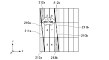
- FIG. 3 is an explanatory diagram of the barrier end surface overlapping pixel range according to this embodiment.
- FIG. 3 shows pixels 200 in the barrier end surface overlapping pixel range that overlap with the barrier end surface 210 of the parallax barrier as the optical element 102.
- the pixels 200 in the barrier end surface overlapping pixel range are pixels that can be viewed by both the right eye ER and the left eye EL of the observer P.
- the barrier end surface overlapping pixel range may be viewed by both the right eye and the left eye, which may cause crosstalk.
- the barrier end surface overlapping pixel range is a range in which it is preferable to perform the luminance reduction process described later.
- ⁇ is the inclination angle of the parallax barrier.
- the inclination angle ⁇ of the parallax barrier is an angle equal to or greater than 0° and less than 90°.
- the length of the pixel on the display surface of the display 101 in the X direction is Hp
- the length of the pixel on the display surface in the Y direction is Vp
- a and b are natural numbers.
- the display control unit 103 determines the range (in this embodiment, the barrier end surface overlap pixel range) that is the end (in this embodiment, the barrier end surface 210) of the range observed through the optical element 102 from the first eye position (in this embodiment, the position of the right eye ER) and that is the end (in this embodiment, the barrier end surface 210) of the range observed through the optical element 102 from the second eye position (in this embodiment, the position of the left eye EL) as the both-eye overlap range (in this embodiment, the left-right overlap range).
- the range in this embodiment, the barrier end surface overlap pixel range
- Step S104 The brightness reduction method is determined, and the determined brightness reduction method is stored in the storage unit 104.
- the method of determining the brightness reduction method will be described. Among the number r of pixels in the barrier end surface overlapping pixel range, the number p of pixels that may be subjected to the brightness reduction process is determined.
- the brightness reduction process is, for example, black display.
- FIG. 4 is an explanatory diagram of an example of a method of determining the brightness reduction method.
- the barrier opening is inside between the barrier end surface 210a and the barrier end surface 210b of the parallax barrier as the optical element 102.
- FIG. 4 is an explanatory diagram of an example of a method of determining the brightness reduction method.
- the barrier opening is inside between the barrier end surface 210a and the barrier end surface 210b of the parallax barrier as the optical element 102.
- pixels 211a, 212a, and 213a in the barrier end surface overlapping pixel range on the barrier end surface 210a, and pixels 211b, 212b, and 213b in the barrier end surface overlapping pixel range on the barrier end surface 210b are shown.
- r 3.
- p ⁇ r.
- p may be an even number
- p may be an odd number
- p may be an odd number.
- p may be two, and conversely, when r is an odd number, p may be one.
- a right-eye evaluation pixel range of evaluation pixels "q+p" and a left-eye evaluation pixel range of evaluation pixels "q+p" are used.
- the positions of the right eye ER and the left eye EL of observer P are acquired, and a right-eye evaluation pixel range of evaluation pixels "q+p" to be assigned to the acquired right-eye ER position and a left-eye evaluation pixel range of evaluation pixels "q+p" to be assigned to the acquired left-eye EL position are determined, and the range where the determined right-eye evaluation pixel range and left-eye evaluation pixel range overlap (evaluation overlap range) is determined.
- a luminance reduction method for the evaluation overlap range where the right-eye evaluation pixel range and left-eye evaluation pixel range overlap is determined, and the determined luminance reduction method is stored in the storage unit 104.
- the luminance of the evaluation overlap range is reduced.
- a predetermined first threshold e.g. 2p
- the luminance of at least one pixel (barrier end surface luminance reduction pixel) among the p pixels in the barrier end surface overlap pixel range is reduced, the luminance of pixels that are separated from the at least one barrier end surface luminance reduction pixel by the one-eye pixel number q is also reduced as a moiré prevention process.
- the number of pixels in the evaluation overlap range exceeds a predetermined second threshold (e.g., 2p) for one eye, the luminance of the excess number of pixels is only reduced, and the moiré prevention process is not performed.
- a predetermined second threshold e.g. 2p
- An example of a method for reducing the luminance is black display.
- the above-mentioned moire prevention process needs to be performed only when it is determined that moire will occur due to the design of the stereoscopic display device 100.
- the number of pixels whose luminance is reduced by displaying black or the like on the display surface of display 101 increases due to the above-mentioned luminance reduction method, uneven brightness on the display surface of display 101 becomes noticeable, or the display surface of display 101 becomes dark overall.
- the number of pixels on which the luminance reduction process is performed within the display surface of display 101 may differ partially depending on the state of observer P. This may cause uneven brightness on the display surface of display 101 to become noticeable.
- a setting is made to execute a luminance uniformization process that uniformizes the luminance across the entire display surface of display 101.
- the above-mentioned brightness reduction method is determined for all possible cases in the design of the stereoscopic display device 100 and stored in the storage unit 104.
- FIG. 5 is a flowchart showing an example of the procedure of the operation stage of the control method for the stereoscopic display device according to the present embodiment.
- Step S201 The position acquisition unit 105 acquires the three-dimensional coordinates of the position of the right eye ER and the three-dimensional coordinates of the position of the left eye EL of the observer P input from the detection device 3 to the stereoscopic display device 100.
- Step S202 The display control unit 103 determines a right-eye evaluation pixel range of "q+p" evaluation pixels to be assigned to the position of the right eye ER and a left-eye evaluation pixel range of "q+p" evaluation pixels to be assigned to the position of the left eye EL based on the three-dimensional coordinates of the position of the right eye ER and the three-dimensional coordinates of the position of the left eye EL of the observer P acquired by the position acquisition unit 105.
- the display control unit 103 determines the right-eye evaluation pixel range and the left-eye evaluation pixel range using the three-dimensional coordinates of the position of the right eye ER and the three-dimensional coordinates of the position of the left eye EL of the observer P independently.
- Step S203 The display control unit 103 determines the range where the right eye evaluation pixel range and the left eye evaluation pixel range determined in step S202 overlap (evaluation overlap range).
- the evaluation overlap range changes depending on the actual interocular distance E' of the observer P and the observation state of the observer P (such as the posture of the observer P, such as the tilt of the head or upper body). If the result of the determination in step S203 is that there is an evaluation overlap range (step S203, YES), the process proceeds to step S205. On the other hand, if there is no evaluation overlap range (step S203, NO), the process proceeds to step S204.
- Step S204 If there is no evaluation overlap range as determined in step S203, the display control unit 103 controls the display 101 to display the right-eye image MR by setting the one-eye pixel range (number of pixels "q") including the center pixel of the right-eye evaluation pixel range (number of pixels "q+p") as the right-eye image display pixel range, and to display the left-eye image ML by setting the one-eye pixel range (number of pixels "q") including the center pixel of the left-eye evaluation pixel range (number of pixels "q+p") as the left-eye image display pixel range. Then, proceed to step S207. In this case, the brightness reduction process is not executed.
- the display control unit 103 determines whether or not there is a both-eye overlap range (in this embodiment, the evaluation overlap range), and if it determines that there is no both-eye overlap range, it determines the area that is viewed from the first eye position (in this embodiment, the position of the right eye ER) and not viewed from the second eye position (in this embodiment, the position of the left eye EL) as the first image display pixel range (in this embodiment, the right eye image display pixel range), determines the area that is viewed from the second eye position and not viewed from the first eye position as the second image display pixel range (in this embodiment, the left eye image display pixel range), and controls the display 101 so that the first image (in this embodiment, the right eye image MR) is assigned to the pixels included in the first image display pixel range, and the second image (in this embodiment, the left eye image ML) is assigned to the pixels included in the second image display pixel range.
- the first image in this embodiment, the right eye image MR
- the second image in this embodiment
- Step S205 If it is determined in step S203 that there is an evaluation overlap range, the display control unit 103 obtains the brightness reduction method corresponding to the determination result from the storage unit 104.
- the display control unit 103 controls the display 101 to display the right-eye image MR by setting the one-eye pixel range (number of pixels "q") including the center pixel of the right-eye evaluation pixel range (number of pixels "q+p") as the right-eye image display pixel range, and to display the left-eye image ML by setting the one-eye pixel range (number of pixels "q") including the center pixel of the left-eye evaluation pixel range (number of pixels "q+p") as the left-eye image display pixel range, and also controls the display 101 using the brightness reduction method obtained from the memory unit 104.
- Step S207 The display control unit 103 determines whether or not there is partial unevenness in the brightness reduction process across the entire display surface of the display 101. If the result of this determination is that there is partial unevenness in the brightness reduction process, the process proceeds to step S208, and if not, the process of FIG. 5 ends.
- Step S208 The display control unit 103 executes a predetermined luminance uniformization process. After this, the process in FIG. 5 ends.
- the number of pixels on which the brightness reduction process is performed within the display surface of the display 101 may differ partially depending on the state of the observer P.
- the eyes of the observer P are not parallel to the display surface of the display.
- the number of pixels on which the brightness reduction process is performed within the display surface of the display 101 may differ partially, resulting in a difference in the number of pixels (display number) displayed in each region (number of pixels n) on the display surface of the display.
- the display number is "4" due to black display as the brightness reduction process
- the display number is "2" due to black display as the brightness reduction process. This causes partial brightness non-uniformity across the entire display surface of the display 101, and a brightness uniformization process is performed to address this.
- the display control unit 103 may reduce the luminance of pixels present in areas of the display surface of the display 101 that are brighter than other areas by a certain amount, in order to uniformly adjust the brightness of the display surface of the display 101.
- the display control unit 103 may perform control to increase the brightness of the entire display surface of the display 101 when the ratio of pixels that reduce the brightness on the display surface of the display 101 is equal to or greater than a certain level.
- An example of control to increase the brightness of the entire display surface of the display 101 is to increase the luminance of the backlight that illuminates the display surface of the display 101.
- FIGS. 6 to 19 are explanatory diagrams for explaining an example of a control method for the stereoscopic display device according to this embodiment.
- An example of a control method for the stereoscopic display device 100 will be explained with reference to FIG. 6 to FIG. 19.
- examples of the designed aperture ratio of the parallax barrier as the optical element 102 are given as 50% and 25%.
- black display is performed as an example of brightness reduction processing.
- FIG. 6 to 13 are examples in which the designed aperture ratio of the parallax barrier serving as the optical element 102 is 50%.
- Example 1-1 in Figs. 6 and 7 is a case where the actual interocular distance E' of the observer P is equal to the average interocular distance E of a person during the operation of the stereoscopic display device 100.
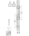
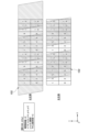
- Fig. 6 is an explanatory diagram for explaining how pixels on the display surface of the display 101 are seen by the observer P in Example 1-1.
- the pixels that can be seen by the right eye ER of the observer P due to the restriction by the parallax barrier as the optical element 102 are the 5th to 14th pixels (10 pixels).
- the pixels that can be seen by the left eye EL of the observer P due to the restriction by the parallax barrier as the optical element 102 are the 13th to 15th pixels and the 0th to 6th pixels (10 pixels).
- the 5th to 6th pixels and the 13th to 14th pixels are pixels that can be seen by both eyes of the observer P. For this reason, the 5th to 6th pixels and the 13th to 14th pixels are displayed in black.
- Example 7 is an explanatory diagram for explaining the operation of the display control unit 103 in Example 1-1.
- the display control unit 103 determines the evaluation overlap ranges "5th to 6th pixels” and "13th to 14th pixels” where the right eye evaluation pixel range “5th to 14th pixels” and the left eye evaluation pixel range "13th to 15th, 0th to 6th pixels” overlap. As a result, the display control unit 103 displays the evaluation overlap ranges "5th-6th pixels" and "13th-14th pixels” in black.
- FIG. 8 and 9 show an example in which the actual interocular distance E' of the observer P is shorter than the average interocular distance E of a person during the operation of the stereoscopic display device 100.
- the distance between the two central pixels on the right eye side and the two central pixels on the left eye side is shorter by one pixel than in the example 1-1 of FIG. 7 described above.
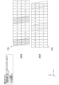
- FIG. 8 is an explanatory diagram for explaining how the pixels on the display surface of the display 101 are seen by the observer P in example 1-2.
- the pixels that can be viewed by the right eye ER of the observer P due to the restriction by the parallax barrier as the optical element 102 are the 4th to 13th pixels (10 pixels).
- the pixels that can be viewed by the left eye EL of the observer P due to the restriction by the parallax barrier as the optical element 102 are the 13th to 15th and 0th to 6th pixels (10 pixels).
- the fourth to sixth and thirteenth pixels are pixels that can be seen by both eyes of observer P. For this reason, the fourth to sixth and thirteenth pixels are displayed as black.
- the display control unit 103 determines the evaluation overlap range "4th to 6th, 13th pixels" where the right eye evaluation pixel range “4th to 13th pixels” and the left eye evaluation pixel range "13th to 15th, 0th to 6th pixels” overlap. As a result, the display control unit 103 displays the evaluation overlap range "4th to 6th, 13th pixels" in black.
- FIG. 10 and 11 show an example in which the actual interocular distance E' of the observer P is shorter than the average interocular distance E of a person during the operation of the stereoscopic display device 100.
- the distance between the two central pixels on the right eye side and the two central pixels on the left eye side is shorter by two pixels than in the example 1-1 of FIG. 7 described above.
- FIG. 10 is an explanatory diagram for explaining how pixels on the display surface of the display 101 are seen by the observer P in example 1-3.
- the pixels that can be viewed by the right eye ER of the observer P due to the restriction by the parallax barrier as the optical element 102 are the 4th to 13th pixels (10 pixels).
- the pixels that can be viewed by the left eye EL of the observer P due to the restriction by the parallax barrier as the optical element 102 are the 14th to 15th and 0th to 7th pixels (10 pixels).
- the fourth through seventh pixels are pixels that can be seen by both eyes of observer P. For this reason, the fourth through seventh pixels are displayed as black.
- the display control unit 103 determines the evaluation overlap range "4th to 7th pixels" where the right eye evaluation pixel range “4th to 13th pixels” and the left eye evaluation pixel range "14th to 15th, 0th to 7th pixels” overlap. As a result, the display control unit 103 displays the evaluation overlap range "4th to 7th pixels" in black.
- FIG. 12 and 13 show an example in which the actual interocular distance E' of the observer P is shorter than the average interocular distance E of a person during the operation of the stereoscopic display device 100.
- the distance between the two central pixels on the right eye side and the two central pixels on the left eye side is shorter by three pixels than in the example 1-1 of FIG. 7 described above.
- FIG. 12 is an explanatory diagram for explaining how the pixels on the display surface of the display 101 are seen by the observer P in example 1-4.
- the pixels that can be viewed by the right eye ER of the observer P due to the restriction by the parallax barrier as the optical element 102 are the 4th to 13th pixels (10 pixels).
- the pixels that can be viewed by the left eye EL of the observer P due to the restriction by the parallax barrier as the optical element 102 are the 15th and 0th to 8th pixels (10 pixels).
- the fourth through eighth pixels are visible to both eyes of observer P. For this reason, the fourth through eighth pixels are displayed as black.
- the display control unit 103 determines the evaluation overlap range "4th to 8th pixels" where the right eye evaluation pixel range “4th to 13th pixels” and the left eye evaluation pixel range "15th, 0th to 8th pixels” overlap. As a result, the display control unit 103 displays the evaluation overlap range "4th to 8th pixels” in black.
- [Aperture ratio: 25%] 14 to 19 are examples in which the designed aperture ratio of the parallax barrier serving as the optical element 102 is 25%.
- Example 2-1 in Figs. 14 and 15 is a case where the actual interocular distance E' of observer P is equal to the average interocular distance E of a person during the operation of the stereoscopic display device 100.
- Fig. 14 is an explanatory diagram for explaining how pixels on the display surface of the display 101 appear to observer P in Example 2-1.
- the pixels that can be viewed by observer P's right eye ER due to the restriction imposed by the parallax barrier as the optical element 102 are the 7th to 12th pixels (6 pixels).
- the pixels that can be viewed by observer P's left eye EL due to the restriction imposed by the parallax barrier as the optical element 102 are the 15th and 0th to 4th pixels (6 pixels).
- this Example 2-1 there are no pixels that can be viewed by observer P's both eyes. Therefore, there are no pixels that display black.
- FIG. 15 is an explanatory diagram for explaining the operation of the display control unit 103 in Example 2-1.
- the display control unit 103 determines that there is no evaluation overlap range, where the right eye evaluation pixel range "7th to 12th pixels" and the left eye evaluation pixel range "15th, 0th to 4th pixels" overlap. As a result, the display control unit 103 does not execute black display because there is no evaluation overlap range.
- FIG. 16 and 17 show an example in which the actual interocular distance E' of the observer P is shorter than the average interocular distance E of a person during the operation of the stereoscopic display device 100.
- the distance between the two central pixels on the right eye side and the two central pixels on the left eye side is shorter by three pixels than in the example 2-1 of FIG. 15 described above.
- FIG. 16 is an explanatory diagram for explaining how the pixels on the display surface of the display 101 are seen by the observer P in example 2-2.
- the pixels that can be viewed by the right eye ER of the observer P due to the restriction by the parallax barrier as the optical element 102 are the sixth to eleventh pixels (six pixels).
- the pixels that can be viewed by the left eye EL of the observer P due to the restriction by the parallax barrier as the optical element 102 are the first to sixth pixels (six pixels).
- the sixth pixel is a pixel that can be viewed by both eyes of the observer P. Therefore, the sixth pixel is displayed as black.
- the display control unit 103 determines the evaluation overlap range "6th pixel” where the right eye evaluation pixel range “6th to 11th pixels” and the left eye evaluation pixel range “1st to 6th pixels” overlap. As a result, the display control unit 103 displays the evaluation overlap range "sixth pixel" in black.
- FIG. 18 and 19 show an example in which the actual interocular distance E' of the observer P is shorter than the average interocular distance E of a person during the operation of the stereoscopic display device 100.
- the distance between the two central pixels on the right eye side and the two central pixels on the left eye side is shorter by four pixels than in the example 2-1 of FIG. 15 described above.
- FIG. 18 is an explanatory diagram for explaining how pixels on the display surface of the display 101 are seen by the observer P in example 2-3.
- the pixels that can be viewed by the right eye ER of the observer P due to the restriction by the parallax barrier as the optical element 102 are the 6th to 11th pixels (6 pixels).
- the pixels that can be viewed by the left eye EL of the observer P due to the restriction by the parallax barrier as the optical element 102 are the 2nd to 7th pixels (6 pixels).
- the 6th to 7th pixels are pixels that can be viewed by both eyes of the observer P. Therefore, the 6th and 7th pixels are displayed as black.
- the display control unit 103 determines the evaluation overlap range "6th to 7th pixels" where the right eye evaluation pixel range "6th to 11th pixels" and the left eye evaluation pixel range "2nd to 7th pixels” overlap. As a result, the display control unit 103 displays the evaluation overlap range "6th to 7th pixels" in black.
- the position of the right eye of the observer and the position of the left eye of the observer are acquired, the right eye image display pixel range of the right eye image to be assigned to the right eye position and the left eye image display pixel range of the left eye image to be assigned to the left eye position are determined, and the display is controlled to display the right eye image in the right eye image display pixel range and the left eye image in the left eye image display pixel range.
- This allows the right eye image and the left eye image to be assigned to appropriate pixels even if the observer moves arbitrarily, so that appropriate stereoscopic vision can be provided to the observer.
- the right eye image display pixel range and the left eye image display pixel range are determined to have a left-right overlap range that can be viewed by both the right eye and the left eye of the observer, and if a left-right overlap range is determined, the display is controlled to reduce the luminance of one or more pixels included in the left-right overlap range.
- the left-right overlap range changes depending on the observer's actual interocular distance and the observer's observation state (such as the posture of observer P, such as the tilt of the head or upper body), but according to this embodiment, by tracking the changes in the left-right overlap range, the effects of crosstalk due to the left-right overlap range can be reduced.
- this embodiment has the effect of improving stereoscopic vision for an observer who may be moving.
- a three-dimensional display device in a three-dimensional display device according to the prior art (see Patent Document 1), stereoscopic vision can be provided only under the condition that the interocular distance of the observer is equal to the average interocular distance of a person and both eyes of the observer are parallel to the display surface of the display.
- the interocular distance of the observer is assumed to the average interocular distance of a person, so when determining the range visible to the left eye and the range visible to the right eye on the display surface of the display, if the interocular distance is not equal to the average interocular distance, the range visible to the left eye and the range visible to the right eye cannot be correctly determined.
- the three-dimensional display device does not use the positions of the left eye and the right eye independently to determine the range visible to the left eye and the range visible to the right eye, so the range visible to the left eye and the range visible to the right eye cannot be correctly determined.
- the process of determining the visible range is performed on the assumption that the position of one eye is horizontally separated from the position of the other eye by a predetermined interocular distance.
- the process of determining that the position of the right eye is at a position moved horizontally from the position of the left eye by a predetermined interocular distance is permitted.
- the positions of the left eye and the right eye are not used independently to determine the range visible with the left eye and the range visible with the right eye.
- the right-eye evaluation pixel range and the left-eye evaluation pixel range are determined by independently using the three-dimensional coordinates of the position of the right eye ER and the three-dimensional coordinates of the position of the left eye EL of the observer P acquired by the position acquisition unit 105. Therefore, even if the interocular distance of the observer is not equal to the average interocular distance of a human, or even if both eyes of the observer are not parallel to the display surface of the display, the influence of crosstalk due to the left-right overlap range can be reduced by following the change in the left-right overlap range.
- the optical element 102 is a parallax barrier, but the present invention is not limited to this.
- the optical element 102 may be, for example, a lenticular lens.
- an example of the optical element 102 being a lenticular lens will be described.
- the stereoscopic display device according to this modification is referred to as a stereoscopic display device 100a. Note that the same components as those in the above-described embodiment are denoted by the same reference numerals, and descriptions of the same components and operations may be omitted.
- FIG. 22 is a diagram showing an example of a stereoscopic display device 100a according to this modified example.
- the stereoscopic display device 100a includes a display 101, a lenticular lens 91, a display control unit 103, a storage unit 104, and a position acquisition unit 105.
- the lenticular lens 91 is an example of an optical element.
- the lenticular lens 91 is composed of a plurality of cylindrical lenses 92.
- the lenticular lens 91 is configured by arranging a plurality of cylindrical lenses 92 extending in a second direction in a first direction.
- the lenticular lens 91 propagates a portion of the image light, which is light emitted from a subpixel to which a left-eye image ML is assigned, so that the light reaches the position of the left eye EL of the observer P.
- the lenticular lens 91 propagates a portion of the image light, which is light emitted from a subpixel to which a right-eye image MR is assigned, so that the light reaches the position of the right eye ER of the observer P.
- the lenticular lens 91 limits the left eye position, which is the position of the left eye EL at which the left-eye image ML can be viewed, and the right eye position, which is the position of the right eye ER at which the right-eye image MR can be viewed, by changing the direction in which light from the display surface of the display 101 propagates using the plurality of cylindrical lenses 92.
- Example 3-1 in FIG. 23 is an example of pixels viewed by the observer P due to the restriction of the lenticular lens 91. Since the lenticular lens has a light collecting effect, in many cases, only a part of the multiple pixels constituting the one-eye image (left-eye image ML or right-eye image MR) is observed.
- FIG. 23 shows a case where the state of the pixel observed through the lenticular lens is the same as the state of the pixel observed through a parallax barrier with an aperture ratio equivalent to 25%.
- These values may be determined at the time of designing the stereoscopic display device 100, or may be determined by evaluating the manufactured stereoscopic display device 100. When these values are determined by evaluating the manufactured stereoscopic display device 100, for example, the number of pixels per eye, q, is determined by illuminating each pixel of the observed display 101.
- FIG. 24 is an explanatory diagram for explaining the operation of the display control unit 103 in Example 3-1.
- the display control unit 103 determines that there is no evaluation overlap range, where the right eye evaluation pixel range "7th to 12th pixels" and the left eye evaluation pixel range "15th, 0th to 4th pixels" overlap. As a result, the display control unit 103 does not execute black display because there is no evaluation overlap range.
- FIG. 25 and 26 show an example in which the actual interocular distance E' of the observer P is shorter than the average interocular distance E of a person during the operation of the stereoscopic display device 100a.
- the distance between the two central pixels on the right eye side and the two central pixels on the left eye side is shorter by three pixels than in the example 3-1 of FIG. 24 described above.
- FIG. 25 is an explanatory diagram for explaining how the pixels on the display surface of the display 101 are seen by the observer P in example 3-2.
- the pixels that can be viewed by the right eye ER of the observer P due to the restriction imposed by the lenticular lens 91 as an optical element are the 6th to 11th pixels (6 pixels).
- the pixels that can be viewed by the left eye EL of the observer P due to the restriction imposed by the lenticular lens 91 as an optical element are the 1st to 6th pixels (6 pixels).
- the sixth pixel is a pixel that can be viewed by both eyes of the observer P. Therefore, the sixth pixel is displayed with reduced brightness (black).
- 26 is an explanatory diagram for explaining the operation of the display control unit 103 in Example 3-2.
- the display control unit 103 determines the evaluation overlap range "6th pixel” where the right eye evaluation pixel range “6th to 11th pixels” and the left eye evaluation pixel range "1st to 6th pixels” overlap. As a result, the display control unit 103 displays the evaluation overlap range "6th pixel” with reduced brightness (black display).
- the configuration of the display is not limited to the configuration shown in the above-mentioned embodiment and modified example.
- the pixels on the display surface of the display are composed of red subpixels, green subpixels, and blue subpixels, and the pixels are arranged in a lattice pattern in the first direction and the second direction
- the present invention is not limited to this.
- the pixels On the display surface, the pixels may be arranged based on a so-called delta arrangement in which the pixels are arranged with a half pitch shift for each row.
- the pixels may be arranged based on an arrangement called a honeycomb structure.
- the red subpixels, green subpixels, and blue subpixels may be arranged in stripes that are oblique to the second direction, rather than in stripes that are aligned along the second direction.
- the display may have square pixels arranged on the display surface, and display red sub-pixels, green sub-pixels, and blue sub-pixels in a time-division manner.
- a display such as an LED (light-emitting diode) display, one pixel may be configured by LED elements of three colors, RGB.
- the display is a self-luminous type
- a transmissive liquid crystal display and backlight may be used instead of the self-luminous display 101.
- the optical element may be disposed in front of the display surface of the liquid crystal display (i.e., on the viewer's side), as in the above-described embodiment and modified examples, or may be disposed between the liquid crystal display and the backlight.
- the first eye is the right eye ER of the observer P
- the second eye is the left eye EL of the observer P
- the first image is the right eye image MR
- the second image is the left eye image ML
- the right eye ER observes pixels assigned to the right eye image MR through the optical element 102
- the left eye EL observes pixels assigned to the left eye image ML through the optical element 102, thereby allowing the observer P to recognize a stereoscopic image.
- the image display device is a stereoscopic display device used for stereoscopic viewing, but the present invention is not limited to this.
- the configuration of the stereoscopic display device according to each embodiment may be used for purposes other than stereoscopic vision.
- the stereoscopic display device may be used to allow a plurality of observers to view different images when the observers view a display from different positions.
- the first eye is the eye of the first observer
- the second eye is the eye of a second observer located at a position different from the first observer
- the first image is a first observer image that is an image to be observed by the first observer
- the second image is a second observer image that is an image to be observed by the second observer
- the first eye of the first observer observes the pixels to which the first observer image is assigned through an optical element
- the second eye of the second observer observes the pixels to which the second observer image is assigned through an optical element
- the image display device (stereoscopic display device 100, 100a) according to this embodiment and the modified example includes a display 101, an optical element 102, a position acquisition unit 105, and a display control unit 103.
- the display 101 has a display surface including a plurality of pixels, and displays on the display surface a first image (in this embodiment, a right-eye image MR) to be viewed by the first eye (in this embodiment, the right eye ER) and a second image (in this embodiment, a left-eye image ML) to be viewed by the second eye (in this embodiment, the left eye EL).
- the optical element 102 limits a first eye position (in this embodiment, the position of the right eye ER), which is the position of the first eye (in this embodiment, the right eye ER) at which the first image (in this embodiment, the right eye image MR) can be viewed, and a second eye position (in this embodiment, the position of the left eye EL), which is the position of the second eye (in this embodiment, the left eye EL) at which the second image (in this embodiment, the left eye image ML) can be viewed.
- the position acquisition unit 105 acquires a first eye position (in this embodiment, the position of the right eye ER) and a second eye position (in this embodiment, the position of the left eye EL).
- the display control unit 103 uses the first eye position (in this embodiment, the position of the right eye ER) and the second eye position (in this embodiment, the position of the left eye EL) independently to determine a first image display pixel range (in this embodiment, the right eye image display pixel range) in which the first image (in this embodiment, the right eye image MR) is displayed based on the first eye position (in this embodiment, the position of the right eye ER), and determines a second image display pixel range (in this embodiment, the left eye image display pixel range) in which the second image (in this embodiment, the left eye image ML) is displayed based on the second eye position (in this embodiment, the position of the left eye EL), and controls the display 101 so that the first image (in this embodiment, the right eye image MR) is assigned to the pixels included in the first image display pixel range (in this embodiment, the right eye image display pixel range), and the second image (in this embodiment, the left eye image ML) is assigned to the pixels included in the second image display pixel range
- the display control unit 103 determines a both-eye overlap range (in this embodiment, a left-right overlap range) that can be seen by both the first eye (in this embodiment, the right eye ER) and the second eye (in this embodiment, the left eye EL) in the first image display pixel range (in this embodiment, the right eye image display pixel range) and the second image display pixel range (in this embodiment, the left eye image display pixel range), and when it determines that a both-eye overlap range (in this embodiment, a left-right overlap range) exists, controls the display 101 to reduce the brightness of one or more pixels included in the both-eye overlap range (in this embodiment, the left-right overlap range).
- a both-eye overlap range in this embodiment, a left-right overlap range
- the image display device (stereoscopic display device 100, 100a) according to this embodiment and modified example can acquire the position of the observer's eyes and assign the first image and the second image to appropriate pixels, thereby improving the visibility of the image even if the observer's eyes are not in a specified position.
- the observer's eyes are not in a specified position when, for example, the image display device is used for stereoscopic vision and the observer moves arbitrarily or the observer's interocular distance is not equal to the average human interocular distance.
- the observer's eyes are not in a specified position when, for example, the image display device is used as a multi-viewpoint display and multiple observers move arbitrarily.
- the stereoscopic display device is not limited to the above-described embodiment, and various modifications, substitutions, combinations, and/or design changes can be made without departing from the spirit of the present invention.
Landscapes
- Engineering & Computer Science (AREA)
- Multimedia (AREA)
- Signal Processing (AREA)
- Physics & Mathematics (AREA)
- Optics & Photonics (AREA)
- Testing, Inspecting, Measuring Of Stereoscopic Televisions And Televisions (AREA)
Priority Applications (1)
| Application Number | Priority Date | Filing Date | Title |
|---|---|---|---|
| JP2024564417A JPWO2024128264A1 (https=) | 2022-12-13 | 2023-12-13 |
Applications Claiming Priority (2)
| Application Number | Priority Date | Filing Date | Title |
|---|---|---|---|
| JP2022-198604 | 2022-12-13 | ||
| JP2022198604 | 2022-12-13 |
Publications (1)
| Publication Number | Publication Date |
|---|---|
| WO2024128264A1 true WO2024128264A1 (ja) | 2024-06-20 |
Family
ID=91485751
Family Applications (1)
| Application Number | Title | Priority Date | Filing Date |
|---|---|---|---|
| PCT/JP2023/044690 Ceased WO2024128264A1 (ja) | 2022-12-13 | 2023-12-13 | 映像表示装置 |
Country Status (2)
| Country | Link |
|---|---|
| JP (1) | JPWO2024128264A1 (https=) |
| WO (1) | WO2024128264A1 (https=) |
Cited By (2)
| Publication number | Priority date | Publication date | Assignee | Title |
|---|---|---|---|---|
| WO2025062810A1 (ja) * | 2023-09-22 | 2025-03-27 | 株式会社Jvcケンウッド | 画像表示装置、画像表示方法、及びプログラム |
| JP2026015125A (ja) * | 2024-07-18 | 2026-01-29 | 群創光電股▲ふん▼有限公司 | 3d表示装置および表示方法 |
Citations (4)
| Publication number | Priority date | Publication date | Assignee | Title |
|---|---|---|---|---|
| JP2014044396A (ja) * | 2012-07-31 | 2014-03-13 | Nlt Technologies Ltd | 立体画像表示装置、画像処理装置及び立体画像処理方法 |
| US20160173862A1 (en) * | 2014-12-10 | 2016-06-16 | Hisense Electric Co., Ltd. | Method and device for adjusting grayscale brightness and 3d display device |
| JP2022020434A (ja) * | 2020-07-20 | 2022-02-01 | 京セラ株式会社 | 3次元表示装置 |
| WO2022131137A1 (ja) * | 2020-12-14 | 2022-06-23 | 京セラ株式会社 | 3次元表示装置、画像表示システムおよび移動体 |
Family Cites Families (1)
| Publication number | Priority date | Publication date | Assignee | Title |
|---|---|---|---|---|
| JP7227116B2 (ja) * | 2019-10-01 | 2023-02-21 | 京セラ株式会社 | 3次元表示装置、コントローラ、3次元表示方法、3次元表示システム、及び、移動体 |
-
2023
- 2023-12-13 WO PCT/JP2023/044690 patent/WO2024128264A1/ja not_active Ceased
- 2023-12-13 JP JP2024564417A patent/JPWO2024128264A1/ja active Pending
Patent Citations (4)
| Publication number | Priority date | Publication date | Assignee | Title |
|---|---|---|---|---|
| JP2014044396A (ja) * | 2012-07-31 | 2014-03-13 | Nlt Technologies Ltd | 立体画像表示装置、画像処理装置及び立体画像処理方法 |
| US20160173862A1 (en) * | 2014-12-10 | 2016-06-16 | Hisense Electric Co., Ltd. | Method and device for adjusting grayscale brightness and 3d display device |
| JP2022020434A (ja) * | 2020-07-20 | 2022-02-01 | 京セラ株式会社 | 3次元表示装置 |
| WO2022131137A1 (ja) * | 2020-12-14 | 2022-06-23 | 京セラ株式会社 | 3次元表示装置、画像表示システムおよび移動体 |
Cited By (2)
| Publication number | Priority date | Publication date | Assignee | Title |
|---|---|---|---|---|
| WO2025062810A1 (ja) * | 2023-09-22 | 2025-03-27 | 株式会社Jvcケンウッド | 画像表示装置、画像表示方法、及びプログラム |
| JP2026015125A (ja) * | 2024-07-18 | 2026-01-29 | 群創光電股▲ふん▼有限公司 | 3d表示装置および表示方法 |
Also Published As
| Publication number | Publication date |
|---|---|
| JPWO2024128264A1 (https=) | 2024-06-20 |
Similar Documents
| Publication | Publication Date | Title |
|---|---|---|
| JP6443654B2 (ja) | 立体画像表示装置、端末装置、立体画像表示方法、及びそのプログラム | |
| JP5316909B2 (ja) | 立体画像表示装置、及び表示パネル | |
| TWI420152B (zh) | A Method of Multi - view Three - dimensional Image Display | |
| US8154799B2 (en) | 2D/3D switchable autostereoscopic display apparatus and method | |
| JP5809293B2 (ja) | 表示装置 | |
| JP5576762B2 (ja) | ディスプレイ制御装置 | |
| JP6154323B2 (ja) | 映像表示装置 | |
| TWI519129B (zh) | 顯示器與其控制方法 | |
| US20110242289A1 (en) | Display apparatus and stereoscopic image display method | |
| KR20150144439A (ko) | 입체 영상 표시 장치 | |
| JP5772688B2 (ja) | 裸眼立体ディスプレイ装置 | |
| CN102202223A (zh) | 多视图显示器 | |
| WO2024128264A1 (ja) | 映像表示装置 | |
| WO2017020473A1 (zh) | 三维显示装置及其显示方法 | |
| JP2016503512A (ja) | 自動立体表示装置及び画像を表示する方法 | |
| JP2012512435A (ja) | 空間的な表示のための方法と配置 | |
| TWI442094B (zh) | 使用基於次晶胞元素的視差屏障之立體顯示設備 | |
| CN102576155B (zh) | 视差屏障滤光器 | |
| CN108271013B (zh) | 显示装置及显示方法 | |
| TWI470274B (zh) | Three - dimensional image display device | |
| KR20140041102A (ko) | 표시 패널 및 이를 포함하는 표시 장치 | |
| JP2005157332A (ja) | 立体画像表示装置、携帯端末装置、表示パネル及びフライアイレンズ | |
| KR20040029755A (ko) | 입체 영상 디스플레이 장치 | |
| KR102153605B1 (ko) | 입체 영상 표시 장치 | |
| KR102904629B1 (ko) | 기울어진 픽셀 구조를 통해 크로스토크가 개선된 무안경 입체영상 표시장치 |
Legal Events
| Date | Code | Title | Description |
|---|---|---|---|
| 121 | Ep: the epo has been informed by wipo that ep was designated in this application |
Ref document number: 23903548 Country of ref document: EP Kind code of ref document: A1 |
|
| DPE1 | Request for preliminary examination filed after expiration of 19th month from priority date (pct application filed from 20040101) | ||
| WWE | Wipo information: entry into national phase |
Ref document number: 2024564417 Country of ref document: JP |
|
| NENP | Non-entry into the national phase |
Ref country code: DE |
|
| 122 | Ep: pct application non-entry in european phase |
Ref document number: 23903548 Country of ref document: EP Kind code of ref document: A1 |