WO2024128148A1 - 構造体製造装置および構造体製造方法 - Google Patents
構造体製造装置および構造体製造方法 Download PDFInfo
- Publication number
- WO2024128148A1 WO2024128148A1 PCT/JP2023/043961 JP2023043961W WO2024128148A1 WO 2024128148 A1 WO2024128148 A1 WO 2024128148A1 JP 2023043961 W JP2023043961 W JP 2023043961W WO 2024128148 A1 WO2024128148 A1 WO 2024128148A1
- Authority
- WO
- WIPO (PCT)
- Prior art keywords
- outer peripheral
- porous substrate
- peripheral side
- slurry
- sealing portion
- Prior art date
- Legal status (The legal status is an assumption and is not a legal conclusion. Google has not performed a legal analysis and makes no representation as to the accuracy of the status listed.)
- Ceased
Links
Images




Classifications
-
- B—PERFORMING OPERATIONS; TRANSPORTING
- B01—PHYSICAL OR CHEMICAL PROCESSES OR APPARATUS IN GENERAL
- B01J—CHEMICAL OR PHYSICAL PROCESSES, e.g. CATALYSIS OR COLLOID CHEMISTRY; THEIR RELEVANT APPARATUS
- B01J35/00—Catalysts, in general, characterised by their form or physical properties
- B01J35/50—Catalysts, in general, characterised by their form or physical properties characterised by their shape or configuration
- B01J35/56—Foraminous structures having flow-through passages or channels, e.g. grids or three-dimensional [3D] monoliths
- B01J35/57—Honeycombs
-
- B—PERFORMING OPERATIONS; TRANSPORTING
- B01—PHYSICAL OR CHEMICAL PROCESSES OR APPARATUS IN GENERAL
- B01J—CHEMICAL OR PHYSICAL PROCESSES, e.g. CATALYSIS OR COLLOID CHEMISTRY; THEIR RELEVANT APPARATUS
- B01J37/00—Processes, in general, for preparing catalysts; Processes, in general, for activation of catalysts
- B01J37/02—Impregnation, coating or precipitation
-
- C—CHEMISTRY; METALLURGY
- C04—CEMENTS; CONCRETE; ARTIFICIAL STONE; CERAMICS; REFRACTORIES
- C04B—LIME, MAGNESIA; SLAG; CEMENTS; COMPOSITIONS THEREOF, e.g. MORTARS, CONCRETE OR LIKE BUILDING MATERIALS; ARTIFICIAL STONE; CERAMICS; REFRACTORIES; TREATMENT OF NATURAL STONE
- C04B41/00—After-treatment of mortars, concrete, artificial stone or ceramics; Treatment of natural stone
- C04B41/80—After-treatment of mortars, concrete, artificial stone or ceramics; Treatment of natural stone of only ceramics
- C04B41/81—Coating or impregnation
- C04B41/85—Coating or impregnation with inorganic materials
Definitions
- This invention relates to a structure manufacturing apparatus and a structure manufacturing method, and in particular to a structure manufacturing apparatus and a structure manufacturing method that supply a slurry containing a functional material to a substrate.
- structure manufacturing apparatuses that supply a slurry containing a functional material to a substrate.
- a slurry containing a functional material for example, such an apparatus is disclosed in JP 2006-15205 A.
- JP 2006-15205 A describes a substrate coating device (structure manufacturing device). This substrate coating device coats a catalyst substrate of an exhaust gas purification catalyst with a catalyst slurry, which is a slurry containing a functional material that forms the catalyst. Specifically, the substrate coating device described in JP 2006-15205 A uses air pressure to make the catalyst slurry flow into multiple honeycomb channels formed in a columnar catalyst substrate. Multiple honeycomb channels are formed inside the columnar catalyst substrate, from the upper end surface of the catalyst substrate to the lower end surface. In the substrate coating device described in JP 2006-15205 A, the slurry is supplied so as to spread evenly over the upper end surface of the catalyst substrate, and is sucked in from the lower end side to flow into the honeycomb channels of the catalyst substrate.
- a porous substrate may be used as a catalyst substrate for forming a catalyst.
- the porous substrate is formed from a member having a porous structure, when a slurry layer is formed by filling the interior with slurry supplied to the upper end side by sucking air from the lower end side, air flows into the interior through the outer peripheral side surface other than the upper end surface. Due to this inflow of air from the outer peripheral side surface, it becomes difficult to form a slurry layer in the outer peripheral portion as viewed from the suction direction of the porous substrate.
- the length in the suction direction of the slurry layer formed in the outer peripheral portion of the porous substrate becomes smaller than the length in the suction direction of the slurry layer formed in the central portion. Therefore, when a slurry layer is formed inside the porous substrate, there is a problem in that the length of the slurry layer formed in the outer peripheral portion and the central portion differs.
- This invention was made to solve the above problems, and one objective of the invention is to provide a structure manufacturing apparatus and method that can reduce the difference in length of the slurry layer formed in the peripheral portion and the center portion when forming a slurry layer inside a porous substrate.
- the structure manufacturing apparatus includes a slurry supply unit that supplies a slurry containing a functional material that forms a functional layer to one end face of a porous substrate on which a functional layer is formed, a slurry suction unit that sucks the slurry supplied to the porous substrate by the slurry supply unit from the other end face of the porous substrate, and a shielding unit that covers the outer peripheral side face in a state spaced apart from the outer peripheral side face so as to block the inflow of air into the porous substrate from the outer peripheral side face along the direction in which the one end face and the other end face face each other.
- the structure manufacturing apparatus includes a shielding portion that covers the outer peripheral side surface while being spaced apart from the outer peripheral side surface so as to block the inflow of air from the outer peripheral side surface along the direction in which one end surface and the other end surface of the porous substrate face each other. This allows the shielding portion to block the inflow of air from the outer peripheral side surface of the porous substrate to the inside, thereby suppressing the difference in length of the slurry layer formed in the suction direction at the center portion and the outer peripheral portion as viewed from the suction direction of the porous substrate due to the inflow of air from the outer peripheral side surface.
- the shielding portion covers the outer peripheral side surface while being spaced apart from the outer peripheral side surface, it is possible to suppress the adhesion of the slurry seeping out from the outer peripheral side surface to the shielding portion. Therefore, it is possible to suppress the adhesion of the shielding portion to the porous substrate.
- one end of the shielding part is abutted against the outer peripheral side of the porous substrate to seal the outer peripheral side over the entire circumference
- the other end of the shielding part is abutted against the outer peripheral side of the porous substrate to seal the outer peripheral side over the entire circumference
- the shielding part covers the outer peripheral side from the one-side sealing part to the other-side sealing part.
- the shielding portion preferably shields a portion of the outer peripheral side surface that is larger than the total area of the abutting portions of the one-side sealing portion and the other-side sealing portion that abut against the outer peripheral side surface.
- slurry that seeps out from inside the porous substrate may adhere to the one-side sealing portion and the other-side sealing portion that abut against the outer peripheral side surface of the porous substrate.
- the one-side sealing portion and the other-side sealing portion are fixed to the outer peripheral side surface due to the attached slurry. This makes it necessary to peel off the one-side sealing portion and the other-side sealing portion, which increases the time required for the manufacturing operation.
- the portion of the outer peripheral side surface that is larger than the total area of the abutting portions is shielded by the shielding portion that is spaced apart from the outer peripheral side surface, so that the area of the shielded outer peripheral side surface can be increased while suppressing an increase in the area of the abutting portion. Therefore, the area of the shielded portion can be increased while suppressing an increase in the area of the abutting portion, which is the portion of the outer peripheral side surface that is fixed, so that the difference in the length of the slurry layer formed in the porous substrate can be further reduced while suppressing an increase in the time required for the manufacturing operation.
- the slurry supplying section supplies the slurry to one circular end face of the cylindrical porous substrate
- the shielding section has a cylindrical shape that conforms to the shape of the outer peripheral side face of the cylindrical porous substrate and has an inner diameter larger than the outer diameter of the outer peripheral side face of the porous substrate.
- the one-side sealing portion contacts the end of one side of the outer peripheral side surface of the porous substrate, thereby sealing the outer peripheral portion of the one end surface over the entire circumference.
- the one-side sealing portion seals the outer peripheral portion of the one end surface to which the slurry is supplied by the slurry supply portion over the entire circumference, and the one-side sealing portion, the other-side sealing portion, and the shielding portion can seal from the end of one side of the outer peripheral side surface to the position of the other-side sealing portion.
- the inflow of air from the outer peripheral side surface can be further suppressed, and the difference in length of the slurry layer formed in the porous substrate can be further reduced.
- the outer peripheral portion of the one end surface to which the slurry is supplied is sealed over the entire circumference, the supplied slurry can be suppressed from flowing out to the outer peripheral side surface.
- the porous substrate further includes a gripping portion that grips the outer peripheral side surface of the porous substrate from both sides, and the gripping portion grips the outer peripheral side surface on the other side of the other side sealing portion.
- the outer peripheral side surface on the other side of the other side sealing portion is gripped by the gripping portion, and the one-side sealing portion, the other-side sealing portion, and the shielding portion can be arranged so as to suppress the inflow of air from the outer peripheral side surface while the porous substrate is gripped by the gripping portion.
- an auxiliary sealing portion is provided separately from the other side sealing portion, which abuts against the other end of the outer peripheral side surface of the porous substrate to seal the entire outer peripheral portion of the other end surface, and the gripping portion grips the outer peripheral side surface between the other side sealing portion and the auxiliary sealing portion.
- the other-side sealing portion contacts the other end of the outer peripheral side surface of the porous substrate, thereby sealing the outer peripheral portion of the other end surface around the entire circumference.
- the other-side sealing portion seals the outer peripheral portion of the other end surface that is sucked in by the slurry suction portion around the entire circumference, and the one-side sealing portion, the other-side sealing portion, and the shielding portion can seal from the other end of the outer peripheral side surface to the position of the one-side sealing portion.
- the inflow of air from the outer peripheral side surface can be further suppressed, and the difference in length of the slurry layer formed in the porous substrate can be further reduced.
- the one-side sealing portion abuts against one end of the outer peripheral side surface of the porous substrate, thereby sealing the entire outer peripheral portion of one end surface, and the shielding portion covers the outer peripheral side surface from the one-side sealing portion that seals the outer peripheral portion of one end surface to the other-side sealing portion that seals the outer peripheral portion of the other end surface.
- the one-side sealing portion, the other-side sealing portion, and the shielding portion can seal the entire outer peripheral side surface from the end on one side to the end on the other side.
- the inflow of air from the outer peripheral side surface can be further suppressed, and the difference in length of the slurry layer formed in the porous substrate can be further reduced.
- the apparatus further includes a gripping part that grips the outer peripheral side surface of the porous substrate so as to sandwich the outer peripheral side surface from both sides
- the shielding part is formed integrally with the gripping part and includes a first shielding part and a second shielding part that cover the outer peripheral side surface so as to sandwich the outer peripheral side surface from both sides
- each of the first shielding part and the second shielding part is a plate-shaped member curved along the outer peripheral side surface of the porous substrate so that the gripping part covers the outer peripheral side surface by gripping the outer peripheral side surface.
- the first shielding part and the second shielding part formed integrally with the gripping part can shield the outer peripheral side surface by gripping the porous substrate with the gripping part. Therefore, compared to the case where the gripping part and the shielding part are provided separately, the porous substrate can be gripped and the outer peripheral side surface of the porous substrate can be shielded by one operation, and therefore an increase in manufacturing time can be suppressed when the difference in length of the slurry layer formed in the porous substrate is reduced.
- the slurry supply unit supplies a slurry containing a catalyst material, which is a functional material forming the catalyst layer, to one end face of the porous substrate on which a catalyst layer, which is a functional layer, is formed, and further includes a firing unit that performs a firing process on the porous substrate in a state in which the slurry containing the catalyst material is filled inside as a result of the slurry being supplied by the slurry supply unit and being sucked by the slurry suction unit.
- the method for manufacturing a structure according to a second aspect of the present invention includes the steps of: supplying a slurry containing a functional material forming a functional layer to one end face of a porous substrate in which a functional layer is formed; sucking the slurry supplied to the porous substrate from the other end face of the porous substrate; and, prior to the step of sucking the slurry, arranging a shielding portion that covers the outer peripheral side face in a state spaced apart from the outer peripheral side face so as to block air from entering the porous substrate from the outer peripheral side face along the direction in which the one end face and the other end face face each other.
- a shielding portion that covers the outer peripheral side is arranged in a state separated from the outer peripheral side so as to block the inflow of air from the outer peripheral side along the direction in which one end face and the other end face face each other.
- the shielding portion covers the outer peripheral side while being separated from the outer peripheral side, it is possible to suppress the adhesion of the slurry that seeps out from the outer peripheral side to the shielding portion. Therefore, it is possible to provide a structure manufacturing method that can suppress the adhesion of the shielding portion to the porous substrate.
- FIG. 1 is a block diagram showing an overall configuration of a structure manufacturing apparatus according to a first embodiment.
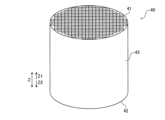
- FIG. 2 is a schematic diagram for explaining a porous substrate.
- FIG. 2 is a schematic diagram for explaining the internal structure of a porous substrate.
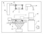
- FIG. 2 is a schematic diagram showing the configuration of a slurry application unit, illustrating a state in which a porous substrate is transported by a transport unit.
- FIG. 2 is a schematic diagram showing the configuration of a slurry application unit, in which a porous substrate is placed at a treatment position.
- 4 is a schematic diagram for explaining the configuration of an upper end sealing portion, a central sealing portion, a lower end sealing portion, and a shielding portion.
- FIG. FIG. 4 is a schematic diagram for explaining a baking section.
- FIG. 4 is a schematic diagram for explaining a baking section.
- FIG. 2 is a flowchart for explaining the structure manufacturing method according to the first embodiment.
- FIG. 2 is a diagram for explaining the arrangement of a porous substrate at a processing position.
- FIG. 13 is a diagram for explaining the arrangement of a shielding portion relative to a porous substrate.
- FIG. 11 is a block diagram showing the overall configuration of a structure manufacturing apparatus according to a second embodiment.
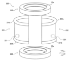
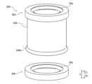
- 13 is a schematic diagram showing the configurations of an upper end sealing portion, a lower end sealing portion, and a shielding portion in a slurry application portion of a structure manufacturing apparatus according to a second embodiment.
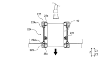
- FIG. 13 is a diagram showing schematic cross sections of an upper end sealing portion, a lower end sealing portion, and a shielding portion in a structure manufacturing apparatus according to a second embodiment.
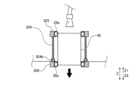
- FIG. 13 is a schematic diagram showing configurations of an upper end sealing portion, a lower end sealing portion, and a shielding portion in a slurry application unit of a structure manufacturing apparatus according to a modified example of the first embodiment.
- FIG. 15 is a schematic cross-sectional view of an upper end sealing portion, a lower end sealing portion, and a shielding portion in the structure manufacturing apparatus according to the modified example shown in FIG. 14 .
- the structure manufacturing apparatus 100 includes a substrate processing section 1 and a control section 2.
- the substrate processing section 1 includes a conveying section 10, a slurry application section 20, and a firing section 30.
- the structure manufacturing apparatus 100 is an apparatus in which the substrate processing section 1 applies a slurry containing a catalyst material, which is a functional material, to a porous substrate 40 (see Fig. 2) and performs a firing process on the porous substrate 40 to which the slurry has been applied, thereby forming a catalyst layer, which is a functional layer, inside the porous substrate 40.
- the control unit 2 controls each part of the structure manufacturing apparatus 100.
- the control unit 2 includes a calculation device such as a CPU (Central Processing Unit).
- the control unit 2 may also include a storage device such as a flash memory or a hard disk that stores programs or parameters executed by the calculation device.
- the operation of each part of the substrate processing unit 1 is controlled by the control process performed by the control unit 2.
- the porous substrate 40 is a honeycomb carrier having a cylindrical shape.
- the porous substrate 40 has an upper end surface 41, which is an end surface on the Z1 direction side (upper side), and a lower end surface 42, which is an end surface on the Z2 direction side (lower side), with the Z direction being the axial direction.
- the upper end surface 41 and the lower end surface 42 are circular and arranged to face each other along the Z direction.
- the porous substrate 40 has an outer peripheral side surface 43 along the Z direction. That is, the outer peripheral side surface 43 is a side surface of a cylinder.
- the porous substrate 40 has a porous structure through which air can pass.
- the porous substrate 40 is formed, for example, by sintering ceramic particles.
- the porous substrate 40 is used as a catalyst for purifying exhaust gas of a vehicle.
- the porous substrate 40 has an interior partitioned into a lattice shape along the Z direction.
- the Z1 direction side and the upper side are examples of "one side” in the claims.
- the Z2 direction side and the lower side are examples of "the other side” in the claims.
- the upper end surface 41 and the lower end surface 42 are examples of the "one end surface” and the “other end surface” in the claims, respectively.
- the porous substrate 40 has a plurality of partition walls 40a that divide the inside into a lattice shape along the Z direction.
- the porous substrate 40 has a plurality of cells, which are a plurality of regions divided by the plurality of partition walls 40a.
- Each of the plurality of cells is provided so as to extend from one end to the other end of the inside of the porous substrate 40 along the Z direction. That is, in the cylindrical porous substrate 40 extending along the Z direction, a plurality of cells having a rectangular cross section and extending along the Z direction are arranged in a lattice shape.
- the upper end surface 41 side (Z1 direction side) and the lower end surface 42 side (Z2 direction side) are alternately sealed. That is, the upper end surface 41 side and the lower end surface 42 side of adjacent cells are alternately sealed.
- the cross-sectional shape of the plurality of cells provided in the porous substrate 40 may be other shapes such as a triangle or a hexagon.
- a catalyst layer which is a functional layer, is formed inside the porous substrate 40.
- the structure manufacturing apparatus 100 supplies a slurry containing a catalyst material to the porous substrate 40, which is a honeycomb carrier, from the upper end surface 41 side on the Z1 direction side, and sucks in the slurry supplied from the lower end surface 42 side on the Z2 direction side, thereby filling the inside of the multiple cells with the catalyst material.
- the catalyst material is a functional material that forms a catalyst layer.
- a catalyst layer is formed on the partition wall 40a in each of the multiple cells.
- the catalyst layer formed on the porous substrate 40 purifies nitrogen compounds and the like contained in the exhaust gas.
- each of the multiple partition walls 40a included in the porous substrate 40 has a porous structure
- the exhaust gas flowing in from one side (for example, the Z1 direction side) of the porous substrate 40 passes through the partition wall 40a and then flows out from the other side (for example, the Z2 direction side).
- the exhaust gas is purified by passing through the catalyst layer formed on the partition wall 40a.
- the slurry contains precious metals such as platinum, palladium, and rhodium as catalyst materials.
- the slurry also contains water and organic solvents as dispersion media.
- the transport unit 10 transports the porous substrate 40 carried into the structure manufacturing apparatus 100.
- the transport unit 10 includes, for example, a belt conveyor.
- the transport unit 10 transports the porous substrate 40 to the slurry application unit 20, and transports the porous substrate 40 after the treatment by the slurry application unit 20.
- the transport unit 10 also transports the porous substrate 40 to the firing unit 30.
- the slurry application unit 20 applies slurry to the porous substrate 40 transported by the transport unit 10.
- the slurry application unit 20 has a gripping unit 21, a slurry supply unit 22, a slurry suction unit 23, a shielding unit 24, an upper end sealing unit 25, a lower end sealing unit 26, and a central sealing unit 27.
- Figures 4 and 5 show schematic cross sections of the slurry suction unit 23, the shielding unit 24, the upper end sealing unit 25, the lower end sealing unit 26, and the central sealing unit 27.
- the upper end sealing unit 25 is an example of a "one-side sealing unit” in the claims.
- the lower end sealing unit 26 is an example of an "auxiliary sealing unit” in the claims.
- the central sealing unit 27 is an example of an "other-side sealing unit” in the claims.
- the gripping unit 21 grips the outer peripheral side surface 43 of the porous substrate 40 so as to sandwich it from both sides.
- the gripping unit 21 includes a chuck mechanism such as a hand chuck.
- the gripping unit 21 grips the porous substrate 40 transported by the transport unit 10 and moves the porous substrate 40 to a processing position (see FIG. 5) where processing in which a slurry is supplied is performed.
- the gripping unit 21 is configured to be movable, for example, by a linear motion mechanism including a ball screw or the like, from a position where the porous substrate 40 is gripped by the transport unit 10 to a position where the porous substrate 40 is disposed at the processing position.
- the gripping unit 21 has a pair of contact portions that contact both sides of the outer peripheral side surface 43 of the porous substrate 40.
- the pair of contact portions are formed of an elastic member such as rubber.
- the slurry supply unit 22 supplies slurry to the upper end surface 41 of the porous substrate 40 placed at the processing position.
- the slurry supply unit 22 is configured to be movable. After the porous substrate 40 is placed at the processing position, the slurry supply unit 22 moves so that the slurry discharge port 22a is positioned above (on the Z1 direction side) the upper end surface 41, which is the end surface on the Z1 direction side of the porous substrate 40. The slurry supply unit 22 then discharges the slurry from the discharge port 22a to the upper end surface 41. At this time, the slurry supply unit 22 discharges the slurry while moving the discharge port 22a so as to spread the slurry evenly over the upper end surface 41.
- the slurry suction unit 23 sucks the slurry supplied to the porous substrate 40 by the slurry supply unit 22 from the lower end surface 42, which is the end surface on the Z2 direction side of the porous substrate 40.
- the slurry suction unit 23 includes a negative pressure generating means 23a such as a vacuum pump or an ejector.
- the slurry suction unit 23 fills the inside of the porous substrate 40 with the slurry supplied to the upper end surface 41 of the porous substrate 40 by sucking the air inside the porous substrate 40 downward (Z2 direction side) from the lower end surface 42 side.
- the shielding portion 24 covers the outer peripheral side surface 43 while being spaced apart from the outer peripheral side surface 43 so as to block the inflow of air from the outer peripheral side surface 43 into the porous substrate 40.
- the shielding portion 24 has a tubular shape.
- the shielding portion 24 has a cylindrical shape that conforms to the shape of the outer peripheral side surface 43 of the porous substrate 40, which has a cylindrical shape, and has an inner diameter larger than the outer diameter of the outer peripheral side surface 43 of the porous substrate 40.
- the shielding portion 24 is disposed so as to cover the entire circumference of the outer peripheral side surface 43 in the circumferential direction without abutting against the outer peripheral side surface 43.
- the shielding portion 24 is formed, for example, from metal or resin, and has a curved plate shape.
- the upper end sealing portion 25 contacts the Z1 direction end of the shielding portion 24 against the outer peripheral side surface 43 of the porous substrate 40, thereby sealing the entire outer peripheral side surface 43.
- the upper end sealing portion 25 contacts the Z1 direction end of the outer peripheral side surface 43 of the porous substrate 40, thereby sealing the entire outer peripheral portion of the upper end surface 41.
- the upper end sealing portion 25 seals the outer peripheral portion of the upper end surface 41 of the porous substrate 40, and the slurry supplying portion 22 supplies slurry to the upper end surface 41 with the outer peripheral portion sealed.
- the lower end sealing portion 26 abuts against the end of the outer peripheral side surface 43 of the porous substrate 40 on the Z2 direction side, thereby sealing the entire outer peripheral portion of the lower end surface 42.
- the lower end sealing portion 26 is provided at the suction port of the slurry suction portion 23. That is, the lower end sealing portion 26 seals the entire outer peripheral portion of the lower end surface 42 of the porous substrate 40, so that the slurry suction portion 23 sucks air from inside the porous substrate 40 through the lower end surface 42 in a state in which the outer peripheral portion is sealed.
- the end of the shielding portion 24 on the Z2 direction side is positioned at a position separated from the lower end sealing portion 26 when the slurry is supplied (see FIG. 5).
- the central sealing portion 27 contacts the outer peripheral side surface 43 of the porous substrate 40 at the end of the shielding portion 24 on the Z2 direction side, thereby sealing the outer peripheral side surface 43 over the entire circumference.
- the central sealing portion 27 contacts a portion of the outer peripheral side surface 43 that is lower (Z2 direction side) than the center position in the Z direction of the porous substrate 40.
- the gripping portion 21 grips a portion of the outer peripheral side surface 43 that is further lower (Z2 direction side) than the central sealing portion 27.
- the gripping portion 21 grips the outer peripheral side surface 43 between the central sealing portion 27 and the lower end sealing portion 26.
- the shielding portion 24 covers the outer peripheral side surface 43 from the upper end sealing portion 25 to the central sealing portion 27. In other words, the shielding portion 24 covers from the position of the upper end of the outer peripheral side surface 43 to the position sealed by the central sealing portion 27.
- the top sealing portion 25, the shielding portion 24, and the central sealing portion 27 are integrally configured.
- the top sealing portion 25, the shielding portion 24, and the central sealing portion 27 are integrally moved in the up-down direction (vertical direction: Z direction) by a linear motion mechanism 28 (see FIGS. 4 and 5).
- the linear motion mechanism 28 is disposed at the processing position, and moves the top sealing portion 25, the shielding portion 24, and the central sealing portion 27 so as to cover the porous substrate 40 from above while it is held by the holding portion 21.
- upper end sealing portion 25, lower end sealing portion 26, and central sealing portion 27 have support portion 25a, support portion 26a, and support portion 27a, respectively.
- Each of support portion 25a, support portion 26a, and support portion 27a is a balloon-type chuck having a circular ring shape.
- Each of support portion 25a, support portion 26a, and support portion 27a is hollow inside and formed from an elastic material such as rubber.
- Each of support portion 25a, support portion 26a, and support portion 27a expands toward the inside of the ring (toward the center of the Z axis) when air is sent inside.
- porous substrate 40 positioned inside the annular rings of the support parts 25a, 26a, and 27a, air is pumped into the insides of the support parts 25a, 26a, and 27a, and the porous substrate 40 is sealed around the entire outer peripheral side surface 43 in the circumferential direction.
- the shielding portion 24 shields a portion of the outer peripheral side surface 43 that is larger than the combined area of the contact portions of the upper end sealing portion 25 and the central sealing portion 27 that contact the outer peripheral side surface 43.
- the shielding portion 24 is provided to cover a portion of the outer peripheral side surface 43 that is larger than the area of the contact portions of the support portions 25a and 27a.
- the porous substrate 40 when the porous substrate 40 is held by the gripping section 21, three portions of the outer peripheral side surface 43 are sealed by the upper end sealing section 25, the lower end sealing section 26, and the central sealing section 27. Since the upper end sealing section 25 and the central sealing section 27 are integrally formed with the shielding section 24, the portion of the outer peripheral side surface 43 from the upper end sealing section 25 to the central sealing section 27 is covered by the shielding section 24, thereby suppressing the inflow of air into the inside. In other words, the outer peripheral side surface 43 above the position held by the gripping section 21 (Z1 direction side) is closed.
- the slurry is supplied from the slurry supply section 22 to the porous substrate 40 from the upper end surface 41 side, and the slurry supplied by the slurry suction section 23 is sucked from the lower end surface 42 side.
- the inside of the porous substrate 40 is filled with the slurry.
- the slurry does not need to fill the entire interior of the porous substrate 40 from the Z1 direction side to the Z2 direction side, but may fill only a portion of it.
- the calcination unit 30 performs a calcination process on the porous substrate 40, which is filled with slurry by the slurry supply unit 22 and the slurry suction unit 23.
- the transport unit 10 transports the porous substrate 40, which is filled with slurry, to the calcination unit 30.
- the calcination unit 30 heats the porous substrate 40 to perform a calcination process that forms a catalyst layer inside the porous substrate 40.
- the porous substrate 40 may be dried before the calcination process by the calcination unit 30.
- step S1 the porous substrate 40 is placed at a processing position where the slurry is supplied.
- the porous substrate 40 transported by the transport unit 10 is gripped by the gripping unit 21 and placed at the processing position.
- the porous substrate 40 placed at the processing position is held by the gripping portion 21, and the outer peripheral portion of the lower end surface 42 is sealed by the lower end sealing portion 26. That is, the gripping portion 21 places the porous substrate 40 at the processing position so that the lower end surface 42 is positioned to be sealed by the lower end sealing portion 26. Then, with the porous substrate 40 placed at the processing position, the lower end sealing portion 26 seals the entire outer peripheral portion of the lower end surface 42 by inflating the balloon-type chuck by sending air into the inside of the support portion 26a. At this point, the integrally formed upper end sealing portion 25, shielding portion 24, and center sealing portion 27 are waiting in a spaced-apart state above the porous substrate 40.
- the shielding portion 24 is positioned to cover the outer peripheral side surface 43 of the porous substrate 40 while being spaced apart from the outer peripheral side surface 43 so as to block the inflow of air from the outer peripheral side surface 43 into the inside of the porous substrate 40.
- the upper end sealing portion 25, the shielding portion 24, and the central sealing portion 27 are moved downward as a unit by the linear motion mechanism 28.
- the upper end sealing portion 25, the shielding portion 24, and the central sealing portion 27 are moved as a unit by the linear motion mechanism 28 so that the upper end surface 41 of the porous substrate 40 is positioned to be sealed by the upper end sealing portion 25.
- the support portion 25a of the upper end sealing portion 25 and the support portion 27a of the central sealing portion 27 are each in a state in which no air is being sent into the inside (a deflated state). Then, with the top end surface 41 positioned to be sealed by the top end sealing portion 25, air is pumped into the support portions 25a and 27a, causing the balloon-type zipper to inflate, sealing the outer periphery of the top end surface 41 and the position of the central sealing portion 27 on the outer periphery side surface 43 all around.
- step S3 the slurry is supplied to the upper end surface 41 of the porous substrate 40 by the slurry supply unit 22.
- step S4 the slurry supplied to the porous substrate 40 is sucked from the lower end surface 42 by the slurry suction unit 23.
- step S5 the porous substrate 40 with the slurry filled therein is subjected to a firing process by the firing unit 30.
- the structure manufacturing apparatus 100 of the first embodiment includes a shielding portion 24 that covers the outer peripheral side surface 43 in a state separated from the outer peripheral side surface 43 so as to block the inflow of air from the outer peripheral side surface 43 along the direction (Z direction) in which the upper end surface 41 (one end surface) and the lower end surface 42 (the other end surface) of the porous substrate 40 face each other.
- the difference in the length of the slurry layer formed in the outer peripheral part and the center part can be reduced.
- the shielding portion 24 covers the outer peripheral side surface 43 in a state separated from the outer peripheral side surface 43, it is possible to suppress the adhesion of the slurry that seeps out from the outer peripheral side surface 43 to the shielding portion 24. This prevents the shielding portion 24 from adhering to the porous substrate 40.
- the structure manufacturing apparatus 100 includes an upper end sealing portion 25 (one-side sealing portion) that seals the outer peripheral side surface 43 of the porous substrate 40 at an end portion on one side (Z1 direction side) of the shielding portion 24 by contacting the outer peripheral side surface 43 of the porous substrate 40, and a central sealing portion 27 (other-side sealing portion) that seals the outer peripheral side surface 43 of the porous substrate 40 at an end portion on the other side (Z2 direction side) of the shielding portion 24 by contacting the outer peripheral side surface 43 of the porous substrate 40.
- the shielding portion 24 covers the outer peripheral side surface 43 from the upper end sealing portion 25 to the central sealing portion 27.
- one side of the shielding portion 24 is sealed by the upper end sealing portion 25, and the other side of the shielding portion 24 is sealed by the central sealing portion 27, so that the outer peripheral side surface 43 surrounded by the upper end sealing portion 25, the central sealing portion 27, and the shielding portion 24 can be partitioned from the outside in a sealed state. Therefore, air can be prevented from flowing into the space surrounded by the upper end sealing portion 25, the central sealing portion 27, and the shielding portion 24, and differences in the length of the formed slurry layer can be prevented. As a result, when a slurry layer is formed inside the porous substrate 40, the difference in the length of the slurry layer formed in the outer periphery and the central portion can be reduced.
- the shielding portion 24 shields a portion of the outer peripheral side surface 43 that is larger than the total area of the abutting portions of the upper end sealing portion 25 (one side sealing portion) and the central sealing portion 27 (the other side sealing portion) that abut against the outer peripheral side surface 43.
- slurry that seeps out from inside the porous substrate 40 may adhere to the upper end sealing portion 25 and the central sealing portion 27 that abut against the outer peripheral side surface 43 of the porous substrate 40.
- the upper end sealing portion 25 and the central sealing portion 27 are fixed to the outer peripheral side surface 43 due to the adhered slurry. This makes it necessary to peel off the upper end sealing portion 25 and the central sealing portion 27, which increases the time required for the manufacturing operation.
- the shielding portion 24 that is spaced apart from the outer peripheral side surface 43 shields a portion of the outer peripheral side surface 43 that is larger than the total area of the abutting portions, so that the area of the outer peripheral side surface 43 that is shielded can be increased while suppressing an increase in the area of the abutting portions. Therefore, the area of the shielded portion can be increased while suppressing an increase in the area of the abutting portion, which is the portion of the outer peripheral side surface 43 that is fixed, and the difference in length of the slurry layer formed in the porous substrate 40 can be further reduced while suppressing an increase in the time required for manufacturing operations.
- the slurry supply unit 22 supplies the slurry to the circular upper end surface 41 (one end surface) of the porous substrate 40 having a cylindrical shape.
- the shielding unit 24 has a cylindrical shape that follows the shape of the outer peripheral side surface 43 of the porous substrate 40 having a cylindrical shape and has an inner diameter larger than the outer diameter of the outer peripheral side surface 43 of the porous substrate 40. This allows the shielding unit 24 to be arranged so as to follow the shape of the outer peripheral side surface 43 of the porous substrate 40, thereby preventing the volume of the space between the shielding unit 24 and the outer peripheral side surface 43 from increasing.
- the upper end sealing portion 25 (one side sealing portion) abuts against the end of one side (Z1 direction side) of the outer peripheral side surface 43 of the porous substrate 40, thereby sealing the outer peripheral portion of the upper end surface 41 (one end surface) over the entire circumference.
- the upper end sealing portion 25 seals the outer peripheral portion of the upper end surface 41 to which the slurry is supplied by the slurry supply portion 22 over the entire circumference, and the upper end sealing portion 25, the central sealing portion 27 (other side sealing portion), and the shielding portion 24 can seal from the end of one side of the outer peripheral side surface 43 to the position of the central sealing portion 27.
- the inflow of air from the outer peripheral side surface 43 can be further suppressed, and the difference in length of the slurry layer formed in the porous substrate 40 can be further reduced.
- the outer peripheral portion of the upper end surface 41 to which the slurry is supplied is sealed over the entire circumference, it is possible to suppress the supplied slurry from flowing out to the outer peripheral side surface 43 side.
- the structure manufacturing apparatus 100 is provided with a gripping portion 21 that grips the outer peripheral side surface 43 of the porous substrate 40 so as to sandwich it from both sides.
- the gripping portion 21 grips the outer peripheral side surface 43 on the other side of the central sealing portion 27 (other side sealing portion).
- the gripping portion 21 by gripping the outer peripheral side surface 43 on the other side (Z2 direction side) of the central sealing portion 27 with the gripping portion 21, it is possible to position the upper end sealing portion 25 (one side sealing portion), central sealing portion 27, and shielding portion 24 so as to suppress the inflow of air from the outer peripheral side surface 43 while the porous substrate 40 is gripped by the gripping portion 21.
- the difference in length of the slurry layer formed in the porous substrate 40 can be reduced without performing two extra operations: a retraction operation of retracting the gripping portion 21 from the porous substrate 40 before the slurry is suctioned, and a gripping operation of gripping the porous substrate 40 again by the gripping portion 21 after the slurry is suctioned.
- a retraction operation of retracting the gripping portion 21 from the porous substrate 40 before the slurry is suctioned a gripping operation of gripping the porous substrate 40 again by the gripping portion 21 after the slurry is suctioned.
- the structure manufacturing apparatus 100 includes a lower end sealing portion 26 (auxiliary sealing portion) that contacts the end of the other side (Z2 direction side) of the outer peripheral side surface 43 of the porous substrate 40 separately from the central sealing portion 27 (other side sealing portion) to seal the outer peripheral portion of the lower end surface 42 (other end surface) over the entire circumference.
- the gripping portion 21 grips the outer peripheral side surface 43 between the central sealing portion 27 and the lower end sealing portion 26.
- the lower end sealing portion 26 seals the outer peripheral portion of the lower end surface 42 sucked by the slurry suction portion 23, thereby preventing the slurry suction portion 23 from directly sucking in air outside the porous substrate 40.
- the slurry supply unit 22 supplies a slurry containing a catalyst material, which is a functional material for forming a catalyst layer, to the upper end surface 41 (one end surface) of the porous substrate 40 in which a catalyst layer, which is a functional layer, is formed.
- the structure manufacturing apparatus 100 includes a firing unit 30 that performs a firing process on the porous substrate 40 in which the slurry containing the catalyst material is supplied by the slurry supply unit 22 and the slurry is sucked by the slurry suction unit 23, and the slurry is filled inside.
- the difference in length of the slurry layer formed in the porous substrate 40 can be reduced by shielding the outer peripheral side surface 43 with the shielding unit 24. Therefore, the difference in length of the catalyst layer formed in the porous substrate 40 can be reduced.
- the structure manufacturing apparatus 200 includes a substrate processing section 201.
- the substrate processing section 201 also includes a slurry application section 220.
- the slurry application section 220 includes a gripping section 221, a shielding section 224, an upper end sealing section 225, and a lower end sealing section 226.
- the structure manufacturing apparatus 200 applies slurry to the porous substrate 40 in the slurry application section 220, similar to the structure manufacturing apparatus 100 according to the first embodiment.
- the shielding section 224 includes a first shielding section 251 and a second shielding section 252 that cover the outer peripheral side surface 43 so as to sandwich the outer peripheral side surface 43 from both sides.
- the upper end sealing section 225 and the lower end sealing section 226 are examples of the "one side sealing section" and the "other side sealing section” in the claims, respectively.
- each of the first shielding portion 251 and the second shielding portion 252 is formed integrally with the gripping portion 221.
- the gripping portion 22 like the gripping portion 21 of the first embodiment, grips the outer peripheral side surface 43 of the porous substrate 40 so as to sandwich it from both sides.
- the first shielding portion 251 and the second shielding portion 252 are arranged so as to correspond to each of a pair of abutment portions that abut against each of both sides of the outer peripheral side surface 43 of the porous substrate 40. That is, the first shielding portion 251 is formed integrally with one of the pair of abutment portions of the gripping portion 221, and the second shielding portion 252 is formed integrally with the other.
- each of the first shielding portion 251 and the second shielding portion 252 is a plate-shaped member curved to follow the outer peripheral side surface 43 of the porous substrate 40 so that the gripping portion 221 grips the outer peripheral side surface 43 to cover the outer peripheral side surface 43. That is, each of the first shielding portion 251 and the second shielding portion 252 has a shape obtained by dividing a cylindrical shape in half. The gripping portion 221 grips the outer peripheral side surface 43 of the porous substrate 40 so as to sandwich the outer peripheral side surface 43 from both sides, so that the first shielding portion 251 and the second shielding portion 252 are combined with each other.
- the first shielding portion 251 and the second shielding portion 252 are combined with each other so that the shielding portion 224 covers the entire circumference of the porous substrate 40. That is, each of the first shielding portion 251 and the second shielding portion 252 has a C-shape arranged to face each other when viewed from the Z1 direction side (upper side).
- the upper end sealing portion 225 contacts the outer peripheral side surface 43 of the porous substrate 40 at the end of the shielding portion 224 on the Z1 direction side, thereby sealing the outer peripheral side surface 43 over the entire circumference.
- the upper end sealing portion 225 also contacts the end of the outer peripheral side surface 43 of the porous substrate 40 on the Z1 direction side, thereby sealing the outer peripheral portion of the upper end surface 41 over the entire circumference.
- the upper end sealing portion 225 has a support portion 25a that is a balloon-type chuck having a circular ring shape, like the upper end sealing portion 25 of the first embodiment.
- the upper end sealing portion 225 is formed as a separate body from the shielding portion 224.
- the lower end sealing portion 226 seals the entire outer peripheral side surface 43 by abutting the Z2-direction end of the shielding portion 224 against the outer peripheral side surface 43 of the porous substrate 40.
- the lower end sealing portion 226 also seals the entire outer peripheral portion of the lower end surface 42 by abutting the Z2-direction end of the outer peripheral side surface 43 of the porous substrate 40.
- the lower end sealing portion 226 has a support portion 26a that is a balloon-type chuck having a circular ring shape, similar to the lower end sealing portion 26 of the first embodiment.
- the lower end sealing portion 226 is provided at the suction port of the slurry suction portion 23, similar to the lower end sealing portion 26 of the first embodiment, and is formed as a separate body from the shielding portion 224.
- the shielding portion 224 which is a combination of the first shielding portion 251 and the second shielding portion 252, covers the outer peripheral side surface 43 from the upper end sealing portion 225 that seals the outer peripheral portion of the upper end surface 41 to the lower end sealing portion 226 that seals the outer peripheral portion of the lower end surface 42.
- the shielding portion 224 is provided separately from the sealing portions (upper end sealing portion 225 and lower end sealing portion 226) that abut against the porous substrate 40, and is provided so as to cover the entire outer peripheral side surface 43 from the upper end surface 41 to the lower end surface 42 of the porous substrate 40.
- the shielding portion 224 also has a seal portion 224a and a seal portion 224b.
- Each of the seal portion 224a and the seal portion 224b is a tubular trim seal formed of an elastic member such as rubber.
- the seal portion 224a having a hollow cylindrical shape is arranged so as to follow the end face of the cylindrical shape at the end on the upper side (Z1 direction side).
- the seal portion 224b having a hollow cylindrical shape is arranged so as to follow the end face of the cylindrical shape at the end on the lower side (Z2 direction side).
- the porous substrate 40 transported by the transport unit 10 is held by the gripping portion 221 which is integrally formed with the shielding portion 224 (first shielding portion 251 and second shielding portion 252). That is, when the porous substrate 40 is held by the gripping portion 221, the outer peripheral side surface 43 is covered by the shielding portion 224 over the entire circumference.
- the porous substrate 40 held by the gripping portion 221 is then placed at the processing position (see FIG. 13) where the slurry is supplied.
- the sealing portion 224b on the lower side of the shielding portion 224 abuts against the lower end sealing portion 226. Specifically, the sealing portion 224b abuts against the portion of the lower end sealing portion 226 that is outer than the support portion 26a.
- the seal portion 224b elastically deforms and comes into contact with the lower end sealing portion 226, sealing the gap between the seal portion 224b and the lower end sealing portion 226. In this state, air is sent into the inside of the support portion 26a of the lower end sealing portion 226, sealing the outer periphery of the lower end surface 42 of the porous substrate 40.
- the upper end sealing portion 225 is moved downward by the linear motion mechanism 28.
- the upper side sealing portion 224a abuts against the upper end sealing portion 225, similar to the lower side sealing portion 224b.
- the sealing portion 224a abuts against the portion outside the support portion 25a of the upper end sealing portion 225 by being pressed against it. Therefore, the sealing portion 224a also abuts against the upper end sealing portion 225 while elastically deforming, thereby sealing the gap between the sealing portion 224a and the upper end sealing portion 225.
- the upper end sealing portion 225, the lower end sealing portion 226, and the shielding portion 224 (the first shielding portion 251 and the second shielding portion 252) seal the entire outer peripheral side surface 43 from the outer peripheral portion of the upper end surface 41 to the outer peripheral portion of the lower end surface 42, and the slurry supplying portion 22 supplies slurry to the upper end surface 41, and the slurry suction portion 23 sucks the slurry from the lower end surface 42.
- the lower end sealing portion 226 (other side sealing portion) abuts against the end portion on the Z2 direction side (other side) of the outer peripheral side surface 43 of the porous substrate 40, thereby sealing the outer peripheral portion of the lower end surface 42 (other end surface) over the entire circumference.
- the lower end sealing portion 226 seals the outer peripheral portion of the lower end surface 42 sucked by the slurry suction portion 23 over the entire circumference
- the upper end sealing portion 225 one side sealing portion
- the lower end sealing portion 226, and the shielding portion 224 can seal from the end portion on the Z2 direction side (other side) of the outer peripheral side surface 43 to the position of the upper end sealing portion 225.
- the inflow of air from the outer peripheral side surface 43 can be further suppressed, and the difference in length of the slurry layer formed in the porous substrate 40 can be further reduced.
- the upper end sealing portion 225 (one side sealing portion) abuts against the end portion on the Z1 direction side (one side) of the outer peripheral side surface 43 of the porous substrate 40, thereby sealing the entire outer peripheral portion of the upper end surface 41 (one end surface).
- the shielding portion 224 covers the outer peripheral side surface 43 from the upper end sealing portion 225 that seals the outer peripheral portion of the upper end surface 41 to the lower end sealing portion 226 (other side sealing portion) that seals the outer peripheral portion of the lower end surface 42 (other end surface).
- the upper end sealing portion 225, the lower end sealing portion 226, and the shielding portion 224 can seal the entire outer peripheral side surface 43 from the end portion on the Z1 direction side to the end portion on the Z2 direction side.
- the inflow of air from the outer peripheral side surface 43 can be further suppressed, and the difference in length of the slurry layer formed in the porous substrate 40 can be further reduced.
- the structure manufacturing apparatus 200 includes a gripping portion 221 that grips the outer peripheral side surface 43 of the porous substrate 40 so as to sandwich the outer peripheral side surface 43 from both sides.
- the shielding portion 224 is formed integrally with the gripping portion 221 and includes a first shielding portion 251 and a second shielding portion 252 that cover the outer peripheral side surface 43 so as to sandwich the outer peripheral side surface 43 from both sides.
- Each of the first shielding portion 251 and the second shielding portion 252 is a plate-shaped member that is curved to follow the outer peripheral side surface 43 of the porous substrate 40 so that the gripping portion 221 covers the outer peripheral side surface 43 by gripping the outer peripheral side surface 43.
- the porous substrate 40 can be gripped and the outer peripheral side surface 43 of the porous substrate 40 can be shielded with a single operation, so that an increase in manufacturing time can be suppressed when reducing the difference in length of the slurry layer formed in the porous substrate 40.
- the shielding portion 24, the upper end sealing portion 25 (one side sealing portion), and the central sealing portion 27 (the other side sealing portion) are integrally formed
- the shielding portion 224, the upper end sealing portion 225 (one side sealing portion), and the lower end sealing portion 226 (the other side sealing portion) are each formed as separate bodies, but the present invention is not limited to this.
- either one of the one side sealing portion or the other side sealing portion may be integrally formed with the shielding portion, and the other may be formed as a separate body from the shielding portion.
- the porous substrate 40 is shielded by the shielding portion 24 (224) when held by the gripping portion 21 (221), but the present invention is not limited to this.
- the outer peripheral side of the porous substrate may be covered by the shielding portion when the gripping portion is retracted from the porous substrate.
- the shielding portion 24, the upper end sealing portion 25 (one side sealing portion), and the central sealing portion 27 (the other side sealing portion) are integrally formed as in the first embodiment, after the gripping portion is retracted, the integrally formed shielding portion, one side sealing portion, and the other side sealing portion may move to cover the porous substrate.
- the shielding portion may be enlarged so that the other end portion (central sealing portion 27 in the first embodiment) that seals the outer peripheral side surface at the other end portion of the shielding portion and the lower end sealing portion that seals the outer peripheral portion of the other end face of the porous substrate over the entire circumference are arranged to abut against each other in the vertical direction (direction from one side to the other side). That is, the one side sealing portion, the other side sealing portion, and the shielding portion that are integrally formed, and the lower end sealing portion (auxiliary sealing portion) that seals the other end portion of the outer peripheral side surface of the porous substrate may seal the entire outer peripheral side surface from one side to the other side.
- an upper end sealing section 325 (an example of a one-side sealing section) may be formed integrally with the shielding section 324, and a lower end sealing section 326 (an example of a other-side sealing section) may be formed separately from the shielding section 324.
- the upper end sealing section 325 may be abutted against an end section on one side (Z1 direction side) of the porous substrate 40 to seal the entire outer periphery of the upper end surface 41 (one end surface).
- the lower end sealing section 326 may be abutted against an end section on the other side (Z2 direction side) of the porous substrate 40 to seal the entire outer periphery of the lower end surface 42 (other end surface).
- a seal portion 324b that is a trim seal may be provided at the lower end (Z2 direction side) of the shielding portion 324, similar to the seal portion 224b of the shielding portion 224 in the second embodiment. This provides a seal between the lower end of the shielding portion 324 and the bottom end sealing portion 326.
- the porous substrate 40 is first moved to a processing position where the slurry is supplied by the gripping portion 21 similar to that of the first embodiment. Then, the porous substrate 40 arranged at the processing position is supported by the support portion 26a of the lower end sealing portion 326. After that, the gripping portion 21 is retracted, and the shielding portion 324 and the upper end sealing portion 325 are moved downward together, so that the lower sealing portion 324b of the shielding portion 324 abuts against the lower end sealing portion 326.
- the support portion 25a of the upper end sealing portion 325 is inflated to seal the upper end surface 41 with the upper end sealing portion 325, and the entire outer peripheral side surface 43 from the upper end surface 41 to the lower end surface 42 of the porous substrate 40 is sealed by the shielding portion 324, the upper end sealing portion 325, and the lower end sealing portion 326.
- the upper end sealing portion 25, 225 (one-side sealing portion) that seals the outer peripheral side surface 43 at the end on the upper side (one side) of the shielding portion 24 (224) is an example that seals the outer peripheral portion of the upper end surface 41 (one end surface) of the porous substrate 40 over the entire circumference, but the present invention is not limited to this.
- the one-side sealing portion that seals the outer peripheral side surface at the end on one side of the shielding portion may seal the outer peripheral side surface on the other side of the one end surface of the porous substrate. Also, at least one of the one-side sealing portion and the other-side sealing portion may not be provided.
- the upper end sealing portion and the shielding portion may be arranged to be spaced apart from each other.
- the lower end sealing portion and the shielding portion may be arranged to be spaced apart from each other. That is, the position of the sealing portion does not have to be at the end of one side or the other side of the shielding portion. Also, at least one of the upper end sealing portion and the lower end sealing portion may not be provided.
- the shielding portion 24 is configured to shield a portion having an area larger than the total area of the abutting portions of the upper end sealing portion 25 (one-side sealing portion) and the central sealing portion 27 (the other-side sealing portion), but the present invention is not limited to this.
- the shielding portion may be configured to shield an area smaller than the total area of the abutting portions where the one-side sealing portion and the other-side sealing portion abut, or may be configured to shield an area approximately equal to the total area of the abutting portions.
- the porous substrate 40 has a cylindrical shape
- the present invention is not limited to this.
- the porous substrate may have a cross-sectional shape of a rectangular column such as a square or hexagon, or may have a cross-sectional shape of an elliptical column, etc. In that case, the shielding portion does not need to be formed to follow the external shape of the porous substrate.
- a baking unit 30 is provided to perform a baking process on the porous substrate 40 filled with a slurry, but the present invention is not limited to this. In the present invention, a baking unit does not necessarily have to be provided.
- the shielding portion 24 has a cylindrical shape
- the present invention is not limited to this.
- the shielding portion may have a tubular shape other than a cylindrical shape.
- the cross section of the shielding portion may be not only circular, but also polygonal, such as a square or hexagon, or may be elliptical.
Landscapes
- Chemical & Material Sciences (AREA)
- Engineering & Computer Science (AREA)
- Materials Engineering (AREA)
- Organic Chemistry (AREA)
- Ceramic Engineering (AREA)
- Chemical Kinetics & Catalysis (AREA)
- Inorganic Chemistry (AREA)
- Structural Engineering (AREA)
- Catalysts (AREA)
Priority Applications (1)
| Application Number | Priority Date | Filing Date | Title |
|---|---|---|---|
| JP2024564345A JPWO2024128148A1 (https=) | 2022-12-12 | 2023-12-08 |
Applications Claiming Priority (2)
| Application Number | Priority Date | Filing Date | Title |
|---|---|---|---|
| JP2022197761 | 2022-12-12 | ||
| JP2022-197761 | 2022-12-12 |
Publications (1)
| Publication Number | Publication Date |
|---|---|
| WO2024128148A1 true WO2024128148A1 (ja) | 2024-06-20 |
Family
ID=91484911
Family Applications (1)
| Application Number | Title | Priority Date | Filing Date |
|---|---|---|---|
| PCT/JP2023/043961 Ceased WO2024128148A1 (ja) | 2022-12-12 | 2023-12-08 | 構造体製造装置および構造体製造方法 |
Country Status (2)
| Country | Link |
|---|---|
| JP (1) | JPWO2024128148A1 (https=) |
| WO (1) | WO2024128148A1 (https=) |
Citations (6)
| Publication number | Priority date | Publication date | Assignee | Title |
|---|---|---|---|---|
| JP2003506211A (ja) * | 1999-08-06 | 2003-02-18 | エンゲルハード・コーポレーシヨン | 基質を触媒で被覆するシステム |
| JP2010017666A (ja) * | 2008-07-11 | 2010-01-28 | Tokyo Roki Co Ltd | 排ガス浄化用触媒 |
| JP2013516307A (ja) * | 2010-01-04 | 2013-05-13 | ジョンソン、マッセイ、パブリック、リミテッド、カンパニー | モノリス基材を触媒成分でコーティングする方法 |
| WO2018020777A1 (ja) * | 2016-07-27 | 2018-02-01 | 株式会社キャタラー | 排ガス浄化用触媒の製造方法及び製造装置 |
| JP2018153722A (ja) * | 2017-03-15 | 2018-10-04 | エヌ・イーケムキャット株式会社 | 排気ガス浄化触媒の製造方法 |
| WO2021150830A1 (en) * | 2020-01-22 | 2021-07-29 | Basf Corporation | Devices and methods for radially-zoned catalyst coating |
-
2023
- 2023-12-08 WO PCT/JP2023/043961 patent/WO2024128148A1/ja not_active Ceased
- 2023-12-08 JP JP2024564345A patent/JPWO2024128148A1/ja active Pending
Patent Citations (6)
| Publication number | Priority date | Publication date | Assignee | Title |
|---|---|---|---|---|
| JP2003506211A (ja) * | 1999-08-06 | 2003-02-18 | エンゲルハード・コーポレーシヨン | 基質を触媒で被覆するシステム |
| JP2010017666A (ja) * | 2008-07-11 | 2010-01-28 | Tokyo Roki Co Ltd | 排ガス浄化用触媒 |
| JP2013516307A (ja) * | 2010-01-04 | 2013-05-13 | ジョンソン、マッセイ、パブリック、リミテッド、カンパニー | モノリス基材を触媒成分でコーティングする方法 |
| WO2018020777A1 (ja) * | 2016-07-27 | 2018-02-01 | 株式会社キャタラー | 排ガス浄化用触媒の製造方法及び製造装置 |
| JP2018153722A (ja) * | 2017-03-15 | 2018-10-04 | エヌ・イーケムキャット株式会社 | 排気ガス浄化触媒の製造方法 |
| WO2021150830A1 (en) * | 2020-01-22 | 2021-07-29 | Basf Corporation | Devices and methods for radially-zoned catalyst coating |
Also Published As
| Publication number | Publication date |
|---|---|
| JPWO2024128148A1 (https=) | 2024-06-20 |
Similar Documents
| Publication | Publication Date | Title |
|---|---|---|
| JP4272765B2 (ja) | モノリシック触媒担体中の流路を被覆分散液で被覆する方法 | |
| TWI607833B (zh) | Substrate holding device and polishing device | |
| EP2858104B1 (en) | Flow path member, and adsorption device and refrigeration device employing same | |
| US10607870B2 (en) | Substrate carrier for active/passive bonding and de-bonding of a substrate | |
| EP2390898A2 (en) | Plasma processing apparatus and processing gas supply structure thereof | |
| JP2020530943A (ja) | 静電基板支持体幾何形状の研磨 | |
| KR20220027005A (ko) | 기판처리장치 | |
| WO2024128148A1 (ja) | 構造体製造装置および構造体製造方法 | |
| JP5362285B2 (ja) | 吸着ロール | |
| WO2015146635A1 (ja) | 基板処理装置 | |
| KR100778917B1 (ko) | 웨이퍼로부터 지지링을 분리하기 위한 홈을 갖춘웨이퍼캐리어 | |
| JP5183169B2 (ja) | ウェーハ処理装置 | |
| JP5199012B2 (ja) | チャックロール | |
| KR20190112149A (ko) | 프로세싱 챔버들을 위한 가스 분배 장치 | |
| JP7455609B2 (ja) | 搬送装置 | |
| JP4471747B2 (ja) | 半導体装置の製造装置 | |
| WO2024224656A1 (ja) | 構造体製造装置及び構造体製造方法 | |
| US7018273B1 (en) | Platen with diaphragm and method for optimizing wafer polishing | |
| JP4210170B2 (ja) | 真空対応型静圧気体軸受 | |
| JP7624912B2 (ja) | 排ガス浄化触媒装置の製造方法 | |
| CN103237403A (zh) | 电晕放电模式的大气等离子体发生装置 | |
| JP6746104B2 (ja) | セル内塗布装置及びそれを用いた反応容器の製造方法 | |
| KR102954486B1 (ko) | 유지 장치 | |
| JP7455941B1 (ja) | 触媒塗工装置用の器具、及び、触媒塗工装置 | |
| JP7845934B2 (ja) | 洗浄装置 |
Legal Events
| Date | Code | Title | Description |
|---|---|---|---|
| 121 | Ep: the epo has been informed by wipo that ep was designated in this application |
Ref document number: 23903435 Country of ref document: EP Kind code of ref document: A1 |
|
| WWE | Wipo information: entry into national phase |
Ref document number: 2024564345 Country of ref document: JP |
|
| NENP | Non-entry into the national phase |
Ref country code: DE |
|
| 122 | Ep: pct application non-entry in european phase |
Ref document number: 23903435 Country of ref document: EP Kind code of ref document: A1 |