WO2024128033A1 - 配線モジュール - Google Patents
配線モジュール Download PDFInfo
- Publication number
- WO2024128033A1 WO2024128033A1 PCT/JP2023/043098 JP2023043098W WO2024128033A1 WO 2024128033 A1 WO2024128033 A1 WO 2024128033A1 JP 2023043098 W JP2023043098 W JP 2023043098W WO 2024128033 A1 WO2024128033 A1 WO 2024128033A1
- Authority
- WO
- WIPO (PCT)
- Prior art keywords
- electric wire
- protector
- contact portion
- mounting surface
- electric wires
- Prior art date
- Legal status (The legal status is an assumption and is not a legal conclusion. Google has not performed a legal analysis and makes no representation as to the accuracy of the status listed.)
- Ceased
Links
Images


Classifications
-
- H—ELECTRICITY
- H01—ELECTRIC ELEMENTS
- H01M—PROCESSES OR MEANS, e.g. BATTERIES, FOR THE DIRECT CONVERSION OF CHEMICAL ENERGY INTO ELECTRICAL ENERGY
- H01M50/00—Constructional details or processes of manufacture of the non-active parts of electrochemical cells other than fuel cells, e.g. hybrid cells
- H01M50/20—Mountings; Secondary casings or frames; Racks, modules or packs; Suspension devices; Shock absorbers; Transport or carrying devices; Holders
- H01M50/204—Racks, modules or packs for multiple batteries or multiple cells
-
- H—ELECTRICITY
- H01—ELECTRIC ELEMENTS
- H01M—PROCESSES OR MEANS, e.g. BATTERIES, FOR THE DIRECT CONVERSION OF CHEMICAL ENERGY INTO ELECTRICAL ENERGY
- H01M50/00—Constructional details or processes of manufacture of the non-active parts of electrochemical cells other than fuel cells, e.g. hybrid cells
- H01M50/20—Mountings; Secondary casings or frames; Racks, modules or packs; Suspension devices; Shock absorbers; Transport or carrying devices; Holders
- H01M50/233—Mountings; Secondary casings or frames; Racks, modules or packs; Suspension devices; Shock absorbers; Transport or carrying devices; Holders characterised by physical properties of casings or racks, e.g. dimensions
- H01M50/242—Mountings; Secondary casings or frames; Racks, modules or packs; Suspension devices; Shock absorbers; Transport or carrying devices; Holders characterised by physical properties of casings or racks, e.g. dimensions adapted for protecting batteries against vibrations, collision impact or swelling
-
- H—ELECTRICITY
- H01—ELECTRIC ELEMENTS
- H01M—PROCESSES OR MEANS, e.g. BATTERIES, FOR THE DIRECT CONVERSION OF CHEMICAL ENERGY INTO ELECTRICAL ENERGY
- H01M50/00—Constructional details or processes of manufacture of the non-active parts of electrochemical cells other than fuel cells, e.g. hybrid cells
- H01M50/20—Mountings; Secondary casings or frames; Racks, modules or packs; Suspension devices; Shock absorbers; Transport or carrying devices; Holders
- H01M50/284—Mountings; Secondary casings or frames; Racks, modules or packs; Suspension devices; Shock absorbers; Transport or carrying devices; Holders with incorporated circuit boards, e.g. printed circuit boards [PCB]
-
- H—ELECTRICITY
- H01—ELECTRIC ELEMENTS
- H01M—PROCESSES OR MEANS, e.g. BATTERIES, FOR THE DIRECT CONVERSION OF CHEMICAL ENERGY INTO ELECTRICAL ENERGY
- H01M50/00—Constructional details or processes of manufacture of the non-active parts of electrochemical cells other than fuel cells, e.g. hybrid cells
- H01M50/20—Mountings; Secondary casings or frames; Racks, modules or packs; Suspension devices; Shock absorbers; Transport or carrying devices; Holders
- H01M50/298—Mountings; Secondary casings or frames; Racks, modules or packs; Suspension devices; Shock absorbers; Transport or carrying devices; Holders characterised by the wiring of battery packs
-
- H—ELECTRICITY
- H01—ELECTRIC ELEMENTS
- H01M—PROCESSES OR MEANS, e.g. BATTERIES, FOR THE DIRECT CONVERSION OF CHEMICAL ENERGY INTO ELECTRICAL ENERGY
- H01M50/00—Constructional details or processes of manufacture of the non-active parts of electrochemical cells other than fuel cells, e.g. hybrid cells
- H01M50/50—Current conducting connections for cells or batteries
- H01M50/502—Interconnectors for connecting terminals of adjacent batteries; Interconnectors for connecting cells outside a battery casing
- H01M50/507—Interconnectors for connecting terminals of adjacent batteries; Interconnectors for connecting cells outside a battery casing comprising an arrangement of two or more busbars within a container structure, e.g. busbar modules
-
- H—ELECTRICITY
- H01—ELECTRIC ELEMENTS
- H01M—PROCESSES OR MEANS, e.g. BATTERIES, FOR THE DIRECT CONVERSION OF CHEMICAL ENERGY INTO ELECTRICAL ENERGY
- H01M50/00—Constructional details or processes of manufacture of the non-active parts of electrochemical cells other than fuel cells, e.g. hybrid cells
- H01M50/50—Current conducting connections for cells or batteries
- H01M50/502—Interconnectors for connecting terminals of adjacent batteries; Interconnectors for connecting cells outside a battery casing
- H01M50/519—Interconnectors for connecting terminals of adjacent batteries; Interconnectors for connecting cells outside a battery casing comprising printed circuit boards [PCB]
-
- H—ELECTRICITY
- H01—ELECTRIC ELEMENTS
- H01M—PROCESSES OR MEANS, e.g. BATTERIES, FOR THE DIRECT CONVERSION OF CHEMICAL ENERGY INTO ELECTRICAL ENERGY
- H01M50/00—Constructional details or processes of manufacture of the non-active parts of electrochemical cells other than fuel cells, e.g. hybrid cells
- H01M50/50—Current conducting connections for cells or batteries
- H01M50/543—Terminals
- H01M50/547—Terminals characterised by the disposition of the terminals on the cells
- H01M50/55—Terminals characterised by the disposition of the terminals on the cells on the same side of the cell
-
- H—ELECTRICITY
- H01—ELECTRIC ELEMENTS
- H01M—PROCESSES OR MEANS, e.g. BATTERIES, FOR THE DIRECT CONVERSION OF CHEMICAL ENERGY INTO ELECTRICAL ENERGY
- H01M50/00—Constructional details or processes of manufacture of the non-active parts of electrochemical cells other than fuel cells, e.g. hybrid cells
- H01M50/50—Current conducting connections for cells or batteries
- H01M50/569—Constructional details of current conducting connections for detecting conditions inside cells or batteries, e.g. details of voltage sensing terminals
-
- Y—GENERAL TAGGING OF NEW TECHNOLOGICAL DEVELOPMENTS; GENERAL TAGGING OF CROSS-SECTIONAL TECHNOLOGIES SPANNING OVER SEVERAL SECTIONS OF THE IPC; TECHNICAL SUBJECTS COVERED BY FORMER USPC CROSS-REFERENCE ART COLLECTIONS [XRACs] AND DIGESTS
- Y02—TECHNOLOGIES OR APPLICATIONS FOR MITIGATION OR ADAPTATION AGAINST CLIMATE CHANGE
- Y02E—REDUCTION OF GREENHOUSE GAS [GHG] EMISSIONS, RELATED TO ENERGY GENERATION, TRANSMISSION OR DISTRIBUTION
- Y02E60/00—Enabling technologies; Technologies with a potential or indirect contribution to GHG emissions mitigation
- Y02E60/10—Energy storage using batteries
Definitions
- This disclosure relates to a wiring module.
- High-voltage battery packs used in electric vehicles, hybrid vehicles, etc. usually consist of multiple stacked batteries that are electrically connected in series or parallel by a wiring module.
- a battery connection module described in JP 2019-23996 A (Patent Document 1 below) is known as such a wiring module.
- the battery connection module described in Patent Document 1 is configured with a bus bar and a flexible circuit board connected to the bus bar.
- the wiring module may include a bus bar, a circuit board connected to the bus bar, and electric wires connected to the circuit board.
- the connection between the circuit board and the electric wires may be performed, for example, by soldering.
- the connection between the circuit board and the electric wires may be damaged, for example, when vibration or stress is applied to the electric wires.
- the wiring module of the present disclosure is a wiring module that is attached to a plurality of energy storage elements having electrode terminals, and includes a plurality of bus bars, a plurality of circuit boards, a plurality of electric wires, and a protector that holds the plurality of bus bars, the plurality of circuit boards, and the plurality of electric wires, where each of the bus bars is connected to the electrode terminal, each of the circuit boards is electrically connected to each of the bus bars, and each of the electric wires is connected to each of the circuit boards, and the protector has a wire accommodating section that accommodates the plurality of electric wires, a mounting surface on which each of the circuit boards is mounted, and a contact portion that is capable of contacting each of the electric wires arranged outside the wire accommodating section from the side opposite the mounting surface in a first direction perpendicular to the mounting surface.
- This disclosure provides a wiring module that can reduce damage to the connection between the circuit board and the electric wire.
- FIG. 1 is a schematic diagram showing a vehicle equipped with a power storage module according to a first embodiment.
- FIG. 2 is a plan view of the wiring module and the energy storage element.
- FIG. 3 is a plan view of the wiring module and the energy storage element with the cover removed.
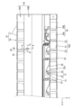
- FIG. 4 is a cross-sectional view taken along line AA of FIG.
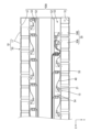
- FIG. 5 is a cross-sectional view taken along line BB of FIG.
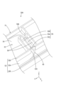
- FIG. 6 is an enlarged perspective view of the wiring module, illustrating the electric wires arranged outside the electric wire receiving portion and disposed within the recessed portion.
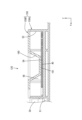
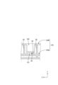
- FIG. 7 is a perspective view of the cover showing the contact portion.
- FIG. 8 is an enlarged plan view of the wiring module according to the second embodiment.
- FIG. 1 is a schematic diagram showing a vehicle equipped with a power storage module according to a first embodiment.
- FIG. 2 is a plan view of the wiring module and the energy storage element.
- FIG. 3 is a plan view of the wiring module and the
- FIG. 9 is a cross-sectional view taken along the line CC of FIG.
- FIG. 10 is a cross-sectional view taken along line DD of FIG.
- FIG. 11 is an enlarged perspective view of the wiring module showing the electric wires arranged outside the electric wire receiving portion.
- FIG. 12 is a perspective view of the cover showing the elastic piece.
- the wiring module of the present disclosure is a wiring module attached to a plurality of energy storage elements having electrode terminals, and includes a plurality of bus bars, a plurality of circuit boards, a plurality of electric wires, and a protector that holds the plurality of bus bars, the plurality of circuit boards, and the plurality of electric wires, where each of the bus bars is connected to the electrode terminal, each of the circuit boards is electrically connected to each of the bus bars, and each of the electric wires is connected to each of the circuit boards, and the protector has a wire housing portion in which the plurality of electric wires are housed, a mounting surface on which each of the circuit boards is mounted, and a contact portion that is capable of contacting each of the electric wires arranged outside the wire housing portion from the opposite side to the mounting surface in a first direction perpendicular to the mounting surface.
- orthogonal also includes an intersection that is recognized as being substantially orthogonal.
- each electric wire arranged outside the electric wire housing section comes into contact with the mounting surface and the contact section, and is subjected to friction from the mounting surface and the contact section. This makes it difficult for vibrations to be transmitted to the connections between each electric wire and each circuit board. Therefore, damage to the connections between each electric wire and each circuit board can be suppressed.
- the protector comprises a protector body and a cover that is overlapped with the protector body in the first direction, the protector body comprises the mounting surface described above, and the cover comprises the contact portion.
- This configuration allows the contact parts to be easily installed. It also makes it easier to route each electric wire to the protector.
- the protector has a recess recessed from the mounting surface, and the contact portion overlaps the recess when viewed from the first direction.
- each electric wire arranged outside the electric wire housing can be bent and placed inside the recess, and the contact portion can be pressed against each electric wire. This increases friction between the contact portion and each electric wire, further reducing damage to the connection portion between each electric wire and each circuit board.
- the distance in the first direction between the bottom surface of the recess and the contact portion is set to be larger than the diameter of each of the electric wires.
- the protector is elastically deformable in the first direction and has an elastic piece having the contact portion, and the elastic piece clamps each of the electric wires between the mounting surface.
- each electric wire arranged outside the electric wire housing is clamped between the elastic piece and the mounting surface, which increases the friction between each electric wire and the mounting surface and the contact portion. This further reduces damage to the connection between each electric wire and each circuit board.
- An electricity storage module 10 including a wiring module 20 of the present embodiment is applied to an electricity storage pack 2 mounted on a vehicle 1, for example, as shown in Fig. 1.
- the electricity storage pack 2 is mounted on a vehicle 1 such as an electric vehicle or a hybrid vehicle, and is used as a drive source for the vehicle 1.
- reference numerals may be assigned to only some of the members, and the reference numerals of the other members may be omitted.
- a power storage pack 2 is disposed near the center of a vehicle 1.
- a PCU 3 Power Control Unit
- the power storage pack 2 and the PCU 3 are connected by a wire harness 4.
- the power storage pack 2 and the wire harness 4 are connected by a connector (not shown).
- the power storage pack 2 has a power storage module 10 equipped with a plurality of power storage elements 11.
- the direction indicated by the arrow Z is the upward direction
- the direction indicated by the arrow X is the forward direction
- the direction indicated by the arrow Y is the leftward direction.
- the energy storage module 10 comprises a number of energy storage elements 11 arranged in a row, and a wiring module 20 attached to the upper surfaces of the multiple energy storage elements 11.
- the energy storage elements 11 are in the form of a flattened rectangular parallelepiped with energy storage elements housed inside.
- the energy storage elements 11 have a pair of electrode terminals located near the right end and the left end of the upper surface. One of the pair of electrode terminals is a positive electrode, and the other is a negative electrode.
- the wiring module 20 comprises a bus bar 30 connected to the electrode terminal of the storage element 11, a circuit board 21 connected to the bus bar 30, an electric wire 40 connected to the circuit board 21, and a protector 50 that holds the bus bar 30, the circuit board 21, and the electric wire 40.
- the busbar 30 is made of a metal plate material and has a rectangular shape in a plan view.
- the busbar 30 includes a connection busbar 30A that connects between adjacent electrode terminals in the stacking direction (front-rear direction) of the multiple energy storage elements 11, and an output busbar 30B that is connected to the electrode terminal of the energy storage element 11 arranged at the end in the stacking direction.
- the output busbar 30B connects the total positive electrode or total negative electrode of the multiple energy storage elements 11 to an external device.
- the busbar 30 is connected to the electrode terminal by welding or the like.
- the busbar 30 is accommodated in a busbar accommodating portion 51 of a protector 50 described later.
- the circuit board 21 is a flexible board, and is configured by forming a conductive path on the surface of a flexible insulating sheet by a printed wiring technology.
- the circuit board 21 includes a board body 22 and an extension portion 23 extending from the board body 22.
- the board body 22 has a substantially rectangular shape in a plan view.
- the board body 22 is fixed to a mounting surface 54 of a protector 50 described later.
- the board body 22 is provided with an insertion hole, and a protrusion protruding from the mounting surface 54 is inserted into the insertion hole.
- the board body 22 is provided with an electric wire land 22A arranged at one end of the conductive path.
- the electric wire land 22A is connected to the electric wire 40 by soldering or the like.
- the extension portion 23 is roughly U-shaped in a plan view and is configured to be expandable and contractible. The provision of the extension portion 23 allows the end portion (tip portion) of the extension portion 23 opposite the substrate body 22 to be displaced a predetermined dimension relative to the substrate body 22.
- the other end of the conductive path (not shown) is disposed at the tip portion of the extension portion 23. The other end of the conductive path is electrically connected to the bus bar 30 via the metal piece 15.
- circuit board 21 may have multiple conductive paths, and the conductive paths may include part of a thermistor circuit for measuring the temperature of the storage element 11.
- the electric wires 40 connected to the circuit board 21 are collectively accommodated in an electric wire housing portion 52 of the protector 50, which will be described later.
- the plurality of electric wires 40 are arranged to extend in the front-rear direction in the electric wire housing portion 52.
- the plurality of electric wires 40 may be integrated in the electric wire housing portion 52 by tape, a bundling member, or the like.
- the multiple electric wires 40 are connected to a connector (not shown) at the end opposite the circuit board 21.
- This connector is adapted to be connected to an external ECU (Electronic Control Unit) or the like.
- the ECU is equipped with a microcomputer, elements, etc., and is of a well-known configuration that has functions such as detecting the voltage, current, temperature, etc. of each storage element 11 and controlling the charging and discharging of each storage element 11.
- the protector 50 is made of insulating synthetic resin.
- the protector 50 includes a protector body 50A and a cover 50B that covers the protector body 50A from above.
- two covers 50B are provided for one protector body 50A.
- the protector body 50A is in the shape of a tray. As shown in Fig. 3, the protector body 50A includes a busbar accommodating portion 51 for accommodating the busbar 30, an electric wire accommodating portion 52 for accommodating the plurality of electric wires 40, and an intermediate wiring portion 53 arranged between the busbar accommodating portion 51 and the electric wire accommodating portion 52.
- the busbar accommodating portions 51 are provided at both ends in the left-right direction of the protector body 50A.
- the busbar accommodating portions 51 are frame-shaped and arranged side by side in the front-rear direction.
- the electric wire housing portions 52 are provided near the left-right center of the protector body 50A.
- the electric wire housing portions 52 are groove-shaped and extend in the front-rear direction.
- the electric wire housing portion 52 includes a bottom wall 52A and a pair of side walls 52B rising upward from both left and right end edges of the bottom wall 52A.
- a cutout portion 52C is formed in the side wall 52B on the intermediate wiring portion 53 side of the electric wire housing portion 52.
- the electric wire 40 is adapted to be received from the intermediate wiring portion 53 into the electric wire housing portion 52 through the cutout portion 52C.
- the intermediate wiring portion 53 has a circuit board 21 and an electric wire 40 connected to the circuit board 21.
- the intermediate wiring portion 53 has a mounting surface 54 on which the circuit board 21 is mounted, and a recess 55 recessed from the mounting surface 54 toward the energy storage element 11 (downward).
- the mounting surface 54 is a surface perpendicular to the up-down direction (an example of a first direction).
- the recess 55 has a rectangular shape that is long in the left-right direction in a plan view. As shown in FIG. 6, the recess 55 is disposed near the cutout portion 52C of the electric wire accommodating portion 52.
- the recess 55 has a bottom surface 55A that is approximately parallel to the mounting surface 54, and a first connection surface 55B and a second connection surface 55C that are connected to both left and right end edges of the bottom surface 55A.
- the first connection surface 55B and the second connection surface 55C connect the bottom surface 55A and the mounting surface 54.
- the second connection surface 55C is disposed closer to the wire accommodating portion 52 than the first connection surface 55B.
- the first connection surface 55B and the second connection surface 55C are inclined downward toward the bottom surface 55A.
- the intermediate wiring section 53 is disposed around the recess 55 and includes a partition wall 56 that rises upward from the mounting surface 54.
- the partition wall 56 is connected to the side wall 52B of the electric wire accommodating section 52.
- the partition wall 56 is provided with an opening 56A at a position opposite the cutout portion 52C in the left-right direction.
- the cover 50B is configured to be able to close the electric wire housing portion 52 and the intermediate wiring portion 53 of the protector body 50A from above.
- the cover 50B includes a top plate portion 57 and a contact portion 58 provided to protrude downward from the top plate portion 57.
- the contact portion 58 is, for example, block-shaped. The contact portion 58 is able to come into contact with the mounting surface 54 from the side opposite the mounting surface 54 in a first direction (vertical direction) perpendicular to the mounting surface 54.
- the contact portion 58 overlaps the recess 55 in a plan view, as shown by the dashed line in FIG. 2.
- the contact portion 58 is arranged inside the partition wall 56, and the electric wire 40 is arranged between the contact portion 58 and the bottom surface 55A of the recess 55. It is assumed that the electric wire 40 contacts the mounting surface 54 in the area between the connection portion with the circuit board 21 and the recess 55.
- the contact portion 58 is also arranged to press the electric wire 40 arranged on the recess 55 toward the bottom surface 55A of the recess 55.
- the lower end of the electric wire 40 is arranged below the mounting surface 54 in the recess 55, and the electric wire 40 is bent in the area from the outside to the inside of the recess 55.
- the lower end of the contact portion 58 is arranged at a position lower than the position of the upper end of the electric wire 40 placed on the mounting surface 54 in the vertical direction.
- the recess 55 has a first connection surface 55B and a second connection surface 55C at both ends of the bottom surface 55A in the extension direction (left-right direction) of the electric wire 40.
- the first connection surface 55B and the second connection surface 55C are provided with a downward inclination toward the bottom surface 55A. Therefore, when the electric wire 40 is pressed into the recess 55 by the contact portion 58, the electric wire 40 is easily bent, and the electric wire 40 is less likely to be damaged at both left and right ends of the recess 55.
- the distance D1 between the contact portion 58 and the bottom surface 55A of the recess 55 is larger than the diameter R1 of the electric wire 40. This makes it possible to prevent the electric wire 40 from being pinched between the contact portion 58 and the recess 55 and being damaged, even if the manufacturing tolerances of the contact portion 58 and the recess 55 are large.
- the wiring module 20 of the present embodiment Since the wiring module 20 of the present embodiment is used in the vehicle 1, it is considered that vibrations are applied to the electric wires 40.
- the vibrations applied to each electric wire 40 may become large.
- the electric wires 40 are connected to a connector, and it is considered that a tensile stress is applied to the electric wires 40 when the connector is connected to an external ECU or the like.
- the mounting surface 54 can contact the electric wires 40 from below, and the contact portion 58 can contact the electric wires 40 from above. Therefore, when vibration or tensile stress is applied to the electric wires 40, friction occurs between the electric wires 40 and the mounting surface 54 and the contact portion 58. This friction can prevent the vibration or tensile stress applied to the multiple electric wires 40 from being transmitted to the connection portion between the electric wires 40 and the circuit board 21 arranged outside the electric wire accommodating portion 52. Therefore, even when vibration or tensile stress is applied to the multiple electric wires 40, damage to the connection portion between the electric wires 40 and the circuit board 21 can be prevented.
- the wiring module 20 in the first embodiment is a wiring module 20 that is attached to a plurality of energy storage elements 11 having electrode terminals, and includes a plurality of bus bars 30, a plurality of circuit boards 21, a plurality of electric wires 40, and a protector 50 that holds the plurality of bus bars 30, the plurality of circuit boards 21, and the plurality of electric wires 40, wherein each bus bar 30 is connected to an electrode terminal, each circuit board 21 is electrically connected to each bus bar 30, and each electric wire 40 is connected to each circuit board 21, and the protector 50 has a wire accommodating section 52 in which the plurality of electric wires 40 are accommodated, a mounting surface 54 on which each circuit board 21 is placed and which is capable of contacting each electric wire 40 arranged outside the wire accommodating section 52, and a contact portion 58 which is capable of contacting each electric wire 40 arranged outside the wire accommodating section 52 from the side opposite to the mounting surface 54 in a first direction (up
- each electric wire 40 arranged outside the electric wire accommodating section 52 comes into contact with the mounting surface 54 and the contact portion 58, and is subjected to friction from the mounting surface 54 and the contact portion 58. This makes it difficult for vibrations to be transmitted to the connection portions between each electric wire 40 and each circuit board 21. Therefore, damage to the connection portions between each electric wire 40 and each circuit board 21 can be suppressed.
- the protector 50 includes a protector body 50A and a cover 50B that is overlapped with the protector body 50A in the first direction, the protector body 50A includes a mounting surface 54, and the cover 50B includes a contact portion 58.
- This configuration allows the contact portion 58 to be easily provided. It also makes it easier to route each electric wire 40 to the protector 50.
- the protector 50 has a recess 55 recessed from the mounting surface 54, and the contact portion 58 overlaps with the recess 55 when viewed from the first direction.
- each electric wire 40 arranged outside the electric wire housing portion 52 can be arranged in a bent state within the recess 55, and the contact portion 58 can be pressed against each electric wire 40. This increases friction between the contact portion 58 and each electric wire 40, and further suppresses damage to the connection portion between each electric wire 40 and each circuit board 21.
- the distance D1 in the first direction between the bottom surface 55A of the recess 55 and the contact portion 58 is set to be larger than the diameter R1 of each electric wire 40.
- FIG. 8 A second embodiment of the present disclosure will be described with reference to Fig. 8 to Fig. 12.
- the wiring module 120 according to the second embodiment is configured similarly to the first embodiment, except for the protector 150, and therefore descriptions of the same members and effects as those of the first embodiment will be omitted. Note that, for multiple identical members, only some of the members may be labeled with reference numerals, and the reference numerals of the other members may be omitted.
- the protector 150 of the wiring module 120 includes a protector body 150A and a cover 150B.
- the intermediate wiring section 153 of the protector body 150A has a mounting surface 54, but does not have the recess 55 of embodiment 1.
- the partition wall 56 is provided in the same position as in embodiment 1.
- the cover 150B has a top plate portion 57 and an elastic piece 160 extending from the top plate portion 57.
- the elastic piece 160 is elastically deformable in the up-down direction.
- the elastic piece 160 has a contact portion 161 in the center in the direction in which it extends (left-right direction).
- the contact portion 161 is in the shape of a plate extending horizontally.
- the contact portion 161 is provided on the elastic piece 160 that can elastically deform in the vertical direction, even if the electric wire 40 is clamped between the contact portion 161 and the mounting surface 54, the electric wire 40 is unlikely to be damaged.
- the protector 150 is elastically deformable in a first direction and includes an elastic piece 160 having a contact portion 161 , and the elastic piece 160 holds each electric wire 40 between itself and the mounting surface 54 .
- each electric wire 40 arranged outside the electric wire accommodating section 52 is clamped between the elastic piece 160 and the mounting surface 54, so that the friction between each electric wire 40 and the mounting surface 54 and the contact section 161 can be increased. Therefore, damage to the connection between each electric wire 40 and each circuit board 21 can be further suppressed.
- the protectors 50, 150 each include a protector body 50A, 150A and a cover 50B, 150B, respectively. However, this is not limited to this, and the protector may be configured from a single member.
- the circuit board 21 is a flexible board. However, this is not limited to this, and the circuit board may be a rigid board.
- the partition wall 56 is provided. However, the present invention is not limited to this, and the partition wall may be omitted.
- Wire harness 10 Energy storage module 11: Energy storage element 15: Small metal piece 20: Wiring module 21: Circuit board 22: Board body 22A: Wire land 23: Extension portion 30: Bus bar 30A: Connection bus bar 30B: Output bus bar 40: Electric wire 50, 150: Protector 50A, 150A: Protector body 50B, 150B: Cover 51: Bus bar accommodating portion 52: Electric wire accommodating portion 52A: Bottom wall 52B: Side wall 52C: Cutout portion 53, 153: Intermediate wiring portion 54: Placement surface 55: Recess 55A: Bottom surface 55B: First connection surface 55C: Second connection surface 56: Partition wall 56A: Opening 57: Top plate portion 58, 161: Contact portion 160: Elastic piece D1: Distance R1 between the bottom surface of the recess and the contact portion in the vertical direction: diameter of the electric wire
Landscapes
- Chemical & Material Sciences (AREA)
- Chemical Kinetics & Catalysis (AREA)
- Electrochemistry (AREA)
- General Chemical & Material Sciences (AREA)
- Battery Mounting, Suspending (AREA)
- Connection Of Batteries Or Terminals (AREA)
Priority Applications (1)
| Application Number | Priority Date | Filing Date | Title |
|---|---|---|---|
| CN202380084352.7A CN120322903A (zh) | 2022-12-16 | 2023-12-01 | 布线模块 |
Applications Claiming Priority (2)
| Application Number | Priority Date | Filing Date | Title |
|---|---|---|---|
| JP2022201118A JP7839470B2 (ja) | 2022-12-16 | 2022-12-16 | 配線モジュール |
| JP2022-201118 | 2022-12-16 |
Publications (1)
| Publication Number | Publication Date |
|---|---|
| WO2024128033A1 true WO2024128033A1 (ja) | 2024-06-20 |
Family
ID=91484869
Family Applications (1)
| Application Number | Title | Priority Date | Filing Date |
|---|---|---|---|
| PCT/JP2023/043098 Ceased WO2024128033A1 (ja) | 2022-12-16 | 2023-12-01 | 配線モジュール |
Country Status (3)
| Country | Link |
|---|---|
| JP (1) | JP7839470B2 (https=) |
| CN (1) | CN120322903A (https=) |
| WO (1) | WO2024128033A1 (https=) |
Citations (2)
| Publication number | Priority date | Publication date | Assignee | Title |
|---|---|---|---|---|
| JP2020035613A (ja) * | 2018-08-29 | 2020-03-05 | 住友電装株式会社 | 電池配線モジュール |
| JP2021136164A (ja) * | 2020-02-27 | 2021-09-13 | 矢崎総業株式会社 | バスバーモジュール |
Family Cites Families (1)
| Publication number | Priority date | Publication date | Assignee | Title |
|---|---|---|---|---|
| JP3881141B2 (ja) * | 1999-11-01 | 2007-02-14 | 株式会社リコー | 放送型情報システム、放送情報フィルタリング方法およびその方法をコンピュータに実行させるプログラムを記録したコンピュータ読み取り可能な記録媒体 |
-
2022
- 2022-12-16 JP JP2022201118A patent/JP7839470B2/ja active Active
-
2023
- 2023-12-01 WO PCT/JP2023/043098 patent/WO2024128033A1/ja not_active Ceased
- 2023-12-01 CN CN202380084352.7A patent/CN120322903A/zh active Pending
Patent Citations (2)
| Publication number | Priority date | Publication date | Assignee | Title |
|---|---|---|---|---|
| JP2020035613A (ja) * | 2018-08-29 | 2020-03-05 | 住友電装株式会社 | 電池配線モジュール |
| JP2021136164A (ja) * | 2020-02-27 | 2021-09-13 | 矢崎総業株式会社 | バスバーモジュール |
Also Published As
| Publication number | Publication date |
|---|---|
| JP2024086143A (ja) | 2024-06-27 |
| JP7839470B2 (ja) | 2026-04-02 |
| CN120322903A (zh) | 2025-07-15 |
Similar Documents
| Publication | Publication Date | Title |
|---|---|---|
| JP6940452B2 (ja) | 配線モジュール | |
| CN116457990B (zh) | 配线模块 | |
| JP2013080693A (ja) | 電池用配線モジュール | |
| WO2022009667A1 (ja) | 電池配線モジュール | |
| JP2017123280A (ja) | 電池モジュール | |
| JP7390324B2 (ja) | 配線モジュール | |
| CN116783769A (zh) | 外部连接汇流条及配线模块 | |
| WO2024128033A1 (ja) | 配線モジュール | |
| US12506227B2 (en) | Wiring module | |
| JP7159984B2 (ja) | 電池モジュール | |
| US20260096051A1 (en) | Electrical connection unit | |
| JP7769883B2 (ja) | 配線モジュール | |
| WO2024253060A1 (ja) | 配線モジュール | |
| JP7800412B2 (ja) | 配線モジュール | |
| US20250379376A1 (en) | Assembly | |
| US20250246762A1 (en) | Busbar module | |
| WO2024135548A1 (ja) | 配線モジュール | |
| JP2025183541A (ja) | 電気接続ユニット | |
| JP2025020733A (ja) | バスバー及び配線モジュール | |
| JP2024092370A (ja) | 電線と回路基板との接続構造、及び測温ユニット | |
| WO2025258470A1 (ja) | バスバー及び配線モジュール | |
| CN121753196A (zh) | 汇流条及布线模块 |
Legal Events
| Date | Code | Title | Description |
|---|---|---|---|
| 121 | Ep: the epo has been informed by wipo that ep was designated in this application |
Ref document number: 23903322 Country of ref document: EP Kind code of ref document: A1 |
|
| WWE | Wipo information: entry into national phase |
Ref document number: 202380084352.7 Country of ref document: CN |
|
| WWP | Wipo information: published in national office |
Ref document number: 202380084352.7 Country of ref document: CN |
|
| NENP | Non-entry into the national phase |
Ref country code: DE |
|
| 122 | Ep: pct application non-entry in european phase |
Ref document number: 23903322 Country of ref document: EP Kind code of ref document: A1 |