WO2024127618A1 - エアロゾル生成システム、及び情報処理方法 - Google Patents
エアロゾル生成システム、及び情報処理方法 Download PDFInfo
- Publication number
- WO2024127618A1 WO2024127618A1 PCT/JP2022/046321 JP2022046321W WO2024127618A1 WO 2024127618 A1 WO2024127618 A1 WO 2024127618A1 JP 2022046321 W JP2022046321 W JP 2022046321W WO 2024127618 A1 WO2024127618 A1 WO 2024127618A1
- Authority
- WO
- WIPO (PCT)
- Prior art keywords
- unit
- state detection
- heating
- mode
- detection unit
- Prior art date
- Legal status (The legal status is an assumption and is not a legal conclusion. Google has not performed a legal analysis and makes no representation as to the accuracy of the status listed.)
- Ceased
Links
Images







Classifications
-
- A—HUMAN NECESSITIES
- A24—TOBACCO; CIGARS; CIGARETTES; SIMULATED SMOKING DEVICES; SMOKERS' REQUISITES
- A24F—SMOKERS' REQUISITES; MATCH BOXES; SIMULATED SMOKING DEVICES
- A24F40/00—Electrically operated smoking devices; Component parts thereof; Manufacture thereof; Maintenance or testing thereof; Charging means specially adapted therefor
- A24F40/50—Control or monitoring
-
- A—HUMAN NECESSITIES
- A24—TOBACCO; CIGARS; CIGARETTES; SIMULATED SMOKING DEVICES; SMOKERS' REQUISITES
- A24F—SMOKERS' REQUISITES; MATCH BOXES; SIMULATED SMOKING DEVICES
- A24F40/00—Electrically operated smoking devices; Component parts thereof; Manufacture thereof; Maintenance or testing thereof; Charging means specially adapted therefor
- A24F40/10—Devices using liquid inhalable precursors
-
- A—HUMAN NECESSITIES
- A24—TOBACCO; CIGARS; CIGARETTES; SIMULATED SMOKING DEVICES; SMOKERS' REQUISITES
- A24F—SMOKERS' REQUISITES; MATCH BOXES; SIMULATED SMOKING DEVICES
- A24F40/00—Electrically operated smoking devices; Component parts thereof; Manufacture thereof; Maintenance or testing thereof; Charging means specially adapted therefor
- A24F40/20—Devices using solid inhalable precursors
-
- A—HUMAN NECESSITIES
- A24—TOBACCO; CIGARS; CIGARETTES; SIMULATED SMOKING DEVICES; SMOKERS' REQUISITES
- A24F—SMOKERS' REQUISITES; MATCH BOXES; SIMULATED SMOKING DEVICES
- A24F40/00—Electrically operated smoking devices; Component parts thereof; Manufacture thereof; Maintenance or testing thereof; Charging means specially adapted therefor
- A24F40/40—Constructional details, e.g. connection of cartridges and battery parts
- A24F40/46—Shape or structure of electric heating means
-
- A—HUMAN NECESSITIES
- A24—TOBACCO; CIGARS; CIGARETTES; SIMULATED SMOKING DEVICES; SMOKERS' REQUISITES
- A24F—SMOKERS' REQUISITES; MATCH BOXES; SIMULATED SMOKING DEVICES
- A24F40/00—Electrically operated smoking devices; Component parts thereof; Manufacture thereof; Maintenance or testing thereof; Charging means specially adapted therefor
- A24F40/50—Control or monitoring
- A24F40/51—Arrangement of sensors
-
- A—HUMAN NECESSITIES
- A24—TOBACCO; CIGARS; CIGARETTES; SIMULATED SMOKING DEVICES; SMOKERS' REQUISITES
- A24F—SMOKERS' REQUISITES; MATCH BOXES; SIMULATED SMOKING DEVICES
- A24F40/00—Electrically operated smoking devices; Component parts thereof; Manufacture thereof; Maintenance or testing thereof; Charging means specially adapted therefor
- A24F40/50—Control or monitoring
- A24F40/53—Monitoring, e.g. fault detection
-
- A—HUMAN NECESSITIES
- A24—TOBACCO; CIGARS; CIGARETTES; SIMULATED SMOKING DEVICES; SMOKERS' REQUISITES
- A24F—SMOKERS' REQUISITES; MATCH BOXES; SIMULATED SMOKING DEVICES
- A24F40/00—Electrically operated smoking devices; Component parts thereof; Manufacture thereof; Maintenance or testing thereof; Charging means specially adapted therefor
- A24F40/85—Maintenance, e.g. cleaning
Definitions
- This disclosure relates to an aerosol generation system and an information processing method.
- inhalation devices such as electronic cigarettes and nebulizers
- inhalation devices generate aerosol imparted with flavor components using a substrate that includes an aerosol source for generating aerosol and a flavor source for imparting flavor components to the generated aerosol.
- Users can taste the flavor by inhaling the aerosol imparted with flavor components generated by the inhalation device.
- the action of a user inhaling an aerosol is hereinafter also referred to as a puff or a puffing action.
- Patent Document 1 discloses a technology that emits light, detects the phosphorescent characteristics of the reflected light, and controls the operation of the suction device based on the detection results.
- the present disclosure has been made in light of the above problems, for example, and one of the aims of the present disclosure may be to provide a mechanism that can further improve the quality of the user experience.
- an aerosol generation system includes a storage unit having an internal space and an opening that connects the internal space to the outside, a first state detection unit and a second state detection unit that detect the state of the internal space, and a control unit that, when a detection value detected by the first state detection unit satisfies a first condition, switches the mode of the first state detection unit from an operation mode in which the state of the internal space is detected to a stop mode in which detection of the state of the internal space is stopped, and controls the mode of the second state detection unit to be switched from the stop mode to the operation mode.
- the aerosol generating system may further include a heating unit that heats the substrate contained in the container, and the control unit may control the heating by the heating unit based on the detection value obtained by the first state detection unit or the second state detection unit.
- the control unit may start heating by the heating unit when the detection value obtained by the second state detection unit satisfies the first condition.
- the control unit may control the second state detection unit to switch from the stop mode to the operation mode, and then, within a predetermined time, start heating by the heating unit if the detection value detected by the second state detection unit satisfies the first condition.
- the control unit may control one of the first state detection unit and the second state detection unit to the operation mode while the heating unit is heating, and control the other mode to the stop mode.
- the control unit may control the heating unit to stop heating when a detection value detected by the first state detection unit or the second state detection unit satisfies a second condition during heating by the heating unit.
- control unit may further switch the mode of the first state detection unit or the second state detection unit, which is the operation mode, to the stop mode, and may switch the mode of the first state detection unit or the second state detection unit, which is the stop mode, to the operation mode.
- the control unit may control the first state detection unit to switch the mode from the stop mode to the operation mode and the second state detection unit to switch the mode from the operation mode to the stop mode if the second state detection unit does not detect a detection value that satisfies the first condition within a predetermined time after switching the mode of the second state detection unit from the stop mode to the operation mode.
- the control unit may execute switching control for switching the modes of the first state detection unit and the second state detection unit multiple times so that the modes of the first state detection unit and the second state detection unit are switched, determine whether or not a first condition is satisfied each time switching control is executed, and control heating by the heating unit based on the multiple determination results.
- the control unit may execute the switching control when a detection value that satisfies the first condition is obtained by either the first state detection unit or the second state detection unit, or when a predetermined time has elapsed after controlling the second state detection unit to switch from the stop mode to the operation mode.
- the control unit may control the start of heating by the heating unit only when the first state detection unit and the second state detection unit have consecutively obtained detection values that satisfy the first condition a predetermined number of times.
- the control unit may prohibit heating by the heating unit if the first state detection unit and the second state detection unit do not obtain detection values that satisfy the first condition a predetermined number of times in succession.
- the first state detection unit and the second state detection unit may detect the state of the internal space by emitting light into the internal space and detecting the reflected light received.
- the aerosol generating system may further include a substrate contained in the container.
- an information processing method executed by a computer which includes controlling a first state detection unit that detects the state of an internal space of a storage unit having an internal space and an opening that connects the internal space to the outside, to switch the mode of the first state detection unit from an operation mode in which the state of the internal space is detected to a stop mode in which detection of the state of the internal space is stopped, and to switch the mode of a second state detection unit that detects the state of the internal space from the stop mode to the operation mode, when detection detected by the first state detection unit satisfies a first condition.
- this disclosure provides a mechanism that can further improve the quality of the user experience.
- FIG. 2 is a schematic diagram illustrating an example of the internal configuration of a suction device.
- 1 is an overall perspective view of a suction device 100 according to an embodiment of the present invention.
- FIG. 2 is an overall perspective view of the suction device 100 according to the present embodiment in a state in which a stick-shaped substrate 150 is held.
- 2 is a diagram showing a schematic configuration of a housing section 140 and its surroundings of the suction device 100 according to the present embodiment.
- FIG. FIG. 2 is a schematic diagram showing in detail the configuration in the vicinity of an optical sensor unit 170 of the suction device 100 according to the present embodiment.
- FIG. 2 is a schematic diagram of a housing section 140 of a suction device 100 according to the present embodiment, as viewed from an opening 142 side (i.e., from above).
- 2 is a block diagram showing a configuration of an optical sensor unit 170 in the suction device 100 according to the present embodiment.
- FIG. 4 is a diagram showing an example of the operation of the optical sensor unit 170 on the time axis.
- FIG. 11 is an explanatory diagram for explaining a specific example in which the detection control unit 179 transmits an interrupt notification.
- FIG. 1 is a diagram showing an example of the configuration of a cleaning item 190 according to the present embodiment.
- FIG. 1 is a diagram showing a schematic view of a housing section 140 with a stick-shaped substrate 150 inserted therein, as viewed from an opening 142 side (i.e., from above).
- FIG. 13 is a schematic diagram showing a state in which a storage section 140 with a cleaning item 190 inserted therein is viewed from the opening 142 side (i.e., from above).
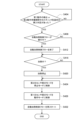
- 5 is a flowchart showing an example of the flow of a control process for automatic heating, which is executed by the suction device 100 according to the present embodiment.
- 11 is a flowchart showing an example of the flow of a process for determining an inserted item based on multiple replacement controls, which is executed by the suction device 100 according to this embodiment.
- 10 is a flowchart showing an example of the flow of a control process for automatic heating in response to a detection result of a sensor unit 112, which is executed by the suction device 100 according to the present embodiment.
- 10 is a flowchart showing an example of a flow of a control process for resetting an automatic heating control flow, which is executed by the suction device 100 according to the present embodiment.
- elements having substantially the same functional configuration may be distinguished by adding different letters after the same reference numeral.
- multiple elements having substantially the same functional configuration may be distinguished as optical sensor unit 170A and optical sensor unit 170B as necessary.
- only the same reference numeral may be used.
- optical sensor unit 170A and optical sensor unit 170B they will simply be referred to as optical sensor unit 170.
- FIG. 1 is a schematic diagram showing an example of the internal configuration of a suction device.
- a suction device 100 according to this example of configuration includes a power supply unit 111, a sensor unit 112, a notification unit 113, a storage unit 114, a communication unit 115, a control unit 116, a heating unit 121, a storage unit 140, and a heat insulating unit 144.
- the power supply unit 111 stores power.
- the power supply unit 111 supplies power to each component of the suction device 100 under the control of the control unit 116.
- the power supply unit 111 may be configured, for example, by a rechargeable battery such as a lithium ion secondary battery.
- the sensor unit 112 acquires various information related to the suction device 100.
- the sensor unit 112 is configured with a pressure sensor such as a condenser microphone, a flow sensor, or a temperature sensor, and acquires values associated with suction by the user.
- the sensor unit 112 is configured with an input device such as a button or switch that accepts information input from the user.
- the notification unit 113 notifies the user of information.
- the notification unit 113 is composed of, for example, a light-emitting device that emits light, a display device that displays an image, a sound output device that outputs sound, or a vibration device that vibrates.
- the storage unit 114 stores various information for the operation of the suction device 100.
- the storage unit 114 is configured, for example, from a non-volatile storage medium such as a flash memory.
- the communication unit 115 is a communication interface capable of performing communication conforming to any wired or wireless communication standard.
- Such communication standards may include, for example, standards using Wi-Fi (registered trademark), Bluetooth (registered trademark), BLE (Bluetooth Low Energy (registered trademark)), NFC (Near Field Communication), or LPWA (Low Power Wide Area).
- the control unit 116 functions as an arithmetic processing unit and a control unit, and controls the overall operation of the suction device 100 in accordance with various programs.
- the control unit 116 is realized by an electronic circuit such as a CPU (Central Processing Unit) or a microprocessor.
- the storage section 140 has an internal space 141 and holds the stick-shaped substrate 150 while storing a part of the stick-shaped substrate 150 in the internal space 141.
- the storage section 140 has an opening 142 that connects the internal space 141 to the outside, and stores the stick-shaped substrate 150 inserted into the internal space 141 through the opening 142.
- the storage section 140 is a cylindrical body with the opening 142 and the bottom 143 as the bottom surface, and defines a columnar internal space 141.
- An air flow path that supplies air to the internal space 141 is connected to the storage section 140.
- An air inlet hole which is an air inlet to the air flow path, is arranged, for example, on the side of the suction device 100.
- An air outlet hole which is an air outlet from the air flow path to the internal space 141, is arranged, for example, on the bottom 143.
- the stick-type substrate 150 includes a substrate portion 151 and a mouthpiece portion 152.
- the substrate portion 151 includes an aerosol source.
- the aerosol source includes a flavor component derived from tobacco or non-tobacco.
- the aerosol source may include a medicine.
- the aerosol source may be, for example, a liquid such as a polyhydric alcohol such as glycerin and propylene glycol, and water, which includes a flavor component derived from tobacco or non-tobacco, or may be a solid containing a flavor component derived from tobacco or non-tobacco.
- the stick-type substrate 150 When the stick-type substrate 150 is held in the storage portion 140, at least a part of the substrate portion 151 is stored in the internal space 141, and at least a part of the mouthpiece portion 152 protrudes from the opening 142.
- the heating unit 121 generates aerosol by heating the aerosol source and atomizing the aerosol source.
- the heating unit 121 is configured in a film shape and is arranged to cover the outer periphery of the storage unit 140.
- the heating unit 121 generates heat, the substrate unit 151 of the stick-shaped substrate 150 is heated from the outer periphery, and an aerosol is generated.
- the heating unit 121 generates heat when power is supplied from the power supply unit 111.
- power may be supplied when the sensor unit 112 detects that the user has started inhaling and/or that specific information has been input. Power supply may be stopped when the sensor unit 112 detects that the user has stopped inhaling and/or that specific information has been input.
- the insulating section 144 prevents heat transfer from the heating section 121 to other components.
- the insulating section 144 is made of a vacuum insulating material, an aerogel insulating material, or the like.
- the configuration of the suction device 100 is not limited to the above, and various configurations such as those exemplified below are possible.
- the heating unit 121 may be configured in a blade shape and disposed so as to protrude from the bottom 143 of the storage unit 140 into the internal space 141. In that case, the blade-shaped heating unit 121 is inserted into the substrate 151 of the stick-shaped substrate 150 and heats the substrate 151 of the stick-shaped substrate 150 from the inside. As another example, the heating unit 121 may be disposed so as to cover the bottom 143 of the storage unit 140. Furthermore, the heating unit 121 may be configured as a combination of two or more of a first heating unit that covers the outer periphery of the storage unit 140, a blade-shaped second heating unit, and a third heating unit that covers the bottom 143 of the storage unit 140.
- the storage unit 140 may include an opening/closing mechanism such as a hinge that opens and closes a portion of the outer shell that forms the internal space 141. The storage unit 140 may then open and close the outer shell to accommodate the stick-shaped substrate 150 inserted into the internal space 141 while clamping it.
- the heating unit 121 may be provided at the clamping location in the storage unit 140, and may heat the stick-shaped substrate 150 while pressing it.
- the means for atomizing the aerosol source is not limited to heating by the heating unit 121.
- the means for atomizing the aerosol source may be induction heating.
- the suction device 100 and the stick-shaped substrate 150 may be considered to cooperate with each other to generate an aerosol, constituting an aerosol generating system.
- the suction device 100 may be considered to include the stick-shaped substrate 150.
- FIG. 2 is an overall perspective view of the suction device 100 according to this embodiment.
- Fig. 3 is an overall perspective view of the suction device 100 according to this embodiment in a state in which a stick-type substrate 150 is held.
- the inhalation device 100 has a top housing 11A, a bottom housing 11B, a cover 12, a switch 13, a lid portion 14, an air vent 15, and a cap 16.
- the top housing 11A and the bottom housing 11B are connected to each other to form the outermost housing 11 of the inhalation device 100.
- the outer housing 11 is sized to fit in the user's hand. When the user uses the inhalation device 100, the user can hold the inhalation device 100 in their hand and inhale the flavor.
- the top housing 11A has an opening (not shown), and the cover 12 is coupled to the top housing 11A so as to close the opening.
- the cover 12 has an opening 142 into which the stick-shaped substrate 150 can be inserted.
- the lid portion 14 is configured to open and close the opening 142 of the cover 12.
- the switch 13 is used to switch the operation of the inhalation device 100 on and off.
- a user can insert the stick-shaped substrate 150 into the internal space 141 through the opening 142 and operate the switch 13 to supply power from the power supply unit 111 to the heating unit 121, thereby heating the stick-shaped substrate 150 without burning it.
- the stick-shaped substrate 150 is heated, an aerosol is generated from the aerosol source contained in the stick-shaped substrate 150, and the flavor of the flavor source is incorporated into the aerosol.
- the user can inhale the aerosol containing the flavor by inhaling the part of the stick-shaped substrate 150 protruding from the inhalation device 100 (the part shown in FIG. 3, i.e., the mouthpiece 152).
- the ventilation hole 15 is a ventilation hole for introducing air into the internal space 141.
- the air taken into the inside of the suction device 100 from the ventilation hole 15 is introduced into the internal space 141, for example, from the bottom 143 of the storage section 140.
- the cap 16 is configured to be detachable from the bottom housing 11B. When the cap 16 is attached to the bottom housing 11B, the ventilation hole 15 is formed between the bottom housing 11B and the cap 16.
- the cap 16 may have, for example, a through hole or a notch, not shown.
- Fig. 4 is a diagram showing a schematic configuration near the storage unit 140 of the suction device 100 according to this embodiment.
- Fig. 4 shows a schematic state in which the stick-shaped substrate 150 is stored in the storage unit 140.
- the suction device 100 includes a lid 14, a stick lower storage unit 140A, a guide unit 140B, an opening 142, a bottom 143, an optical sensor unit 170, and a circuit board 172.
- the direction in which the stick-shaped substrate 150 is inserted into or removed from the suction device 100 is also referred to as the up-down direction.
- the insertion direction of the stick-shaped substrate 150 is referred to as the down direction
- the removal direction of the stick-shaped substrate 150 is referred to as the up direction.
- the stick lower storage section 140A is a bottomed cylindrical body that constitutes part of the bottom 143 side of the storage section 140.
- the stick lower storage section 140A stores part of the bottom 143 side of the stick-shaped substrate 150 inserted into the internal space 141 from the opening 142.
- the guide portion 140B is a cylindrical body with openings on both ends that constitutes part of the storage portion 140 on the opening 142 side.
- the guide portion 140B accommodates the portion of the stick-shaped substrate 150 that is inserted into the internal space 141 from the opening 142 that is accommodated in the storage portion 140 and that is not accommodated in the lower stick storage portion 140A.
- the guide portion 140B functions as a guide to facilitate the insertion of the stick-shaped substrate 150 into the lower stick storage portion 140A.
- the guide portion 140B may be configured with a larger diameter than the lower stick storage portion 140A, or may be configured in a funnel shape with a gradually smaller diameter from top to bottom.
- the optical sensor unit 170 emits light into the internal space 141 and detects the reflected light it receives.
- the optical sensor unit 170 is an example of a detection unit in this embodiment, and is included in the sensor unit 112.
- the optical sensor unit 170 is, for example, an integrated circuit (IC) equipped with an infrared proximity sensor.
- the optical sensor unit 170 emits infrared light into the internal space 141 and detects the infrared light reflected by a detected object, such as an item contained in the internal space 141 or the inner wall of the storage unit 140.
- the optical sensor unit 170 is disposed in a location where it can emit light into the internal space 141.
- the optical sensor unit 170 is disposed in the guide unit 140B.
- the optical sensor unit 170 is embedded in the guide unit 140B.
- the optical sensor unit 170 detects light reflected by an object to be detected, such as an item contained in the internal space 141 or the inner wall of the guide unit 140B.
- the heating section 121 is arranged so as to cover the outer periphery of the lower stick storage section 140A.
- the heating section 121 is not arranged on the outer periphery of the guide section 140B.
- the guide section 140B may be made of a material with lower thermal conductivity than the material that makes up the lower stick storage section 140A. Therefore, the optical sensor section 170 is able to perform detection by light without being affected by the heating of the stick-shaped substrate 150.
- the inner wall of guide section 140B may be black. By making the inner wall of guide section 140B black, it is possible to suppress reflection of the light emitted by light sensor section 170.
- stick-shaped substrate 150 may be configured with a color that reflects light relatively easily, such as white, it is possible to make a large difference in the intensity of reflected light between when stick-shaped substrate 150 is inserted and when it is not.
- the circuit board 172 is a substrate on which the optical sensor unit 170 is mounted.
- the circuit board 172 is, for example, an FPC (Flexible Printed Circuits) circuit.
- the circuit board 172 is connected to the control unit 116 by, for example, a connector or solder.
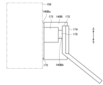
- FIG. 5 is a schematic diagram showing in detail the configuration of the optical sensor unit 170 and its surroundings of the suction device 100 according to this embodiment.
- the suction device 100 further includes a light-transmitting filter 173 and a reinforcing plate 174.
- the light-transmitting filter 173 is a filter that transmits the light emitted by the optical sensor unit 170.
- the light-transmitting filter 173 is an infrared-transmitting filter.
- the material of the light-transmitting filter 173 is not particularly limited, and may be resin or glass, or may be transparent resin with a light-transmitting coating.
- the light-transmitting filter 173 may be colored. By making the light-transmitting filter 173 colored, it is possible to hide the optical sensor unit 170 from the outside.
- a hole 140Bb is provided in the inner wall 140Ba of the guide unit 140B, and the optical sensor unit 170 is disposed so as to be embedded in the hole 140Bb.
- the light-transmitting filter 173 is disposed so as to block the hole 140Bb, and forms the inner wall 140Ba of the guide unit 140B. With this configuration, the inner wall 140Ba of the guide unit 140B can be made smooth. In addition, the light-transmitting filter 173 makes it possible to maintain an airtight seal so that sidestream smoke and other substances entering from outside the stick do not come into contact with the light sensor unit 170.
- Clearance 175 is a gap provided between the stick-shaped substrate 150 housed in the housing portion 140 and the inner wall 140Ba of the guide portion 140B. Clearance 175 may be provided so that the distance between the stick-shaped substrate 150 and the inner wall 140Ba of the guide portion 140B is 1 to 2 mm.
- the reinforcing plate 174 is a plate-like member having a certain rigidity.
- the reinforcing plate 174 is arranged to cover the back side of the circuit board 172 on which the optical sensor unit 170 is arranged on the front side, and reinforces the optical sensor unit 170 and the circuit board 172.
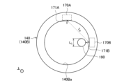
- FIG. 6 is a schematic diagram of the storage section 140 of the suction device 100 according to this embodiment, viewed from the opening 142 side (i.e., from above).
- the suction device 100 may have two optical sensor sections 170 (170A and 170B).
- the optical sensor section 170A and the optical sensor section 170B are examples of a first detection section, a first state detection section, and a second state detection section.
- the optical sensor section 170A and the optical sensor section 170B are disposed apart from each other, and the distance therebetween is L D.
- the direction 171A in which the optical sensor section 170A emits light (hereinafter also referred to as the radiation direction 171A) and the direction 171B in which the optical sensor section 170B emits light (hereinafter also referred to as the radiation direction 171B) form an angle ⁇ on a plane perpendicular to the up-down direction.
- the suction device 100 can more accurately determine the article inserted in the storage unit 140. The determination process using the optical sensor units 170 will be described in detail later.
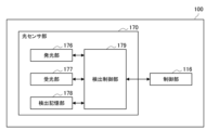
- Fig. 7 is a block diagram showing the configuration of optical sensor unit 170 in suction device 100 according to this embodiment.
- the optical sensor unit 170 includes a light emitting unit 176, a light receiving unit 177, a detection memory unit 178, and a detection control unit 179.
- the optical sensor unit 170 is connected to the control unit 116.
- the optical sensor unit 170 operates under the control of the control unit 116.
- the light-emitting unit 176 emits light into the internal space 141.
- the light-emitting unit 176 is composed of a light-emitting element such as an LD (Laser Diode) or an LED (Light Emitting Diode).
- the light-emitting unit 176 is an infrared LD and emits infrared light.
- the light-receiving unit 177 detects reflected light of the light emitted by the light-emitting unit 176.
- the infrared light emitted by the light-emitting unit 176 may be a VCSEL (Vertical Cavity Surface Emitting Laser). The operation of the light-emitting unit 176 will be described in detail with reference to Figure 8.
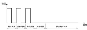
- FIG. 8 is a diagram showing an example of the operation of the optical sensor unit 170 on the time axis.
- the horizontal axis of FIG. 8 indicates time, with time flowing from left to right.
- the vertical axis of FIG. 8 indicates the intensity of light emitted by the light-emitting unit 176.
- the light-emitting unit 176 emits pulsed light at a predetermined cycle. This cycle is also called the operation cycle.
- the light-emitting unit 176 stops emitting light during the processing time and the intermittent operation time.
- the processing time is the time during which processing is performed based on the reflected light detected by the light-receiving unit 177.
- the intermittent operation time is the time until the next pulsed light emission is performed.
- the light-emitting unit 176 repeatedly executes a series of operations including the pulsed light emission and the stop of light emission, which have been described with reference to FIG. 8.
- the detection control unit 179 controls the operation of each component of the optical sensor unit 170. An example of the processing executed by the detection control unit 179 is described below. These processing are basically executed during the processing time described with reference to FIG. 8.
- the detection control unit 179 calculates a value indicating the intensity of the reflected light detected by the light receiving unit 177.
- the calculated value indicating the intensity of the reflected light is also referred to as the detection value below.
- the detection control unit 179 calculates a larger detection value as the intensity of the detected reflected light is stronger.
- the relationship between the intensity of the reflected light and the detection value may be linear.
- the detection control unit 179 may calculate the distance to the detected object that reflects the light emitted from the optical sensor unit 170, i.e., the distance between the detected object and the optical sensor unit 170, based on the detection value. In particular, the detection control unit 179 calculates a shorter distance as the detection value is larger, i.e., the intensity of the reflected light is stronger. On the other hand, the detection control unit 179 calculates a longer distance as the detection value is smaller, i.e., the intensity of the reflected light is weaker.
- the detection control unit 179 controls the operation of the light-emitting unit 176.
- the detection control unit 179 may control at least one of the number of pulse emissions, the operation cycle, and the intermittent operation time shown in FIG. 8.
- the detection control unit 179 may control the intensity of the infrared rays emitted by the light-emitting unit 176 by controlling the current value applied to the light-emitting unit 176 (hereinafter also referred to as the LD current value).
- the detection control unit 179 notifies the control unit 116 of information.
- the detection control unit 179 may store the calculated detection value in the detection storage unit 178. Then, when the detection value exceeds or falls below a predetermined threshold, the detection control unit 179 may notify the control unit 116 of that fact. Such a notification is also referred to as an interrupt notification below.
- the control unit 116 may read out the detection value stored in the detection storage unit 178, triggered by the reception of the interrupt notification.
- the detection control unit 179 may notify the control unit 116 of the calculated detection value by including it in the interrupt notification. Such processing regarding the detection value may also be performed regarding the distance to the detected object.
- the detection control unit 179 may notify the control unit 116 of the calculated distance.
- the detection control unit 179 may store the calculated distance in the detection storage unit 178, and when the calculated distance exceeds or falls below a predetermined threshold, notify the control unit 116 of that fact.
- the interrupt notification may be a notification indicating that an item has been inserted into or removed from the storage section 140.
- the control section 116 may execute a predetermined process in response to the reception of the interrupt notification.
- An example of the predetermined process may include determining whether or not a stick determination condition, which will be described later, has been satisfied, and controlling heating based on the determination result. With this configuration, the predetermined process is executed only when an interrupt notification has been received, which makes it possible to reduce the processing load on the control section 116.
- the detection control unit 179 may transmit an interrupt notification indicating that an item has been inserted into the storage unit 140 when the calculated detection value exceeds a predetermined threshold, the insertion threshold. Such an interrupt notification is also referred to below as a detection interrupt notification.
- the detection control unit 179 may also transmit an interrupt notification when the calculated detection value falls below a predetermined threshold, the removal threshold. Such an interrupt notification is also referred to below as a detection release interrupt notification.
- the detection interrupt notification may be sent when the detection control unit 179 calculates a detection value that is below the removal threshold for the first time after calculating a detection value that exceeds the insertion threshold.
- the detection release interrupt notification may be sent when the detection control unit 179 calculates a detection value that is below the removal threshold for the first time after calculating a detection value that exceeds the insertion threshold.
- the detection control unit 179 may update the insertion status managed (i.e., stored) in the detection memory unit 178 at the same time as sending the interrupt notification.
- the insertion status indicates whether or not an item is inserted in the storage unit 140.
- the detection control unit 179 may update the insertion status to "an item is inserted” at the same time as sending the detection interrupt notification.
- the detection control unit 179 may update the insertion status to "an item is not inserted” at the same time as sending the detection release interrupt notification.
- the detection control unit 179 may send the interrupt notification without distinguishing between a detection interrupt notification and a detection release interrupt notification.
- the control unit 116 may read out the insertion status stored in the detection memory unit 178, triggered by receiving the interrupt notification.
- FIG. 9 is an explanatory diagram for explaining a specific example of transmission of an interrupt notification by the detection control unit 179.
- the horizontal axis of FIG. 9 indicates time, with time flowing from left to right.
- the vertical axis of FIG. 9 indicates the detection value calculated by the detection control unit 179.
- FIG. 9 shows the change in detection value over time.
- the detection control unit 179 detects a detection value below the removal threshold at detection point P2. Therefore, the detection control unit 179 sends an interrupt notification at detection point P2 and updates the insertion status to no item inserted.
- the detection control unit 179 again detects a detection value above the insertion threshold at detection point P3. Therefore, the detection control unit 179 sends an interrupt notification at detection point P3 and updates the insertion status to an item inserted.
- the detection value may fluctuate up and down due to the influence of disturbances, noise in the power source supplied to the optical sensor unit 170, variations in the shape of the inserted item, variations in the distance between the inserted item and the light-emitting unit 176 and the light-receiving unit 177 due to contact between the user and the inserted item or the user holding the inserted item in his/her mouth, temperature drift of the detection value of the detection control unit 179 due to changes in the environmental temperature, or fluctuations in the roll diameter of the stick-shaped substrate 150 (insertion item) due to puffing during smoking.
- the insertion status can be prevented from changing unless a large vibration occurs that exceeds or falls below both the insertion threshold and the removal threshold. This makes it possible to prevent situations in which the insertion or non-insertion determination result changes frequently, and as a result, it becomes possible to accurately determine whether the inserted item is inserted or not.
- the detection control unit 179 may perform calibration. Specifically, the detection control unit 179 may adjust the relationship between the intensity of the reflected light detected by the light receiving unit 177 and the calculated detection value so as to calculate the same detection value under specified conditions. By performing calibration, it is possible to eliminate deviations in the detection value due to temperature or vibration, and to eliminate the effects of deterioration over time of the light emitting unit 176 or the light receiving unit 177.
- FIG. 8 shows an example in which the light-emitting unit 176 emits pulsed light three times
- the number of pulsed lights is not particularly limited.
- the detection control unit 179 may perform processing using the detection results from the multiple light-receiving unit 177, or may perform processing using some of the detection results from the multiple light-receiving unit 177.
- the detection memory unit 178 stores the programs executed by the detection control unit 179 and various data.
- the detection memory unit 178 is realized by, for example, a register.
- the detection memory unit 178 stores various setting values used during control by the detection control unit 179, such as the operation cycle of infrared pulse emission, intermittent operation time, insertion threshold, removal threshold, and LD current value.
- the control unit 116 and the detection control unit 179 communicate with each other.
- the control unit 116 and the detection control unit 179 communicate with each other via a serial communication interface such as I2C (Inter-Integrated Circuit) communication.
- the control unit 116 controls the operation of each component of the optical sensor unit 170 via the detection control unit 179.
- the control unit 116 controls the optical sensor unit 170 to switch between an operation mode in which reflected light is detected and a sleep mode in which reflected light detection is stopped. Specifically, in the sleep mode, the control unit 116 may control the light emitting unit 176 to stop emitting light, and may control the light receiving unit 177 to stop detecting reflected light. Also, in the operation mode, the control unit 116 controls the light emitting unit 176 to emit light and controls the light receiving unit 177 to detect reflected light. By controlling the switching of the mode of the optical sensor unit 170 by the control unit 116, it is possible to reduce power consumption compared to the case in which the optical sensor unit 170 constantly detects reflected light.
- the control unit 116 also stores various setting values used during control by the detection control unit 179 in the detection storage unit 178.
- the control unit 116 also receives various information such as interrupt notifications from the detection control unit 179, and reads out information stored in the detection storage unit 178.
- the detection memory unit 178 may be configured with a volatile storage medium or may be configured with a non-volatile storage medium. If the detection memory unit 178 is configured with a non-volatile storage medium, when power supply to the optical sensor unit 170 is interrupted and then is supplied again, the various setting values stored in the detection memory unit 178 are initialized. When the various setting values are initialized, the control unit 116 may store the various setting values before initialization again in the detection memory unit 178.
- the control unit 116 may control the optical sensor unit 170 to be in a power off mode in which power supply to the optical sensor unit 170 is stopped.
- the control unit 116 stores various setting values before initialization in the detection storage unit 178 again when switching the mode of the optical sensor unit 170 from the power off mode to the operation mode.
- the control unit 116 may control to maintain power supply to the detection storage unit 178 included in the optical sensor unit 170. This eliminates the need to store various setting values before initialization in the detection storage unit 178 again every time the sleep mode is switched to the operation mode when the detection storage unit 178 is configured with a volatile storage medium.
- control unit 116 may control to maintain power supply only to a part of the memory of the detection storage unit 178 included in the optical sensor unit 170.
- the sleep mode and the power off mode may be referred to as a stop mode as a general term for modes in which detection is stopped.
- the condition for transmitting the interrupt notification may be provided with an exception when the optical sensor unit 170 returns to the operating mode from the sleep mode.
- the detection interrupt notification is transmitted when the detection control unit 179 detects a detection value below the removal threshold and then detects a detection value exceeding the insertion threshold for the first time.
- the detection interrupt notification may be transmitted when the detection value exceeding the insertion threshold is detected even if the detection value below the removal threshold is not detected after the optical sensor unit 170 returns to the operating mode from the sleep mode.
- the detection release interrupt notification may be transmitted when the detection value below the removal threshold is detected even if the detection control unit 179 does not detect a detection value above the insertion threshold after the optical sensor unit 170 returns to the operating mode from the sleep mode.
- the control unit 116 may set the mode of the other to the stopped mode. This configuration makes it possible to prevent the occurrence of crosstalk.
- Crosstalk is a phenomenon in which light emitted from one of the optical sensor units 170A and 170B is erroneously detected by the other.
- Adherence such as dirt or foreign matter may remain in the internal space 141.
- the contents may fall from the tip of the stick-shaped substrate 150 after heating and remain in the internal space 141 as adhering matter.
- the storage section 140 is cleaned periodically. By removing the adhering matter by cleaning, it becomes possible to properly heat the stick-shaped substrate 150, and as a result, it becomes possible to provide a good flavor to the user.
- An example of a cleaning item used to clean the storage section 140 will be described with reference to FIG. 10.
- FIG. 10 is a diagram showing an example of the configuration of a cleaning item 190 according to this embodiment. As shown in FIG. 10, the cleaning item 190 has a shaft portion 191 and a cleaning portion 192.
- the shaft portion 191 is a member configured in a longitudinal shape.
- the shaft portion 191 is configured by rolling up a paper sheet.
- the cleaning part 192 may be constructed by wrapping and adhering fibers around one end of the shaft part 191.
- the shape of the cleaning part 192 may be any shape, such as a teardrop shape, a cylindrical shape, a spherical shape, a shape with random irregularities, a brush shape, etc.
- Examples of the fibers constituting the cleaning part 192 include various natural fibers (cotton, silk, wool, etc.), regenerated fibers (rayon, cupra, etc.), and synthetic fibers (polyester fibers, polypropylene fibers, etc.).
- the cleaning part 192 may contain a liquid such as alcohol.
- the cleaning part 192 may be disposed at one end of the shaft part 191 as shown in FIG. 10, or at both ends of the shaft part 191.
- the cleaning item 190 may be, for example, a cotton swab.
- the user grasps the shaft 191 and inserts the cleaning part 192 into the internal space 141 through the opening 142. The user then moves the cleaning part 192 as if rubbing it against the storage part 140. Any remaining attachments in the storage part 140 are then attached to the cleaning part 192 and removed. In this manner, the storage part 140 is cleaned.
- the cleaning item 190 is configured to be thinner than the stick-type substrate 150.
- the diameter L C of the cleaning item 190 (more specifically, the diameter of the cleaning part 192, which is the thickest part) is configured to be shorter than the diameter L S of the stick-type substrate 150 (more specifically, the diameter of the thinnest part).
- the diameter L C of the cleaning item 190 may be half or less, preferably a quarter or less, of the diameter L S of the stick-type substrate 150. According to this configuration, when the cleaning item 190 is inserted into the storage part 140, a large gap is secured between the inner wall 140Ba of the guide part 140B and the cleaning item 190. As a result, the cleaning part 192 can be freely moved in the internal space 141, and cleaning efficiency can be improved.
- the cleaning item 190 is an example of an item other than the stick-shaped substrate 150 that is expected to be inserted into the storage section 140.
- the suction device 100 and the cleaning item 190 may be considered to constitute an aerosol generating system.
- the suction device 100 may be considered to include the cleaning item 190.
- the difference between the diameter L C of the cleaning item 190 and the diameter L S of the stick-type substrate 150 can also be used to identify the item inserted into the storage unit 140 (hereinafter also referred to as the inserted item). This is because the detection values detected by the optical sensor units 170A and 170B are significantly different when the inserted item is the stick-type substrate 150 and when the inserted item is the cleaning item 190. This point will be described with reference to Figs. 11 and 12.
- FIG. 11 is a schematic diagram showing the state of the storage section 140 into which the stick-shaped substrate 150 is inserted, as viewed from the opening 142 side (i.e., from above).
- the diameter L S of the stick-shaped substrate 150 is longer than the distance L D between the optical sensor section 170A and the optical sensor section 170B.
- the distance between the stick-shaped substrate 150 and the inner wall 140Ba of the guide section 140B is about 1 to 2 mm. Therefore, as shown in FIG. 11, when the stick-shaped substrate 150 is inserted into the storage section 140, any part of the inner wall 140Ba of the guide section 140B is located at a close distance from the stick-shaped substrate 150.
- the light emitted by both the optical sensor section 170A and the optical sensor section 170B is reflected by the stick-shaped substrate 150 located at a close distance. Therefore, the detection value detected by the optical sensor unit 170A and the detection value detected by the optical sensor unit 170B are large and are equal to each other.
- FIG. 12 is a schematic diagram showing the state of the storage section 140 into which the cleaning item 190 is inserted, as viewed from the opening 142 side (i.e., from above).
- the diameter L C of the cleaning item 190 is significantly shorter than the distance L D between the optical sensor unit 170A and the optical sensor unit 170B. Therefore, as shown in FIG. 12, when the cleaning item 190 is inserted into the storage section 140, the distance between the inner wall 140Ba of the guide unit 140B and the cleaning item 190 varies greatly depending on the position of the inner wall 140Ba.
- the detection value of at least one of the optical sensor unit 170A or the optical sensor unit 170B becomes significantly smaller than when the stick-shaped substrate 150 is inserted into the storage section 140. This is because the position of at least one of the optical sensor unit 170A or the optical sensor unit 170B is far from the cleaning item 190, or the emitted light is not reflected by the cleaning item 190.
- the detection value of the optical sensor unit 170B has the same magnitude as when the stick-shaped substrate 150 is inserted, whereas the detection value of the optical sensor unit 170A becomes significantly smaller.
- optical sensor unit 170A and optical sensor unit 170B are arranged at equivalent positions in the vertical direction, i.e., on the same circumference.
- optical sensor unit 170 By arranging optical sensor unit 170 in this manner, even if the length of guide unit 140B in the vertical direction is designed to be short enough that multiple optical sensor units 170 cannot be arranged at different positions in the vertical direction, it is possible to perform detection using multiple optical sensor units 170. In other words, with this configuration, the length of guide unit 140B in the vertical direction can be shortened, thereby achieving a miniaturized suction device 100.
- optical sensor unit 170A and optical sensor unit 170B are not limited to being arranged at equivalent positions in the vertical direction, and may be arranged at different positions in the vertical direction.
- optical sensor units 170A and 170B are positioned at the same position in the vertical direction, there is a high possibility that the light emitted from one optical sensor unit 170 will be erroneously detected by the other optical sensor unit 170. Therefore, it is desirable to set only one of the optical sensor units 170A and 170B to the operating mode. This makes it possible to prevent the occurrence of crosstalk.
- the control unit 116 determines whether the inserted article is a stick-type substrate 150 based on the detection values detected by the optical sensor unit 170A and the optical sensor unit 170B. More specifically, the control unit 116 determines whether the inserted article is a stick-type substrate 150 based on an interrupt notification sent in response to the detection values detected by the optical sensor unit 170A and the optical sensor unit 170B. As an example, the control unit 116 determines that the inserted article is a stick-type substrate 150 when a stick determination condition is satisfied.
- the stick determination condition may be, for example, that after a detection interrupt notification is received by either the optical sensor unit 170A or the optical sensor unit 170B, a detection interrupt notification is also received by the other optical sensor unit 170 within a predetermined time.
- the insertion threshold and removal threshold used when transmitting the interrupt notification may be arbitrarily set as values at which the stick determination condition is satisfied when the inserted item is the stick-shaped substrate 150, and at which the stick determination condition is not satisfied by at least one of the optical sensor unit 170A or the optical sensor unit 170B when the inserted item is the cleaning item 190.
- the diameter of the stick-shaped substrate 150 may differ depending on the brand or production lot, or may have an irregular shape.
- the insertion threshold is an example of a first threshold. From here on, we will mainly explain an example in which the control unit 116 determines whether or not a detection interrupt notification is received by the optical sensor unit 170B within a predetermined time after the detection interrupt notification is received by the optical sensor unit 170A.
- the detection value of at least one of the optical sensor unit 170A or the optical sensor unit 170B tends to be significantly smaller than when the stick-shaped substrate 150 is inserted into the storage section 140.
- the optical sensor unit 170B often does not transmit a detection interrupt notification immediately (within a specified time) after the detection interrupt notification is transmitted by the optical sensor unit 170A. Therefore, with this configuration, it is possible to prevent the cleaning item 190 from being erroneously determined to be the stick-shaped substrate 150.
- control unit 116 determines that the inserted item is not the stick-shaped substrate 150 if the stick determination condition is not met. That is, the control unit 116 determines that the inserted item is not the stick-shaped substrate 150 if it does not receive a detection interrupt notification from the optical sensor unit 170B within a predetermined time after receiving a detection interrupt notification from the optical sensor unit 170A. The control unit 116 may determine that the inserted item is the cleaning item 190 if the stick determination condition is not met.
- whether or not the stick determination condition is met may be determined by the control unit 116 comparing the detection value read from the optical sensor unit 170 with the insertion threshold and removal threshold.
- the control unit 116 may read the detection value from the optical sensor unit 170 at any timing without receiving an interrupt notification from the optical sensor unit 170, and determine whether or not the stick determination condition is met.
- the stick determination condition may be that a detection value equal to or greater than the insertion threshold is also obtained by the optical sensor unit 170B within a predetermined time after a detection value equal to or greater than the insertion threshold is obtained by the optical sensor unit 170A.
- the control unit 116 determines whether the stick determination condition is satisfied, if the detection value by one of the optical sensor unit 170A or the optical sensor unit 170B in operation satisfies a predetermined condition (also called the first condition), the control unit 116 interrupts the stop mode of the other and switches to the operation mode. Furthermore, the control unit 116 interrupts the operation mode of the optical sensor unit 170A or the optical sensor unit 170B that detected the detection value that satisfies the first condition and switches to the stop mode.
- the first condition is, for example, a part of the stick determination condition.
- the stick determination condition is that a detection interrupt notification is received by the other optical sensor unit 170 within a predetermined time after a detection interrupt notification is received by either the optical sensor unit 170A or the optical sensor unit 170B.
- the first condition may be that a detection interrupt notification is received by either the optical sensor unit 170A or the optical sensor unit 170B.
- the first condition in this case is that either the optical sensor unit 170A or the optical sensor unit 170B detects a detection value equal to or greater than the insertion threshold.
- the optical sensor unit 170 by controlling the optical sensor unit 170 so that only one of the optical sensor unit 170A or the optical sensor unit 170B is in the operating mode, it is possible to determine the inserted item based on the stick determination conditions while preventing the occurrence of crosstalk. Also, power consumption can be reduced compared to when both the optical sensor unit 170A and the optical sensor unit 170B are in the operating mode.
- the control unit 116 may perform replacement control to switch the modes of the optical sensor unit 170A and the optical sensor unit 170B multiple times to switch the modes of the optical sensor unit 170A and the optical sensor unit 170B, and determine whether the stick determination condition is met.
- the control unit 116 controls the optical sensor unit 170A, which is in the operating mode, to be switched to the stopped mode, and the optical sensor unit 170B, which is in the stopped mode, to be switched to the operating mode.
- the replacement control may be performed each time a detection interrupt notification is received from the optical sensor unit 170.
- the replacement control may also be performed when a detection interrupt notification is not received from the optical sensor unit 170 within a predetermined time.
- the stick determination condition when multiple replacement control is performed may be, for example, that a detection interrupt notification is received from both optical sensor units 170 a predetermined number of times in succession. If the condition is that a detection interrupt notification is received once each from optical sensor unit 170A and optical sensor unit 170B, when the user moves the cleaning item 190 in the storage unit 140, it is possible that both optical sensor units 170 will send a detection interrupt notification depending on the detection timing. Therefore, by setting the condition that a detection interrupt notification is received multiple times in succession from both optical sensor units 170, it is possible to more reliably prevent the cleaning item 190 from being erroneously determined to be a stick-shaped substrate 150.
- the conditions for transmitting the interrupt notification include an exception to the above-mentioned case where the optical sensor unit 170 returns from sleep mode to the operating mode. More specifically, after the optical sensor unit 170 returns from sleep mode to the operating mode, if a detection value exceeding the insertion threshold is detected, even if a detection value below the removal threshold is not detected, a detection interrupt notification is transmitted.
- the control unit 116 receives a detection interrupt notification after replacement control is performed. Therefore, even when replacement control is performed multiple times, the control unit 116 can determine the insertion of the stick-shaped substrate 150 based on the presence or absence of a detection interrupt notification.
- the stick determination condition may be determined by the control unit 116 reading the detection value by the optical sensor unit 170 each time replacement control is performed after receiving a detection interrupt notification once.
- the control unit 116 may perform replacement control after receiving a detection interrupt notification once, and determine that the stick determination condition is satisfied if the detection value by the optical sensor unit 170 read after replacement control is equal to or greater than the insertion threshold value for a predetermined number of consecutive times.
- the stick determination condition may include that a detection interrupt notification is received from the optical sensor unit 170 within a predetermined time after replacement control is performed.
- the predetermined time when a detection interrupt notification is received at least once from both optical sensor units 170 may be set shorter than the predetermined time when determining whether a detection interrupt notification is received after replacement control is performed for the first time.
- the stick-shaped substrate 150 may be in the middle of being inserted into the storage unit 140. In this case, if the predetermined time is set short, it is possible that one of the optical sensor units 170 will not obtain a detection value equal to or greater than the stick determination threshold value, depending on the insertion direction of the stick-shaped substrate 150 or the detection timing.
- the stick determination condition when replacement control is performed multiple times may be, for example, a condition based on the detection results detected by the optical sensor unit 170A and the optical sensor unit 170B by performing replacement control a predetermined number of times.
- the stick determination condition may be that replacement control is performed a first predetermined number of times (e.g., 10 times), and the cumulative total of detection interrupt notifications received from the optical sensor unit 170A and the optical sensor unit 170B is equal to or greater than a second predetermined number of times (e.g., 8 times).
- the stick determination condition may be that replacement control is performed a first predetermined number of times (e.g., 10 times), and after a third predetermined number of replacement controls (e.g., the latter five times) counting from the last replacement control performed, a detection interrupt notification is received from the optical sensor unit 170A or the optical sensor unit 170B every time.
- a first predetermined number of times e.g. 10 times
- a third predetermined number of replacement controls e.g., the latter five times
- the stick determination condition may include a condition related to the number of detections performed by the optical sensor unit 170 instead of time.
- the stick determination condition may include a condition that the optical sensor unit 170 obtains a detection value equal to or greater than the insertion threshold within a predetermined number of detections after replacement control is performed.
- the stick determination condition may include a condition that the optical sensor unit 170 detects a detection value equal to or greater than the insertion threshold immediately after replacement control is performed.
- control unit 116 determines that the inserted item is not the stick-shaped substrate 150.
- the control unit 116 judges whether or not the inserted stick-shaped substrate 150 has been removed based on the detection value detected by the optical sensor unit 170.
- the control unit 116 judges that the stick-shaped substrate 150 has been removed when a stick removal judgment condition (also called a second condition) is satisfied after the stick judgment condition is satisfied.
- the stick removal judgment condition may be, for example, that a detection release interrupt notification has been received from either the optical sensor unit 170A or the optical sensor unit 170B.
- the stick removal judgment condition in this case is that a detection value equal to or less than the removal threshold is obtained by either the optical sensor unit 170A or the optical sensor unit 170B.
- the control unit 116 may also perform the replacement control multiple times to determine whether the stick removal determination condition is met.
- the stick removal determination condition when the replacement control is performed multiple times may be, for example, receiving a detection release interrupt notification from both optical sensor units 170 a predetermined number of times in succession.
- the control unit 116 first receives a detection release interrupt notification from one of the optical sensor units 170, and then performs replacement control. Then, if the control unit 116 also receives a detection release interrupt notification from the other optical sensor unit 170 after the replacement control, the control unit 116 may determine that the stick removal determination condition is satisfied. On the other hand, if the control unit 116 does not receive a detection release interrupt notification from the other optical sensor unit 170 after performing replacement control, the control unit 116 may determine that the stick removal determination condition is not satisfied. That is, in this case, the control unit 116 may determine that the stick-shaped substrate 150 remains inserted.
- the detection value will vibrate up and down due to the influence of external disturbances, etc., causing the optical sensor unit 170 to send a detection release interrupt notification even though the stick-shaped substrate 150 has not been removed.
- the stick removal determination condition is determined by receiving a detection release interrupt from either the optical sensor unit 170A or the optical sensor unit 170B, it is possible that the removal of the stick-shaped substrate 150 will be erroneously determined. For this reason, by determining the stick removal determination condition based on the detection value obtained by performing replacement control multiple times, it is possible to prevent such erroneous determinations and increase the accuracy of the determination of the removal of the stick-shaped substrate 150.
- the conditions for sending the interrupt notification include an exception to the above-mentioned case where the optical sensor unit 170 returns from the sleep mode to the operating mode. Also, if replacement control is performed multiple times, the stick removal determination conditions may be determined by the control unit 116 reading the detection value by the optical sensor unit 170 each time replacement control is performed after receiving a detection release interrupt notification once.
- the control unit 116 may determine whether the stick determination condition and the stick removal determination condition are satisfied by reading the insertion status stored in the detection memory unit 178, triggered by receipt of an interrupt notification that is sent without distinguishing between a detection interrupt notification and a detection release interrupt notification. For example, the control unit 116 may determine that the stick removal determination condition is satisfied when an interrupt notification is sent from the optical sensor unit 170 and the read insertion status indicates no insertion.
- the control unit 116 controls the optical sensor unit 170A to be in the operating mode and the optical sensor unit 170B to be in the stopped mode, and waits for the insertion of an article.
- the control unit 116 interrupts the operating mode of the optical sensor unit 170A and switches it to the stopped mode.
- the control unit 116 interrupts the stopped mode of the optical sensor unit 170B and switches it to the operating mode.
- control unit 116 determines that the inserted article is the stick-shaped substrate 150, and continues the state in which detection is performed only by the optical sensor unit 170B without switching the modes of the optical sensor units 170.
- the control unit 116 may determine that the stick-shaped substrate 150 has been removed, and may switch the mode of the optical sensor unit 170B from the operating mode to the stop mode. Furthermore, the control unit 116 may control the mode of the optical sensor unit 170A to be switched to the operating mode. Similarly, when the control unit 116 determines that the inserted item is a cleaning item 190, it may control the mode of the optical sensor unit 170B, which is the operating mode, to be switched to the stop mode, and the mode of the optical sensor unit 170A, which is the stop mode, to be switched to the operating mode.
- the optical sensor unit 170 that operates when waiting for the insertion of an item and the optical sensor unit 170 that operates when waiting for the removal of the stick-shaped substrate 150 are always the same optical sensor unit 170.
- the optical sensor unit 170A is always in the operating mode.
- the optical sensor unit 170B is always in the operating mode.
- the control unit 116 may control the operation of the heating unit 121 based on the detection value obtained by the optical sensor unit 170A or the optical sensor unit 170B. For example, the control unit 116 may control the operation of the heating unit 121 based on the result of the determination of whether or not the inserted article is the stick-shaped substrate 150. In detail, the control unit 116 causes the operation of the heating unit 121 to differ depending on whether the inserted article is the stick-shaped substrate 150 or not. With this configuration, it is possible to further improve usability.
- the control unit 116 may start heating by the heating unit 121 when it determines that the inserted article is the stick-shaped substrate 150.
- the determination result may be determined, for example, based on whether or not a stick determination condition, including the first condition, is satisfied.
- heating by the heating unit 121 that is started in response to the determination result of the inserted article is referred to as automatic heating.
- the control unit 116 determines that the inserted article is not the stick-shaped substrate 150, it does not cause the heating unit 121 to automatically heat.
- the control unit 116 may perform automatic heating only when the stick-shaped substrate 150 is inserted. With this configuration, the stick-shaped substrate 150 is automatically heated by simply inserting it into the storage unit 140 without a separate user operation to instruct the start of heating, such as pressing a button, and therefore usability can be improved.
- control unit 116 may stop heating by the heating unit 121 based on the result of the determination as to whether the inserted stick-shaped substrate 150 has been removed. For example, during heating by the heating unit 121, the control unit 116 controls one of the optical sensor units 170A and 170B to an operating mode, and controls the other mode to a stopped mode. Then, during heating by the heating unit 121, if the detection value detected by the optical sensor unit 170A or 170B satisfies the stick removal determination condition, the control unit 116 controls the heating by the heating unit 121 to stop. The more accurately the control unit 116 determines whether the stick-shaped substrate 150 has been removed, the more likely it is that automatic heating will stop at a timing contrary to the user's expectations.
- control unit 116 may permit heating by the heating unit 121 when it determines that the inserted article is a stick-shaped substrate 150, and may prohibit heating by the heating unit 121 when it determines that the inserted article is not a stick-shaped substrate 150.
- the suction device 100 starts heating when a user operation is performed, such as pressing a button, to instruct the start of heating.
- the suction device 100 does not start heating even when a user operation is performed, such as pressing a button, to instruct the start of heating. With this configuration, heating does not start even if a button is pressed incorrectly during cleaning, which makes it possible to improve user safety.
- Fig. 13 is a flowchart showing an example of the flow of the control process for automatic heating executed by the suction device 100 according to the present embodiment.
- the control unit 116 determines whether or not a detection interrupt notification has been received from the optical sensor unit 170A (first optical sensor unit) (S104). Until the control unit 116 receives a detection interrupt notification from the optical sensor unit 170A, the control unit 116 continues to control the optical sensor unit 170 so that the mode of the optical sensor unit 170A is the operating mode and the mode of the optical sensor unit 170B (second optical sensor unit) is the stop mode (S104/NO).
- the control unit 116 receives a detection interrupt notification from the optical sensor unit 170A (S104/YES)
- the control unit 116 determines whether or not a detection interrupt notification has been received from the optical sensor unit 170B within a predetermined time (S112). If the control unit 116 receives a detection interrupt notification from the optical sensor unit 170B within the predetermined time (S112/YES), the control unit 116 determines that the inserted item is the stick-shaped substrate 150, and proceeds to S116. On the other hand, if the control unit 116 does not receive a detection interrupt notification from the optical sensor unit 170B within the predetermined time (S112/NO), the control unit 116 determines that the inserted item is not the stick-shaped substrate 150, and proceeds to S136.
- control unit 116 determines whether or not heating is being performed by the heating unit 121 (S116). When heating is being performed by the heating unit 121 (S116/YES), the control unit 116 advances the process to S124. When heating is not being performed by the heating unit 121 (S116/NO), the control unit 116 starts automatic heating by the heating unit 121 (S120).
- control unit 116 determines whether or not a detection release interrupt notification has been received from the optical sensor unit 170B (S124). If the control unit 116 receives a detection release interrupt notification from the optical sensor unit 170B, it determines that the stick-shaped substrate 150 has been removed, and proceeds to S128 (S124/YES). The control unit 116 continues to control the mode of the optical sensor unit 170B to the operating mode until it receives a detection release interrupt notification from the optical sensor unit 170B (S124/NO).
- control unit 116 determines whether or not heating is being performed by the heating unit 121 (S128). When heating is not being performed by the heating unit 121 (S128/NO), the control unit 116 advances the process to S136. When heating is being performed by the heating unit 121 (S128/YES), the control unit 116 stops heating by the heating unit 121 (S132). Then, the control unit 116 controls the switching of the mode of the optical sensor unit 170, and ends the process (S136). That is, the control unit 116 controls the mode of the optical sensor unit 170A to be switched to the operating mode, and the mode of the optical sensor unit 170B to be switched to the stop mode.
- the flow of automatic heating and heating stop after determining the inserted article according to the detection value detected by the optical sensor unit 170, which has been described so far using FIG. 13, is referred to as the automatic heating control flow.
- the control unit 116 determines whether or not a detection interruption notification has been received from the optical sensor unit 170A (S204). The control unit 116 continues to control the optical sensor unit 170 so that the mode of the optical sensor unit 170A is the operating mode and the mode of the optical sensor unit 170B is the stop mode until the detection interruption notification is received from the optical sensor unit 170A (S204/NO).
- the control unit 116 receives a detection interruption notification from the optical sensor unit 170A (S204/YES)
- it controls the switching of the mode of the optical sensor unit 170 (S208). That is, the control unit 116 controls the mode of the optical sensor unit 170A to be switched to the stop mode and the mode of the optical sensor unit 170B to be switched to the operating mode.
- the control unit 116 judges whether or not a detection interruption notification has been received from the optical sensor unit 170 within a predetermined time (S212). If the control unit 116 has not received a detection interruption notification from the optical sensor unit 170 within the predetermined time (S212/NO), the control unit 116 judges that the inserted item is a cleaning item 190 and ends the process (S216).
- the control unit 116 may control the switching so that the mode of the optical sensor unit 170A becomes the operation mode and the mode of the optical sensor unit 170B becomes the stop mode. This returns each mode of the optical sensor unit 170 to its initial state.
- control unit 116 determines whether the detection interruption notification has been received a predetermined number of times in succession (S220). If the control unit 116 has not received the detection interruption notification a predetermined number of times in succession (S220/NO), the control unit 116 repeats the processing of S208 to S212. If the control unit 116 has received the detection interruption notification a predetermined number of times in succession (S220/YES), it determines that the inserted article is a stick-shaped substrate 150 and ends the processing (S224).
- Control according to Detection Results by Sensor Unit 112 Next, a description will be given of control by controller 116 according to detection results obtained by sensor unit 112.
- Sensor unit 112 is an example of a second detector in this embodiment that detects information related to the state of suction device 100.
- An example of information on the state of the suction device 100 detected by the sensor unit 112 is an instruction by a user regarding the operation of the suction device 100.
- the sensor unit 112 can detect, for example, instructions to start and stop heating of the heating unit 121.
- the sensor unit 112 can also detect an instruction to start prohibiting the use of various functions and an instruction to lift the prohibition.
- the sensor unit 112 can also detect an instruction to transition to a state in which heating of the heating unit 121 is prohibited or an instruction to lift the state in which heating is prohibited.
- the input of an instruction to transition to a state in which heating by the heating unit 121 is prohibited may be, for example, an input of an instruction to transition to a locked state in which a specified control corresponding to an input other than a specified operation input is not performed even if the input is received.
- the locked state is a state in which heating control is not performed even if, for example, an instruction to start heating of the heating unit 121 (input other than a specified operation input) is input.
- the suction device 100 accepts a specified operation input, such as an operation to release the locked state or an input to set an operation pattern for transitioning to the locked state, and executes the corresponding control.
- the sensor unit 112 can also detect an instruction to start the inhibition of detection by the optical sensor unit 170 and an instruction to lift the inhibition of detection.
- the instruction to start the inhibition of detection by the optical sensor unit 170 and an instruction to lift the inhibition of detection may be accepted only when the opening 142 is closed by the lid unit 14. This configuration can prevent automatic heating that is not anticipated by the user from being performed when an instruction to lift the inhibition of detection by the optical sensor unit 170 is given.
- the optical sensor unit 170 performs calibration when the mode of the optical sensor unit 170 switches from the stop mode to the operation mode, it becomes possible to perform the calibration while eliminating deviations in the detection value due to the influence of external light.
- the sensor unit 112 may also detect an instruction to put the suction device 100 to sleep or to cancel sleep.
- an instruction to put the suction device 100 to sleep When the suction device 100 is put to sleep, some of the functions of the suction device 100, such as heating by the heating unit 121, are stopped until the sensor unit 112 detects an instruction to cancel sleep.
- the instruction to put the suction device 100 to sleep does not have to be input by the user, and may be input by the control unit 116, for example, based on the time that has elapsed since the user last operated the suction device 100.
- the instruction detected by the sensor unit 112 may be detected by pressing a button included in the sensor unit 112.
- the sensor unit 112 may detect the instruction based on the length of time the button is pressed or the number of times the button is pressed. For example, the sensor unit 112 may detect a short press of the button as an instruction to put the suction device 100 into sleep mode or to wake it up.
- the sensor unit 112 may also detect a long press of the button as an instruction to start or stop heating the heating unit 121.
- the sensor unit 112 may also include a motion sensor.
- the sensor unit 112 may detect a movement using the motion sensor, and detect a preset instruction for an operation according to the movement detected by the motion sensor.
- the instruction detected by the sensor unit 112 may also be received by the communication unit 115 from a communication terminal such as a smartphone used by the user.
- the sensor unit 112 may detect the start and resolution of an automatically recoverable error state, which is a state in which an error that can be automatically recovered by control by the control unit 116 occurs.
- An automatically recoverable error is, for example, an error indicating that the temperature inside or outside the suction device 100, such as the power supply unit 111, is an abnormal value.
- the control unit 116 controls the heating unit 121 to stop heating or controls the power supply unit 111 to stop charging until the temperature reaches a normal temperature within a predetermined temperature range.
- the control unit 116 can automatically recover from the automatically recoverable error state without user operation.
- the sensor unit 112 may detect the start and resolution of an automatically unrecoverable error state from which the control unit 116 cannot automatically recover.
- An automatically unrecoverable error may be, for example, an error that requires a hardware reset to recover.
- information regarding the state of the suction device 100 detected by the sensor unit 112 is the connection and disconnection of charging to the power supply unit 111 by the user.
- information regarding the state of the suction device 100 may be the opening and closing of the opening 142 by the lid unit 14.
- the heating profile indicates the time series progression of heating by the heating unit 121.
- the heating unit 121 performs heating according to the heating profile.
- the heating profile may be switched by the user operating a button included in the sensor unit 112, or may be switched by the communication unit 115 based on the reception of setting information from a communication terminal such as a smartphone used by the user.
- the control unit 116 controls the mode switching of the optical sensor unit 170 according to the detection result obtained by the sensor unit 112.
- the control unit 116 controls the mode switching for each of the multiple optical sensor units 170.
- the control unit 116 determines whether or not to control the operation of the suction device 100 according to the detection value detected by the optical sensor unit 170.
- the control of the operation of the suction device 100 according to the detection value detected by the optical sensor unit 170 may be, for example, the above-described heating control according to the judgment result of the inserted item.
- the control of the operation of the suction device 100 according to the detection value detected by the optical sensor unit 170 may be the transmission control of a notification to the user urging the user to clean the storage unit 140, which is notified according to the detection value detected by the optical sensor unit 170. From here on, an example in which the control of the operation of the suction device 100 according to the detection value detected by the optical sensor unit 170 is heating control (automatic heating control) according to the judgment result of the inserted item will be mainly described.
- the control unit 116 controls the mode of the optical sensor unit 170 to be switched from the stop mode to the operation mode.
- the control unit 116 may control the mode switching so that the mode of one of the multiple optical sensor units 170 becomes the operation mode.
- the control unit 116 controls the optical sensor unit 170 to switch from the operating mode to the stopped mode.
- the control unit 116 may control the mode switching so that all of the multiple optical sensor units 170 are in the stopped mode.
- the control unit 116 controls the switching of the mode of the optical sensor unit 170 in accordance with the instruction. Specifically, when the sensor unit 112 detects an instruction to start prohibiting detection by the optical sensor unit 170, the control unit 116 controls the mode of the optical sensor unit 170 to be switched from the operating mode to the stopped mode.
- the control unit 116 may control the switching of the mode so that the mode of one of the multiple optical sensor units 170 becomes the operating mode.
- control unit 116 controls the optical sensor unit 170 to switch its mode from the stop mode to the operation mode.
- control unit 116 may control the mode switching so that all of the multiple optical sensor units 170 are in the stop mode.
- control unit 116 controls the optical sensor unit 170 to switch its mode from the operating mode to the stopped mode when it detects that the suction device 100 is in an error state from which automatic recovery is not possible.
- control unit 116 may control the mode switching so that the mode of one of the multiple optical sensor units 170 becomes the operating mode.
- control unit 116 when the control unit 116 detects that the automatic recovery impossible error state of the suction device 100 has been resolved, it controls the optical sensor unit 170 to switch from the stop mode to the operation mode.
- control unit 116 may control the mode switching so that all of the multiple optical sensor units 170 are in the stop mode.
- the control unit 116 decides to control automatic heating. For example, when the sensor unit 112 detects that the lid unit 14 has opened the opening 142, the control unit 116 controls automatic heating after the optical sensor unit 170 is switched to the operating mode.
- the first operation includes connecting the charge to the power supply unit 111, inputting an instruction to transition to a state in which heating by the heating unit 121 is prohibited, starting switching of the heating profile by the control unit 116, starting an automatically recoverable error state, or an instruction to put the suction device 100 into sleep mode.
- the second operation includes disconnecting the charge to the power supply unit 111, inputting an instruction to transition to a state in which heating by the heating unit 121 is executable, finishing switching of the heating profile by the control unit 116, resolving the automatically recoverable error state, or an instruction to release the suction device 100 from sleep mode.
- the control unit 116 controls the optical sensor unit 170 so that the mode of the optical sensor unit 170 becomes the operation mode. Note that if the optical sensor unit 170 is in the operation mode before the first operation is detected, the operation mode may be maintained.
- the control unit 116 may control the multiple optical sensor units 170 so that the mode of only one of the multiple optical sensor units 170 becomes the operation mode.
- the control unit 116 determines not to control automatic heating until the second operation corresponding to the detected first operation is detected.
- the period until the second operation corresponding to the detected first operation is detected is referred to as the second operation standby period.
- the control unit 116 detects a connection to a charger to the power supply unit 111
- the control unit 116 determines not to control automatic heating until the disconnection of the charger from the power supply unit 111 is detected.
- the control unit 116 controls the state of the suction device 100 during the second operation standby period to be in an automatic heating prohibited state in which automatic heating is not controlled.
- the stick-shaped substrate 150 is prevented from being automatically heated at a timing when inhalation by the user is not expected, thereby improving safety or convenience for the user.
- the control unit 116 controls the heating unit 121 to stop heating.
- the control unit 116 continues the automatic heating prohibited state until it is determined that the stick-shaped substrate 150 has been removed. In other words, the control unit 116 decides not to control automatic heating until it is determined that the stick-shaped substrate 150 has been removed. This makes it possible to prevent the stick-shaped substrate 150 that was inserted into the storage unit 140 before the first action was detected from being suddenly heated contrary to the user's expectations after the second action is detected.
- the control unit 116 continues the automatic heating prohibited state until it determines that the inserted item has been removed. In other words, the control unit 116 decides not to control automatic heating until it determines that the inserted item has been removed. This makes it possible to prevent the stick-shaped substrate 150 inserted during the automatic heating prohibited state from being suddenly heated contrary to the user's expectations after the second action is detected.
- the control unit 116 may reset the automatic heating control flow when the first operation is detected, or when it is determined that the inserted article is the stick-type substrate 150 during the second operation standby period, or when the stick-type substrate 150 has been removed. That is, the control unit 116 may reset the automatic heating control flow when the first operation is detected, or when an interrupt notification is received during the second operation standby period. Resetting the automatic heating control flow means terminating the automatic heating control flow during processing and starting the automatic heating control flow again. Note that when terminating the automatic heating control flow, if heating is being performed by the heating unit 121, the control unit 116 controls to stop heating.
- FIG. 15 is a flowchart showing an example of the flow of control process of automatic heating according to detection result of sensor unit 112, which is executed by suction device 100 according to this embodiment.
- the control unit 116 determines whether the state of the suction device 100 determined based on the detection result of the sensor unit 112 is in an automatic heating prohibited state (S304). If the state of the suction device 100 is in an automatic heating prohibited state (S304/YES), the control unit 116 prohibits automatic heating by the heating unit 121 and ends the process (S308). On the other hand, if the state of the suction device 100 is not in an automatic heating prohibited state (S304/NO), the control unit 116 allows automatic heating by the heating unit 121 and ends the process (S312).
- FIG. 16 is a flowchart showing an example of the flow of the control processing for resetting the automatic heating control flow executed by the suction device 100 according to this embodiment.
- the control unit 116 determines whether the first operation has been detected or an interrupt notification has been received during the second operation standby period (S404).
- the control unit 116 continues detection by the sensor unit 112 and the optical sensor unit 170 until the first operation has been detected or an interrupt notification has been received during the second operation standby period (S404/NO).
- the control unit 116 detects the first operation or receives an interrupt notification during the second operation standby period (S404/YES)
- it ends the automatic heating control flow being executed S412
- the control unit 116 determines whether heating by the heating unit 121 is being executed (S416).
- the control unit 116 advances the process to S424. If heating is being performed by the heating unit 121 (S416/YES), the heating unit 121 stops heating (S420). Then, the control unit 116 controls the optical sensor unit 170B so that the mode of the optical sensor unit 170B becomes the stop mode (S424). The control unit 116 also controls the optical sensor unit 170A so that the mode of the optical sensor unit 170A becomes the operation mode (S428). Next, the control unit 116 restarts the automatic heating control flow (S432).
- the suction device 100 may have three or more optical sensor units 170.
- the control unit 116 controls only one optical sensor unit 170 of the three or more optical sensor units 170 to the operating mode and waits for the insertion of an article.
- the control unit 116 receives a detection interrupt notification from an optical sensor unit 170 that is in the operating mode, it controls one of the other optical sensor units 170 to enter the operating mode. The control unit 116 repeats this control until it receives detection interrupt notifications from all optical sensor units 170.
- the state of the internal space 141 is detected by the optical sensor unit 170, but the example of the state detection unit that detects the state of the internal space 141 is not limited to this.
- the internal space 141 may be detected by a capacitance sensor instead of the optical sensor unit 170.
- the series of processes performed by each device described in this specification may be realized using software, hardware, or a combination of software and hardware.
- the programs constituting the software are stored in advance, for example, in a recording medium (more specifically, a non-transient storage medium readable by a computer) provided inside or outside each device.
- Each program is loaded into a RAM when executed by a computer that controls each device described in this specification, and executed by a processing circuit such as a CPU.
- the recording medium is, for example, a magnetic disk, an optical disk, a magneto-optical disk, a flash memory, etc.
- the computer program may be distributed, for example, via a network without using a recording medium.
- the computer may be an application-specific integrated circuit such as an ASIC, a general-purpose processor that executes functions by reading a software program, or a computer on a server used in cloud computing.
- ASIC application-specific integrated circuit
- ASIC application-specific integrated circuit
- CPU central processing unit
- CPU central processing unit
- server a server used in cloud computing.
- the series of processes performed by each device described in this specification may be distributed and processed by multiple computers.
- a storage section having an internal space and an opening communicating the internal space with the outside; a first state detection unit and a second state detection unit that detect a state of the internal space; a control unit that, when a detection value detected by the first state detection unit satisfies a first condition, switches a mode of the first state detection unit from an operation mode in which detection of the state of the internal space is performed to a stop mode in which detection of the state of the internal space is stopped, and controls to switch a mode of the second state detection unit from the stop mode to the operation mode;
- An aerosol generating system comprising: (2) The aerosol generation system further includes a heating unit that heats the substrate contained in the container, The control unit controls heating by the heating unit based on a detection value obtained by the first state detection unit or the second state detection unit.
- the control unit controls the second state detection unit to switch its mode from the stop mode to the operation mode, and then starts heating by the heating unit when a detection value detected by the second state detection unit satisfies the first condition within a predetermined time.
- the control unit controls one of the first state detection unit and the second state detection unit to the operation mode during heating by the heating unit, and controls the other of the first state detection unit and the second state detection unit to the stop mode.
- the control unit controls the heating unit to stop heating when a detection value detected by the first state detection unit or the second state detection unit satisfies a second condition during heating by the heating unit.
- control unit controls to switch a mode of the first state detection unit from the stop mode to the operation mode and to switch a mode of the second state detection unit from the operation mode to the stop mode.
- the control unit executes a switching control for switching the modes of the first state detection unit and the second state detection unit a plurality of times so that the modes of the first state detection unit and the second state detection unit are switched, determines whether or not a first condition is satisfied each time the switching control is executed, and controls heating by the heating unit based on the plurality of determination results.
- the control unit executes the replacement control when a detection value satisfying the first condition is obtained by either the first state detection unit or the second state detection unit, or a predetermined time has elapsed after controlling to switch a mode of the second state detection unit from the stop mode to the operation mode.
- the control unit controls the start of heating by the heating unit only when the first state detection unit and the second state detection unit have consecutively obtained detection values that satisfy the first condition a predetermined number of times.
- the control unit prohibits heating by the heating unit when the first state detection unit and the second state detection unit do not obtain detection values that satisfy the first condition a predetermined number of times in succession.
- the first state detection unit and the second state detection unit detect a state of the internal space by emitting light into the internal space and detecting reflected light received;
- the aerosol generating system further includes a substrate contained in the container.
- a detection result detected by a first state detection unit that detects a state of an internal space of a storage unit having an internal space and an opening that communicates the internal space with the outside satisfies a first condition
- controlling the mode of the first state detection unit to be switched from an operation mode in which detection of the state of the internal space is performed to a stop mode in which detection of the state of the internal space is stopped, and to be switched from the stop mode to the operation mode of a second state detection unit that detects the state of the internal space;
Landscapes
- Infusion, Injection, And Reservoir Apparatuses (AREA)
Priority Applications (5)
| Application Number | Priority Date | Filing Date | Title |
|---|---|---|---|
| EP22968528.4A EP4627950A1 (en) | 2022-12-16 | 2022-12-16 | Aerosol generation system and information processing method |
| JP2024564097A JPWO2024127618A1 (https=) | 2022-12-16 | 2022-12-16 | |
| CN202280102478.8A CN120322169A (zh) | 2022-12-16 | 2022-12-16 | 气溶胶产生系统和信息处理方法 |
| KR1020257018965A KR20250094731A (ko) | 2022-12-16 | 2022-12-16 | 에어로졸 생성 시스템 및 정보 처리 방법 |
| PCT/JP2022/046321 WO2024127618A1 (ja) | 2022-12-16 | 2022-12-16 | エアロゾル生成システム、及び情報処理方法 |
Applications Claiming Priority (1)
| Application Number | Priority Date | Filing Date | Title |
|---|---|---|---|
| PCT/JP2022/046321 WO2024127618A1 (ja) | 2022-12-16 | 2022-12-16 | エアロゾル生成システム、及び情報処理方法 |
Publications (1)
| Publication Number | Publication Date |
|---|---|
| WO2024127618A1 true WO2024127618A1 (ja) | 2024-06-20 |
Family
ID=91484593
Family Applications (1)
| Application Number | Title | Priority Date | Filing Date |
|---|---|---|---|
| PCT/JP2022/046321 Ceased WO2024127618A1 (ja) | 2022-12-16 | 2022-12-16 | エアロゾル生成システム、及び情報処理方法 |
Country Status (5)
| Country | Link |
|---|---|
| EP (1) | EP4627950A1 (https=) |
| JP (1) | JPWO2024127618A1 (https=) |
| KR (1) | KR20250094731A (https=) |
| CN (1) | CN120322169A (https=) |
| WO (1) | WO2024127618A1 (https=) |
Cited By (1)
| Publication number | Priority date | Publication date | Assignee | Title |
|---|---|---|---|---|
| US20220235993A1 (en) * | 2021-01-27 | 2022-07-28 | Lg Electronics Inc. | Induction heating apparatus and method for controlling induction heating apparatus |
Citations (3)
| Publication number | Priority date | Publication date | Assignee | Title |
|---|---|---|---|---|
| JP2020114252A (ja) * | 2013-12-03 | 2020-07-30 | フィリップ・モーリス・プロダクツ・ソシエテ・アノニム | タガントを組み込んだエアロゾル発生物品および電気的に動作するシステム |
| WO2021122474A1 (en) * | 2019-12-20 | 2021-06-24 | Jt International S.A. | Aerosol generation device with optical code detector |
| JP2021182912A (ja) * | 2017-01-18 | 2021-12-02 | ケーティー・アンド・ジー・コーポレーション | エアロゾル生成装置、その制御方法、及びそれを含む充電システム |
Family Cites Families (1)
| Publication number | Priority date | Publication date | Assignee | Title |
|---|---|---|---|---|
| CA3030203A1 (en) | 2016-09-14 | 2018-03-22 | Philip Morris Products S.A. | Aerosol-generating system and a method for controlling the same |
-
2022
- 2022-12-16 CN CN202280102478.8A patent/CN120322169A/zh active Pending
- 2022-12-16 JP JP2024564097A patent/JPWO2024127618A1/ja active Pending
- 2022-12-16 WO PCT/JP2022/046321 patent/WO2024127618A1/ja not_active Ceased
- 2022-12-16 EP EP22968528.4A patent/EP4627950A1/en active Pending
- 2022-12-16 KR KR1020257018965A patent/KR20250094731A/ko active Pending
Patent Citations (3)
| Publication number | Priority date | Publication date | Assignee | Title |
|---|---|---|---|---|
| JP2020114252A (ja) * | 2013-12-03 | 2020-07-30 | フィリップ・モーリス・プロダクツ・ソシエテ・アノニム | タガントを組み込んだエアロゾル発生物品および電気的に動作するシステム |
| JP2021182912A (ja) * | 2017-01-18 | 2021-12-02 | ケーティー・アンド・ジー・コーポレーション | エアロゾル生成装置、その制御方法、及びそれを含む充電システム |
| WO2021122474A1 (en) * | 2019-12-20 | 2021-06-24 | Jt International S.A. | Aerosol generation device with optical code detector |
Non-Patent Citations (1)
| Title |
|---|
| See also references of EP4627950A1 * |
Cited By (1)
| Publication number | Priority date | Publication date | Assignee | Title |
|---|---|---|---|---|
| US20220235993A1 (en) * | 2021-01-27 | 2022-07-28 | Lg Electronics Inc. | Induction heating apparatus and method for controlling induction heating apparatus |
Also Published As
| Publication number | Publication date |
|---|---|
| CN120322169A (zh) | 2025-07-15 |
| KR20250094731A (ko) | 2025-06-25 |
| EP4627950A1 (en) | 2025-10-08 |
| JPWO2024127618A1 (https=) | 2024-06-20 |
Similar Documents
| Publication | Publication Date | Title |
|---|---|---|
| US12295419B2 (en) | Smoking substitute devices and associated methods, systems and apparatuses | |
| TWI584746B (zh) | 非燃燒型香味吸嚐器 | |
| TWI889823B (zh) | 具有無線通信介面之氣溶膠產生裝置 | |
| US20180020727A1 (en) | Apparatus and method for communication and negotiation of charge rate between electronic smoking device and charger | |
| AU2020236492B2 (en) | Electronic aerosol provision system | |
| TW202031147A (zh) | 吸嚐裝置、吸嚐裝置的控制裝置、資訊處理方法及程式 | |
| JP7369294B2 (ja) | 吸引装置、制御方法、及びプログラム | |
| JP2020054264A (ja) | タバコ加熱装置 | |
| WO2024127618A1 (ja) | エアロゾル生成システム、及び情報処理方法 | |
| US20250143378A1 (en) | Aerosol generation system and information processing method | |
| WO2024127619A1 (ja) | 吸引装置、及び情報処理方法 | |
| JP2023522277A (ja) | エアロゾル発生装置を動作させる方法 | |
| EP3900553B1 (en) | Method of operating an aerosol-generating device | |
| JP7802176B2 (ja) | 吸引装置及び制御方法 | |
| JP7769802B2 (ja) | 吸引装置及び制御方法 | |
| WO2023143509A1 (zh) | 电子雾化设备、控制方法和计算机可读存储介质 | |
| JP2023533660A (ja) | エアロゾル発生装置を管理する方法 | |
| EP3838025A1 (en) | Aerosol delivery device | |
| EP4635341A1 (en) | Inhalation device, control method, and program | |
| US20250204596A1 (en) | Aerosol generation device | |
| WO2023026323A1 (ja) | エアロゾル生成システム | |
| WO2024038530A1 (ja) | 吸引装置、制御方法、及びプログラム | |
| EA050438B1 (ru) | Ингаляционное устройство, устройство отображения, способ отображения и программа |
Legal Events
| Date | Code | Title | Description |
|---|---|---|---|
| 121 | Ep: the epo has been informed by wipo that ep was designated in this application |
Ref document number: 22968528 Country of ref document: EP Kind code of ref document: A1 |
|
| WWE | Wipo information: entry into national phase |
Ref document number: 2024564097 Country of ref document: JP |
|
| ENP | Entry into the national phase |
Ref document number: 20257018965 Country of ref document: KR Kind code of ref document: A |
|
| WWE | Wipo information: entry into national phase |
Ref document number: 1020257018965 Country of ref document: KR Ref document number: 202280102478.8 Country of ref document: CN |
|
| WWP | Wipo information: published in national office |
Ref document number: 1020257018965 Country of ref document: KR |
|
| WWE | Wipo information: entry into national phase |
Ref document number: 2022968528 Country of ref document: EP |
|
| ENP | Entry into the national phase |
Ref document number: 2022968528 Country of ref document: EP Effective date: 20250702 |
|
| WWP | Wipo information: published in national office |
Ref document number: 202280102478.8 Country of ref document: CN |
|
| NENP | Non-entry into the national phase |
Ref country code: DE |
|
| WWP | Wipo information: published in national office |
Ref document number: 2022968528 Country of ref document: EP |