EP3838025A1 - Aerosol delivery device - Google Patents
Aerosol delivery device Download PDFInfo
- Publication number
- EP3838025A1 EP3838025A1 EP19218903.3A EP19218903A EP3838025A1 EP 3838025 A1 EP3838025 A1 EP 3838025A1 EP 19218903 A EP19218903 A EP 19218903A EP 3838025 A1 EP3838025 A1 EP 3838025A1
- Authority
- EP
- European Patent Office
- Prior art keywords
- user
- movement
- feedback
- signal
- time period
- Prior art date
- Legal status (The legal status is an assumption and is not a legal conclusion. Google has not performed a legal analysis and makes no representation as to the accuracy of the status listed.)
- Ceased
Links
Images


Classifications
-
- A—HUMAN NECESSITIES
- A24—TOBACCO; CIGARS; CIGARETTES; SIMULATED SMOKING DEVICES; SMOKERS' REQUISITES
- A24F—SMOKERS' REQUISITES; MATCH BOXES; SIMULATED SMOKING DEVICES
- A24F40/00—Electrically operated smoking devices; Component parts thereof; Manufacture thereof; Maintenance or testing thereof; Charging means specially adapted therefor
- A24F40/50—Control or monitoring
-
- A—HUMAN NECESSITIES
- A24—TOBACCO; CIGARS; CIGARETTES; SIMULATED SMOKING DEVICES; SMOKERS' REQUISITES
- A24F—SMOKERS' REQUISITES; MATCH BOXES; SIMULATED SMOKING DEVICES
- A24F40/00—Electrically operated smoking devices; Component parts thereof; Manufacture thereof; Maintenance or testing thereof; Charging means specially adapted therefor
- A24F40/60—Devices with integrated user interfaces
-
- A—HUMAN NECESSITIES
- A24—TOBACCO; CIGARS; CIGARETTES; SIMULATED SMOKING DEVICES; SMOKERS' REQUISITES
- A24F—SMOKERS' REQUISITES; MATCH BOXES; SIMULATED SMOKING DEVICES
- A24F40/00—Electrically operated smoking devices; Component parts thereof; Manufacture thereof; Maintenance or testing thereof; Charging means specially adapted therefor
- A24F40/10—Devices using liquid inhalable precursors
Definitions
- the present disclosure relates to an aerosol delivery device and an aerosol delivery system such as a smoking substitute device/system.
- the smoking of tobacco is generally considered to expose a smoker to potentially harmful substances. It is generally thought that a significant amount of the potentially harmful substances are generated through the heat caused by the burning and/or combustion of the tobacco and the constituents of the burnt tobacco in the tobacco smoke itself.
- Such smoking substitute systems can form part of nicotine replacement therapies aimed at people who wish to stop smoking and overcome a dependence on nicotine.
- Smoking substitute systems which may also be known as electronic nicotine delivery systems, may comprise electronic systems that permit a user to simulate the act of smoking by producing an aerosol, also referred to as a "vapour", which is drawn into the lungs through the mouth (inhaled) and then exhaled.
- the inhaled aerosol typically bears nicotine and/or flavourings without, or with fewer of, the odour and health risks associated with traditional smoking.
- smoking substitute systems are intended to provide a substitute for the rituals of smoking, whilst providing the user with a similar experience and satisfaction to those experienced with traditional smoking and tobacco products.
- smoking substitute systems are designed to resemble a traditional cigarette and are cylindrical in form with a mouthpiece at one end.
- Other smoking substitute systems do not generally resemble a cigarette (for example, the smoking substitute device may have a generally box-like form).
- a smoking substitute approach corresponds to the manner in which the substitute system operates for a user.
- a smoking substitute system is the so-called “vaping” approach, in which a vaporisable liquid, typically referred to (and referred to herein) as “e-liquid", is heated by a heater to produce an aerosol vapour which is inhaled by a user.
- An e-liquid typically includes a base liquid as well as nicotine and/or flavourings.
- the resulting vapour therefore typically contains nicotine and/or flavourings.
- the base liquid may include propylene glycol and/or vegetable glycerine.
- a typical vaping smoking substitute system includes a mouthpiece, a power source (typically a battery), a tank or liquid reservoir for containing e-liquid, as well as a heater.
- a power source typically a battery
- a tank or liquid reservoir for containing e-liquid as well as a heater.
- electrical energy is supplied from the power source to the heater, which heats the e-liquid to produce an aerosol (or "vapour") which is inhaled by a user through the mouthpiece.
- Vaping smoking substitute systems can be configured in a variety of ways.
- there are "closed system" vaping smoking substitute systems which typically have a heater and a sealed tank which is pre-filled with e-liquid and is not intended to be refilled by an end user.
- One subset of closed system vaping smoking substitute systems include a device which includes the power source, wherein the device is configured to be physically and electrically coupled to a component including the tank and the heater. In this way, when the tank of a component has been emptied, the device can be reused by connecting it to a new component.
- Another subset of closed system vaping smoking substitute systems are completely disposable, and intended for one-use only.
- vaping smoking substitute systems which typically have a tank that is configured to be refilled by a user, so the system can be used multiple times.
- An example vaping smoking substitute system is the mybluTM e-cigarette.
- the mybluTM e cigarette is a closed system which includes a device and a consumable component.
- the device and consumable component are physically and electrically coupled together by pushing the consumable component into the device.
- the device includes a rechargeable battery.
- the consumable component includes a mouthpiece, a sealed tank which contains e-liquid, as well as a vaporiser, which for this system is a heating filament coiled around a portion of a wick which is partially immersed in the e-liquid.
- the system is activated when a microprocessor on board the device detects a user inhaling through the mouthpiece. When the system is activated, electrical energy is supplied from the power source to the vaporiser, which heats e-liquid from the tank to produce a vapour which is inhaled by a user through the mouthpiece.
- the blu PROTM e-cigarette is an open system which includes a device, a (refillable) tank, and a mouthpiece.
- the device and tank are physically and electrically coupled together by screwing one to the other.
- the mouthpiece and refillable tank are physically coupled together by screwing one into the other, and detaching the mouthpiece from the refillable tank allows the tank to be refilled with e-liquid.
- the system is activated by a button on the device. When the system is activated, electrical energy is supplied from the power source to a vaporiser, which heats e-liquid from the tank to produce a vapour which is inhaled by a user through the mouthpiece.
- HT Heated Tobacco
- HNB heat not burn
- the tobacco may be leaf tobacco or reconstituted tobacco.
- the intention is that the tobacco is heated but not burned, i.e. the tobacco does not undergo combustion.
- the heating, as opposed to burning, of the tobacco material is believed to cause fewer, or smaller quantities, of the more harmful compounds ordinarily produced during smoking. Consequently, the HT approach may reduce the odour and/or health risks that can arise through the burning, combustion and pyrolytic degradation of tobacco.
- a typical HT smoking substitute system may include a device and a consumable component.
- the consumable component may include the tobacco material.
- the device and consumable component may be configured to be physically coupled together.
- heat may be imparted to the tobacco material by a heating element of the device, wherein airflow through the tobacco material causes components in the tobacco material to be released as vapour.
- a vapour may also be formed from a carrier in the tobacco material (this carrier may for example include propylene glycol and/or vegetable glycerine) and additionally volatile compounds released from the tobacco. The released vapour may be entrained in the airflow drawn through the tobacco.
- the vapour passes through the consumable component (entrained in the airflow) from the location of vaporization to an outlet of the component (e.g. a mouthpiece), the vapour cools and condenses to form an aerosol for inhalation by the user.
- the aerosol may contain nicotine and/or flavour compounds.
- Some smoking substitute devices include a user interface (e.g. LED) for conveying information about the device to a user (e.g. a power status of the device).
- a user interface e.g. LED
- information about the device e.g. a power status of the device.
- continued activation/operation of the user interface can result in unnecessary power usage of the device (which can in turn result in faster depletion of the battery of the device).
- an aerosol delivery device e.g. a smoking substitute device comprising:
- such an arrangement may allow the user feedback element to react suitably to periods where the device is in an idle state during a period of inactivity (i.e. is not being used by the user). During such periods, it may be desirable to minimise activation of the user feedback element in order to reduce power consumption.
- the provision of a feedback signal to the user feedback element upon detection of movement of the device i.e. after a period of inactivity
- the controller may be configured to receive a user interaction signal from a component of the device in orderto determine that a user interaction has occurred (i.e. so as to be able to determine the time period since the previous user interaction). That is, the previous user interaction may be determined from a previous user interaction signal received by the controller. In other words, the controller may receive an interaction signal and then subsequently receive the movement signal and determine the time period between the two signals (for comparison with the threshold time period).
- the user interaction signal may be indicative of the device being connected to an external power source (for e.g. recharging a battery of the device) and the interaction signal may be received from a charging connector (for connecting the device to an external power source).
- the time period may be between the connection of the device to the external power source and a subsequent movement of the device.
- the user interaction signal may be indicative of an inhalation (i.e. puff) from the device by a user.
- the device may comprise an airflow (i.e. puff) sensor that detects inhalation and the user interaction signal may be at least partly provided by the airflow sensor.
- the time period may thus be between an inhalation and a subsequent movement of the device.
- the user interaction may be indicative of movement of the device.
- the time period may be determined by the controller based on the time difference between two (i.e. consecutive) signals received from the movement sensor.
- the user interaction signal may be any one of a signal indicative of connection to an external power source, a signal indicative of inhalation and a signal indicative of movement of the device.
- a detection of any one of charging, movement or inhalation can initiate the time period that the controller compares against the threshold time period.
- the threshold time period may be stored in a memory of the device (to which the controller is operatively connected).
- the threshold time period may, for example, be greater than 10 seconds, or e.g. greater than 30, 60, 120 or 240 seconds.
- the controller may be configured to initiate a timer upon receipt of the interaction signal.
- the controller may terminate the timer upon receipt of the movement signal.
- the controller may generate a first timestamp (e.g. and store the timestamp in the memory) on receipt of the interaction signal and a second timestamp on receipt of the movement signal (i.e. the difference between the timestamps providing an indication of the time period).
- the controller may initiate a timer on receipt of the interaction signal and, in response to the timer exceeding the threshold time period, may store (i.e. in the memory of the device) an indication that the device has entered an idle state.
- the controller may retrieve the state of the device from the memory and, if the stored state indicates that the device is in an idle state, may accordingly provide a feedback signal to the user feedback element.
- the movement sensor may be an accelerometer, for detecting movement of the device.
- the user interaction is (or comprises) movement of the device
- the movement may be any movement of the device, or a specific movement (or motion) of the device by a user.
- the user interaction signal may be indicative of a specific movement of the device.
- the specific movement may be one or more taps (by a user) on the device.
- the controller may be configured to determine whether the user interaction signal received from the sensor is indicative of the specific movement (e.g. tapping) of the device and only provide a feedback signal upon determination that the detected movement matches the specific movement.
- the memory of the device may comprise a database of specific movement signals and, upon receipt of the interaction signal, the controller may interrogate the database in order to determine whether the received interaction signal matches a specific movement signal in the database.
- the user feedback element may comprise a haptic feedback generation unit (e.g. an electric motor and a weight mounted eccentrically on a shaft of the electric motor).
- the feedback signal may be received from the controller by the haptic feedback generation unit and the haptic feedback generation unit may generate haptic feedback in response to the feedback signal.
- the feedback signal may be representative of a haptic feedback (vibration) pattern.
- haptic feedback may be provided upon movement of the device by a user when the device is an idle state, which may indicate to the user that the device is operational and that e.g. a battery of the device is not fully discharged. This provides a convenient, low-power, way in which to communicate such information to a user. For example, this may mean there is no need to have a display or LED that remains active even when the device is not being used (which would be detrimental to battery life).
- the user feedback element may comprise visual user feedback means, for example one or more lights (e.g. LEDs) and/or a display screen.
- the one or more lights may receive the feedback signal and illuminate accordingly (i.e. in response to user interaction when the device is in an idle state).
- the controller may be configured to provide a feedback signal that is indicative of an operating characteristic of the device.
- the device may comprises a source of power which may be a battery (e.g. a rechargeable battery).
- the source of power may be a capacitor.
- the operating characteristic of the device (indicated by the feedback signal) may be a charge level of the battery.
- user feedback element may, in response to user interaction when the device is in an idle state, communicate the battery charge level of the battery.
- this communication may be, for example, by way of a particular haptic feedback (vibration) pattern dependant on the level of charge.
- the battery level may be communicated, for example, by the brightness or colour of the LEDs, or the number of LEDs that are illuminated (where the device comprises a plurality of LEDs).
- the user feedback element may comprise an LED and the feedback signal provided to the LED may be representative of a charge level of a battery of the device.
- the controller may control the LED (i.e. via the provision of the feedback signal) so as to illuminate with a particular colour and/or brightness depending on the current charge level of the battery of the device.
- the device may comprise a device body for housing the power source and/or other electrical components (e.g. sensors, controller, etc.).
- the device body may be an elongate body i.e. with a greater length than depth/width. It may have a greater width than depth.
- the device body may have a length of between 5 and 30 cm e.g. between 10 and 20 cm such as between 10 and 13 cm.
- the maximum depth of the device body may be between 5 and 30 mm e.g. between 10 and 20 mm.
- the device body may have a front surface that is curved in the transverse dimension.
- the device body may have a rear surface that is curved in the transverse dimension.
- the curvatures of the front surface and rear surface may be of the opposite sense to one another. Both front and rear surfaces may be convex in the transverse dimension. They may have an equal radius of curvature.
- the radius of curvature of the front surface may be between 10 and 50 mm, preferably between 10 and 40 mm, preferably between 10 and 30 mm, preferably been 10 and 20 mm, more preferably between 10 and 15 mm, more preferably substantially 13.5 mm.
- the front and rear surfaces may meet at opposing transverse edges of the device body. This leads to a mandorla-/lemon-/eye-shaped cross sectional shape of the device body.
- the transverse edges may have a radius of curvature that is significantly smaller than the radius of curvature of either the front or rear surface. This leads to the transverse edges being substantially “pointed” or “sharp".
- the transverse edges may have a radius of curvature in the transverse dimension of less than 10 mm, preferably less than 5 mm, preferably less than 2 mm, preferably less than 1 mm.
- the transverse edges may extend substantially the full longitudinal length of the device body. However, in some embodiments, the transverse edges may only extend along a longitudinal portion of the device body.
- the device body may have a curved longitudinal axis i.e. curved in a direction between the front and rear faces.
- the front and/or rear surface of the device body may include the visual user feedback means, for example the one or more lights e.g. one or more LEDs.
- the device body may include an illumination region configured to allow light provided by a light source (e.g. one or more LEDs) within the device body to shine through.
- a light source e.g. one or more LEDs
- a memory may be provided and may be operatively connected to the controller.
- the memory may include non-volatile memory.
- the memory may include instructions which, when implemented, cause the controller to perform certain tasks or steps of a method.
- the device may comprise a wireless interface, which may be configured to communicate wirelessly with another device, for example a mobile device, e.g. via Bluetooth®.
- the wireless interface could include a Bluetooth® antenna.
- Other wireless communication interfaces, e.g. WiFi® are also possible.
- the wireless interface may also be configured to communicate wirelessly with a remote server.
- an airflow (i.e. puff) sensor may be provided that is configured to detect a puff (i.e. inhalation from a user).
- the airflow sensor may be operatively connected to the controller so as to be able to provide a signal to the controller that is indicative of a puff state (i.e. puffing or not puffing).
- the airflow sensor may, for example, be in the form of a pressure sensor or an acoustic sensor.
- the controller may control power supply to a heating element in response to airflow detection by the sensor.
- the control may be in the form of activation of the heating element in response to a detected airflow.
- the airflow sensor may form part of the device.
- the heating element may be used in a vaporiser to vaporise an aerosol precursor.
- the vaporiser may be housed in a vaporising chamber.
- a smoking substitute system comprising a device according to the first aspect and a component for containing an aerosol precursor.
- the component may be an aerosol-delivery (e.g. a smoking substitute) consumable i.e. in some embodiments the component may be a consumable component for engagement with the aerosol-delivery (e.g. a smoking substitute) device to form the aerosol-delivery (e.g. smoking substitute) system.
- aerosol-delivery e.g. a smoking substitute
- the component may be a consumable component for engagement with the aerosol-delivery (e.g. a smoking substitute) device to form the aerosol-delivery (e.g. smoking substitute) system.
- the device may be configured to receive the consumable component.
- the device and the consumable component may be configured to be physically coupled together.
- the consumable component may be at least partially received in a recess of the device, such that there is snap engagement between the device and the consumable component.
- the device and the consumable component may be physically coupled together by screwing one onto the other, or through a bayonet fitting.
- the consumable component may comprise one or more engagement portions for engaging with the device.
- the consumable component may comprise an electrical interface for interfacing with a corresponding electrical interface of the device.
- One or both of the electrical interfaces may include one or more electrical contacts (which may extend through the transverse plate of the lower portion of the insert).
- the electrical interface may be configured to transfer electrical power from the power source to a heating element of the consumable component.
- the electrical interface may also be used to identify the consumable component from a list of known types.
- the electrical interface may additionally or alternatively be used to identify when the consumable component is connected to the device.
- the device may alternatively or additionally be able to detect information about the consumable component via an RFID reader, a barcode or QR code reader.
- This interface may be able to identify a characteristic (e.g. a type) of the consumable.
- the consumable component may include any one or more of an RFID chip, a barcode or QR code, or memory within which is an identifier and which can be interrogated via the interface.
- the component may be integrally formed with the aerosol-delivery (e.g. a smoking substitute) device to form the aerosol-delivery (e.g. s smoking substitute) system.
- the aerosol-delivery e.g. a smoking substitute
- the aerosol-delivery device e.g. a smoking substitute
- the aerosol former e.g. e-liquid
- the aerosol former may be replenished by re-filling a tank that is integral with the device (rather than replacing the consumable).
- Access to the tank (for re-filling of the e-liquid) may be provided via e.g. an opening to the tank that is sealable with a closure (e.g. a cap).
- the smoking substitute system may comprise an airflow path therethrough, the airflow path extending from an air inlet to an outlet.
- the outlet may be at a mouthpiece portion of the component.
- a user may draw fluid (e.g. air) into and along the airflow path by inhaling at the outlet (i.e. using the mouthpiece).
- the airflow path passes the vaporiser between the air inlet to the air outlet.
- the airflow path may comprise a first portion extending from the air inlet towards the vaporiser.
- the second portion of the airflow path passes through the vaporising chamber to a conduit that extends to the air outlet.
- the conduit may extend along the axial centre of the component.
- references to "downstream” in relation to the airflow path are intended to refer to the direction towards the air outlet/outlet portion.
- the second and third portions of the airflow path are downstream of the first portion of the airflow path.
- references to "upstream” are intended to refer to the direction towards the air inlet.
- the first portion of the airflow path (and the air inlet) is upstream of the second/third portions of the airflow path (and the air outlet/outlet portion).
- references to "upper”, “lower”, “above” or “below” are intended to refer to the component when in an upright/vertical orientation i.e. with elongate (longitudinal/length) axis of the component vertically aligned and with the mouthpiece vertically uppermost.
- the component may comprise a tank for housing the aerosol precursor (e.g. a liquid aerosol precursor).
- the aerosol precursor may comprise an e-liquid, for example, comprising a base liquid and e.g. nicotine.
- the base liquid may include propylene glycol and/or vegetable glycerine.
- At least a portion of one of the walls defining the tank may be translucent or transparent.
- the conduit may extend through the tank with the conduit walls defining an inner region of the tank.
- the tank may surround the conduit e.g. the tank may be annular.
- the air flow path passes the vaporiser between the air inlet to the air outlet.
- the vaporiser may comprise a wick e.g. an elongate wick which may have a cylindrical shape.
- the wick may be oriented so as to extend in the direction of the width dimension of the component (perpendicular to the longitudinal axis of the component). Thus the wick may extend in a direction perpendicular to the direction of airflow in the airflow path.
- the vaporiser may be disposed in the vaporising chamber.
- the vaporising chamber may form part of the airflow path.
- the wick may comprise a porous material. A portion of the wick may be exposed to airflow in the airflow path.
- the wick may also comprise one or more portions in contact with liquid aerosol precursor stored in the tank. For example, opposing ends of the wick may protrude into the tank and a central portion (between the ends) may extend across the airflow path so as to be exposed to airflow. Thus, fluid may be drawn (e.g. by capillary action) along the wick, from the tank to the exposed portion of the wick.
- the heating element may be in the form of a filament wound about the wick (e.g. the filament may extend helically about the wick).
- the filament may be wound about the exposed portion of the wick.
- the heating element is electrically connected (or connectable) to the power source.
- the power source may supply electricity to (i.e. apply a voltage across) the heating element so as to heat the heating element.
- This may cause liquid stored in the wick (i.e. drawn from the tank) to be heated so as to form a vapour and become entrained in airflow along the airflow path. This vapour may subsequently cool to form an aerosol e.g. in the conduit.
- a method of using the aerosol-delivery (e.g. smoking substitute) system comprising engaging the consumable component with an aerosol-delivery (e.g. smoking substitute) device (as described above) having a power source so as to electrically connect the power source to the consumable component (i.e. to the vaporiser of the consumable component).
- an aerosol-delivery (e.g. smoking substitute) device as described above
- having a power source so as to electrically connect the power source to the consumable component (i.e. to the vaporiser of the consumable component).
- an aerosol delivery device e.g. a smoking substitute device
- the method may comprise detecting the previous user interaction.
- the previous user interaction may be one or more of movement of the device, connection of the device to an external power source and inhalation through the device by a user.
- the method may further comprise determining an operating characteristic of the device upon receipt of the movement signal.
- the operating characteristic may be a battery charge level of a battery of the device.
- the feedback signal may be indicative of the operating characteristic (e.g. battery charge level) of the device.
- the invention includes the combination of the aspects and preferred features described except where such a combination is clearly impermissible or expressly avoided.
- Fig. 1A shows a first embodiment of a smoking substitute system 100.
- the smoking substitute system 100 includes a device 102 and a component 104.
- the component 104 may alternatively be referred to as a "pod", “cartridge” or “cartomizer”. It should be appreciated that in other examples (i.e. open systems), the device may be integral with the component. In such systems, a tank of the aerosol delivery system may be accessible for refilling the device.
- the smoking substitute system 100 is a closed system vaping system, wherein the component 104 includes a sealed tank 106 and is intended for single-use only.
- the component 104 is removably engageable with the device 102 (i.e. for removal and replacement).
- Fig. 1A shows the smoking substitute system 100 with the device 102 physically coupled to the component 104
- Fig. 1B shows the device 102 of the smoking substitute system 100 without the component 104
- Fig. 1C shows the component 104 of the smoking substitute system 100 without the device 102.
- the device 102 and the component 104 are configured to be physically coupled together by pushing the component 104 into a cavity at an upper end 108 of the device 102, such that there is an interference fit between the device 102 and the component 104.
- the device 102 and the component may be coupled by screwing one onto the other, or through a bayonet fitting.
- the component 104 includes a mouthpiece (not shown in Fig. 1A, 1B or 1C ) at an upper end 109 of the component 104, and one or more air inlets (not shown) in fluid communication with the mouthpiece such that air can be drawn into and through the component 104 when a user inhales through the mouthpiece.
- the tank 106 containing e-liquid is located at the lower end 111 of the component 104.
- the tank 106 includes a window 112, which allows the amount of e-liquid in the tank 106 to be visually assessed.
- the device 102 includes a slot 114 so that the window 112 of the component 104 can be seen whilst the rest of the tank 106 is obscured from view when the component 104 is inserted into the cavity at the upper end 108 of the device 102.
- the lower end 110 of the device 102 also includes a light 116 (e.g. an LED) located behind a small translucent cover.
- the light 116 may be configured to illuminate when the smoking substitute system 100 is activated.
- the component 104 may identify itself to the device 102, via an electrical interface, RFID chip, or barcode.
- the lower end 110 of the device 102 also includes a charging connection 115, which is usable to charge a battery within the device 102.
- the charging connection 115 can also be used to transfer data to and from the device, for example to update firmware thereon.
- Figs. 2A and 2B are schematic drawings of the device 102 and component 104.
- the device 102 includes a power source 118, a controller 120, a memory 122, a wireless interface 124, an electrical interface 126, a user feedback element 160, sensors 162 and, optionally, one or more additional components 128.
- the power source 118 is preferably a battery, more preferably a rechargeable battery.
- the controller 120 may include a microprocessor, for example.
- the memory 122 preferably includes non-volatile memory.
- the memory may include instructions which, when implemented, cause the controller 120 to perform certain tasks or steps of a method.
- the wireless interface 124 is preferably configured to communicate wirelessly with another device, for example a mobile device, e.g. via Bluetooth®. To this end, the wireless interface 124 could include a Bluetooth® antenna. Other wireless communication interfaces, e.g. WiFi®, are also possible. The wireless interface 124 may also be configured to communicate wirelessly with a remote server.
- the electrical interface 126 of the device 102 may include one or more electrical contacts.
- the electrical interface 126 may be located in a base of the aperture in the upper end 108 of the device 102.
- the electrical interface 126 is configured to transfer electrical power from the power source 118 to the component 104 (i.e. upon activation of the smoking substitute system 100).
- the electrical interface 126 may also be used to identify the component 104 from a list of known components.
- the component 104 may be a particular flavour and/or have a certain concentration of nicotine (which may be identified by the electrical interface 126). This can be indicated to the controller 120 of the device 102 when the component 104 is connected to the device 102.
- the user feedback element 160 of the device 102 may comprise the light 116 discussed above.
- the user feedback element 160 may additionally, or alternatively, comprise a haptic feedback generator, a plurality of LEDs and/or a display screen.
- the additional components 128 of the device 102 also comprises the charging connection 115 configured to receive power from the charging station (i.e. when the power source 118 is a rechargeable battery). This may be located at the lower end 110 of the device 102.
- the additional components 128 of the device 102 may, if the power source 118 is a rechargeable battery, include a battery charging control circuit, for controlling (and detecting) the charging of the rechargeable battery.
- a battery charging control circuit could equally be located in the charging station (if present).
- the sensors 162 may include e.g. an airflow (i.e. puff) sensor for detecting airflow in the smoking substitute system 100, e.g. caused by a user inhaling through a mouthpiece 136 of the component 104.
- the smoking substitute system 100 may be configured to be activated when airflow is detected by the airflow sensor.
- the airflow sensor can be used to determine, for example, how heavily a user draws on the mouthpiece or how many times a user draws on the mouthpiece in a particular time period.
- the sensors 162 additionally comprises a movement sensor. One or more of the sensors 162 may alternatively be included in the component 104.
- the controller 120 may be configured to receive a movement signal from the movement sensor, and in response, determine whether a time period since a previous user interaction with the device exceeds a predetermined threshold time period (stored in the memory 122). The controller 120 may respond/react to a movement signal indicative of any movement of the device 102, or may respond only to movement signals indicative of specific movements of the device 102.
- the previous user interaction with the device may be a movement of the device (detected by the movement sensor), a connection of the device to an external power source, and/or an inhalation (detected by the airflow sensor).
- the controller is configured to transmit a feedback signal to the user feedback element 160 (e.g. for communication via the LEDs, display screen, or haptic feedback generator.
- the feedback signal may, for example, be a current battery charge level (of the power source 118).
- the additional components 128 of the device 102 may include a user input, e.g. a button.
- the smoking substitute system 100 may be configured to be activated when a user interacts with the user input (e.g. presses the button). This provides an alternative to the airflow sensor as a mechanism for activating the smoking substitute system 100.
- the component 104 includes the tank 106, an electrical interface 130, a vaporiser 132, one or more air inlets 134, a mouthpiece 136, and one or more additional components 138.
- the electrical interface 130 of the component 104 may include one or more electrical contacts.
- the electrical interface 126 of the device 102 and an electrical interface 130 of the component 104 are configured to contact each other and thereby electrically couple the device 102 to the component 104 when the lower end 111 of the component 104 is inserted into the upper end 108 of the device 102 (as shown in Fig. 1A ).
- electrical energy e.g. in the form of an electrical current
- the vaporiser 132 is configured to heat and vaporise e-liquid contained in the tank 106 using electrical energy supplied from the power source 118. As will be described further below, the vaporiser 132 includes a heating filament and a wick. The wick draws e-liquid from the tank 106 and the heating filament heats the e-liquid to vaporise the e-liquid.
- the one or more air inlets 134 are preferably configured to allow air to be drawn into the smoking substitute system 100, when a user inhales through the mouthpiece 136.
- the air inlets 134 receive air, which flows to the air inlets 134 along a gap between the device 102 and the lower end 111 of the component 104.
- a user activates the smoking substitute system 100, e.g. through interaction with a user input forming part of the device 102 or by inhaling through the mouthpiece 136 as described above.
- the controller 120 may supply electrical energy from the power source 118 to the vaporiser 132 (via electrical interfaces 126, 130), which may cause the vaporiser 132 to heat e-liquid drawn from the tank 106 to produce a vapour which is inhaled by a user through the mouthpiece 136.
- An example of one of the one or more additional components 138 of the component 104 is an interface for obtaining an identifier of the component 104.
- this interface may be, for example, an RFID reader, a barcode, a QR code reader, or an electronic interface which is able to identify the component.
- the component 104 may, therefore include any one or more of an RFID chip, a barcode or QR code, or memory within which is an identifier and which can be interrogated via the electronic interface in the device 102.
- the smoking substitute system 100 shown in figures 1A to 2B is just one exemplary implementation of a smoking substitute system.
- the system could otherwise be in the form of an entirely disposable (single-use) system or an open system in which the tank is refillable (rather than replaceable).
- Fig. 3 is a section view of the component 104 described above.
- the component 104 comprises a tank 106 for storing e-liquid, a mouthpiece 136 and a conduit 140 extending along a longitudinal axis of the component 104.
- the conduit 140 is in the form of a tube having a substantially circular transverse cross-section (i.e. transverse to the longitudinal axis).
- the tank 106 surrounds the conduit 140, such that the conduit 140 extends centrally through the tank 106.
- a tank housing 142 of the tank 106 defines an outer casing of the component 104, whilst a conduit wall 144 defines the conduit 140.
- the tank housing 142 extends from the lower end 111 of the component 104 to the mouthpiece 136 at the upper end 109 of the component 104.
- the mouthpiece 136 is wider than the tank housing 142, so as to define a lip 146 that overhangs the tank housing 142. This lip 146 acts as a stop feature when the component 104 is inserted into the device 102 (i.e. by contact with an upper edge of the device 102).
- the tank 106, the conduit 140 and the mouthpiece 136 are integrally formed with each other so as to form a single unitary component and may e.g. be formed by way of an injection moulding process.
- a component may be formed of a thermoplastic material such as polypropylene.
- the mouthpiece 136 comprises a mouthpiece aperture 148 defining an outlet of the conduit 140.
- the vaporiser 132 is fluidly connected to the mouthpiece aperture 148 and is located in a vaporising chamber 156 of the component 104.
- the vaporising chamber 156 is downstream of the inlet 134 of the component 104 and is fluidly connected to the mouthpiece aperture 148 (i.e. outlet) by the conduit 140.
- the vaporiser 132 comprises a porous wick 150 and a heater filament 152 coiled around the porous wick 150.
- the wick 150 extends transversely across the chamber vaporising 156 between sidewalls of the chamber 156 which form part of an inner sleeve 154 of an insert 158 that defines the lower end 111 of the component 104 that connects with the device 102.
- the insert 158 is inserted into an open lower end of the tank 106 so as to seal against the tank housing 142.
- the inner sleeve 154 projects into the tank 106 and seals with the conduit 140 (around the conduit wall 144) so as to separate the vaporising chamber 156 from the e-liquid in the tank 106.
- Ends of the wick 150 project through apertures in the inner sleeve 154 and into the tank 106 so as to be in contact with the e-liquid in the tank 106.
- e-liquid is transported along the wick 150 (e.g. by capillary action) to a central portion of the wick 150 that is exposed to airflow through the vaporising chamber 156.
- the transported e-liquid is heated by the heater filament 152 (when activated e.g. by detection of inhalation), which causes the e-liquid to be vaporised and to be entrained in air flowing past the wick 150.
- This vaporised liquid may cool to form an aerosol in the conduit 140, which may then be inhaled by a user.
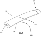
- Fig. 4 shows a perspective view of an embodiment of the device 102 engaged with the component 104 at the upper end 108.
- the device 102 includes a charging connection 115 at the lower end 110.
- the front surface 201 of the device body 200 is curved in the transverse dimension.
- the rear surface 202 of the device body 200 is curved in the transverse dimension.
- the curvatures of the front surface 201 and rear surface 202 are of the opposite sense to one another.
- Both front and rear surfaces 201, 202 are convex in the transverse dimension. This leads to a mandorla-/lemon-/eye-shaped cross sectional shape of the device body 200.
- the front surface 201 and rear surface 202 meet at two transverse edges 205.
- the transverse edges 205 have a radius of curvature that is significantly smaller than the radius of curvature of either the front 201 or rear surface 202. This leads to the transverse edges being substantially “pointed” or “sharp".
- the transverse edges may have a radius of curvature in the transverse dimension of less than 1 millimetre.
- the transverse edges 205 extend substantially the full longitudinal length of the device body 200.
- the front surface 201 of the device body 200 may include visual user feedback means.
- Fig. 5 illustrates a schematic transverse cross section through the device 102 of Fig. 4 , in accordance with an embodiment.
- the front surface 201 and rear surface 202 are shown meeting at the transverse edges 205 on either side of the device body 200.
- the radius of curvature in the transverse dimension of the front surface 201 is equal to the radius of curvature in the transverse dimension of the rear surface 202.
- the radius of curvature of the front surface 201 may be between 10 and 15 mm.
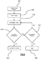
- Fig. 6 is a flow chart illustrating general operation of a controller of a smoking substitute device (such that described above).
- the controller receives a movement signal from a movement sensor of the device.
- the movement signal is indicative of movement of the device and may, for example, be a general movement of the device, or a specific movement (such as that experience in response to e.g. 3 taps on the device by a user).
- the controller determines whether the time period since a previous user interaction exceeds a threshold time period (stored in a memory of the device). If the time period does exceed the threshold, then that is indicative that the device is not being used by a user.
- the controller determines (at block 302) that time period exceeds the threshold, then at block 304, the controller transmits a feedback signal to a user feedback element (including e.g. haptic feedback generators, LEDs and/or a display screen) of the device.
- a user feedback element including e.g. haptic feedback generators, LEDs and/or a display screen
- the feedback signal may be based on or representative of an operating characteristic (e.g. battery charge) of the device.
- the controller may not provide a feedback signal (and may simply end the current sequence).
- Fig. 7 and Fig. 8 illustrate two different ways in which the controller of the device may assess whether the time period since the previous user interaction (represented by an interaction signal) has exceeded a predetermined threshold time period.
- the controller receives an interaction signal from a sensor of the device (i.e. indicative of interaction with the device).
- the interaction may be an inhalation, movement and/or connection to an external power source.
- the controller starts a timer and, at block 310, increments the timer.
- the controller checks whether a movement signal has been received. The movement signal is received from a movement sensor of the device. If no movement signal has been received, then the controller increments the timer and checks again whether a movement signal has been received. This process continues (in a repeated manner) until the controller receives a movement signal.
- the controller When the controller does receive the movement signal, it compares, at block 314, the value of the timer (being indicative of the time period since the interaction signal) with a predetermined threshold value. If the value of the timer is greater than the threshold value then the controller deems the device to be in an idle state and proceeds, at block 304, by transmitting a feedback signal to the user feedback element of the device. On the other hand, if the value does not exceed the threshold value then at block 306, the controller ends the sequence.
- the value of the timer being indicative of the time period since the interaction signal
- FIG. 8 A variation of this control method is shown in Fig. 8 .
- the controller again receives an interaction signal (from a sensor of the device) at block 300, starts a timer at block 308 and increments the timer at block 310.
- the controller checks (at block 314) whether the increment of the timer has caused the value of the timer to exceed a predetermined threshold value (stored in a memory of the device). If the timer value does not exceed the threshold value, then the controller, at block 312, checks whether a movement signal has been received. If a movement signal is received then the controller ends the sequence at block 306. If, on the other hand, a movement signal has not been received, then the controller returns to block 310 and once again increments the timer.
- the controller determines that the incremented timer value exceeds the threshold, at block 316, the controller stores (in a memory of the device) an indication that the device is in an idle state.
- the controller checks the memory for the stored state of the device. If the stored state is an idle state, then the controller transmits a feedback signal to a user feedback element of the device (i.e. for indication/communication to a user by the user feedback element).
Abstract
The present disclosure relates to an aerosol delivery device and system e.g. a smoking substitute device and system. In particular, an aerosol delivery device comprises a movement sensor configured to detect movement of the device and transmit movement signals indicative of movement of the device and a user feedback element configured to receive feedback signals and provide feedback to a user in response to the feedback signals. The device further comprises a controller configured to receive a movement signal from the movement sensor, determine whether a time period since a previous user interaction with the device exceeds a threshold time period, and provide a feedback signal to the user feedback element if the time period exceeds the threshold time period.
Description
- The present disclosure relates to an aerosol delivery device and an aerosol delivery system such as a smoking substitute device/system.
- The smoking of tobacco is generally considered to expose a smoker to potentially harmful substances. It is generally thought that a significant amount of the potentially harmful substances are generated through the heat caused by the burning and/or combustion of the tobacco and the constituents of the burnt tobacco in the tobacco smoke itself.
- Combustion of organic material such as tobacco is known to produce tar and other potentially harmful by-products. There have been proposed various smoking substitute systems in order to avoid the smoking of tobacco.
- Such smoking substitute systems can form part of nicotine replacement therapies aimed at people who wish to stop smoking and overcome a dependence on nicotine.
- Smoking substitute systems, which may also be known as electronic nicotine delivery systems, may comprise electronic systems that permit a user to simulate the act of smoking by producing an aerosol, also referred to as a "vapour", which is drawn into the lungs through the mouth (inhaled) and then exhaled. The inhaled aerosol typically bears nicotine and/or flavourings without, or with fewer of, the odour and health risks associated with traditional smoking.
- In general, smoking substitute systems are intended to provide a substitute for the rituals of smoking, whilst providing the user with a similar experience and satisfaction to those experienced with traditional smoking and tobacco products.
- The popularity and use of smoking substitute systems has grown rapidly in the past few years. Although originally marketed as an aid to assist habitual smokers wishing to quit tobacco smoking, consumers are increasingly viewing smoking substitute systems as desirable lifestyle accessories. Some smoking substitute systems are designed to resemble a traditional cigarette and are cylindrical in form with a mouthpiece at one end. Other smoking substitute systems do not generally resemble a cigarette (for example, the smoking substitute device may have a generally box-like form).
- There are a number of different categories of smoking substitute systems, each utilising a different smoking substitute approach. A smoking substitute approach corresponds to the manner in which the substitute system operates for a user.
- One approach for a smoking substitute system is the so-called "vaping" approach, in which a vaporisable liquid, typically referred to (and referred to herein) as "e-liquid", is heated by a heater to produce an aerosol vapour which is inhaled by a user. An e-liquid typically includes a base liquid as well as nicotine and/or flavourings. The resulting vapour therefore typically contains nicotine and/or flavourings. The base liquid may include propylene glycol and/or vegetable glycerine.
- A typical vaping smoking substitute system includes a mouthpiece, a power source (typically a battery), a tank or liquid reservoir for containing e-liquid, as well as a heater. In use, electrical energy is supplied from the power source to the heater, which heats the e-liquid to produce an aerosol (or "vapour") which is inhaled by a user through the mouthpiece.
- Vaping smoking substitute systems can be configured in a variety of ways. For example, there are "closed system" vaping smoking substitute systems which typically have a heater and a sealed tank which is pre-filled with e-liquid and is not intended to be refilled by an end user. One subset of closed system vaping smoking substitute systems include a device which includes the power source, wherein the device is configured to be physically and electrically coupled to a component including the tank and the heater. In this way, when the tank of a component has been emptied, the device can be reused by connecting it to a new component. Another subset of closed system vaping smoking substitute systems are completely disposable, and intended for one-use only.
- There are also "open system" vaping smoking substitute systems which typically have a tank that is configured to be refilled by a user, so the system can be used multiple times.
- An example vaping smoking substitute system is the myblu™ e-cigarette. The myblu™ e cigarette is a closed system which includes a device and a consumable component. The device and consumable component are physically and electrically coupled together by pushing the consumable component into the device. The device includes a rechargeable battery. The consumable component includes a mouthpiece, a sealed tank which contains e-liquid, as well as a vaporiser, which for this system is a heating filament coiled around a portion of a wick which is partially immersed in the e-liquid. The system is activated when a microprocessor on board the device detects a user inhaling through the mouthpiece. When the system is activated, electrical energy is supplied from the power source to the vaporiser, which heats e-liquid from the tank to produce a vapour which is inhaled by a user through the mouthpiece.
- Another example vaping smoking substitute system is the blu PRO™ e-cigarette. The blu PRO™ e cigarette is an open system which includes a device, a (refillable) tank, and a mouthpiece. The device and tank are physically and electrically coupled together by screwing one to the other. The mouthpiece and refillable tank are physically coupled together by screwing one into the other, and detaching the mouthpiece from the refillable tank allows the tank to be refilled with e-liquid. The system is activated by a button on the device. When the system is activated, electrical energy is supplied from the power source to a vaporiser, which heats e-liquid from the tank to produce a vapour which is inhaled by a user through the mouthpiece.
- An alternative to the "vaping" approach is the so-called Heated Tobacco ("HT") approach in which tobacco (rather than an e-liquid) is heated or warmed to release vapour. HT is also known as "heat not burn" ("HNB"). The tobacco may be leaf tobacco or reconstituted tobacco. In the HT approach the intention is that the tobacco is heated but not burned, i.e. the tobacco does not undergo combustion.
- The heating, as opposed to burning, of the tobacco material is believed to cause fewer, or smaller quantities, of the more harmful compounds ordinarily produced during smoking. Consequently, the HT approach may reduce the odour and/or health risks that can arise through the burning, combustion and pyrolytic degradation of tobacco.
- A typical HT smoking substitute system may include a device and a consumable component. The consumable component may include the tobacco material. The device and consumable component may be configured to be physically coupled together. In use, heat may be imparted to the tobacco material by a heating element of the device, wherein airflow through the tobacco material causes components in the tobacco material to be released as vapour. A vapour may also be formed from a carrier in the tobacco material (this carrier may for example include propylene glycol and/or vegetable glycerine) and additionally volatile compounds released from the tobacco. The released vapour may be entrained in the airflow drawn through the tobacco.
- As the vapour passes through the consumable component (entrained in the airflow) from the location of vaporization to an outlet of the component (e.g. a mouthpiece), the vapour cools and condenses to form an aerosol for inhalation by the user. The aerosol may contain nicotine and/or flavour compounds.
- Some smoking substitute devices include a user interface (e.g. LED) for conveying information about the device to a user (e.g. a power status of the device). However, continued activation/operation of the user interface can result in unnecessary power usage of the device (which can in turn result in faster depletion of the battery of the device).
- Accordingly, there is a need for an improved aerosol delivery device/system which addresses at least some of the problems of the known devices and systems.
- According to a first aspect, there is provided an aerosol delivery device (e.g. a smoking substitute device) comprising:
- a movement sensor configured to detect movement of the device and transmit movement signals indicative of movement of the device;
- a user feedback element configured to receive feedback signals and provide feedback to a user in response to the feedback signals; and
- a controller configured to receive a movement signal from the movement sensor, determine whether a time period since a previous user interaction with the device exceeds a threshold
- time period, and provide a feedback signal to the user feedback element if the time period exceeds the threshold time period.
- Thus, such an arrangement may allow the user feedback element to react suitably to periods where the device is in an idle state during a period of inactivity (i.e. is not being used by the user). During such periods, it may be desirable to minimise activation of the user feedback element in order to reduce power consumption. Thus, the provision of a feedback signal to the user feedback element upon detection of movement of the device (i.e. after a period of inactivity) may mean that the user feedback element is only activated when the user is using the device. This may help to reduce unnecessary power consumption by the device.
- Optional features will now be set out. These are applicable singly or in any combination with any aspect.
- The controller may be configured to receive a user interaction signal from a component of the device in orderto determine that a user interaction has occurred (i.e. so as to be able to determine the time period since the previous user interaction). That is, the previous user interaction may be determined from a previous user interaction signal received by the controller. In other words, the controller may receive an interaction signal and then subsequently receive the movement signal and determine the time period between the two signals (for comparison with the threshold time period).
- The user interaction signal may be indicative of the device being connected to an external power source (for e.g. recharging a battery of the device) and the interaction signal may be received from a charging connector (for connecting the device to an external power source). In this respect, the time period may be between the connection of the device to the external power source and a subsequent movement of the device.
- The user interaction signal may be indicative of an inhalation (i.e. puff) from the device by a user. Thus, the device may comprise an airflow (i.e. puff) sensor that detects inhalation and the user interaction signal may be at least partly provided by the airflow sensor. In such embodiments, the time period may thus be between an inhalation and a subsequent movement of the device.
- The user interaction may be indicative of movement of the device. In this case, the time period may be determined by the controller based on the time difference between two (i.e. consecutive) signals received from the movement sensor.
- In some embodiments, the user interaction signal may be any one of a signal indicative of connection to an external power source, a signal indicative of inhalation and a signal indicative of movement of the device. In otherwords, in one embodiment, a detection of any one of charging, movement or inhalation can initiate the time period that the controller compares against the threshold time period.
- The threshold time period may be stored in a memory of the device (to which the controller is operatively connected). The threshold time period may, for example, be greater than 10 seconds, or e.g. greater than 30, 60, 120 or 240 seconds.
- To determine the time period between the interaction signal and the movement signal, the controller may be configured to initiate a timer upon receipt of the interaction signal. The controller may terminate the timer upon receipt of the movement signal. Alternatively, the controller may generate a first timestamp (e.g. and store the timestamp in the memory) on receipt of the interaction signal and a second timestamp on receipt of the movement signal (i.e. the difference between the timestamps providing an indication of the time period).
- In other embodiments, the controller may initiate a timer on receipt of the interaction signal and, in response to the timer exceeding the threshold time period, may store (i.e. in the memory of the device) an indication that the device has entered an idle state. Upon receipt of a subsequent movement signal, the controller may retrieve the state of the device from the memory and, if the stored state indicates that the device is in an idle state, may accordingly provide a feedback signal to the user feedback element.
- The movement sensor may be an accelerometer, for detecting movement of the device. Where, the user interaction is (or comprises) movement of the device, the movement may be any movement of the device, or a specific movement (or motion) of the device by a user. In other words, the user interaction signal may be indicative of a specific movement of the device. In one embodiment, the specific movement may be one or more taps (by a user) on the device. The controller may be configured to determine whether the user interaction signal received from the sensor is indicative of the specific movement (e.g. tapping) of the device and only provide a feedback signal upon determination that the detected movement matches the specific movement. For example, the memory of the device may comprise a database of specific movement signals and, upon receipt of the interaction signal, the controller may interrogate the database in order to determine whether the received interaction signal matches a specific movement signal in the database.
- The user feedback element may comprise a haptic feedback generation unit (e.g. an electric motor and a weight mounted eccentrically on a shaft of the electric motor). Thus, the feedback signal may be received from the controller by the haptic feedback generation unit and the haptic feedback generation unit may generate haptic feedback in response to the feedback signal. In this respect, the feedback signal may be representative of a haptic feedback (vibration) pattern. Thus, for example, haptic feedback may be provided upon movement of the device by a user when the device is an idle state, which may indicate to the user that the device is operational and that e.g. a battery of the device is not fully discharged. This provides a convenient, low-power, way in which to communicate such information to a user. For example, this may mean there is no need to have a display or LED that remains active even when the device is not being used (which would be detrimental to battery life).
- The user feedback element may comprise visual user feedback means, for example one or more lights (e.g. LEDs) and/or a display screen. Thus, for example, the one or more lights may receive the feedback signal and illuminate accordingly (i.e. in response to user interaction when the device is in an idle state).
- The controller may be configured to provide a feedback signal that is indicative of an operating characteristic of the device. The device may comprises a source of power which may be a battery (e.g. a rechargeable battery). The source of power may be a capacitor. The operating characteristic of the device (indicated by the feedback signal) may be a charge level of the battery. In other words, user feedback element may, in response to user interaction when the device is in an idle state, communicate the battery charge level of the battery.
- Where the feedback signal is received by a haptic feedback generation unit, this communication may be, for example, by way of a particular haptic feedback (vibration) pattern dependant on the level of charge. Where the feedback signal is received by one or more LEDs of the device, the battery level may be communicated, for example, by the brightness or colour of the LEDs, or the number of LEDs that are illuminated (where the device comprises a plurality of LEDs).
- In one example, the user feedback element may comprise an LED and the feedback signal provided to the LED may be representative of a charge level of a battery of the device. For example, the controller may control the LED (i.e. via the provision of the feedback signal) so as to illuminate with a particular colour and/or brightness depending on the current charge level of the battery of the device.
- The device may comprise a device body for housing the power source and/or other electrical components (e.g. sensors, controller, etc.). The device body may be an elongate body i.e. with a greater length than depth/width. It may have a greater width than depth.
- The device body may have a length of between 5 and 30 cm e.g. between 10 and 20 cm such as between 10 and 13 cm. The maximum depth of the device body may be between 5 and 30 mm e.g. between 10 and 20 mm.
- The device body may have a front surface that is curved in the transverse dimension. The device body may have a rear surface that is curved in the transverse dimension. The curvatures of the front surface and rear surface may be of the opposite sense to one another. Both front and rear surfaces may be convex in the transverse dimension. They may have an equal radius of curvature.
- The radius of curvature of the front surface may be between 10 and 50 mm, preferably between 10 and 40 mm, preferably between 10 and 30 mm, preferably been 10 and 20 mm, more preferably between 10 and 15 mm, more preferably substantially 13.5 mm.
- The front and rear surfaces may meet at opposing transverse edges of the device body. This leads to a mandorla-/lemon-/eye-shaped cross sectional shape of the device body.
- The transverse edges may have a radius of curvature that is significantly smaller than the radius of curvature of either the front or rear surface. This leads to the transverse edges being substantially "pointed" or "sharp". The transverse edges may have a radius of curvature in the transverse dimension of less than 10 mm, preferably less than 5 mm, preferably less than 2 mm, preferably less than 1 mm.
- The transverse edges may extend substantially the full longitudinal length of the device body. However, in some embodiments, the transverse edges may only extend along a longitudinal portion of the device body.
- The device body may have a curved longitudinal axis i.e. curved in a direction between the front and rear faces.
- The front and/or rear surface of the device body may include the visual user feedback means, for example the one or more lights e.g. one or more LEDs.
- In some embodiments, the device body may include an illumination region configured to allow light provided by a light source (e.g. one or more LEDs) within the device body to shine through.
- As mentioned above, a memory may be provided and may be operatively connected to the controller. The memory may include non-volatile memory. The memory may include instructions which, when implemented, cause the controller to perform certain tasks or steps of a method. The device may comprise a wireless interface, which may be configured to communicate wirelessly with another device, for example a mobile device, e.g. via Bluetooth®. To this end, the wireless interface could include a Bluetooth® antenna. Other wireless communication interfaces, e.g. WiFi®, are also possible. The wireless interface may also be configured to communicate wirelessly with a remote server.
- As also mentioned above, an airflow (i.e. puff) sensor may be provided that is configured to detect a puff (i.e. inhalation from a user). The airflow sensor may be operatively connected to the controller so as to be able to provide a signal to the controller that is indicative of a puff state (i.e. puffing or not puffing). The airflow sensor may, for example, be in the form of a pressure sensor or an acoustic sensor. The controller may control power supply to a heating element in response to airflow detection by the sensor. The control may be in the form of activation of the heating element in response to a detected airflow. The airflow sensor may form part of the device. The heating element may be used in a vaporiser to vaporise an aerosol precursor. The vaporiser may be housed in a vaporising chamber.
- In a second aspect, there is provided a smoking substitute system comprising a device according to the first aspect and a component for containing an aerosol precursor.
- The component may be an aerosol-delivery (e.g. a smoking substitute) consumable i.e. in some embodiments the component may be a consumable component for engagement with the aerosol-delivery (e.g. a smoking substitute) device to form the aerosol-delivery (e.g. smoking substitute) system.
- The device may be configured to receive the consumable component. The device and the consumable component may be configured to be physically coupled together. For example, the consumable component may be at least partially received in a recess of the device, such that there is snap engagement between the device and the consumable component. Alternatively, the device and the consumable component may be physically coupled together by screwing one onto the other, or through a bayonet fitting.
- Thus, the consumable component may comprise one or more engagement portions for engaging with the device.
- The consumable component may comprise an electrical interface for interfacing with a corresponding electrical interface of the device. One or both of the electrical interfaces may include one or more electrical contacts (which may extend through the transverse plate of the lower portion of the insert). Thus, when the device is engaged with the consumable component, the electrical interface may be configured to transfer electrical power from the power source to a heating element of the consumable component. The electrical interface may also be used to identify the consumable component from a list of known types. The electrical interface may additionally or alternatively be used to identify when the consumable component is connected to the device.
- The device may alternatively or additionally be able to detect information about the consumable component via an RFID reader, a barcode or QR code reader. This interface may be able to identify a characteristic (e.g. a type) of the consumable. In this respect, the consumable component may include any one or more of an RFID chip, a barcode or QR code, or memory within which is an identifier and which can be interrogated via the interface.
- In other embodiments, the component may be integrally formed with the aerosol-delivery (e.g. a smoking substitute) device to form the aerosol-delivery (e.g. s smoking substitute) system.
- In such embodiments, the aerosol former (e.g. e-liquid) may be replenished by re-filling a tank that is integral with the device (rather than replacing the consumable). Access to the tank (for re-filling of the e-liquid) may be provided via e.g. an opening to the tank that is sealable with a closure (e.g. a cap).
- The smoking substitute system may comprise an airflow path therethrough, the airflow path extending from an air inlet to an outlet. The outlet may be at a mouthpiece portion of the component. In this respect, a user may draw fluid (e.g. air) into and along the airflow path by inhaling at the outlet (i.e. using the mouthpiece).
- The airflow path passes the vaporiser between the air inlet to the air outlet.
- The airflow path may comprise a first portion extending from the air inlet towards the vaporiser. The second portion of the airflow path passes through the vaporising chamber to a conduit that extends to the air outlet. The conduit may extend along the axial centre of the component.
- References to "downstream" in relation to the airflow path are intended to refer to the direction towards the air outlet/outlet portion. Thus the second and third portions of the airflow path are downstream of the first portion of the airflow path. Conversely, references to "upstream" are intended to refer to the direction towards the air inlet. Thus the first portion of the airflow path (and the air inlet) is upstream of the second/third portions of the airflow path (and the air outlet/outlet portion).
- References to "upper", "lower", "above" or "below" are intended to refer to the component when in an upright/vertical orientation i.e. with elongate (longitudinal/length) axis of the component vertically aligned and with the mouthpiece vertically uppermost.
- The component may comprise a tank for housing the aerosol precursor (e.g. a liquid aerosol precursor). The aerosol precursor may comprise an e-liquid, for example, comprising a base liquid and e.g. nicotine. The base liquid may include propylene glycol and/or vegetable glycerine.
- At least a portion of one of the walls defining the tank may be translucent or transparent.
- The conduit may extend through the tank with the conduit walls defining an inner region of the tank. In this respect, the tank may surround the conduit e.g. the tank may be annular.
- As discussed above, the air flow path passes the vaporiser between the air inlet to the air outlet. The vaporiser may comprise a wick e.g. an elongate wick which may have a cylindrical shape.
- The wick may be oriented so as to extend in the direction of the width dimension of the component (perpendicular to the longitudinal axis of the component). Thus the wick may extend in a direction perpendicular to the direction of airflow in the airflow path.
- The vaporiser may be disposed in the vaporising chamber. The vaporising chamber may form part of the airflow path.
- The wick may comprise a porous material. A portion of the wick may be exposed to airflow in the airflow path. The wick may also comprise one or more portions in contact with liquid aerosol precursor stored in the tank. For example, opposing ends of the wick may protrude into the tank and a central portion (between the ends) may extend across the airflow path so as to be exposed to airflow. Thus, fluid may be drawn (e.g. by capillary action) along the wick, from the tank to the exposed portion of the wick.
- The heating element may be in the form of a filament wound about the wick (e.g. the filament may extend helically about the wick). The filament may be wound about the exposed portion of the wick. The heating element is electrically connected (or connectable) to the power source. Thus, in operation, the power source may supply electricity to (i.e. apply a voltage across) the heating element so as to heat the heating element. This may cause liquid stored in the wick (i.e. drawn from the tank) to be heated so as to form a vapour and become entrained in airflow along the airflow path. This vapour may subsequently cool to form an aerosol e.g. in the conduit.
- In a third aspect there is provided a method of using the aerosol-delivery (e.g. smoking substitute) system according to the second aspect, the method comprising engaging the consumable component with an aerosol-delivery (e.g. smoking substitute) device (as described above) having a power source so as to electrically connect the power source to the consumable component (i.e. to the vaporiser of the consumable component).
- According to a fourth aspect, there is provided a method of controlling an aerosol delivery device (e.g. a smoking substitute device), the method comprising:
- detecting movement of the device;
- upon detection of the movement, determining whether a time period since a previous user interaction with the device exceeds a threshold time period; and
- providing a feedback signal to a user feedback element of the device for feedback to a user, if the time period exceeds the threshold period.
- The method may comprise detecting the previous user interaction. The previous user interaction may be one or more of movement of the device, connection of the device to an external power source and inhalation through the device by a user.
- The method may further comprise determining an operating characteristic of the device upon receipt of the movement signal. The operating characteristic may be a battery charge level of a battery of the device. The feedback signal may be indicative of the operating characteristic (e.g. battery charge level) of the device.
- The invention includes the combination of the aspects and preferred features described except where such a combination is clearly impermissible or expressly avoided.
- So that further aspects and features thereof may be appreciated, embodiments will now be discussed in further detail with reference to the accompanying figures, in which:
-
Fig. 1A is a front schematic view of a smoking substitute system; -
Fig. 1B is a front schematic view of a device of the system; -
Fig. 1C is a front schematic view of a component of the system; -
Fig. 2A is a schematic of the components of the device; -
Fig. 2B is a schematic of the components of the component; -
Fig. 3 is a section view of the component; -
Fig. 4 is a perspective view of a variation of the substitute smoking system; -
Fig. 5 is a section view of the device of the system ofFig. 4 ; -
Fig. 6 is a flow chart illustrating operation of a controller of a smoking substitute device; -
Fig. 7 is a flow chart illustrating a method of determining whether a smoking substitute device is in an idle state; and -
Fig. 8 is a flow chart illustrating a variation of the method ofFig. 7 . - Aspects and embodiments will now be discussed with reference to the accompanying figures. Further aspects and embodiments will be apparent to those skilled in the art.
-
Fig. 1A shows a first embodiment of asmoking substitute system 100. In this example, thesmoking substitute system 100 includes adevice 102 and acomponent 104. Thecomponent 104 may alternatively be referred to as a "pod", "cartridge" or "cartomizer". It should be appreciated that in other examples (i.e. open systems), the device may be integral with the component. In such systems, a tank of the aerosol delivery system may be accessible for refilling the device. - In this example, the
smoking substitute system 100 is a closed system vaping system, wherein thecomponent 104 includes a sealedtank 106 and is intended for single-use only. Thecomponent 104 is removably engageable with the device 102 (i.e. for removal and replacement).Fig. 1A shows thesmoking substitute system 100 with thedevice 102 physically coupled to thecomponent 104,Fig. 1B shows thedevice 102 of thesmoking substitute system 100 without thecomponent 104, andFig. 1C shows thecomponent 104 of thesmoking substitute system 100 without thedevice 102. - The
device 102 and thecomponent 104 are configured to be physically coupled together by pushing thecomponent 104 into a cavity at anupper end 108 of thedevice 102, such that there is an interference fit between thedevice 102 and thecomponent 104. In other examples, thedevice 102 and the component may be coupled by screwing one onto the other, or through a bayonet fitting. - The
component 104 includes a mouthpiece (not shown inFig. 1A, 1B or 1C ) at anupper end 109 of thecomponent 104, and one or more air inlets (not shown) in fluid communication with the mouthpiece such that air can be drawn into and through thecomponent 104 when a user inhales through the mouthpiece. Thetank 106 containing e-liquid is located at thelower end 111 of thecomponent 104. - The
tank 106 includes awindow 112, which allows the amount of e-liquid in thetank 106 to be visually assessed. Thedevice 102 includes aslot 114 so that thewindow 112 of thecomponent 104 can be seen whilst the rest of thetank 106 is obscured from view when thecomponent 104 is inserted into the cavity at theupper end 108 of thedevice 102. - The
lower end 110 of thedevice 102 also includes a light 116 (e.g. an LED) located behind a small translucent cover. The light 116 may be configured to illuminate when thesmoking substitute system 100 is activated. Whilst not shown, thecomponent 104 may identify itself to thedevice 102, via an electrical interface, RFID chip, or barcode. - The
lower end 110 of thedevice 102 also includes acharging connection 115, which is usable to charge a battery within thedevice 102. Thecharging connection 115 can also be used to transfer data to and from the device, for example to update firmware thereon. -
Figs. 2A and 2B are schematic drawings of thedevice 102 andcomponent 104. As is apparent fromFig. 2A , thedevice 102 includes apower source 118, acontroller 120, amemory 122, awireless interface 124, anelectrical interface 126, auser feedback element 160,sensors 162 and, optionally, one or moreadditional components 128. - The
power source 118 is preferably a battery, more preferably a rechargeable battery. Thecontroller 120 may include a microprocessor, for example. Thememory 122 preferably includes non-volatile memory. The memory may include instructions which, when implemented, cause thecontroller 120 to perform certain tasks or steps of a method. - The
wireless interface 124 is preferably configured to communicate wirelessly with another device, for example a mobile device, e.g. via Bluetooth®. To this end, thewireless interface 124 could include a Bluetooth® antenna. Other wireless communication interfaces, e.g. WiFi®, are also possible. Thewireless interface 124 may also be configured to communicate wirelessly with a remote server. - The
electrical interface 126 of thedevice 102 may include one or more electrical contacts. Theelectrical interface 126 may be located in a base of the aperture in theupper end 108 of thedevice 102. When thedevice 102 is physically coupled to thecomponent 104, theelectrical interface 126 is configured to transfer electrical power from thepower source 118 to the component 104 (i.e. upon activation of the smoking substitute system 100). - The
electrical interface 126 may also be used to identify thecomponent 104 from a list of known components. For example, thecomponent 104 may be a particular flavour and/or have a certain concentration of nicotine (which may be identified by the electrical interface 126). This can be indicated to thecontroller 120 of thedevice 102 when thecomponent 104 is connected to thedevice 102. Additionally, or alternatively, there may be a separate communication interface provided in thedevice 102 and a corresponding communication interface in thecomponent 104 such that, when connected, thecomponent 104 can identify itself to thedevice 102. - The
user feedback element 160 of thedevice 102 may comprise the light 116 discussed above. Theuser feedback element 160 may additionally, or alternatively, comprise a haptic feedback generator, a plurality of LEDs and/or a display screen. - The
additional components 128 of thedevice 102 also comprises thecharging connection 115 configured to receive power from the charging station (i.e. when thepower source 118 is a rechargeable battery). This may be located at thelower end 110 of thedevice 102. - The
additional components 128 of thedevice 102 may, if thepower source 118 is a rechargeable battery, include a battery charging control circuit, for controlling (and detecting) the charging of the rechargeable battery. However, a battery charging control circuit could equally be located in the charging station (if present). - The
sensors 162 may include e.g. an airflow (i.e. puff) sensor for detecting airflow in thesmoking substitute system 100, e.g. caused by a user inhaling through amouthpiece 136 of thecomponent 104. Thesmoking substitute system 100 may be configured to be activated when airflow is detected by the airflow sensor. The airflow sensor can be used to determine, for example, how heavily a user draws on the mouthpiece or how many times a user draws on the mouthpiece in a particular time period. Thesensors 162 additionally comprises a movement sensor. One or more of thesensors 162 may alternatively be included in thecomponent 104. - The
controller 120 may be configured to receive a movement signal from the movement sensor, and in response, determine whether a time period since a previous user interaction with the device exceeds a predetermined threshold time period (stored in the memory 122). Thecontroller 120 may respond/react to a movement signal indicative of any movement of thedevice 102, or may respond only to movement signals indicative of specific movements of thedevice 102. - The previous user interaction with the device may be a movement of the device (detected by the movement sensor), a connection of the device to an external power source, and/or an inhalation (detected by the airflow sensor).
- If the time period since the previous user interaction does exceed the predetermined threshold time period, then the controller is configured to transmit a feedback signal to the user feedback element 160 (e.g. for communication via the LEDs, display screen, or haptic feedback generator.
- The feedback signal may, for example, be a current battery charge level (of the power source 118).
- The
additional components 128 of thedevice 102 may include a user input, e.g. a button. Thesmoking substitute system 100 may be configured to be activated when a user interacts with the user input (e.g. presses the button). This provides an alternative to the airflow sensor as a mechanism for activating thesmoking substitute system 100. - As shown in
Fig. 2B , thecomponent 104 includes thetank 106, anelectrical interface 130, avaporiser 132, one ormore air inlets 134, amouthpiece 136, and one or moreadditional components 138. - The
electrical interface 130 of thecomponent 104 may include one or more electrical contacts. Theelectrical interface 126 of thedevice 102 and anelectrical interface 130 of thecomponent 104 are configured to contact each other and thereby electrically couple thedevice 102 to thecomponent 104 when thelower end 111 of thecomponent 104 is inserted into theupper end 108 of the device 102 (as shown inFig. 1A ). In this way, electrical energy (e.g. in the form of an electrical current) is able to be supplied from thepower source 118 in thedevice 102 to thevaporiser 132 in thecomponent 104. - The
vaporiser 132 is configured to heat and vaporise e-liquid contained in thetank 106 using electrical energy supplied from thepower source 118. As will be described further below, thevaporiser 132 includes a heating filament and a wick. The wick draws e-liquid from thetank 106 and the heating filament heats the e-liquid to vaporise the e-liquid. - The one or
more air inlets 134 are preferably configured to allow air to be drawn into thesmoking substitute system 100, when a user inhales through themouthpiece 136. When thecomponent 104 is physically coupled to thedevice 102, theair inlets 134 receive air, which flows to theair inlets 134 along a gap between thedevice 102 and thelower end 111 of thecomponent 104. - In operation, a user activates the
smoking substitute system 100, e.g. through interaction with a user input forming part of thedevice 102 or by inhaling through themouthpiece 136 as described above. Upon activation, thecontroller 120 may supply electrical energy from thepower source 118 to the vaporiser 132 (viaelectrical interfaces 126, 130), which may cause thevaporiser 132 to heat e-liquid drawn from thetank 106 to produce a vapour which is inhaled by a user through themouthpiece 136. - An example of one of the one or more
additional components 138 of thecomponent 104 is an interface for obtaining an identifier of thecomponent 104. As discussed above, this interface may be, for example, an RFID reader, a barcode, a QR code reader, or an electronic interface which is able to identify the component. Thecomponent 104 may, therefore include any one or more of an RFID chip, a barcode or QR code, or memory within which is an identifier and which can be interrogated via the electronic interface in thedevice 102. - It should be appreciated that the
smoking substitute system 100 shown infigures 1A to 2B is just one exemplary implementation of a smoking substitute system. For example, the system could otherwise be in the form of an entirely disposable (single-use) system or an open system in which the tank is refillable (rather than replaceable). -
Fig. 3 is a section view of thecomponent 104 described above. Thecomponent 104 comprises atank 106 for storing e-liquid, amouthpiece 136 and aconduit 140 extending along a longitudinal axis of thecomponent 104. In the illustrated embodiment theconduit 140 is in the form of a tube having a substantially circular transverse cross-section (i.e. transverse to the longitudinal axis). Thetank 106 surrounds theconduit 140, such that theconduit 140 extends centrally through thetank 106. - A
tank housing 142 of thetank 106 defines an outer casing of thecomponent 104, whilst aconduit wall 144 defines theconduit 140. Thetank housing 142 extends from thelower end 111 of thecomponent 104 to themouthpiece 136 at theupper end 109 of thecomponent 104. At the junction between themouthpiece 136 and thetank housing 142, themouthpiece 136 is wider than thetank housing 142, so as to define alip 146 that overhangs thetank housing 142. Thislip 146 acts as a stop feature when thecomponent 104 is inserted into the device 102 (i.e. by contact with an upper edge of the device 102). - The
tank 106, theconduit 140 and themouthpiece 136 are integrally formed with each other so as to form a single unitary component and may e.g. be formed by way of an injection moulding process. Such a component may be formed of a thermoplastic material such as polypropylene. - The
mouthpiece 136 comprises amouthpiece aperture 148 defining an outlet of theconduit 140. Thevaporiser 132 is fluidly connected to themouthpiece aperture 148 and is located in a vaporisingchamber 156 of thecomponent 104. The vaporisingchamber 156 is downstream of theinlet 134 of thecomponent 104 and is fluidly connected to the mouthpiece aperture 148 (i.e. outlet) by theconduit 140. - The
vaporiser 132 comprises aporous wick 150 and aheater filament 152 coiled around theporous wick 150. Thewick 150 extends transversely across the chamber vaporising 156 between sidewalls of thechamber 156 which form part of aninner sleeve 154 of aninsert 158 that defines thelower end 111 of thecomponent 104 that connects with thedevice 102. Theinsert 158 is inserted into an open lower end of thetank 106 so as to seal against thetank housing 142. - In this way, the
inner sleeve 154 projects into thetank 106 and seals with the conduit 140 (around the conduit wall 144) so as to separate the vaporisingchamber 156 from the e-liquid in thetank 106. Ends of thewick 150 project through apertures in theinner sleeve 154 and into thetank 106 so as to be in contact with the e-liquid in thetank 106. In this way, e-liquid is transported along the wick 150 (e.g. by capillary action) to a central portion of thewick 150 that is exposed to airflow through the vaporisingchamber 156. The transported e-liquid is heated by the heater filament 152 (when activated e.g. by detection of inhalation), which causes the e-liquid to be vaporised and to be entrained in air flowing past thewick 150. This vaporised liquid may cool to form an aerosol in theconduit 140, which may then be inhaled by a user. -
Fig. 4 shows a perspective view of an embodiment of thedevice 102 engaged with thecomponent 104 at theupper end 108. Thedevice 102 includes acharging connection 115 at thelower end 110. - The
front surface 201 of thedevice body 200 is curved in the transverse dimension. Therear surface 202 of thedevice body 200 is curved in the transverse dimension. The curvatures of thefront surface 201 andrear surface 202 are of the opposite sense to one another. Both front andrear surfaces device body 200. - The
front surface 201 andrear surface 202 meet at twotransverse edges 205. Thetransverse edges 205 have a radius of curvature that is significantly smaller than the radius of curvature of either the front 201 orrear surface 202. This leads to the transverse edges being substantially "pointed" or "sharp". The transverse edges may have a radius of curvature in the transverse dimension of less than 1 millimetre. - As illustrated in
Fig. 4 , thetransverse edges 205 extend substantially the full longitudinal length of thedevice body 200. - The
front surface 201 of thedevice body 200 may include visual user feedback means. -
Fig. 5 illustrates a schematic transverse cross section through thedevice 102 ofFig. 4 , in accordance with an embodiment. Thefront surface 201 andrear surface 202 are shown meeting at thetransverse edges 205 on either side of thedevice body 200. The radius of curvature in the transverse dimension of thefront surface 201 is equal to the radius of curvature in the transverse dimension of therear surface 202. - The radius of curvature of the
front surface 201 may be between 10 and 15 mm. -
Fig. 6 is a flow chart illustrating general operation of a controller of a smoking substitute device (such that described above). Atblock 300 the controller receives a movement signal from a movement sensor of the device. The movement signal is indicative of movement of the device and may, for example, be a general movement of the device, or a specific movement (such as that experience in response to e.g. 3 taps on the device by a user). In response to receipt of the movement signal, atblock 302, the controller determines whether the time period since a previous user interaction exceeds a threshold time period (stored in a memory of the device). If the time period does exceed the threshold, then that is indicative that the device is not being used by a user. - If the controller determines (at block 302) that time period exceeds the threshold, then at
block 304, the controller transmits a feedback signal to a user feedback element (including e.g. haptic feedback generators, LEDs and/or a display screen) of the device. In some cases, the feedback signal may be based on or representative of an operating characteristic (e.g. battery charge) of the device. - On the other hand, if the controller determines that the time period does not exceed the threshold, as shown at
block 306, the controller may not provide a feedback signal (and may simply end the current sequence). -
Fig. 7 andFig. 8 illustrate two different ways in which the controller of the device may assess whether the time period since the previous user interaction (represented by an interaction signal) has exceeded a predetermined threshold time period. - In
Fig. 7 , atblock 300 the controller receives an interaction signal from a sensor of the device (i.e. indicative of interaction with the device). The interaction may be an inhalation, movement and/or connection to an external power source. In response to receipt of the interaction signal, atblock 308, the controller starts a timer and, atblock 310, increments the timer. Subsequently, atblock 312, the controller checks whether a movement signal has been received. The movement signal is received from a movement sensor of the device. If no movement signal has been received, then the controller increments the timer and checks again whether a movement signal has been received. This process continues (in a repeated manner) until the controller receives a movement signal. - When the controller does receive the movement signal, it compares, at
block 314, the value of the timer (being indicative of the time period since the interaction signal) with a predetermined threshold value. If the value of the timer is greater than the threshold value then the controller deems the device to be in an idle state and proceeds, atblock 304, by transmitting a feedback signal to the user feedback element of the device. On the other hand, if the value does not exceed the threshold value then atblock 306, the controller ends the sequence. - A variation of this control method is shown in
Fig. 8 . In this variation, the controller again receives an interaction signal (from a sensor of the device) atblock 300, starts a timer atblock 308 and increments the timer atblock 310. However, in this variation, at each increment of the timer, the controller checks (at block 314) whether the increment of the timer has caused the value of the timer to exceed a predetermined threshold value (stored in a memory of the device). If the timer value does not exceed the threshold value, then the controller, atblock 312, checks whether a movement signal has been received. If a movement signal is received then the controller ends the sequence atblock 306. If, on the other hand, a movement signal has not been received, then the controller returns to block 310 and once again increments the timer. - If, at
block 314, the controller determines that the incremented timer value exceeds the threshold, at block 316, the controller stores (in a memory of the device) an indication that the device is in an idle state. Although not shown, when a movement signal is subsequently received, the controller checks the memory for the stored state of the device. If the stored state is an idle state, then the controller transmits a feedback signal to a user feedback element of the device (i.e. for indication/communication to a user by the user feedback element). - While exemplary embodiments have been described above, many equivalent modifications and variations will be apparent to those skilled in the art when given this disclosure. Accordingly, the exemplary embodiments set forth above are considered to be illustrative and not limiting.
- Throughout this specification, including the claims which follow, unless the context requires otherwise, the words "have", "comprise", and "include", and variations such as "having", "comprises", "comprising", and "including" will be understood to imply the inclusion of a stated integer or step or group of integers or steps but not the exclusion of any other integer or step or group of integers or steps.
- It must be noted that, as used in the specification and the appended claims, the singular forms "a," "an," and "the" include plural referents unless the context clearly dictates otherwise. Ranges may be expressed herein as from "about" one particular value, and/or to "about" another particular value. When such a range is expressed, another embodiment includes from the one particular value and/or to the other particular value. Similarly, when values are expressed as approximations, by the use of the antecedent "about," it will be understood that the particular value forms another embodiment. The term "about" in relation to a numerical value is optional and means, for example, +/- 10%.
- The words "preferred" and "preferably" are used herein refer to embodiments of the invention that may provide certain benefits under some circumstances. It is to be appreciated, however, that other embodiments may also be preferred under the same or different circumstances. The recitation of one or more preferred embodiments therefore does not mean or imply that other embodiments are not useful, and is not intended to exclude other embodiments from the scope of the disclosure, or from the scope of the claims.
Claims (12)
- An aerosol delivery device, comprising:a movement sensor configured to detect movement of the device and transmit movement signals indicative of movement of the device;a user feedback element configured to receive feedback signals and provide feedback to a user in response to the feedback signals; anda controller configured to receive a movement signal from the movement sensor, determine whether a time period since a previous user interaction with the device exceeds a threshold time period, and provide a feedback signal to the user feedback element if the time period exceeds the threshold time period.
- An aerosol delivery device according to claim 1, wherein the previous user interaction is determined from a previous user interaction signal received by the controller.
- An aerosol delivery device according to claim 2 wherein the interaction signal is indicative of the device being connected to an external power source and is received from a charging connector of the device.
- An aerosol delivery device according to claim 2 wherein the interaction signal is indicative of inhalation from the device by a user and is received from an airflow sensor for detecting inhalation from the device by a user.
- An aerosol delivery device according to claim 2 wherein the user interaction signal is indicative of movement of the device and is received from the movement sensor.
- An aerosol delivery device according to claim 5 wherein the controller is configured to determine whether the interaction signal received from the movement sensor is indicative of a specific movement of the device stored in a memory of the device.
- An aerosol delivery device according to claim 6 wherein the controller is configured to determine whether the specific movement of the device indicated by the interaction signal is indicative of a user tapping the device.
- An aerosol delivery device according to any one of the preceding claims wherein the user feedback element comprises a haptic feedback generation unit and the feedback signal is received by the haptic feedback generation unit.
- An aerosol delivery device according to any one of the preceding claims wherein the user feedback element comprises one or more LEDs and the feedback signal is received by the one or more LEDs.
- An aerosol delivery device according to any one of the preceding claims wherein the controller is configured to determine a charge level of a battery of the device, and the feedback signal is indicative of the charge level, such that the charge level can be communicated to a user by the user feedback element.
- An aerosol delivery system comprising a device according to any one of the preceding claims and a component comprising an aerosol precursor.
- A method of controlling an aerosol delivery device, the method comprising:detecting movement of the device;upon detection of the movement, determining whether a time period since a previous user interaction with the device exceeds a threshold time period; andproviding a feedback signal to a user feedback element of the device for feedback to a user, if the time period exceeds the threshold period.
Priority Applications (4)
| Application Number | Priority Date | Filing Date | Title |
|---|---|---|---|
| EP19218903.3A EP3838025A1 (en) | 2019-12-20 | 2019-12-20 | Aerosol delivery device |
| PCT/EP2020/081395 WO2021089855A1 (en) | 2019-11-08 | 2020-11-06 | Aerosol delivery device/system |
| EP20800673.4A EP4054364A1 (en) | 2019-11-08 | 2020-11-06 | Aerosol delivery device/system |
| US17/733,666 US20220256934A1 (en) | 2019-11-08 | 2022-04-29 | Aerosol delivery device and system |
Applications Claiming Priority (1)
| Application Number | Priority Date | Filing Date | Title |
|---|---|---|---|
| EP19218903.3A EP3838025A1 (en) | 2019-12-20 | 2019-12-20 | Aerosol delivery device |
Publications (1)
| Publication Number | Publication Date |
|---|---|
| EP3838025A1 true EP3838025A1 (en) | 2021-06-23 |
Family
ID=69005349
Family Applications (1)
| Application Number | Title | Priority Date | Filing Date |
|---|---|---|---|
| EP19218903.3A Ceased EP3838025A1 (en) | 2019-11-08 | 2019-12-20 | Aerosol delivery device |
Country Status (1)
| Country | Link |
|---|---|
| EP (1) | EP3838025A1 (en) |
Cited By (1)
| Publication number | Priority date | Publication date | Assignee | Title |
|---|---|---|---|---|
| EP4151105A1 (en) * | 2021-09-15 | 2023-03-22 | Nerudia Limited | Aerosol delivery device/system |
Citations (4)
| Publication number | Priority date | Publication date | Assignee | Title |
|---|---|---|---|---|
| US20150257445A1 (en) * | 2014-03-13 | 2015-09-17 | R.J. Reynolds Tobacco Company | Aerosol Delivery Device and Related Method and Computer Program Product for Controlling an Aerosol Delivery Device Based on Input Characteristics |
| WO2017001817A1 (en) * | 2015-07-01 | 2017-01-05 | Nicoventures Holdings Limited | Electronic aerosol provision system |
| WO2017205838A1 (en) * | 2016-05-26 | 2017-11-30 | Pax Labs, Inc. | Devices for vaporization of a substance |
| US20180132528A1 (en) * | 2016-11-14 | 2018-05-17 | Rai Strategic Holdings, Inc. | Photoelectric proximity sensor for gesture-based control of an aerosol delivery device |
-
2019
- 2019-12-20 EP EP19218903.3A patent/EP3838025A1/en not_active Ceased
Patent Citations (4)
| Publication number | Priority date | Publication date | Assignee | Title |
|---|---|---|---|---|
| US20150257445A1 (en) * | 2014-03-13 | 2015-09-17 | R.J. Reynolds Tobacco Company | Aerosol Delivery Device and Related Method and Computer Program Product for Controlling an Aerosol Delivery Device Based on Input Characteristics |
| WO2017001817A1 (en) * | 2015-07-01 | 2017-01-05 | Nicoventures Holdings Limited | Electronic aerosol provision system |
| WO2017205838A1 (en) * | 2016-05-26 | 2017-11-30 | Pax Labs, Inc. | Devices for vaporization of a substance |
| US20180132528A1 (en) * | 2016-11-14 | 2018-05-17 | Rai Strategic Holdings, Inc. | Photoelectric proximity sensor for gesture-based control of an aerosol delivery device |
Cited By (1)
| Publication number | Priority date | Publication date | Assignee | Title |
|---|---|---|---|---|
| EP4151105A1 (en) * | 2021-09-15 | 2023-03-22 | Nerudia Limited | Aerosol delivery device/system |
Similar Documents
| Publication | Publication Date | Title |
|---|---|---|
| US20220218022A1 (en) | Smoking substitute component | |
| US20220256934A1 (en) | Aerosol delivery device and system | |
| EP3838026A1 (en) | Aerosol delivery device | |
| EP3838019A1 (en) | An aerosol delivery device with visual feedback means | |
| EP3791740A1 (en) | Smoking substitute device/system | |
| EP3838025A1 (en) | Aerosol delivery device | |
| EP3714712A1 (en) | Aerosol delivery device | |
| EP3840166A1 (en) | Aerosol delivery device/system | |
| EP3838028A1 (en) | Aerosol delivery device/system | |
| EP3791735A1 (en) | Smoking substitute device | |
| EP3838033A1 (en) | Aerosol delivery device/system | |
| EP3714711A1 (en) | Aerosol delivery device | |
| EP3714709A1 (en) | Aerosol delivery device | |
| WO2021053104A1 (en) | Wireless charger for a smoking substitute device | |
| EP3714710A1 (en) | Aerosol delivery device | |
| EP3714708A1 (en) | Aerosol delivery device | |
| EP3714715A1 (en) | Smoking substitute system | |
| EP4151101A1 (en) | Aerosol delivery device/system | |
| EP4151106A1 (en) | Aerosol delivery device | |
| EP3838020A1 (en) | Aerosol delivery device/system | |
| EP4197375A1 (en) | Aerosol delivery device | |
| EP3838021A1 (en) | Aerosol delivery device/system | |
| EP3791734A1 (en) | Smoking substitute device/system | |
| EP3791732A1 (en) | Smoking substitute device/system | |
| WO2023041445A1 (en) | Aerosol delivery device/system |
Legal Events
| Date | Code | Title | Description |
|---|---|---|---|
| PUAI | Public reference made under article 153(3) epc to a published international application that has entered the european phase |
Free format text: ORIGINAL CODE: 0009012 |
|
| STAA | Information on the status of an ep patent application or granted ep patent |
Free format text: STATUS: THE APPLICATION HAS BEEN PUBLISHED |
|
| AK | Designated contracting states |
Kind code of ref document: A1 Designated state(s): AL AT BE BG CH CY CZ DE DK EE ES FI FR GB GR HR HU IE IS IT LI LT LU LV MC MK MT NL NO PL PT RO RS SE SI SK SM TR |
|
| STAA | Information on the status of an ep patent application or granted ep patent |
Free format text: STATUS: THE APPLICATION HAS BEEN REFUSED |
|
| 18R | Application refused |
Effective date: 20210725 |