WO2024127524A1 - 情報処理装置、情報処理方法、および、情報処理プログラム - Google Patents
情報処理装置、情報処理方法、および、情報処理プログラム Download PDFInfo
- Publication number
- WO2024127524A1 WO2024127524A1 PCT/JP2022/045931 JP2022045931W WO2024127524A1 WO 2024127524 A1 WO2024127524 A1 WO 2024127524A1 JP 2022045931 W JP2022045931 W JP 2022045931W WO 2024127524 A1 WO2024127524 A1 WO 2024127524A1
- Authority
- WO
- WIPO (PCT)
- Prior art keywords
- vehicle
- type
- information
- change
- driving load
- Prior art date
- Legal status (The legal status is an assumption and is not a legal conclusion. Google has not performed a legal analysis and makes no representation as to the accuracy of the status listed.)
- Ceased
Links
Images





Classifications
-
- G—PHYSICS
- G08—SIGNALLING
- G08G—TRAFFIC CONTROL SYSTEMS
- G08G1/00—Traffic control systems for road vehicles
- G08G1/09—Arrangements for giving variable traffic instructions
- G08G1/0962—Arrangements for giving variable traffic instructions having an indicator mounted inside the vehicle, e.g. giving voice messages
- G08G1/0968—Systems involving transmission of navigation instructions to the vehicle
- G08G1/096805—Systems involving transmission of navigation instructions to the vehicle where the transmitted instructions are used to compute a route
- G08G1/096811—Systems involving transmission of navigation instructions to the vehicle where the transmitted instructions are used to compute a route where the route is computed offboard
- G08G1/096822—Systems involving transmission of navigation instructions to the vehicle where the transmitted instructions are used to compute a route where the route is computed offboard where the segments of the route are transmitted to the vehicle at different locations and times
-
- G—PHYSICS
- G01—MEASURING; TESTING
- G01C—MEASURING DISTANCES, LEVELS OR BEARINGS; SURVEYING; NAVIGATION; GYROSCOPIC INSTRUMENTS; PHOTOGRAMMETRY OR VIDEOGRAMMETRY
- G01C21/00—Navigation; Navigational instruments not provided for in groups G01C1/00 - G01C19/00
- G01C21/26—Navigation; Navigational instruments not provided for in groups G01C1/00 - G01C19/00 specially adapted for navigation in a road network
-
- G—PHYSICS
- G01—MEASURING; TESTING
- G01C—MEASURING DISTANCES, LEVELS OR BEARINGS; SURVEYING; NAVIGATION; GYROSCOPIC INSTRUMENTS; PHOTOGRAMMETRY OR VIDEOGRAMMETRY
- G01C21/00—Navigation; Navigational instruments not provided for in groups G01C1/00 - G01C19/00
- G01C21/26—Navigation; Navigational instruments not provided for in groups G01C1/00 - G01C19/00 specially adapted for navigation in a road network
- G01C21/34—Route searching; Route guidance
- G01C21/36—Input/output arrangements for on-board computers
- G01C21/3626—Details of the output of route guidance instructions
- G01C21/3655—Timing of guidance instructions
-
- G—PHYSICS
- G01—MEASURING; TESTING
- G01C—MEASURING DISTANCES, LEVELS OR BEARINGS; SURVEYING; NAVIGATION; GYROSCOPIC INSTRUMENTS; PHOTOGRAMMETRY OR VIDEOGRAMMETRY
- G01C21/00—Navigation; Navigational instruments not provided for in groups G01C1/00 - G01C19/00
- G01C21/26—Navigation; Navigational instruments not provided for in groups G01C1/00 - G01C19/00 specially adapted for navigation in a road network
- G01C21/34—Route searching; Route guidance
- G01C21/36—Input/output arrangements for on-board computers
- G01C21/3697—Output of additional, non-guidance related information, e.g. low fuel level
-
- G—PHYSICS
- G08—SIGNALLING
- G08G—TRAFFIC CONTROL SYSTEMS
- G08G1/00—Traffic control systems for road vehicles
- G08G1/09—Arrangements for giving variable traffic instructions
- G08G1/0962—Arrangements for giving variable traffic instructions having an indicator mounted inside the vehicle, e.g. giving voice messages
- G08G1/0968—Systems involving transmission of navigation instructions to the vehicle
- G08G1/096833—Systems involving transmission of navigation instructions to the vehicle where different aspects are considered when computing the route
- G08G1/096844—Systems involving transmission of navigation instructions to the vehicle where different aspects are considered when computing the route where the complete route is dynamically recomputed based on new data
-
- G—PHYSICS
- G08—SIGNALLING
- G08G—TRAFFIC CONTROL SYSTEMS
- G08G1/00—Traffic control systems for road vehicles
- G08G1/09—Arrangements for giving variable traffic instructions
- G08G1/0962—Arrangements for giving variable traffic instructions having an indicator mounted inside the vehicle, e.g. giving voice messages
- G08G1/0968—Systems involving transmission of navigation instructions to the vehicle
- G08G1/096855—Systems involving transmission of navigation instructions to the vehicle where the output is provided in a suitable form to the driver
- G08G1/096872—Systems involving transmission of navigation instructions to the vehicle where the output is provided in a suitable form to the driver where instructions are given per voice
Definitions
- the present invention relates to an information processing device, an information processing method, and an information processing program.
- the above conventional technology has room for improvement in terms of implementing scheduling to output content at appropriate times.
- the above conventional technology determines the driver's margin of safety based on the current driving situation, and outputs content if the driver's margin of safety is high.
- the present invention has been made in consideration of the above, and proposes an information processing device, an information processing method, and an information processing program that can realize scheduling for outputting content at appropriate times.
- the information processing device described in claim 1 has an estimation unit that estimates a type of driving load for each road section included in a planned driving route, which is a route along which a vehicle is planned to travel, based on the planned driving route, and a generation unit that generates information indicating a change point at which the type of driving load changes on the planned driving route, based on the current position of the vehicle, the distance of each of the road sections, and the type of driving load for each of the road sections.
- the information processing method described in claim 15 is an information processing method executed by an information processing device, and includes an estimation step of estimating a type of driving load for each road section included in a planned driving route, which is a route along which a vehicle is planned to travel, based on the planned driving route, and a generation step of generating information indicating a change point at which the type of driving load changes on the planned driving route, based on the current position of the vehicle, the distance of each of the road sections, and the type of driving load for each of the road sections.
- the information processing program described in claim 16 is an information processing program executed by an information processing device, and causes the information processing device to execute an estimation procedure for estimating a type of driving load for each road section included in a planned driving route, which is a route along which a vehicle is planned to travel, based on the planned driving route, and a generation procedure for generating information indicating a change point at which the type of driving load changes on the planned driving route, based on the current position of the vehicle, the distance of each of the road sections, and the type of driving load for each of the road sections.
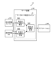
- FIG. 1 is a diagram illustrating an example of a system according to an embodiment.
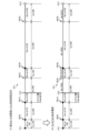
- FIG. 2 is a schematic diagram illustrating an example of the operation of the server device.
- FIG. 3 is a schematic diagram showing an example of the operation of the in-vehicle device.
- FIG. 4 is a diagram illustrating an example of the configuration of the server device and the in-vehicle device according to the embodiment.
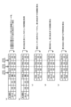
- FIG. 5 is a diagram showing a specific example of a method for estimating the WL type.
- FIG. 6 is a diagram showing a specific example of a method for generating change point information.
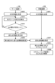
- FIG. 7 is a flowchart showing a procedure for generating change point information.
- FIG. 8 is a flowchart showing a process for regenerating the change point information and distributing the change point information.
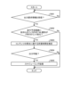
- FIG. 9 is a flowchart showing the procedure of the scheduling process.
- FIG. 10 is a diagram showing a specific example of the scheduling process according to the embodiment.
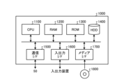
- FIG. 11 is a hardware configuration diagram showing an example of a computer that realizes the functions of the server device.
- Fig. 1 is a diagram showing an example of a system according to an embodiment.
- Fig. 1 shows a system 1 as an example of a system according to an embodiment.
- Information processing according to an embodiment may be realized in the system 1.
- the system 1 may include a cloud system 10 and an in-vehicle device 200.
- the cloud system 10 and the in-vehicle device 200 may be connected to each other via a network N so as to be able to communicate with each other via a wired or wireless connection.
- the cloud system 10 includes a server device 100, which is a central device responsible for information processing according to the embodiment.
- the server device 100 is a device that estimates the type of driving load for each road section included in the planned driving route, which is the route along which the vehicle VE is scheduled to travel.
- the server device 100 also generates information indicating a change point at which the type of driving load changes on the planned driving route, based on the current position of the vehicle VE, the distance of each road section, and the type of driving load estimated for each road section.
- the server device 100 also determines whether the type of driving load currently imposed on the driver of the vehicle VE has changed based on the vehicle's driving conditions, and if the type of driving load has changed, regenerates information indicating the change point. The server device 100 then distributes the regenerated information indicating the change point to the in-vehicle device 200.
- the in-vehicle device 200 may be a dedicated navigation device built into or mounted on the vehicle VE.
- the in-vehicle device 200 may be composed of a navigation device and a recording device.
- the in-vehicle device 200 may be a composite device in which a navigation device and a recording device that are independent of each other are connected so as to be able to communicate with each other.
- the in-vehicle device 200 may be a single device having a navigation function and a recording function.
- the in-vehicle device 200 may also be equipped with various sensors.
- the in-vehicle device 200 may be equipped with various sensors such as a camera, an acceleration sensor, a gyro sensor, a GPS (Global Positioning System) sensor, and an air pressure sensor.
- the in-vehicle device 200 may also have a function of providing dialogue and information to assist driving based on sensor information acquired by the various sensors.
- the in-vehicle device 200 can use not only the sensors provided in the device itself, but also sensor information detected by sensors provided in the vehicle VE itself as a safe driving system.
- the driver can install a specific application software into a portable terminal device (e.g., a smartphone, a tablet terminal, a notebook PC, a PDA, etc.) that he or she uses on a daily basis, and cause the portable terminal device to operate in the same manner as the in-vehicle device 200.
- a portable terminal device e.g., a smartphone, a tablet terminal, a notebook PC, a PDA, etc.
- Fig. 2 is a schematic diagram showing an operation example of the server device 100.
- the cloud system 10 may include the server device 100 having a workload estimation engine E, a situation grasping engine 231, a guidance information DB, and an application MA.
- the workload (WL) referred to here indicates the driving load and may include both the driver's sense of burden (which can also be considered the degree of difficulty) and the driving load set for a road section.
- Types of driving load include, for example, "BUSY,” “IDEAL,” and “FREE,” and indicate that the load on the driver on a road section designated as “BUSY” is above a standard (i.e., driving difficulty is high), the load on the driver on a road section designated as “FREE” is below a standard (i.e., driving difficulty is low or not high), and the load on the driver on a road section designated as "IDEAL” is medium (i.e., driving difficulty is normal or not high).
- the degree of difficulty for the driver may be expressed numerically as the driver's sense of burden, and can be defined as follows:
- a level of difficulty of "1” corresponds to a driving load type of "BUSY_MAX” and is a road section where all general drivers have to be careful when driving, and it is defined that the in-vehicle device 200 should only issue a warning notification on such road sections.
- the level of difficulty "0.80” corresponds to a driving load type of "BUSY+”, and is a road section where more than 60% of general drivers have to be careful when driving. It is defined that in such road sections, the in-vehicle device 200 should only issue warning notifications and caution notifications.
- the level of difficulty "0.60” corresponds to a "BUSY” type of driving load, and is a road section where more than 20% of general drivers have to be careful when driving. It is defined that in such road sections, the in-vehicle device 200 should only issue warning notifications, caution notifications, and important notifications.
- the level of difficulty "0.50” corresponds to the driving load type "IDEAL", and it is defined that in the relevant road section, the in-vehicle device 200 may also speak content other than guidance-related information (warning notifications, caution notifications, important notifications).
- the level of difficulty "0.25" corresponds to the driving load type "FREE,” and is defined as a road section that more than 50% of general drivers would find monotonous and boring, and in which a variety of content should be spoken.
- the types of driving load are not necessarily limited to the above examples ("BUSY_MAX”, “BUSY+”, “BUSY”, “IDEAL”, and “FREE”).
- the types of driving load are expressed as “WL types” and will be explained using “BUSY” and "FREE”.
- the criteria and reference values shown above are merely examples and may be any values.
- a road section means a section between characteristic points of a road, and is called a link. Characteristic points of a road are intersections, corners, dead ends, etc., and are called nodes.
- a link means a road section that is set based on a specific rule.
- a link means a unit that divides a recorded section of a movement history based on a specific rule.
- a road section is represented as a link
- a connection point between road sections is represented as a node.
- the server device 100 has a map information storage unit 121 (FIG. 4), which includes road data that represents a road network as a combination of nodes and links, facility data, and object information around the road.
- the object information includes information on obstacles that exist temporarily, as well as features such as signs such as road signs, road markings such as stop lines, road dividing lines such as center lines, and structures along the road. Obstacles refer to factors that impede the passage of pedestrians and bicycles, such as puddles, sunken parts of the road, fallen objects, and drains (including parts blocked by nets).
- the object information may include highly accurate point cloud information of objects to be used for vehicle position estimation, etc.
- links may be identified by link IDs.
- the situation assessment engine 231 is a cloud service that collects situation information, including analysis results obtained by analyzing sensor information obtained by sensors possessed by the in-vehicle device 200, or the operating status of various applications installed in the in-vehicle device 200, and distributes the accumulated information as situation information.
- the situation assessment engine 231 is included in the cloud system 10, but the in-vehicle device 200 may have the situation assessment engine 231.
- the guidance information DB stores guidance information used to guide the driver along a route that has been set according to the driver's destination, or guidance information used to guide the driver along a route that has been reset (rerouted) when the vehicle VE deviates from the set route.
- the application MA has the function of distributing the results processed by the workload estimation engine E to the information matching engine 232 of the in-vehicle device 200.
- the workload estimation engine E performs information processing according to the embodiment.
- the workload estimation engine E acquires situation information from the situation grasping engine 231, and estimates the type of driving load (WL type) of the vehicle VE at the current time based on the acquired situation information (step S21). For example, the workload estimation engine E may estimate the degree of difficulty (driving load) of the driver (assumed to be driver D) on the road section on which the vehicle VE is currently traveling, i.e., the current link, as the WL type of the vehicle VE at the current time.
- the workload estimation engine E may estimate the degree of difficulty (driving load) of the driver (assumed to be driver D) on the road section on which the vehicle VE is currently traveling, i.e., the current link, as the WL type of the vehicle VE at the current time.
- the workload estimation engine E also estimates the type of future driving load (WL type) of the vehicle VE (step S22). Specifically, the workload estimation engine E estimates (predicts) the WL type for each link included in the planned driving route based on the planned driving route, which is the route along which the vehicle VE is scheduled to travel.
- the workload estimation engine E may compare the planned driving route with map data (map information storage unit 121) in which a WL type is associated with each link, and predict the WL type for each link included in the planned driving route.
- the workload estimation engine E can set a route to the destination as a planned travel route based on a route plan that satisfies the destination. Therefore, in such a case, the workload estimation engine E may refer to the guidance information DB and predict the WL type based on unique information that cannot be obtained from map data that only has a corresponding WL type. As an example, the workload estimation engine E may refer to the guidance information DB and detect the attribute of a first link, which is the link on which the vehicle VE is currently traveling, and the attribute of a second link that is located in the traveling direction of the vehicle VE and is connected to the first link.
- the workload estimation engine E may predict the WL type based on a comparison between the attribute of the first link, "wide road,” and the attribute of the second link, "narrow road.”
- the workload estimation engine E may not need to perform the process of predicting the WL type for each link included in the planned driving route.
- the workload estimation engine E may predict the driving route based on the driving history of the vehicle VE, and set the predicted driving route as the planned driving route.
- the workload estimation engine E also calculates the expected time at which the vehicle VE will arrive at a node included in the planned travel route based on the estimation result (prediction result).
- the expected time is an example of information indicating a change point at which the WL type changes (change point information), and will be described in detail later.
- the workload estimation engine E monitors changes in the current WL type (the degree of difficulty of the driver D) of the vehicle VE based on the traveling conditions of the vehicle VE (condition information acquired from the information matching engine 232).
- the workload estimation engine E can determine that the WL type of the vehicle VE at the current time has changed, for example, by comparing it with the WL type estimated at the previous timing, the workload estimation engine E recalculates the predicted time at which the vehicle VE will arrive at a node included in the planned driving route. In other words, if the workload estimation engine E can determine that the WL type of the vehicle VE at the current time has changed, it recalculates the change point information. Then, the workload estimation engine E delivers the recalculated change point information to the application MA (step S23).
- the application MA delivers the change point information acquired from the workload estimation engine E to the in-vehicle device 200. Specifically, the application MA delivers the change point information acquired from the workload estimation engine E to the information consistency engine 232.
- Fig. 3 is a schematic diagram showing an example of the operation of the in-vehicle device 200.
- the in-vehicle device 200 has an information matching engine 232.
- the information matching engine 232 receives WL information (step S31-1).
- the WL information here is change point information distributed by the server device 100, i.e., information on the predicted time when the vehicle VE will arrive at a node included in the planned driving route.
- the information matching engine 232 searches for links (speech-permitted links) that can be determined to allow content to be output by voice from among the links included in the planned driving route (step S31-2). For example, the information matching engine 232 may search for links that are estimated to be of WL type "FREE" from among the links included in the planned driving route as links that can be determined to allow content to be output by voice.
- the information matching engine 232 also determines whether output request information has been received in a phase separate from steps S31-1 and S31-2.
- the output request information referred to here is output request information sent by various applications installed in the in-vehicle device 200.
- an application that provides content related to tourist information may send output request information to the information matching engine 232 that includes output conditions (time conditions that permit output, or geographical conditions that permit output) and the content to be output.
- the information matching engine 232 When the information matching engine 232 receives output request information (step S32-1), it estimates the time required to play the content included in the output request information (step S32-2). For example, the information matching engine 232 may estimate the time required based on the playback time length of the content included in the output request information.
- the information matching engine 232 determines whether or not the content included in the output request information can be output based on the speech-permitted link searched for in step S31-2 and the required time estimated in step S31-2 (step S33). For example, if the time length of the speech-permitted link is sufficiently longer than the required time, the information matching engine 232 may determine that the content included in the output request information can be output.
- the control process to resolve the output request information is a basic process performed by the information matching engine 232, and indicates scheduling that determines the output timing of the content so as to satisfy the output conditions included in the output request information.
- the timing for outputting the content is determined as a result of scheduling by the information matching engine 232, the content is output as audio from the speaker SP ( Figure 4) of the in-vehicle device 200.
- Fig. 4 is a diagram showing a configuration example of the server device 100 and the in-vehicle device 200 according to the embodiment.
- the communication unit 110 is realized by, for example, a network interface card (NIC) etc.
- the communication unit 110 is connected to a network N by wire or wirelessly, and transmits and receives information to and from the in-vehicle device 200, for example.
- NIC network interface card
- the storage unit 120 is realized by, for example, a semiconductor memory element such as a random access memory (RAM) or a flash memory, or a storage device such as a hard disk or an optical disk.
- the storage unit 120 may store, for example, data and programs related to the information processing according to the embodiment.
- the storage unit 120 may include a map information storage unit 121 and a control result storage unit 122.
- the map information storage unit 121 stores map data used for estimating the WL type.
- the map data includes road data in which a road network is represented by a combination of nodes and links.
- the links are managed by link IDs, and may be associated with the WL type and the link length.
- Control result storage unit 122 The control result storage unit 122 may store information obtained by the workload estimation engine E (for example, the current WL type, the future WL type, change point information, etc.).
- the control unit 130 is realized by a central processing unit (CPU), a micro processing unit (MPU), or the like executing various programs (e.g., the information processing program according to the embodiment) stored in a storage device inside the server device 100 using a RAM as a working area.
- the control unit 130 is also realized by an integrated circuit such as an application specific integrated circuit (ASIC) or a field programmable gate array (FPGA).
- ASIC application specific integrated circuit
- FPGA field programmable gate array
- the control unit 130 is equipped with a workload estimation engine E, which includes an acquisition unit 131, an estimation unit 132, a generation unit 133, a detection unit 134, a determination unit 135, and a delivery unit 136, and realizes or executes the functions and actions of the information processing described below.
- a workload estimation engine E which includes an acquisition unit 131, an estimation unit 132, a generation unit 133, a detection unit 134, a determination unit 135, and a delivery unit 136, and realizes or executes the functions and actions of the information processing described below.
- the internal configuration of the workload estimation engine E is not limited to the configuration shown in FIG. 4, and may be other configurations as long as they perform the information processing described below.
- the connection relationships between the processing units of the workload estimation engine E are not limited to the connection relationships shown in FIG. 4, and may be other connection relationships.
- the acquisition unit 131 acquires information indicating a driving route of the vehicle VE.
- the acquisition unit 131 may acquire information on a planned driving route, which is a route along which the vehicle VE is scheduled to travel, as the information indicating the driving route of the vehicle VE.
- the acquisition unit 131 sets a route to the destination as a planned driving route based on a route plan that satisfies the destination. As a result, the acquisition unit 131 acquires information indicating the set planned driving route.
- the acquisition unit 131 may predict a driving route based on the driving history of the vehicle VE, and set the predicted driving route as the planned driving route. In this case, the acquisition unit 131 acquires information indicating the predicted planned driving route.
- the estimation unit 132 estimates the WL type. For example, the estimation unit 132 estimates the degree of difficulty (driving difficulty) of the driver D in the road section on which the vehicle VE is currently traveling, i.e., the current link, as the WL type of the vehicle VE at the current time. For example, the estimation unit 132 may acquire situation information from the situation grasping engine 231, and estimate the degree of difficulty of the driver D based on the acquired situation information. Furthermore, the estimation unit 132 may compare the current link with map data in which a WL type is associated with each link, and estimate the degree of difficulty of the driver D based on the WL type associated with the current link.
- the estimation unit 132 also estimates the WL type for each link included in the planned driving route, which is the route along which the vehicle VE is scheduled to travel, as the future WL type for the vehicle VE. For example, the estimation unit 132 may compare the planned driving route with map data in which a WL type is associated with each link, and predict the WL type for each link included in the planned driving route.
- the estimation unit 132 may estimate the WL type without relying on map data in which a WL type is associated with each link. For example, the estimation unit 132 may statistically estimate the WL type based on the driving history of each link. As an example, the estimation unit 132 may estimate the WL type as "BUSY" for a link that shows a tendency for sudden braking as a result of analyzing the driving history. The estimation unit 132 may also estimate the WL type based on the driving difficulty calculated from the attributes of the link. For example, the estimation unit 132 may determine that a link with a sharp curve or a steep gradient has a high driving difficulty and estimate the WL type as "BUSY.”
- the estimation unit 132 may also estimate the WL type using the guidance information DB.
- the estimation unit 132 may obtain route guidance corresponding to the planned driving route from the guidance information DB, and the route guidance may include the content "The road width narrows from point XX ahead.”
- the estimation unit 132 may obtain the attribute "wide road” of the first link, which is the link on which the vehicle VE is currently traveling, and the attribute "narrow road” of the second link, which is located in the traveling direction of the vehicle VE and connected to the first link, and may predict the WL type based on a comparison of these attributes.
- the estimation unit 132 may estimate the WL type "FREE” for the first link, which is the link on which the vehicle VE is currently traveling, and estimate the WL type "BUSY” for the second link, which is located in the traveling direction of the vehicle VE and connected to the first link.
- the generation unit 133 generates information indicating change points at which the WL type changes on the planned driving route based on the current position of the vehicle VE, the distance of each link included in the planned driving route, and the WL type of each link.
- the generating unit 133 may generate distance information indicating the distance from the current position of the vehicle VE to the connection point, i.e., the node, where the adjacent links are connected, as information indicating the change point.
- the generation unit 133 may generate, as information indicating a change point, time information indicating the predicted time at which the vehicle VE will reach a node at which the adjacent links are connected from the current position of the vehicle VE.
- the information indicating the change point may also include type information indicating the WL type of the link on which the vehicle VE is currently traveling.
- the detection unit 134 detects a change in the driving scene based on the driving conditions of the vehicle VE. For example, the detection unit 134 detects a change in the driving behavior of the vehicle VE as a change in the driving scene. As an example, the detection unit 134 may detect a significant decrease in speed, a significant increase in speed, a temporary stop, a stop, slow driving, a curve, a sudden start, a sudden brake, an abrupt steering wheel, an impact, and the like as a change in the driving behavior of the vehicle VE.
- the detection unit 134 may also detect, as a change in the driving scene, whether the vehicle VE has entered a point corresponding to a change point where the WL type changes. Specifically, when different WL types are estimated between adjacent links, the detection unit 134 detects whether the vehicle VE has entered a node that is a connection point where the adjacent links are connected.
- the detection unit 134 may also detect, as a change in the driving scene, a change in attributes based on a comparison between the attributes of a first link, among the links included in the planned driving route, along which the vehicle VE is currently traveling, and the attributes of a second link that is located in the traveling direction of the vehicle VE and is connected to the first link. For example, the detection unit 134 may detect entry from a narrow road to a wide road, entry from a wide road to a narrow road, and entry from a road outside the living area to a road within the living area.
- the detection unit 134 may also detect, as a change in the driving scene, whether the vehicle VE has entered an area corresponding to a specific characteristic point that exists in a first link on which the vehicle VE is currently traveling, among the links included in the planned driving route.
- the characteristic point referred to here is, for example, an intersection, a junction, a fork, a toll booth, a railroad crossing, etc.
- the detection unit 134 may also detect, for example, whether the road on which the vehicle VE is currently traveling is an expressway, or whether the road on which the vehicle VE is currently traveling is a road with the same tendency (for example, a straight road) with no change in attributes.
- the determination unit 135 determines whether or not the WL type of the vehicle VE at the current time has changed based on the driving conditions of the vehicle VE. For example, the determination unit 135 may determine whether or not the degree of difficulty for the driver D on the link on which the vehicle VE is currently traveling has changed, as the WL type of the vehicle VE at the current time. For example, the determination unit 135 may determine whether or not the degree of difficulty for the driver D on the link on which the vehicle VE is currently traveling has changed, based on whether or not a change in the driving scene has been detected by the detection unit 134.
- the determination unit 135 may determine that the degree of difficulty of the driver D has changed.
- the determination unit 135 may determine that the degree of difficulty of the driver D has changed if it detects that the vehicle VE has entered a point (node) corresponding to a change point where the WL type changes.
- the determination unit 135 may determine that the degree of difficulty of the driver D has changed if an attribute change is detected between the attribute of a first link along which the vehicle VE is currently traveling and the attribute of a second link that is located in the traveling direction of the vehicle VE and is connected to the first link.
- the determination unit 135 when the determination unit 135 detects that the vehicle VE has entered an area corresponding to a specified characteristic point, it may determine that the degree of difficulty of the driver D has changed.
- the generation unit 133 determines that the current WL type of the vehicle VE has changed (the degree of difficulty of the driver D has changed), it regenerates the change point information (e.g., the expected time that the vehicle VE will arrive at a node included in the planned driving route) that was previously generated based on the estimation result by the estimation unit 132.
- the change point information e.g., the expected time that the vehicle VE will arrive at a node included in the planned driving route
- Distribution unit 1336 When the WL type of the vehicle VE at the current time point changes, the distribution unit 136 distributes to the in-vehicle device 200 information indicating a change point at which the WL type changes on the planned driving route.
- the generation unit 133 recalculates the change point information. As a result, it is possible to cause the in-vehicle device 200 to execute scheduling that utilizes highly accurate change point information with reduced error, thereby making it possible to realize scheduling for outputting content at appropriate timing.
- the in-vehicle device 200 In order to allow the in-vehicle device 200 to execute scheduling using highly accurate change point information with reduced error, it is preferable to generate the latest change point information as appropriate, regardless of changes in the driving scene, and deliver the generated change point information to the in-vehicle device 200.
- the number of times the server device 100 delivers the change point information increases, resulting in a problem that it is not possible to meet the needs of outputting content at an appropriate timing while suppressing communication traffic.
- the server device 100 actually performs recalculation and delivers the change point information obtained by the recalculation to the in-vehicle device 200 only when it is determined that the degree of difficulty of the driver D has changed in response to a change in the driving scene, that is, when there is an increased need to recalculate the change point information.
- the server device 100 can meet the above needs.
- the in-vehicle device 200 has a microphone MC, a speaker SP, a sensor SC, an application AP, a communication unit 210, a storage unit 220, and a control unit 230.
- the microphone MC is a sound collecting device that collects sounds generated within the vehicle VE. For example, the microphone MC collects speech generated by the driver D.
- the speaker SP corresponds to an output device that outputs various information by sound.
- the speaker SP outputs content information in accordance with output control by the control unit 230.
- the sensor SC detects various information related to the vehicle VE and transmits the detected sensor information to the situation assessment engine 231.
- the application AP is an application that provides content.
- the application AP transmits output request information including output conditions (time conditions for permitting output or geographic conditions for permitting output) and content to be output to the information matching engine 232.
- the system 1 may further include an application server that controls the application AP.
- the storage unit 220 is realized by, for example, a semiconductor memory element such as a RAM or a flash memory, or a storage device such as a hard disk or an optical disk.
- the storage unit 220 may store, for example, data and programs related to the information processing according to the embodiment.
- the storage unit 220 may include a user information storage unit 221 and a content storage unit 222.
- the user information storage unit 221 stores various information related to a user (e.g., a driver D) of the vehicle VE.
- the user information storage unit 221 may store a user related to the vehicle VE, and may further store a driving history of the vehicle VE.
- the content storage unit 222 stores the content provided by the application AP.
- the control unit 230 is realized by a CPU, an MPU, or the like executing various programs (e.g., the information processing program according to the embodiment) stored in a storage device inside the in-vehicle device 200 using a RAM as a working area.
- the control unit 230 is also realized by an integrated circuit such as an ASIC or an FPGA.
- control unit 230 has a situation understanding engine 231, an information matching engine 232, and an output control unit 233, and realizes or executes the information processing functions and actions described below.
- the internal configuration of the control unit 230 is not limited to the configuration shown in FIG. 4, and may be other configurations as long as they perform the information processing described below.
- the connection relationships between the processing units in the control unit 230 are not limited to the connection relationships shown in FIG. 4, and may be other connection relationships.
- the situation recognition engine 231 identifies the situation related to the vehicle VE based on the sensor information. For example, the situation recognition engine 231 identifies the situation of the vehicle VE by detecting the voice, the state, the behavior of the vehicle VE, etc. inside the vehicle VE. Then, the situation recognition engine 231 outputs situation information indicating the identified situation to the information matching engine 232.
- the information matching engine 232 searches for links (speech-permitted links) that can be determined to allow output of content by voice from among the links included in the planned driving route.
- the information matching engine 232 when the information matching engine 232 receives output request information, it estimates the time required to play the content included in the output request information.
- the information matching engine 232 also determines whether the content included in the output request information can be output based on the speech allowable link and the required time.
- the information matching engine 232 executes a scheduling process that determines the output timing of the content so as to satisfy the output conditions included in the output request information.
- the output control unit 233 controls the content to be output from the speaker SP at the timing scheduled by the information matching engine 232 .
- WL type estimation method From here, the WL type estimation method will be specifically described with reference to Fig. 5.
- Fig. 5 is a diagram showing a specific example of the WL type estimation method. In Fig. 5, the WL type estimation method will be described using an example in which a travel route RT1 is plotted according to a route plan that satisfies the destination.
- the travel route RT1 is a route connecting a starting point PT1 and a destination point PT3, and the scene in which the WL type estimation process starts when the vehicle VE is located at a position PT2 is shown.
- the position PT2 corresponds to the current location of the vehicle VE.
- the estimation unit 132 compares the travel route RT1 with map data in which a WL type is associated with each link, and links each link that constitutes the travel route RT1 with a link ID (link_id).
- FIG. 5(a) shows an example in which the estimation unit 132 divides the travel route RT1 into five links by linking link ID "100", link ID "101", link ID "102", link ID "103", link ID "104", and link ID "105" to the travel route RT1.
- node ND01 is shown as information on the connection point where the link identified by link ID "100" (link 100) and the link identified by link ID "101" (link 101) are connected.
- node ND12 is shown as information on the connection point where the link identified by link ID "101" (link 101) and the link identified by link ID "102" (link 102) are connected.
- node ND23 is shown as information on the connection point where the link identified by link ID "102" (link 102) and the link identified by link ID "103" (link 103) are connected.
- node ND34 is shown as information on the connection point where the link identified by link ID "103" (link 103) and the link identified by link ID "104" (link 104) are connected.
- node ND45 is shown as information on the connection point where the link identified by link ID "104" (link 104) and the link identified by link ID "105" (link 105) are connected.
- the estimation unit 132 may also refer to the map data and calculate the distance (len) of each link.
- FIG. 5(a) shows an example in which the estimation unit 132 calculates the distance "100" of link 100, the distance "200” of link 101, the distance "300” of link 102, the distance "100” of link 103, the distance “500” of link 104, and the distance "200” of link 105.
- the estimation unit 132 may estimate the WL type for the link including the current location PT2 of the vehicle VE, i.e., link 102 on which the vehicle VE is currently traveling, and links 103, 104, and 105 which are scheduled to be traveled after link 102.
- FIG. 5(b) shows an example in which the estimation unit 132 refers to map data in which a WL type is associated with each link, and estimates the WL type of link 102 as "FREE", the WL type of link 103 as "BUSY”, the WL type of link 104 as "FREE", and the WL type of link 105 as "BUSY".
- the estimation unit 132 may also estimate the degree of difficulty of the driver D on the link 102 on which the vehicle VE is currently traveling as the WL type of the vehicle VE at the current time.
- Fig. 6 is a diagram showing a specific example of a method for generating change point information. Fig. 6 describes the method for generating change point information using the same scene as Fig. 5 as an example.
- the generation unit 133 detects a node that connects links of different WL types as a change point where the WL type changes.
- node ND23 is a node that connects link 102 of WL type "FREE” and link 103 of WL type "BUSY”.
- Node ND34 is a node that connects link 103 of WL type "BUSY” and link 104 of WL type "FREE”.
- Node ND45 is a node that connects link 104 of WL type "FREE” and link 105 of WL type "BUSY”.
- the generation unit 133 detects nodes ND23, ND34, and ND45 as nodes that connect links of different WL types as change points where the WL type changes.
- node ND23 may be referred to as change point CP23, node ND34 as change point CP34, and node ND45 as change point CP45.
- the generation unit 133 acquires the distance (link length information) of each link that includes the change points (CP23, CP34, CP45). Since the links that include the change points (CP23, CP34, CP45) are link 102, link 103, link 105, and link 105, the generation unit 133 acquires the distance "300” for link 102, the distance "100” for link 103, the distance "500” for link 104, and the distance "200” for link 105.
- the generation unit 133 calculates the distance (dist) from node ND12, which is included in link 102 on which the vehicle VE is currently traveling, to the change points (CP23, CP34, CP45). Since the distance of link 102 is "300", the generation unit 133 calculates the distance from node ND12 to change point CP23 as "300".
- the generation unit 133 also adds the distance "300” of link 102 and the distance “100” of link 103 to calculate the distance "400” from node ND12 to change point CP34.
- the generation unit 133 adds the distance "300” of link 102, the distance “100” of link 103, and the distance “500” of link 104 to calculate the distance "900" from node ND12 to change point CP45.
- the generation unit 133 calculates the distance (dist) from the current location PT2 of the vehicle VE to the change points (CP23, CP34, CP45) as shown in FIG. 6(d).
- the current location PT2 of the vehicle VE corresponds to a position 120 m away from the node ND12. Therefore, the generation unit 133 subtracts "120" from the distance "300" from the node ND12 to the change point CP23 to calculate the distance "180" from the current location PT2 to the change point CP23.
- the generation unit 133 also subtracts "120" from the distance "400” from node ND12 to change point CP34 to calculate the distance "280" from current location PT2 to change point CP34.
- the generation unit 133 subtracts "120” from the distance "900” from node ND12 to change point CP45 to calculate the distance "780” from current location PT2 to change point CP45.
- the generation unit 133 determines the distance from the current location PT2 to the change point CP23 as "180", the distance from the current location PT2 to the change point CP34 as "280", and the distance from the current location PT2 to the change point CP45 as "780" as information indicating the change point.
- the generation unit 133 generates the distance "180" from the current location PT2 to the change point CP23 as the change point information indicating the change point CP23.
- the generation unit 133 also generates the distance "280" from the current location PT2 to the change point CP34 as the change point information indicating the change point CP34.
- the generation unit 133 also generates the distance "780" from the current location PT2 to the change point CP45 as the change point information indicating the change point CP45.
- the generation unit 133 calculates the predicted times at which the vehicle VE will arrive at the change points (CP23, CP34, CP45) based on the distance (dist) from the current position PT2 of the vehicle VE to the change points (CP23, CP34, CP45) and the speed of the vehicle VE.
- FIG. 6(e) shows an example in which the generation unit 133 calculates the predicted time "TM23” at which the vehicle VE will arrive at the change point CP23, the predicted time "TM34” at which the vehicle VE will arrive at the change point CP34, and the predicted time "TM45” at which the vehicle VE will arrive at the change point CP45.
- the generation unit 133 defines the predicted time “TM23”, the predicted time “TM34”, and the predicted time “TM45” as information indicating a change point. Specifically, the generation unit 133 generates the predicted time “TM23” as change point information indicating the change point CP23. The generation unit 133 also generates the predicted time “TM34” as change point information indicating the change point CP34. The generation unit 133 also generates the predicted time "TM45” as change point information indicating the change point CP45.
- Procedure for generating change point information 7 is a flowchart showing a procedure for generating the change point information, which is described with reference to FIGS.
- the acquisition unit 131 acquires information indicating the driving route of the vehicle VE (step S701). For example, the acquisition unit 131 acquires information on a planned driving route, which is a route along which the vehicle VE is scheduled to travel, as information indicating the driving route of the vehicle VE.
- the estimation unit 132 determines whether it is time to estimate the WL type (step S702). For example, the estimation unit 132 may determine that it is time to estimate the WL type when a certain period of time has passed since the vehicle VE started traveling, or when the vehicle VE has traveled a certain distance since it started traveling.
- step S702 If it is not time to estimate the WL type (step S702; No), the estimation unit 132 waits until it can determine that it is time to estimate the WL type.
- the estimation unit 132 estimates the degree of difficulty (driving difficulty) of the driver D on the link on which the vehicle VE is currently traveling based on the situation information acquired from the situation understanding engine 231 (step S703).
- the estimation unit 132 also predicts the WL type for each link included in the planned driving route (step S704). For example, the estimation unit 132 may compare the planned driving route with map data and estimate the WL type for each link including the current location of the vehicle VE, i.e., the link on which the vehicle VE is currently traveling, and the link that is planned to be traveled after that link. The estimation unit 132 may determine the WL type estimated for the link on which the vehicle VE is currently traveling as the degree of difficulty for the driver D.
- step S705 determines whether or not a node that connects links of different WL types exists based on the estimation result obtained in step S704 (step S705). If a node that connects links of different WL types does not exist (step S705; No), the process proceeds to step S702.
- step S705 if there is a node connecting links with different WL types (step S705; Yes), the generation unit 133 detects this as a change point where the WL type changes (step S706).
- a change point where the WL type changes is an example of a change point where the WL type changes.
- the generation unit 133 generates change point information based on the information about the change point (step S707). For example, the generation unit 133 calculates the distance from the current location to the change point based on the current location of the vehicle VE and the distance of the link connected by the change point where the WL type changes, and generates the calculated distance as change point information. The generation unit 133 also calculates a predicted time at which the vehicle VE will arrive at the change point based on the current location of the vehicle VE and the distance of the link connected by the change point where the WL type changes, and generates the calculated predicted time as change point information.
- the generation unit 133 also registers the generated change point information in the control result storage unit 122 (step S708).
- FIG. 8 is a flowchart showing a process for regenerating the change point information and distributing the change point information.
- the situation grasping engine 231 of the in-vehicle device 200 may periodically transmit situation information obtained from sensor information, etc., to the server device 100 (step S801).
- the situation information includes various information related to the driving situation of the vehicle VE.
- the detection unit 134 of the server device 100 receives the situation information sent by the situation assessment engine 231 (step S802).
- the detection unit 134 identifies the driving scene of the vehicle VE based on the situation information, and detects a change in the driving scene based on the previous and following driving scenes (step S803).
- the detection unit 134 detects a change in the driving behavior of the vehicle VE as a change in the driving scene.
- the detection unit 134 may detect a significant decrease in speed, a significant increase in speed, a temporary stop, a stop, slow driving, a curve, a sudden start, a sudden brake, an abrupt turn, an impact, etc. as a change in the driving behavior of the vehicle VE.
- the detection unit 134 may also detect, as a change in the driving scene, whether the vehicle VE has entered a change point where the WL type changes. For example, using the example of FIG. 6, the detection unit 134 may detect whether the vehicle VE has entered the change point CP23 (node ND23).
- the detection unit 134 may detect, as a change in the driving scene, a change in attribute based on a comparison between the attribute of a first link, among the links included in the planned driving route, along which the vehicle VE is currently traveling, and the attribute of a second link that is located in the traveling direction of the vehicle VE and is connected to the first link. For example, in the example of FIG. 5, it is assumed that the attribute of the link 102 along which the vehicle VE is currently traveling is "wide road", the attribute of the link 103 connected to the link 102 is "narrow road”, and it is predetermined in the guidance information DB that a change in attribute from "wide road” to "narrow road” is notified at a guidance point on the link 102. In this case, the detection unit 134 may detect the attribute change from "wide road” to "narrow road” based on the guidance information registered in the guidance information DB, and may detect a change in the driving scene when the vehicle VE reaches the guidance point.
- the detection unit 134 may also detect, as a change in the driving scene, whether the vehicle VE has entered an area corresponding to a predetermined characteristic point present on the link on which the vehicle VE is currently traveling, among the links included in the planned driving route.
- the determination unit 135 determines whether the WL type of the vehicle VE at the current time has changed based on the detection result by the detection unit 134 (step S804). For example, the determination unit 135 may determine, as the WL type of the vehicle VE at the current time, whether the degree of difficulty of the driver D on the link on which the vehicle VE is currently traveling has changed.
- step S804 If it is determined that there is no change in the current WL type of the vehicle VE (step S804; No), the process returns to step S803.
- step S804 determines that there is no change in the current WL type of the vehicle VE (step S804; Yes)
- the generation unit 133 recognizes that there is a high probability that the speed of the vehicle VE has changed between when the change point information (estimated time) was calculated in the flow described in FIG. 7 and the present time when the change in the driving scene has been detected (i.e., there is a high probability that the estimated time has changed (an error has occurred)), and that it is necessary to recalculate the estimated time.
- the generation unit 133 predicts the time that the vehicle VE will be stopped.
- the generation unit 133 may predict the time that the vehicle VE will be stopped based on statistical information at the position where the vehicle VE is stopped. For example, if the generation unit 133 predicts that the vehicle VE will be stopped for "30 seconds,” it recalculates the predicted time by adding "30 seconds" to the predicted time calculated in the flow described in FIG. 7.
- the distribution unit 136 distributes the change point information regenerated in step S805 to the in-vehicle device 200 (step S806).
- the distribution unit 136 may transmit, as the regenerated change point information, the recalculated result of the predicted time for the vehicle VE to reach the change point.
- the information matching engine 232 of the in-vehicle device 200 receives the change point information distributed by the distribution unit 136 (step S807). Then, the information matching engine 232 performs scheduling to determine the time to output the content based on the change point information (step S808).
- the output control unit 233 controls the content to be output from the speaker SP at the timing scheduled by the information matching engine 232 (step S809).
- Fig. 9 is a flowchart showing the procedure of the scheduling process.
- the information matching engine 232 determines whether output request information has been received from the application AP (step S901).
- the output request information may include output conditions (time conditions under which output is permitted, or geographical conditions under which output is permitted) and the content to be output. If the information matching engine 232 has not received output request information (step S901; No), it waits until it can receive output request information.
- the information matching engine 232 receives output request information (step S901; Yes), it determines whether or not there is a link whose WL type is estimated to be "FREE" among the links included in the planned driving route (step S902). This process corresponds to a process of searching for a link (speech-permitted link) from among the links included in the planned driving route, for which it is determined that it is OK to output content by voice. If, as a result of the search, there is no link whose WL type is estimated to be "FREE" (step S902; No), the information matching engine 232 may end the scheduling process.
- the information matching engine 232 estimates the time required to play the content based on the playback time length of the content included in the output request information (step S903).
- the required time refers to the time required from the start to the end of playback of the content.
- the information matching engine 232 also determines whether or not the content included in the output request information can be output for the link based on the link estimated to be of WL type "FREE" and the required time (step S904). For example, if the time length of the link estimated to be of WL type "FREE" is sufficiently longer than the required time, the information matching engine 232 may determine that the content included in the output request information can be output.
- step S904 If output is not possible (step S904; No), the information matching engine 232 may end the scheduling process. On the other hand, if output is possible (step S904; Yes), the information matching engine 232 determines the scheduled time for outputting the content based on the change point information (step S905). For example, the information matching engine 232 determines the scheduled time for outputting the content so as to satisfy the output conditions included in the output request information.
- FIG. 10 is a diagram showing a specific example of the scheduling process according to the embodiment.
- the process performed while the vehicle VE was traveling at position PT2 calculates the predicted time "14:15" when the vehicle VE will reach change point CP23 as change point information indicating change point CP23, and also calculates the predicted time "14:16" when the vehicle VE will reach change point CP34 as change point information indicating change point CP34.
- the generation unit 133 recalculates the change point information, thereby updating the predicted time that the vehicle VE will reach change point CP23 to "14:17", and the predicted time that the vehicle VE will reach change point CP34 to "14:18".
- the distribution unit 136 distributes change point information indicating the predicted time "14:17” and change point information indicating the predicted time "14:18" to the in-vehicle device 200.
- the information matching engine 232 receives output request information for content C1 and output request information for content C2, it proceeds with the process according to the flow described in FIG. 9. For example, if the information matching engine 232 determines that content C1 can be output via link 102 after taking into consideration the output conditions for content C1, it may determine, as the scheduled time for outputting content C1, the time at which playback of content C1 will be completed by the predicted time "14:17", as shown in FIG. 10.
- the information matching engine 232 determines that content C2 can be output on link 104 after taking into consideration the output conditions of content C2, it may determine, as the planned time to output content C2, a time after the predicted time "14:18" at which playback of content C2 will be completed before the vehicle VE has passed link 104, as shown in FIG. 10.
- the information matching engine 232 schedules the content to be output when the vehicle VE travels through a link whose WL type is estimated to be "FREE".
- the information matching engine 232 may schedule the content to be output when the vehicle VE travels through a link whose WL type is estimated to be "BUSY" depending on the importance.
- the information matching engine 232 may schedule the content whose importance is "low” and whose impact is not felt even if the driver D misses it to be output when the vehicle VE travels through a link whose WL type is estimated to be "FREE".
- the information matching engine 232 schedules the content whose importance is "high” and whose useful content should not be missed by the driver D to be output when the vehicle VE travels through a link whose WL type is estimated to be "FREE".
- the information matching engine 232 may schedule content for which the importance level is set to "high” to be output when the vehicle VE travels through the link with the WL type "BUSY.”
- the above-described server device 100 may be realized, for example, by a computer 1000 having a configuration as shown in Fig. 11.
- Fig. 11 is a hardware configuration diagram showing an example of a computer that realizes the functions of the server device 100.
- the computer 1000 has a CPU 1100, a RAM 1200, a ROM 1300, a HDD 1400, a communication interface (I/F) 1500, an input/output interface (I/F) 1600, and a media interface (I/F) 1700.
- the CPU 1100 operates based on the programs stored in the ROM 1300 or the HDD 1400, and controls each component.
- the ROM 1300 stores a boot program executed by the CPU 1100 when the computer 1000 starts up, and programs that depend on the hardware of the computer 1000, etc.
- HDD 1400 stores programs executed by CPU 1100 and data used by such programs.
- Communication interface 1500 receives data from other devices via a specified communication network and sends it to CPU 1100, and transmits data generated by CPU 1100 to other devices via the specified communication network.
- the CPU 1100 controls an output device such as a display and an input device such as a keyboard via the input/output interface 1600.
- the CPU 1100 acquires data from the input device via the input/output interface 1600.
- the CPU 1100 also outputs generated data to the output device via the input/output interface 1600.
- the media interface 1700 reads a program or data stored in the recording medium 1800 and provides it to the CPU 1100 via the RAM 1200.
- the CPU 1100 loads the program from the recording medium 1800 onto the RAM 1200 via the media interface 1700 and executes the loaded program.
- the recording medium 1800 is, for example, an optical recording medium such as a DVD (Digital Versatile Disc) or a PD (Phase change rewritable Disk), a magneto-optical recording medium such as an MO (Magneto-Optical disk), a tape medium, a magnetic recording medium, or a semiconductor memory.
- the CPU 1100 of the computer 1000 executes programs loaded onto the RAM 1200 to realize the functions of the control unit 130.
- the CPU 1100 of the computer 1000 reads and executes these programs from the recording medium 1800, but as another example, the CPU 1100 may obtain these programs from another device via a specified communication network.
- each component of each device shown in the figure is a functional concept, and does not necessarily have to be physically configured as shown in the figure.
- the specific form of distribution and integration of each device is not limited to that shown in the figure, and all or part of them can be functionally or physically distributed and integrated in any unit depending on various loads, usage conditions, etc.
- some or all of the processing described as being performed by the server device 100 may be configured to be performed on the in-vehicle device 200 side.
Landscapes
- Engineering & Computer Science (AREA)
- Radar, Positioning & Navigation (AREA)
- Remote Sensing (AREA)
- Physics & Mathematics (AREA)
- General Physics & Mathematics (AREA)
- Automation & Control Theory (AREA)
- Mathematical Physics (AREA)
- Navigation (AREA)
Priority Applications (3)
| Application Number | Priority Date | Filing Date | Title |
|---|---|---|---|
| EP22968436.0A EP4636726A1 (en) | 2022-12-13 | 2022-12-13 | Information processing device, information processing method, and information processing program |
| PCT/JP2022/045931 WO2024127524A1 (ja) | 2022-12-13 | 2022-12-13 | 情報処理装置、情報処理方法、および、情報処理プログラム |
| JP2024564016A JPWO2024127524A1 (https=) | 2022-12-13 | 2022-12-13 |
Applications Claiming Priority (1)
| Application Number | Priority Date | Filing Date | Title |
|---|---|---|---|
| PCT/JP2022/045931 WO2024127524A1 (ja) | 2022-12-13 | 2022-12-13 | 情報処理装置、情報処理方法、および、情報処理プログラム |
Publications (1)
| Publication Number | Publication Date |
|---|---|
| WO2024127524A1 true WO2024127524A1 (ja) | 2024-06-20 |
Family
ID=91484532
Family Applications (1)
| Application Number | Title | Priority Date | Filing Date |
|---|---|---|---|
| PCT/JP2022/045931 Ceased WO2024127524A1 (ja) | 2022-12-13 | 2022-12-13 | 情報処理装置、情報処理方法、および、情報処理プログラム |
Country Status (3)
| Country | Link |
|---|---|
| EP (1) | EP4636726A1 (https=) |
| JP (1) | JPWO2024127524A1 (https=) |
| WO (1) | WO2024127524A1 (https=) |
Citations (4)
| Publication number | Priority date | Publication date | Assignee | Title |
|---|---|---|---|---|
| WO2018003866A1 (ja) * | 2016-06-29 | 2018-01-04 | 京セラ株式会社 | 走行支援装置、撮像装置、撮像システム、走行支援システム、車両、および走行支援方法 |
| JP2018006338A (ja) | 2016-06-28 | 2018-01-11 | 株式会社 Ngr | 画像生成装置 |
| JP2019100763A (ja) * | 2017-11-29 | 2019-06-24 | クラリオン株式会社 | すれ違い困難区間回避システム、サーバ装置、情報表示装置およびすれ違い困難区間回避方法 |
| WO2022254561A1 (ja) * | 2021-05-31 | 2022-12-08 | パイオニア株式会社 | 情報処理装置、情報処理方法および情報処理プログラム |
Family Cites Families (2)
| Publication number | Priority date | Publication date | Assignee | Title |
|---|---|---|---|---|
| JP2005010664A (ja) * | 2003-06-20 | 2005-01-13 | Matsushita Electric Ind Co Ltd | 車載用コンテンツ再生システム |
| EP1920534A2 (en) * | 2005-01-14 | 2008-05-14 | Philips Intellectual Property & Standards GmbH | A method for selecting audio content to be played in a vehicle |
-
2022
- 2022-12-13 EP EP22968436.0A patent/EP4636726A1/en active Pending
- 2022-12-13 JP JP2024564016A patent/JPWO2024127524A1/ja active Pending
- 2022-12-13 WO PCT/JP2022/045931 patent/WO2024127524A1/ja not_active Ceased
Patent Citations (4)
| Publication number | Priority date | Publication date | Assignee | Title |
|---|---|---|---|---|
| JP2018006338A (ja) | 2016-06-28 | 2018-01-11 | 株式会社 Ngr | 画像生成装置 |
| WO2018003866A1 (ja) * | 2016-06-29 | 2018-01-04 | 京セラ株式会社 | 走行支援装置、撮像装置、撮像システム、走行支援システム、車両、および走行支援方法 |
| JP2019100763A (ja) * | 2017-11-29 | 2019-06-24 | クラリオン株式会社 | すれ違い困難区間回避システム、サーバ装置、情報表示装置およびすれ違い困難区間回避方法 |
| WO2022254561A1 (ja) * | 2021-05-31 | 2022-12-08 | パイオニア株式会社 | 情報処理装置、情報処理方法および情報処理プログラム |
Non-Patent Citations (1)
| Title |
|---|
| See also references of EP4636726A1 |
Also Published As
| Publication number | Publication date |
|---|---|
| EP4636726A1 (en) | 2025-10-22 |
| JPWO2024127524A1 (https=) | 2024-06-20 |
Similar Documents
| Publication | Publication Date | Title |
|---|---|---|
| CN113167590B (zh) | 用于地图匹配的系统和方法 | |
| JP2019510674A (ja) | 不測の歩行者に対する軌道計画を行うシステム及び方法 | |
| CN107042825A (zh) | 车道保持辅助系统的情景停用 | |
| JP2006208385A (ja) | 旅行計画方法、システム及び論理プログラム | |
| JP2004340967A (ja) | オフロードナビゲーションおよび対応するナビゲーションシステムを支援する方法 | |
| JP5499901B2 (ja) | 走行支援方法、走行支援装置及び走行支援プログラム | |
| JP2006209106A (ja) | 地図情報更新装置および地図情報更新方法 | |
| KR102732488B1 (ko) | 군집 주행차량에 대한 교통 정보 운용 시스템 및 방법 | |
| JP2024148100A (ja) | 情報処理装置、情報処理方法、および、情報処理プログラム | |
| JP2025168489A (ja) | 情報処理装置 | |
| JP2025126318A (ja) | 情報処理装置、情報処理方法および情報処理プログラム | |
| JP4677794B2 (ja) | コーナ情報提供装置 | |
| WO2024127524A1 (ja) | 情報処理装置、情報処理方法、および、情報処理プログラム | |
| JP2024084534A (ja) | 情報処理装置、情報処理方法、および、情報処理プログラム | |
| JP7791366B2 (ja) | 情報処理装置、情報処理方法、および、情報処理プログラム | |
| JP6656693B2 (ja) | 情報出力プログラム、情報出力方法及び車載装置 | |
| CN110113716B (zh) | 一种路径状态信息获取方法、装置及存储介质 | |
| WO2024209570A1 (ja) | 情報処理装置、情報処理方法、および、情報処理プログラム | |
| JP7672285B2 (ja) | 情報処理装置、情報処理方法および情報処理プログラム | |
| JP7662775B2 (ja) | 情報処理装置、情報処理方法および情報処理プログラム | |
| JP7672487B2 (ja) | 情報処理装置、情報処理方法および情報処理プログラム | |
| WO2024209567A1 (ja) | 情報処理装置、情報処理方法、および、情報処理プログラム | |
| WO2024209566A1 (ja) | 情報処理装置、情報処理方法、および、情報処理プログラム | |
| WO2021171433A1 (ja) | 情報処理装置、情報処理方法およびプログラム | |
| JP7821621B2 (ja) | 情報処理装置、情報処理方法および情報処理プログラム |
Legal Events
| Date | Code | Title | Description |
|---|---|---|---|
| 121 | Ep: the epo has been informed by wipo that ep was designated in this application |
Ref document number: 22968436 Country of ref document: EP Kind code of ref document: A1 |
|
| WWE | Wipo information: entry into national phase |
Ref document number: 2024564016 Country of ref document: JP |
|
| WWE | Wipo information: entry into national phase |
Ref document number: 2022968436 Country of ref document: EP |
|
| NENP | Non-entry into the national phase |
Ref country code: DE |
|
| ENP | Entry into the national phase |
Ref document number: 2022968436 Country of ref document: EP Effective date: 20250714 |
|
| WWP | Wipo information: published in national office |
Ref document number: 2022968436 Country of ref document: EP |