WO2024127510A1 - 伝送システム、伝送方法及び伝送プログラム - Google Patents
伝送システム、伝送方法及び伝送プログラム Download PDFInfo
- Publication number
- WO2024127510A1 WO2024127510A1 PCT/JP2022/045884 JP2022045884W WO2024127510A1 WO 2024127510 A1 WO2024127510 A1 WO 2024127510A1 JP 2022045884 W JP2022045884 W JP 2022045884W WO 2024127510 A1 WO2024127510 A1 WO 2024127510A1
- Authority
- WO
- WIPO (PCT)
- Prior art keywords
- video
- vibration
- sound
- environmental
- unit
- Prior art date
- Legal status (The legal status is an assumption and is not a legal conclusion. Google has not performed a legal analysis and makes no representation as to the accuracy of the status listed.)
- Ceased
Links
Images






Classifications
-
- H—ELECTRICITY
- H04—ELECTRIC COMMUNICATION TECHNIQUE
- H04N—PICTORIAL COMMUNICATION, e.g. TELEVISION
- H04N21/00—Selective content distribution, e.g. interactive television or video on demand [VOD]
- H04N21/60—Network structure or processes for video distribution between server and client or between remote clients; Control signalling between clients, server and network components; Transmission of management data between server and client, e.g. sending from server to client commands for recording incoming content stream; Communication details between server and client
-
- H—ELECTRICITY
- H04—ELECTRIC COMMUNICATION TECHNIQUE
- H04N—PICTORIAL COMMUNICATION, e.g. TELEVISION
- H04N21/00—Selective content distribution, e.g. interactive television or video on demand [VOD]
- H04N21/60—Network structure or processes for video distribution between server and client or between remote clients; Control signalling between clients, server and network components; Transmission of management data between server and client, e.g. sending from server to client commands for recording incoming content stream; Communication details between server and client
- H04N21/63—Control signaling related to video distribution between client, server and network components; Network processes for video distribution between server and clients or between remote clients, e.g. transmitting basic layer and enhancement layers over different transmission paths, setting up a peer-to-peer communication via Internet between remote STB's; Communication protocols; Addressing
Definitions
- e-sports As communication technology advances, it has become possible for people in remote locations to participate in various social activities together via networks.
- One example of such social activities is e-sports.
- e-sports have begun to appear that combine physical sports with e-sports, allowing players to enjoy playing with people in remote locations while actually moving their bodies. This combination of physical sports and e-sports allows players to gain new experiences that they would not be able to get from physical sports or e-sports alone.
- VR Virtual Reality
- the embodiments provide a transmission system, a transmission method, and a transmission program that transmit events that occur in remote locations without delay and reproduce them synchronously and without contradictions.
- the transmission system of one embodiment has a transmitting device and a receiving device.
- the transmitting device includes a camera that records at least an image of the field of view of a real runner riding on a first object, an environmental sound collecting microphone that collects environmental sounds around the real runner, a vibration sound collecting microphone that collects vibration sounds caused by vibrations of the first object, a video compression unit that compresses the image, an audio compression unit that compresses the environmental sounds and vibration sounds, a synchronization processing unit that synchronizes the image, the environmental sounds, and the vibration sounds, and a transmitting unit that transmits the synchronized image, the environmental sounds, and the vibration sounds to a receiving device.
- the receiving device includes a receiving unit that receives the image, the environmental sounds, and the vibration sounds transmitted by the transmitting unit, a video decoding unit that decodes the received image, an audio decoding unit that decodes the received environmental sounds and vibration sounds, a video output device that outputs the decoded image to a virtual runner riding on a second object corresponding to the first object, an environmental sound output device that outputs the decoded environmental sounds to the virtual runner, and a vibration presentation device that presents the decoded vibration sounds to the virtual runner.
- the embodiments can provide a transmission system, a transmission method, and a transmission program that can transmit events that occur in remote locations without delay and reproduce them synchronously and without contradictions.
- FIG. 1 is a diagram illustrating an example of a configuration of a transmission system according to an embodiment.
- FIG. 2 is a block diagram showing an electrical configuration of the transmission system according to the embodiment.
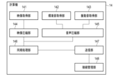
- FIG. 3 is a functional block diagram of the computer 14.
- FIG. 4 is a functional block diagram of the computer 26.
- FIG. 5 is a flowchart showing the operation of a transmitting device in the transmission system.
- FIG. 6 is a flowchart showing the operation of a receiving device in a transmission system.
- FIG. 7 is a diagram illustrating an example of a configuration of a transmission system according to the first modification.
- FIG. 8 is a block diagram showing an electrical configuration of a transmission system according to the first modified example.
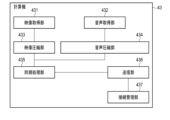
- FIG. 9 is a functional block diagram of the computer 43.
- FIG. 10 is a functional block diagram of the computer 26.
- FIG. 11 is a block diagram showing an example of a hardware configuration of a computer.
- FIG. 1 is a diagram showing the configuration of an example of a transmission system in an embodiment.
- the transmission system 1 includes a transmitting device 10 and a receiving device 20.
- the transmitting device 10 and the receiving device 20 communicate with each other via a network 30.
- the transmission system 1 in FIG. 1 shows an example of its application to cycling.
- the transmitting device 10 is mounted on the bicycle body, which is the object ridden by the actual rider, who is the user of the transmitting device.
- the actual rider rides the bicycle body and actually rides the bicycle.
- the transmitting device 10 transmits to the receiving device 20 information on the field of view while the bicycle is in motion, information on the sounds of the surrounding environment, and information on the vibrations of the bicycle body.
- the transmitting device 10 has a camera 11, an environmental sound collecting microphone (microphone) 12, and a vibration sound collecting microphone (microphone) 13.
- the camera 11 is provided, for example, at the front of the bicycle body, for example at the handlebar position, and records an image of the field of view in front of the bicycle body.
- the environmental sound collecting microphone 12 is provided, for example, at the front of the bicycle body, for example at the handlebar position, and collects environmental sounds around the bicycle body.
- the vibration sound collecting microphone 13 is provided near the source of vibration in the bicycle body, for example near the handlebars, saddle, etc. of the bicycle body, and collects vibration sounds caused by vibrations of the bicycle body.
- the information collected by the camera 11, the environmental sound collecting microphone 12, and the vibration sound collecting microphone 13 is transmitted to a computer provided on the bicycle body.
- the number and positions of the camera 11, the environmental sound collecting microphone 12, and the vibration sound collecting microphone 13 are not limited to those shown in FIG. 1.
- the camera 11 and the environmental sound collection microphone 12 may not be mounted on the bicycle body, but may be mounted, for example, on the head of the actual rider.
- the receiving device 20 is installed in a remote location relative to the transmitting device 10.
- the receiving device 20 receives information transmitted from the transmitting device 10 and recreates the riding of a virtual bicycle based on the received information.
- a virtual rider who is a user of the receiving device, can ride the indoor trainer 23, which is the riding object, and experience the riding of a virtual bicycle recreated by the receiving device 20.
- the receiving device 20 has a video output device 21, an environmental sound output device 22, and an indoor trainer 23.
- the indoor trainer 23 is provided with a vibration presentation device 24.
- the video output device 21 is a video output device such as a liquid crystal display installed in front of the indoor trainer 23.
- the video output device 21 outputs the video of the camera 11 received from the transmitting device 10 by the computer of the receiving device 20.
- the environmental sound output device 22 is an audio output device such as a speaker installed in front of the indoor trainer 23.
- the environmental sound output device 22 outputs the environmental sound collected by the environmental sound collection microphone 12 received from the transmitting device 10 by the computer of the receiving device 20.
- the indoor trainer 23 has a structure corresponding to the bicycle body except for the riding function.
- a virtual rider can ride the indoor trainer 23 and get the same riding experience as a bicycle.
- the vibration presentation device 24 is installed near a position corresponding to the vibration sound collection microphone 13 on the indoor trainer 23, and is a vibration presentation device such as a bodily sensation audio device using a motor or the like.
- the vibration collected by the vibration sound collecting microphone 13 received from the transmitting device 10 by the computer of the receiving device 20 is presented.
- the number and positions of the video output device 21, the environmental sound output device 22, and the vibration presentation device 24 are not limited to those shown in FIG. 1.
- FIG. 2 is a block diagram showing the electrical configuration of the transmission system 1 of the embodiment.
- the camera 11, the environmental sound collection microphone 12, and the vibration sound collection microphone 13 of the transmission device 10 are connected to a computer 14.
- the computer 14 is a computer that processes information collected by the camera 11, the environmental sound collection microphone 12, and the vibration sound collection microphone 13.
- the computer 14 may be provided on the bicycle body, or may be provided integrally with any of the camera 11, the environmental sound collection microphone 12, and the vibration sound collection microphone 13.
- the camera 11, the environmental sound collection microphone 12, and the vibration sound collection microphone 13 may be connected to the computer 14 by wired or wireless connection.
- the video output device 21 and the environmental sound output device 22 of the receiving device 20 are connected to a computer 26.
- the vibration presentation device 24 is connected to the computer 26 via a power amplifier 25.
- the computer 26 is a computer that processes information received from the transmitting device 10.
- the computer 26 may be provided in the indoor trainer 23, or may be provided integrally with either the video output device 21 or the environmental sound output device 22, or may be provided separately from the video output device 21, the environmental sound collection and output device 22, and the indoor trainer 23.
- the video output device 21, the environmental sound output device 22, the vibration presentation device 24, and the computer 26 may be connected by wire or wirelessly.
- FIG. 3 is a functional block diagram of the computer 14.
- the computer 14 has a video acquisition unit 141, an environmental sound acquisition unit 142, a vibration sound acquisition unit 143, a video compression unit 144, an audio compression unit 145, a synchronization processing unit 146, a transmission unit 147, and a connection management unit 148.
- the video acquisition unit 141 acquires video from the camera 11.
- the video acquisition unit 141 may sequentially acquire video collected in real time by the camera 11, or may sequentially acquire video recorded in the past by the camera 11.
- the environmental sound acquisition unit 142 acquires environmental sound from the environmental sound collection microphone 12.
- the environmental sound acquisition unit 142 may sequentially acquire environmental sound collected in real time by the environmental sound collection microphone 12, or may sequentially acquire environmental sound recorded in the past by the environmental sound collection microphone 12.
- the vibration sound acquisition unit 143 acquires vibration sound from the vibration sound collection microphone 13.
- the vibration sound acquisition unit 143 may sequentially acquire vibration sound collected in real time by the vibration sound collection microphone 13, or may sequentially acquire vibration sound recorded in the past by the vibration sound collection microphone 13.
- the video compression unit 144 compresses the video acquired by the video acquisition unit 141 so that it is suitable for transmission with little delay.
- the video compression method used for compression may be any method that can be decoded by the receiving computer 26. For example, H.264, VP8, etc. may be used as the video compression method.
- the audio compression unit 145 compresses the environmental sound acquired by the environmental sound acquisition unit 142 and the vibration sound acquired by the vibration sound acquisition unit 143 so as to be suitable for transmission with little delay.
- the audio compression method used for compression may be a compression method that corresponds to the total number of channels of the environmental sound and the vibration sound, and that can be decoded by the receiving computer 26.
- Opus or the like may be used as an audio compression method.
- the synchronization processing unit 146 performs synchronization processing of the video stream and audio stream created from the compressed video and audio. For example, the synchronization processing unit 146 performs synchronization processing by adjusting the timing of transferring the video stream and audio stream to the transmission unit 147.
- the transmitting unit 147 transmits the video and audio transferred from the synchronization processing unit 146 to the receiving device 20 via the network 30.
- the connection management unit 148 manages destination address information required for transmission.
- the connection management unit 148 also manages media information required by the receiving device 20.
- the media information includes information such as the video compression method, video resolution, audio compression method, and number of audio channels.
- the media information is transmitted to the receiving device 20 together with the video and transmission.
- the connection management unit 148 also performs management such as establishing a session prior to transmission by the transmitting unit 147.
- any means may be used as the transmission method or transmission protocol used for transmitting the video and audio as long as the video and audio are synchronized and can be transmitted without any discrepancies in sequence.
- communication protocols such as WebRTC (Real-Time Communication) and RTMP (Real-Time Messaging Protocol) may be used.
- FIG. 4 is a functional block diagram of the computer 26.
- the computer 26 has a receiving unit 261, a connection management unit 262, a video decoding unit 263, an audio decoding unit 264, a video playback unit 265, an environmental sound playback unit 266, and a vibration sound playback unit 267.
- the receiving unit 261 receives video and audio transmitted from the transmitting device 10 via the network 30.
- the connection management unit 262 manages information required by the receiving device 20. This information is obtained from media information received together with the video and audio.
- the connection management unit 262 also performs management such as the establishment of a session prior to reception by the receiving unit 261.
- the video decoding unit 263 decodes the video received by the receiving unit 261 using a decoding method corresponding to the compression method of the video obtained from the media information.
- the audio decoding unit 264 decodes the audio received by the receiving unit 261 using a decoding method corresponding to the compression method of the audio obtained from the media information.
- the video playback unit 265 plays the video decoded by the video decoding unit 263 on the video output device 21.
- the video playback unit 265 outputs the video to an appropriate video output device 21, such as a rectangular display or a head-mounted display, according to the video format.
- the environmental sound playback unit 266 plays the environmental sound decoded by the audio decoding unit 264 on the environmental sound output device 22.
- the environmental sound playback unit 266 outputs the environmental sound to an appropriate environmental sound output device 22, such as a speaker that outputs the environmental sound.
- the vibration sound playback unit 267 plays the vibration sound decoded by the audio decoding unit 264 on the vibration presentation device 24.
- the vibration sound playback unit 267 amplifies the vibration sound with the power amplifier 25 and outputs it to the vibration presentation device 24, such as a tactile audio device.
- Figure 5 is a flowchart showing the operation of the transmitting device 10 in the transmission system 1.
- step S11 the camera 11 collects video of the field of view of the bicycle body.
- the environmental sound collection microphone 12 collects environmental sounds around the bicycle body.
- the vibration sound collection microphone 13 collects vibration sounds generated in the bicycle body.
- the video acquisition unit 141 acquires video from the camera 11.
- the environmental sound acquisition unit 142 acquires environmental sounds from the environmental sound collection microphone 12.
- the vibration sound acquisition unit 143 acquires vibration sounds from the vibration sound collection microphone 13.
- step S12 the computer 14 compresses the video acquired by the video acquisition unit 141 using the video compression unit 144.
- step S13 the computer 14 compresses the environmental sound acquired by the environmental sound acquisition unit 142 and the vibration sound acquired by the vibration sound acquisition unit 143 using the audio compression unit 145.
- FIG. 5 the processing of steps S12 and S13 are shown to be performed sequentially. However, the processing of steps S12 and S13 may be performed in parallel.
- step S14 the computer 14 synchronizes the video compressed by the video compression unit 144 and the audio compressed by the audio compression unit 145 using the synchronization processing unit 146 and sends them to the transmission unit 147.
- the computer 14 then controls the connection management unit 148 to cause the transmission unit 147 to transmit the video and audio to the receiving device 20.
- step S15 the calculator 14 determines whether or not to end the operation. For example, if the actual rider inputs an end of the operation to the calculator 14, or if there is no movement of the bicycle body for a certain period of time, or other conditions are met, it is determined that the operation is to end. If it is not determined that the operation is to end in step S15, the process returns to step S11. If it is determined that the operation is to end in step S15, the calculator 14 ends the operation in FIG. 5.
- FIG. 6 is a flowchart showing the operation of the receiving device 20 in the transmission system 1.
- the computer 26 controls the connection management unit 262 to receive video and audio from the receiving unit 261.
- step S22 the computer 26 decodes the video using the video decoding unit 263.
- the computer 26 also decodes the audio using the audio decoding unit 264.
- step S23 the computer 26 plays back the video and audio while synchronizing the video decoded by the video decoding unit 263 and the audio decoded by the audio decoding unit 264.
- the computer 26 transmits the video and audio by matching the timing of sending the video from the video decoding unit 263 to the video playback unit 265, the timing of sending the environmental sound from the audio decoding unit 264 to the environmental sound playback unit 266, and the timing of sending the vibration sound from the audio decoding unit 264 to the vibration sound playback unit 267.
- the computer 26 then plays back the video on the video output device 21 by the video playback unit 265, plays back the environmental sound on the environmental sound output device 22 by the environmental sound playback unit 266, and plays back the vibration sound on the vibration presentation device 24 by the vibration sound playback unit 267.
- step S24 computer 26 determines whether or not to end the operation. For example, if the virtual runner inputs an end of operation to computer 26, or if certain conditions are met, such as no video or audio being received for a certain period of time, it is determined that the operation is to end. If it is not determined that the operation is to end in step S24, processing returns to step S21. If it is determined that the operation is to end in step S24, computer 26 ends the operation in FIG. 6.
- the image from the camera mounted on the bicycle body of the transmitting device, the audio from the environmental sound collecting microphone, and the audio from the vibration sound collecting microphone are reproduced in a receiving device including an indoor trainer or the like located in a remote location. Since the image and audio are compressed during transmission, it is expected that there will be less delay in transmission. Furthermore, since the image and audio are synchronized in the synchronization processing unit during transmission, the image, environmental sound, and vibrations can be reproduced without any inconsistencies in the receiving device. This can provide the virtual rider with a highly realistic riding experience.
- FIG. 7 is a diagram showing an example of the configuration of a transmission system in variant 1.
- the transmission system 1 in variant 1 also includes a vibration transmitting device 10 and a vibration receiving device 20.
- the transmitting device 10 and the receiving device 20 communicate with each other via a network 30.
- the basic configuration of the receiving device 20 is the same as that shown in FIG. 1.
- the transmitting device 10 is replaced by a smartphone 40 in which the camera 11, the environmental sound collecting microphone 12, and the vibration sound collecting microphone 13 are mounted on the front of the bicycle body, for example at the handlebar position.
- the camera 11 is substituted by a camera mounted on the smartphone 40, and the environmental sound collecting microphone 12 and the vibration sound collecting microphone 13 are substituted by microphones mounted on the smartphone 40.
- FIG. 8 is a block diagram showing the electrical configuration of the transmission system 1 of the first modified example. As shown in FIG. 8, in the transmitting device 10, the camera 41 and the sound collecting microphone 42 of the smartphone 40 are connected to a computer 43. Meanwhile, the receiving device 20 is the same as in FIG. 1.
- FIG. 9 is a functional block diagram of the computer 43.
- the computer 43 has a video acquisition unit 431, an audio acquisition unit 432, a video compression unit 433, an audio compression unit 434, a synchronization processing unit 435, a transmission unit 436, and a connection management unit 437.
- the video acquisition unit 431 corresponds to the video acquisition unit 141, and acquires video from the camera 41.
- the audio acquisition unit 432 corresponds to the environmental sound acquisition unit 142 and the vibration sound acquisition unit 143, and acquires audio from the sound collection microphone 42. In other words, the audio acquisition unit 432 acquires audio that is a mixture of environmental sound and vibration sound.
- the video compression unit 433 corresponds to the video compression unit 144, and compresses the video acquired by the video acquisition unit 431 so that it is suitable for transmission.
- the video compression method used for compression may be any method that can be decoded by the receiving computer 26. For example, H.264, VP8, etc. may be used as the video compression method.
- the audio compression unit 434 corresponds to the audio compression unit 145, and compresses the audio acquired by the audio acquisition unit 432 so that it is suitable for transmission.
- the audio compression method used for compression may be any method that can be decoded by the receiving computer 26. For example, Opus or the like may be used as an audio compression method.
- the synchronization processing unit 435 corresponds to the synchronization processing unit 146, and performs synchronization processing of the video stream and audio stream created from the compressed video and audio. For example, the synchronization processing unit 435 performs synchronization processing by adjusting the timing of transferring the video stream and audio stream to the transmission unit 147.
- the transmitting unit 436 corresponds to the transmitting unit 147, and transmits the video and audio transferred from the synchronization processing unit 435 to the receiving device 20 via the network 30.
- the connection management unit 437 corresponds to the connection management unit 148, and manages the destination address information required for transmission.
- the connection management unit 437 also manages the media information required by the receiving device 20.
- the connection management unit 437 also performs management such as the establishment of a session prior to transmission by the transmitting unit 436.
- FIG. 10 is a functional block diagram of the computer 26.
- the computer 26 has a receiving unit 261, a connection management unit 262, a video decoding unit 263, an audio decoding unit 264, an audio separation unit 268, a video playback unit 265, an environmental sound playback unit 266, and a vibration sound playback unit 267.
- the audio separation unit 268 has been added to the configuration shown in FIG. 4.
- the audio separation unit 268 separates the audio decoded by the audio decoding unit 264 into environmental sound and vibration sound. It is generally known that the main frequency band of vibration sound from a bicycle body is approximately 0 Hz-1000 Hz. Therefore, the audio separation unit 268 separates audio in the frequency band equivalent to the vibration sound in the decoded audio as vibration sound. The audio separation unit 268 then sends the environmental sound to the environmental sound reproduction unit 266, and sends the vibration sound to the vibration sound reproduction unit 267. The separation of the environmental sound and the vibration sound can be performed using, for example, a low-pass filter.
- the operation of the transmitting device 10 and the receiving device 20 in the first modified example is basically the same as that shown in Figs. 5 and 6.
- the transmitting device 10 differs in that it transmits environmental sounds and vibration sounds without distinguishing between them.
- the receiving device 20 also differs in that it adds a process of separating environmental sounds and vibration sounds between the process of step S22 and the process of step S23.
- the first modification it is possible to provide a virtual runner with a driving experience similar to that of the embodiment, but with a simpler configuration than the embodiment.
- the first modification can be applied even in cases where the computer cannot be made larger, where there are restrictions on the placement of the camera and microphone, etc.
- the camera records an image of the field of view in front of the bicycle body.
- the camera may be another camera such as an omnidirectional camera equipped with a fisheye lens.
- the image is not only an image in the field of view, but also a 360-degree spherical image.
- the configuration of the image output device may also be changed.
- the image output device may not have a direct display function like a display, but may be a projector screen or the like.
- the image output device may be a head-mounted display attached to the head of the virtual runner, or a CAVE-type multi-screen display composed of multiple screens arranged around the virtual runner.
- FIG. 11 is a block diagram showing an example of the hardware configuration of the computers 14, 26, and 43.
- the hardware configuration of the computers 14, 26, and 43 is the same, but the hardware configuration of the computers 14, 26, and 43 does not necessarily have to be the same.
- the computer has a processor 51, a ROM (Read Only Memory) 52, a RAM (Random Access Memory) 53, storage 54, and a communication device 55.
- ROM Read Only Memory
- RAM Random Access Memory
- Processor 51 is a processor that controls the overall operation of the computer. Processor 51 can execute the operations of the functional blocks shown in Figures 3, 4, 9, or 10, for example, by executing a program stored in storage 54. Processor 51 is, for example, a CPU. Processor 51 may be an MPU, GPU, etc. Processor 51 may be a single CPU, etc., or multiple CPUs, etc.
- ROM 52 is a non-volatile memory. ROM 52 stores the startup program of the computer, etc.
- RAM 53 is a volatile memory. RAM 53 is used, for example, as a working memory during processing in processor 51.
- Storage 54 is, for example, a storage such as a hard disk drive, a solid state drive, or a flash memory. Storage 54 stores various programs executed by processor 51.
- the communication device 55 is a device for communication between the transmitting device 10 and the receiving device 20.
- the communication device 55 may be a communication device for wired communication or a communication device for wireless communication.
- the present invention is not limited to the above-described embodiments, and can be modified in various ways in the implementation stage without departing from the gist of the invention.
- the embodiments may also be implemented in appropriate combination, in which case the combined effects can be obtained.
- the above-described embodiments include various inventions, and various inventions can be extracted by combinations selected from the multiple constituent elements disclosed. For example, if the problem can be solved and an effect can be obtained even if some constituent elements are deleted from all the constituent elements shown in the embodiments, the configuration from which these constituent elements are deleted can be extracted as an invention.
Landscapes
- Engineering & Computer Science (AREA)
- Multimedia (AREA)
- Signal Processing (AREA)
- Two-Way Televisions, Distribution Of Moving Picture Or The Like (AREA)
Priority Applications (2)
| Application Number | Priority Date | Filing Date | Title |
|---|---|---|---|
| PCT/JP2022/045884 WO2024127510A1 (ja) | 2022-12-13 | 2022-12-13 | 伝送システム、伝送方法及び伝送プログラム |
| JP2024564002A JPWO2024127510A1 (https=) | 2022-12-13 | 2022-12-13 |
Applications Claiming Priority (1)
| Application Number | Priority Date | Filing Date | Title |
|---|---|---|---|
| PCT/JP2022/045884 WO2024127510A1 (ja) | 2022-12-13 | 2022-12-13 | 伝送システム、伝送方法及び伝送プログラム |
Publications (1)
| Publication Number | Publication Date |
|---|---|
| WO2024127510A1 true WO2024127510A1 (ja) | 2024-06-20 |
Family
ID=91484578
Family Applications (1)
| Application Number | Title | Priority Date | Filing Date |
|---|---|---|---|
| PCT/JP2022/045884 Ceased WO2024127510A1 (ja) | 2022-12-13 | 2022-12-13 | 伝送システム、伝送方法及び伝送プログラム |
Country Status (2)
| Country | Link |
|---|---|
| JP (1) | JPWO2024127510A1 (https=) |
| WO (1) | WO2024127510A1 (https=) |
Citations (3)
| Publication number | Priority date | Publication date | Assignee | Title |
|---|---|---|---|---|
| JP2015139059A (ja) * | 2014-01-21 | 2015-07-30 | 日本放送協会 | 放送通信連携触覚提示システム、サービスサーバおよびプログラム、並びに、携帯端末 |
| JP2016213667A (ja) * | 2015-05-08 | 2016-12-15 | 日本放送協会 | 感覚提示装置 |
| WO2020031527A1 (ja) * | 2018-08-10 | 2020-02-13 | ソニー株式会社 | 信号生成装置、信号生成方法、プログラム、再生装置 |
Family Cites Families (2)
| Publication number | Priority date | Publication date | Assignee | Title |
|---|---|---|---|---|
| JPS56149097A (en) * | 1980-04-21 | 1981-11-18 | Bodysonic Kk | Human voice signal identifying method |
| JP2022118692A (ja) * | 2021-02-02 | 2022-08-15 | ヤマハ発動機株式会社 | エクササイズシステム、エクササイズを提供する方法およびコンピュータプログラム |
-
2022
- 2022-12-13 JP JP2024564002A patent/JPWO2024127510A1/ja active Pending
- 2022-12-13 WO PCT/JP2022/045884 patent/WO2024127510A1/ja not_active Ceased
Patent Citations (3)
| Publication number | Priority date | Publication date | Assignee | Title |
|---|---|---|---|---|
| JP2015139059A (ja) * | 2014-01-21 | 2015-07-30 | 日本放送協会 | 放送通信連携触覚提示システム、サービスサーバおよびプログラム、並びに、携帯端末 |
| JP2016213667A (ja) * | 2015-05-08 | 2016-12-15 | 日本放送協会 | 感覚提示装置 |
| WO2020031527A1 (ja) * | 2018-08-10 | 2020-02-13 | ソニー株式会社 | 信号生成装置、信号生成方法、プログラム、再生装置 |
Also Published As
| Publication number | Publication date |
|---|---|
| JPWO2024127510A1 (https=) | 2024-06-20 |
Similar Documents
| Publication | Publication Date | Title |
|---|---|---|
| CA3032603C (en) | SPATIALIZED AUDIO MIXED REALITY SYSTEM | |
| CN1759909B (zh) | 在线游戏观众系统 | |
| CN101770772B (zh) | 嵌入式网络卡拉ok娱乐装置及其声像控制方法 | |
| US20110214141A1 (en) | Content playing device | |
| WO2017099856A1 (en) | Methods and systems for game video recording and virtual reality replay | |
| CN102811368A (zh) | 一种移动视频直播系统 | |
| CN105915849A (zh) | 一种虚拟现实体育赛事播放方法及系统 | |
| JP2017005709A (ja) | ブロードキャスト用ハプティクスアーキテクチャ | |
| CN106686424A (zh) | 基于移动端录屏直播方法 | |
| JP6197211B2 (ja) | 映像音声配信システム、音声映像配信方法及びプログラム | |
| WO2017002642A1 (ja) | 情報機器及び表示処理方法 | |
| US20230188770A1 (en) | Interactive broadcasting method and system | |
| WO2024127510A1 (ja) | 伝送システム、伝送方法及び伝送プログラム | |
| JP2013034227A (ja) | コンテンツ提供システム、コンテンツ生成装置、コンテンツ再生装置及びコンテンツ提供方法 | |
| US7526790B1 (en) | Virtual audio arena effect for live TV presentations: system, methods and program products | |
| CN107426487A (zh) | 一种全景图像录播方法及系统 | |
| JP6999490B2 (ja) | ストリーミングデータの配信装置及びその方法 | |
| CN116962770A (zh) | 一种数据处理方法、装置、设备和计算机可读存储介质 | |
| KR102840548B1 (ko) | 5g 기반의 메타버스 모션동기화 방법 | |
| WO2024257169A1 (ja) | 振動処理装置、方法およびプログラム | |
| Lee | Multimedia performance installation with virtual reality | |
| WO2021084588A1 (ja) | ストリーミングデータの生成装置、ストリーミングデータの配信システム、及び、ストリーミングデータの生成方法 | |
| WO2023042436A1 (ja) | 情報処理装置および方法、並びにプログラム | |
| CN120547361A (zh) | 一种基于多角度图像和空间音频采集的远程虚拟观赛装置 | |
| CN116017029A (zh) | 一种视频播放方法、装置及车辆 |
Legal Events
| Date | Code | Title | Description |
|---|---|---|---|
| 121 | Ep: the epo has been informed by wipo that ep was designated in this application |
Ref document number: 22968422 Country of ref document: EP Kind code of ref document: A1 |
|
| WWE | Wipo information: entry into national phase |
Ref document number: 2024564002 Country of ref document: JP |
|
| NENP | Non-entry into the national phase |
Ref country code: DE |
|
| 122 | Ep: pct application non-entry in european phase |
Ref document number: 22968422 Country of ref document: EP Kind code of ref document: A1 |