WO2024127503A1 - 情報処理装置、情報処理方法、及びプログラム - Google Patents
情報処理装置、情報処理方法、及びプログラム Download PDFInfo
- Publication number
- WO2024127503A1 WO2024127503A1 PCT/JP2022/045867 JP2022045867W WO2024127503A1 WO 2024127503 A1 WO2024127503 A1 WO 2024127503A1 JP 2022045867 W JP2022045867 W JP 2022045867W WO 2024127503 A1 WO2024127503 A1 WO 2024127503A1
- Authority
- WO
- WIPO (PCT)
- Prior art keywords
- evaluation
- user
- heating
- aerosol
- tendency
- Prior art date
- Legal status (The legal status is an assumption and is not a legal conclusion. Google has not performed a legal analysis and makes no representation as to the accuracy of the status listed.)
- Ceased
Links
Images





Classifications
-
- A—HUMAN NECESSITIES
- A24—TOBACCO; CIGARS; CIGARETTES; SIMULATED SMOKING DEVICES; SMOKERS' REQUISITES
- A24F—SMOKERS' REQUISITES; MATCH BOXES; SIMULATED SMOKING DEVICES
- A24F40/00—Electrically operated smoking devices; Component parts thereof; Manufacture thereof; Maintenance or testing thereof; Charging means specially adapted therefor
- A24F40/50—Control or monitoring
- A24F40/57—Temperature control
-
- A—HUMAN NECESSITIES
- A24—TOBACCO; CIGARS; CIGARETTES; SIMULATED SMOKING DEVICES; SMOKERS' REQUISITES
- A24F—SMOKERS' REQUISITES; MATCH BOXES; SIMULATED SMOKING DEVICES
- A24F40/00—Electrically operated smoking devices; Component parts thereof; Manufacture thereof; Maintenance or testing thereof; Charging means specially adapted therefor
- A24F40/40—Constructional details, e.g. connection of cartridges and battery parts
-
- A—HUMAN NECESSITIES
- A24—TOBACCO; CIGARS; CIGARETTES; SIMULATED SMOKING DEVICES; SMOKERS' REQUISITES
- A24F—SMOKERS' REQUISITES; MATCH BOXES; SIMULATED SMOKING DEVICES
- A24F40/00—Electrically operated smoking devices; Component parts thereof; Manufacture thereof; Maintenance or testing thereof; Charging means specially adapted therefor
- A24F40/50—Control or monitoring
-
- A—HUMAN NECESSITIES
- A24—TOBACCO; CIGARS; CIGARETTES; SIMULATED SMOKING DEVICES; SMOKERS' REQUISITES
- A24F—SMOKERS' REQUISITES; MATCH BOXES; SIMULATED SMOKING DEVICES
- A24F40/00—Electrically operated smoking devices; Component parts thereof; Manufacture thereof; Maintenance or testing thereof; Charging means specially adapted therefor
- A24F40/50—Control or monitoring
- A24F40/53—Monitoring, e.g. fault detection
-
- A—HUMAN NECESSITIES
- A24—TOBACCO; CIGARS; CIGARETTES; SIMULATED SMOKING DEVICES; SMOKERS' REQUISITES
- A24F—SMOKERS' REQUISITES; MATCH BOXES; SIMULATED SMOKING DEVICES
- A24F40/00—Electrically operated smoking devices; Component parts thereof; Manufacture thereof; Maintenance or testing thereof; Charging means specially adapted therefor
- A24F40/65—Devices with integrated communication means, e.g. wireless communication means
Definitions
- This disclosure relates to an information processing device, an information processing method, and a program.
- inhalation devices such as electronic cigarettes and nebulizers
- inhalation devices generate aerosol imparted with flavor components using a substrate that includes an aerosol source for generating aerosol and a flavor source for imparting flavor components to the generated aerosol.
- Users can taste the flavor by inhaling the aerosol imparted with flavor components generated by the inhalation device.
- the action of a user inhaling an aerosol is hereinafter also referred to as a puff or a puffing action.
- Patent Document 1 discloses a technology that allows the user to customize the temperature at which the aerosol source is heated.
- Patent Document 1 the technology described in Patent Document 1 has only recently been developed, and there is still room for improvement in various respects.
- the present disclosure has been made in light of the above problems, and the purpose of the present disclosure is to provide a mechanism that can further improve the quality of the user experience.
- an information processing device includes a control unit that, based on a user's evaluation set for an aerosol generated based on control information to be evaluated by an aspirator that generates an aerosol by heating an aerosol source based on control information that defines parameters related to the temperature at which the aerosol source is heated, identifies a user's evaluation tendency that indicates the degree of deviation between the user's evaluation and the evaluations of multiple other users for the same aerosol.
- the control unit may identify the evaluation tendency based on the user's evaluation of the control information to be evaluated and the evaluations of a plurality of other users of the control information to be evaluated.
- the control unit may identify the evaluation tendency of the user based on the user's evaluation of the control information of the evaluation target that is generated based on the evaluations of the multiple other users.
- the control unit may identify the evaluation tendency of the user for each of a plurality of evaluation periods based on the evaluation set for each of the plurality of evaluation periods set during the period in which the suction device performed a process of generating an aerosol based on the control information of the evaluation target.
- the control unit may identify the user's evaluation tendency for each of a plurality of evaluation items based on the evaluation set for each of the plurality of evaluation items.
- the control unit may identify the evaluation tendency of the user based on multiple evaluations obtained when the suction device executes a process of generating an aerosol based on the control information of the evaluation target multiple times.
- an information processing method executed by a computer which includes: based on a user's evaluation set for an aerosol generated based on control information to be evaluated by an aspirator that generates an aerosol by heating an aerosol source based on control information that defines parameters related to the temperature at which the aerosol source is heated, identifying a user's evaluation tendency that indicates the degree of deviation between the user's evaluation and the evaluations of multiple other users for the same aerosol.
- a program for causing a computer to function as a control unit that, based on a user's evaluation set for an aerosol generated based on control information to be evaluated by an aspirator that generates an aerosol by heating an aerosol source based on control information that defines parameters related to the temperature at which the aerosol source is heated, identifies a user's evaluation tendency, which indicates the degree of deviation between the user's evaluation and the evaluations of multiple other users for the same aerosol.
- this disclosure makes it possible to further improve the quality of the user experience.
- FIG. 1 is a diagram illustrating an example of a configuration of a system according to an embodiment of the present disclosure.
- 2 is a schematic diagram showing a configuration example of a suction device according to the embodiment;
- FIG. FIG. 2 is a block diagram showing a configuration example of a terminal device according to the embodiment.
- FIG. 2 is a block diagram showing an example of the configuration of a server according to the embodiment.
- 1 is a graph showing a schematic example of a heating profile.
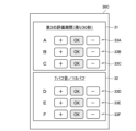
- FIG. 13 is a diagram for explaining an example of an evaluation setting screen.
- FIG. 13 is a diagram for explaining an example of an evaluation setting screen.
- FIG. 13 is a diagram for explaining an example of an evaluation setting screen.
- 11 is a sequence diagram showing an example of the flow of a customization process executed by the system according to the embodiment.
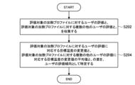
- FIG. 11 is a flowchart for explaining an example of a processing flow related to a first identification method of a user's evaluation tendency executed by the server according to the embodiment.
- 13 is a flowchart illustrating an example of a processing flow related to a second identification method of a user's evaluation tendency executed by the server according to the embodiment.
- 13 is a flowchart illustrating an example of a process flow for changing a heating profile based on an evaluation tendency, which is executed by the server according to the embodiment.
- elements having substantially the same functional configuration may be distinguished by adding different letters after the same reference numeral.
- multiple elements having substantially the same functional configuration may be distinguished as necessary, such as suction device 100A and suction device 100B.
- suction device 100A and suction device 100B are distinguished as necessary.
- suction device 100A and suction device 100B are simply be referred to as suction device 100.
- FIG. 1 is a diagram showing an example of the configuration of a system 1 according to the present embodiment.
- the system 1 includes a plurality of suction devices 100 (100A and 100B), a plurality of terminal devices 200 (200A and 200B), and a server 300.
- the inhalation device 100 is a device that generates a substance to be inhaled by a user.
- the substance generated by the inhalation device 100 is described as an aerosol.
- the inhalation device 100 is an example of an aerosol generating device that generates an aerosol.
- the substance generated by the inhalation device may be a gas.
- the inhalation device 100 can accommodate a stick-type substrate 150.
- the inhalation device 100 generates an aerosol using the accommodated stick-type substrate 150.
- the stick-type substrate 150 is an example of a substrate that contributes to the generation of an aerosol.
- the stick-type substrate 150 contains an aerosol source.
- the inhalation device 100 generates an aerosol by heating the accommodated stick-type substrate 150.
- the terminal device 200 is a device used by a user of the suction device 100.
- the terminal device 200 is associated with the suction device 100.
- the suction device 100 and the terminal device 200 may be paired in advance for wireless communication, or the fact that the users of the suction device 100 and the terminal device 200 are the same may be registered in advance in the server 300.
- the terminal device 200 may be any device such as a smartphone, a tablet terminal, a wearable device, or a PC (Personal Computer).
- the terminal device 200 may be a charger that charges the suction device 100.
- the server 300 is an information processing device that manages information on each device included in the system 1.
- the server 300 communicates with the terminal device 200 via the network 900.
- the server 300 communicates indirectly with the suction device 100 via the terminal device 200.
- the server 300 may perform various processes based on information collected from the suction device 100 via the terminal device 200.
- the server 300 may perform various processes based on user operations performed on the terminal device 200.
- System 1 includes multiple suction devices 100 and multiple terminal devices 200 used by multiple users.
- a user who uses suction device 100A and terminal device 200A is also referred to as user A.
- a user who uses suction device 100B and terminal device 200B is also referred to as user B.
- FIG. 2 is a schematic diagram showing a configuration example of the suction device 100.
- the suction device 100 includes a power supply unit 111, a sensor unit 112, a notification unit 113, a storage unit 114, a communication unit 115, a control unit 116, a heating unit 121, a storage unit 140, and a heat insulating unit 144.
- the power supply unit 111 stores power.
- the power supply unit 111 supplies power to each component of the suction device 100 under the control of the control unit 116.
- the power supply unit 111 may be configured, for example, by a rechargeable battery such as a lithium ion secondary battery.
- the sensor unit 112 acquires various information related to the suction device 100.
- the sensor unit 112 is configured with a pressure sensor such as a condenser microphone, a flow sensor, or a temperature sensor, and acquires values associated with suction by the user.
- the sensor unit 112 is configured with an input device such as a button or switch that accepts information input from the user.
- the notification unit 113 notifies the user of information.
- the notification unit 113 is composed of, for example, a light-emitting device that emits light, a display device that displays an image, a sound output device that outputs sound, or a vibration device that vibrates.
- the storage unit 114 stores various information for the operation of the suction device 100.
- the storage unit 114 is configured, for example, from a non-volatile storage medium such as a flash memory.
- the communication unit 115 is a communication interface capable of performing communication conforming to any wired or wireless communication standard.
- Such communication standards may include, for example, standards using Wi-Fi (registered trademark), Bluetooth (registered trademark), BLE (Bluetooth Low Energy (registered trademark)), NFC (Near Field Communication), or LPWA (Low Power Wide Area).
- the control unit 116 functions as an arithmetic processing unit and a control unit, and controls the overall operation of the suction device 100 in accordance with various programs.
- the control unit 116 is realized by an electronic circuit such as a CPU (Central Processing Unit) or a microprocessor.
- the storage section 140 has an internal space 141 and holds the stick-shaped substrate 150 while storing a part of the stick-shaped substrate 150 in the internal space 141.
- the storage section 140 has an opening 142 that connects the internal space 141 to the outside, and stores the stick-shaped substrate 150 inserted into the internal space 141 through the opening 142.
- the storage section 140 is a cylindrical body with the opening 142 and the bottom 143 as the bottom surface, and defines a columnar internal space 141.
- An air flow path that supplies air to the internal space 141 is connected to the storage section 140.
- An air inlet hole which is an air inlet to the air flow path, is arranged, for example, on the side of the suction device 100.
- An air outlet hole which is an air outlet from the air flow path to the internal space 141, is arranged, for example, on the bottom 143.
- the stick-type substrate 150 includes a substrate portion 151 and a mouthpiece portion 152.
- the substrate portion 151 includes an aerosol source.
- the aerosol source includes a flavor component derived from tobacco or non-tobacco.
- the aerosol source may include a medicine.
- the aerosol source may be, for example, a liquid such as a polyhydric alcohol such as glycerin and propylene glycol, and water, which includes a flavor component derived from tobacco or non-tobacco, or may be a solid containing a flavor component derived from tobacco or non-tobacco.
- the stick-type substrate 150 When the stick-type substrate 150 is held in the storage portion 140, at least a part of the substrate portion 151 is stored in the internal space 141, and at least a part of the mouthpiece portion 152 protrudes from the opening 142.
- the heating unit 121 generates aerosol by heating the aerosol source and atomizing the aerosol source.
- the heating unit 121 is configured in a film shape and is arranged to cover the outer periphery of the storage unit 140.
- the heating unit 121 generates heat, the substrate unit 151 of the stick-shaped substrate 150 is heated from the outer periphery, and an aerosol is generated.
- the heating unit 121 generates heat when power is supplied from the power supply unit 111.
- power may be supplied when the sensor unit 112 detects that the user has started inhaling and/or that specific information has been input. Power supply may be stopped when the sensor unit 112 detects that the user has stopped inhaling and/or that specific information has been input.
- the insulating section 144 prevents heat transfer from the heating section 121 to other components.
- the insulating section 144 is made of a vacuum insulating material or an aerogel insulating material.
- the configuration of the suction device 100 is not limited to the above, and various configurations such as those exemplified below are possible.
- the heating unit 121 may be configured in a blade shape and disposed so as to protrude from the bottom 143 of the storage unit 140 into the internal space 141. In that case, the blade-shaped heating unit 121 is inserted into the substrate 151 of the stick-shaped substrate 150 and heats the substrate 151 of the stick-shaped substrate 150 from the inside. As another example, the heating unit 121 may be disposed so as to cover the bottom 143 of the storage unit 140. Furthermore, the heating unit 121 may be configured as a combination of two or more of a first heating unit that covers the outer periphery of the storage unit 140, a blade-shaped second heating unit, and a third heating unit that covers the bottom 143 of the storage unit 140.
- the storage unit 140 may include an opening/closing mechanism such as a hinge that opens and closes a portion of the outer shell that forms the internal space 141. The storage unit 140 may then open and close the outer shell to accommodate the stick-shaped substrate 150 inserted into the internal space 141 while clamping it.
- the heating unit 121 may be provided at the clamping location in the storage unit 140, and may heat the stick-shaped substrate 150 while pressing it.
- the means for atomizing the aerosol source is not limited to heating by the heating unit 121.
- the means for atomizing the aerosol source may be induction heating.
- the suction device 100 has at least an electromagnetic induction source such as a coil that generates a magnetic field, instead of the heating unit 121.
- a susceptor that generates heat by induction heating may be provided in the suction device 100, or may be included in the stick-shaped substrate 150.
- the inhalation device 100 works in cooperation with the stick-shaped substrate 150 to generate an aerosol that is inhaled by the user. Therefore, the combination of the inhalation device 100 and the stick-shaped substrate 150 may be considered as an aerosol generation system.
- FIG. 3 is a block diagram showing an example of the configuration of the terminal device 200 according to this embodiment.
- the terminal device 200 includes an input unit 210, an output unit 220, a detection unit 230, a communication unit 240, a storage unit 250, and a control unit 260.
- the input unit 210 has a function of accepting input of various information.
- the input unit 210 may include an input device that accepts input of information from a user. Examples of the input device include a button, a keyboard, a touch panel, and a microphone.
- the input unit 210 may also include various sensors such as an image sensor.
- the output unit 220 has a function of outputting information.
- the output unit 220 may include an output device that outputs information to the user.
- Examples of output devices include a display device that displays information, a light-emitting device that emits light, a vibration device that vibrates, and a sound output device that outputs sound.
- An example of a display device is a display.
- An example of a light-emitting device is an LED (Light Emitting Diode).
- An example of a vibration device is an eccentric motor.
- An example of a sound output device is a speaker.
- the output unit 220 notifies the user of the information by outputting the information input from the control unit 260.
- the detection unit 230 has a function of detecting information related to the terminal device 200.
- the detection unit 230 may detect position information of the terminal device 200.
- the detection unit 230 receives a GNSS signal from a Global Navigation Satellite System (GNSS) satellite (for example, a GPS signal from a Global Positioning System (GPS) satellite) and detects position information consisting of the latitude and longitude of the device.
- GNSS Global Navigation Satellite System
- GPS Global Positioning System
- the detection unit 230 may detect the movement of the terminal device 200.
- the detection unit 230 includes a gyro sensor and an acceleration sensor, and detects angular velocity and acceleration.
- the communication unit 240 is a communication interface for transmitting and receiving information between the terminal device 200 and other devices.
- the communication unit 240 performs communication conforming to any wired or wireless communication standard.
- a communication standard for example, a standard using USB (Universal Serial Bus), Wi-Fi (registered trademark), Bluetooth (registered trademark), NFC (Near Field Communication), or LPWA (Low Power Wide Area) can be adopted.
- the storage unit 250 stores various information.
- the storage unit 250 is configured, for example, with a non-volatile storage medium such as a flash memory.
- the control unit 260 functions as a calculation processing unit or control unit, and controls the overall operation of the terminal device 200 according to various programs.
- the control unit 260 is realized by an electronic circuit such as a CPU (Central Processing Unit) or a microprocessor.
- the control unit 260 may include a ROM (Read Only Memory) that stores the programs and calculation parameters to be used, and a RAM (Random Access Memory) that temporarily stores parameters that change as appropriate.
- the terminal device 200 executes various processes based on the control of the control unit 260.
- the processing of information input by the input unit 210, the output of information by the output unit 220, the detection of information by the detection unit 230, the transmission and reception of information by the communication unit 240, and the storage and reading of information by the storage unit 250 are examples of processes controlled by the control unit 260.
- Other processes executed by the terminal device 200, such as the input of information to each component and processing based on information output from each component, are also controlled by the control unit 260.
- the functions of the control unit 260 may be realized using an application.
- the application may be pre-installed or may be downloaded.
- the functions of the control unit 260 may be realized by PWA (Progressive Web Apps).
- the server 300 includes a communication unit 310, a storage unit 320, and a control unit 330.
- the communication unit 310 is a communication interface for transmitting and receiving information between the server 300 and other devices.
- the communication unit 310 performs communication conforming to any wired or wireless communication standard.
- the storage unit 320 stores various information for the operation of the server 300.
- the storage unit 320 is configured with a non-volatile storage medium such as a hard disc drive (HDD) or a solid state drive (SSD).
- HDD hard disc drive
- SSD solid state drive
- the control unit 330 functions as a calculation processing device and a control device, and controls the overall operation of the server 300 according to various programs.
- the control unit 330 is realized by, for example, a CPU (Central Processing Unit) and electronic circuits such as a microprocessor.
- the control unit 330 may include a ROM (Read Only Memory) that stores the programs and calculation parameters to be used, and a RAM (Random Access Memory) that temporarily stores parameters that change as appropriate.
- the server 300 executes various processes based on the control of the control unit 330.
- the transmission and reception of information by the communication unit 310, and the storage and reading of information by the storage unit 320 are examples of processes controlled by the control unit 330.
- Other processes executed by the server 300 such as input of information to each component and processing based on information output from each component, are also controlled by the control unit 330.
- the control unit 116 controls the operation of the heating unit 121 based on the heating profile.
- the control of the operation of the heating unit 121 is achieved by controlling the power supply from the power supply unit 111 to the heating unit 121.
- the heating unit 121 heats the stick-shaped substrate 150 by using the power supplied from the power supply unit 111.
- the heating profile is control information for controlling the temperature at which the aerosol source is heated.
- the heating profile specifies parameters related to the temperature at which the aerosol source is heated.
- An example of the temperature at which the aerosol source is heated is the temperature of the heating unit 121.
- An example of the parameter related to the temperature at which the aerosol source is heated is the target value of the temperature of the heating unit 121 (hereinafter also referred to as the target temperature).
- the temperature of the heating unit 121 may be controlled to change according to the elapsed time from the start of heating.
- the heating profile includes information that specifies the time series transition of the target temperature.
- the heating profile may include parameters that specify the method of supplying power to the heating unit 121 (hereinafter also referred to as the power supply parameters).
- the power supply parameters include, for example, the voltage applied to the heating unit 121, ON/OFF of the power supply to the heating unit 121, or the feedback control method to be adopted.
- ON/OFF of the power supply to the heating unit 121 may be regarded as ON/OFF of the heating unit 121.
- the control unit 116 controls the operation of the heating unit 121 so that the temperature of the heating unit 121 (hereinafter also referred to as the actual temperature) changes in the same manner as the target temperature defined in the heating profile.
- the heating profile is typically designed to optimize the flavor experienced by the user when the user inhales the aerosol generated from the stick-shaped substrate 150. Therefore, by controlling the operation of the heating unit 121 based on the heating profile, the flavor experienced by the user can be optimized.
- the temperature control of the heating unit 121 can be realized, for example, by known feedback control.
- the feedback control may be, for example, PID control (Proportional-Integral-Differential Controller).
- the control unit 116 may supply power from the power supply unit 111 to the heating unit 121 in the form of pulses by pulse width modulation (PWM) or pulse frequency modulation (PFM).
- PWM pulse width modulation
- PFM pulse frequency modulation
- the control unit 116 can control the temperature of the heating unit 121 by adjusting the duty ratio or frequency of the power pulse in the feedback control.
- the control unit 116 may perform simple on/off control in the feedback control.
- control unit 116 may perform heating by the heating unit 121 until the actual temperature reaches the target temperature, interrupt heating by the heating unit 121 when the actual temperature reaches the target temperature, and resume heating by the heating unit 121 when the actual temperature becomes lower than the target temperature.
- the temperature of the heating section 121 can be quantified, for example, by measuring or estimating the electrical resistance value of the heating section 121 (more precisely, the heating resistor that constitutes the heating section 121). This is because the electrical resistance value of the heating resistor changes depending on the temperature.
- the electrical resistance value of the heating resistor can be estimated, for example, by measuring the amount of voltage drop in the heating resistor.
- the amount of voltage drop in the heating resistor can be measured by a voltage sensor that measures the potential difference applied to the heating resistor.
- the temperature of the heating section 121 can be measured by a temperature sensor such as a thermistor installed near the heating section 121.
- a heating session is a period during which power supply to the heating unit 121 is controlled based on a heating profile.
- the start of a heating session is the timing when heating based on the heating profile starts.
- the end of a heating session is the timing when a sufficient amount of aerosol is no longer generated.
- a heating session includes a pre-heating period in the first half and a puffable period in the second half.
- the puffable period is a period during which a sufficient amount of aerosol is expected to be generated.
- the pre-heating period is the period from the start of heating to the start of the puffable period. Heating performed during the pre-heating period is also referred to as pre-heating.
- the notification unit 113 may notify the user of information indicating the timing at which preheating will end. For example, the notification unit 113 may notify the user of information predicting the end of preheating before the end of preheating, or may notify the user of information indicating that preheating has ended at the timing at which preheating has ended.
- the notification to the user may be performed, for example, by lighting an LED or vibrating. The user may refer to such a notification and begin puffing immediately after preheating has ended.
- the notification unit 113 may notify the user of information indicating the timing when the puffing period will end. For example, the notification unit 113 may notify the user of information predicting the end of the puffing period before the end of the puffing period, or may notify the user of information indicating that the puffing period has ended at the timing when the puffing period has ended.
- the notification to the user may be performed, for example, by lighting an LED or vibrating. The user may refer to such a notification and continue puffing until the puffing period ends.
- FIG. 5 is a graph that shows a schematic example of a heating profile.
- the horizontal axis of graph 20 is time.
- the vertical axis of graph 20 is temperature.
- Line 21 shows the time series progression of the target temperature.
- a heating session may include an initial heating period, an intermediate temperature drop period, and a re-heating period, in that order.
- the initial heating period is a period in which the temperature of the heating unit 121 rises rapidly after the start of heating and is maintained at a high temperature.
- the intermediate temperature drop period is a period in which the temperature of the heating unit 121 drops after the initial heating period.
- the re-heating period is a period in which the temperature of the heating unit 121 rises again after the intermediate temperature drop period.
- the target temperature rises rapidly to around 300°C during the initial heating period, then drops to around 230°C during the intermediate temperature drop period, and then rises stepwise to around 260°C during the re-heating period.
- power supply to the heating unit 121 may be interrupted and heating may be turned off.
- the period from the start of heating to the middle of the initial temperature rise period is the pre-heating period, and the period from the middle of the initial temperature rise period to the end of the re-heating period is the puffable period.
- the system 1 repeatedly executes the customization process.
- the customization process is a process for customizing (i.e., changing) the heating profile.
- the system 1 changes the heating profile so as to improve the user's evaluation. Therefore, by repeating the customization process, the system 1 can gradually generate a heating profile that can provide an optimal user experience.
- the customization process is executed or controlled by each of the suction device 100, the terminal device 200, or the server 300.
- the customization process includes at least the steps of the inhalation device 100 generating an aerosol using a heating profile, setting an evaluation period, accepting an evaluation setting by the user, modifying the heating profile based on the set evaluation, and setting the modified heating profile in the inhalation device 100.
- the customization process can be repeatedly executed until a heating profile as intended by the user is generated. Each step included in the customization process will be described in detail below.
- the inhalation device 100 generates an aerosol by heating the stick-shaped substrate 150 based on a heating profile.
- the user inhales the aerosol generated by the inhalation device 100 and checks the comfort of inhalation.
- the user may perform multiple puffs during the heating session.
- the timing of puffing may be set in advance.
- the user puffs at the preset puff timing.
- the terminal device 200 acquires information indicating the progress of heating from the inhalation device 100 and prompts the user to puff at a predetermined timing during the heating session.
- the information indicating the progress of heating may include the elapsed time from the start of heating, or the temperature of the heating unit 121, etc.
- the terminal device 200 may acquire identification information of the heating profile used by the inhalation device 100 from the inhalation device 100 together with or prior to the information indicating the progress of heating. This makes it possible to appropriately determine the arrival of the puff timing even if the puff timing differs for each heating profile.
- the puff timing does not have to be set in advance.
- the inhalation device 100 may transmit information for identifying the actual puff timing to the terminal device 200.
- the information for identifying the puff timing may be information indicating how many puffs have been performed during the heating session, or information for identifying the puff timing based on the elapsed time from the start of heating.
- Information for identifying the puff timing may be transmitted together with information indicating the progress of heating.
- the terminal device 200 divides the heating session to set multiple evaluation periods.
- the evaluation period is a period that is subject to evaluation by the user. For example, the terminal device 200 sets the evaluation period based on identification information of the heating profile used by the suction device 100 and information indicating the progress of heating.
- the evaluation period may include multiple puff timings. That is, the user may set an evaluation for multiple puffs all at once.
- the puff timing here may be a preset puff timing or an actual puff timing. With this configuration, it is possible to roughly customize the heating profile. As a result, it is possible to reduce the burden on the user compared to setting an evaluation for each puff.
- the evaluation period may include one puff timing.
- the user may set an evaluation for each puff. With this configuration, it becomes possible to customize the heating profile in detail.
- the terminal device 200 may set the evaluation period based on the time that has elapsed since the start of heating. For example, the terminal device 200 may divide the puffable period into 30-second intervals and set multiple 30-second evaluation periods.
- the terminal device 200 may set the evaluation period based on the number of puff timings. For example, the terminal device 200 may divide the puffable period for each puff timing and set an evaluation period for each puff timing. With this configuration, it is possible to appropriately set the evaluation period even if the user's puff intervals are not uniform.
- the terminal device 200 may accept evaluation settings for multiple evaluation items. With this configuration, the heating profile can be changed based on evaluations from various perspectives.
- the terminal device 200 may set multiple evaluation periods for each of the multiple evaluation items. The terminal device 200 may then accept settings for evaluations for each evaluation item for the aerosol inhaled by the user during each of the multiple evaluation periods set for each of the multiple evaluation items. For example, the terminal device 200 may set an evaluation period for evaluation items A to C every 30 seconds, and an evaluation period for evaluation items D to F every puff. With this configuration, the evaluation period can be flexibly set for each evaluation item, making it easier to customize.
- the terminal device 200 accepts the settings of evaluations for the aerosols inhaled by the user in each of a plurality of evaluation periods.
- the terminal device 200 accepts the settings of evaluations for the aerosols inhaled by the user in the evaluation period set for each evaluation item.
- the evaluations set by the user are used to change the heating profile.
- accepting the evaluation settings may be regarded as accepting the setting of an instruction to change the heating profile (a change value of the target temperature described later).
- the terminal device 200 may, for example, display a UI (User Interface) screen (hereinafter also referred to as the rating setting screen) for accepting rating settings on a touch panel, and accept touch operations for setting ratings during the evaluation period.
- the rating setting screen may be displayed in real time according to the progress of heating. In that case, the user can set the rating in real time while puffing.
- the rating setting screen may also be displayed after the heating session has ended. In that case, the user can calmly set the rating.
- FIGS. 6 to 8 are diagrams for explaining an example of an evaluation setting screen.
- the screens transition in this order: evaluation setting screen 30A shown in FIG. 6, then evaluation setting screen 30B shown in FIG. 7, and then evaluation setting screen 30C shown in FIG. 8.
- the heating session includes 15 puff timings, and evaluation settings are accepted in real time in parallel with the progress of heating.
- the evaluation setting screen 30 (30A to 30C) includes an evaluation setting field 31 and an evaluation setting field 32.
- the evaluation setting field 31 accepts the setting of an evaluation for evaluation items A to C, for which an evaluation period including multiple puff timings is set.
- the evaluation setting field 32 accepts the setting of an evaluation for evaluation items D to F, for which an evaluation period including one puff timing is set, i.e., an evaluation period is set for each puff.
- An evaluation for evaluation item A can be set by selecting either the "+” button, the "OK” button, or the "-" button in the button group 33A for evaluation item A. The same applies to the button groups 33B to 33F for evaluation items B to F.
- the evaluation setting screen 30A is displayed when 20 seconds remain in the first evaluation period and the second puff of the total 15 puffs has been made.
- the evaluation setting screen 30B is displayed when 30 seconds remain in the second evaluation period and the fourth puff of the total 15 puffs has been made.
- the evaluation setting screen 30C is displayed when 30 seconds remain in the third evaluation period and the seventh puff of the total 15 puffs has been made.
- Evaluation item A may be the taste.
- the taste is a sensation that refers to the taste of the aerosol in general. The stronger the taste, the stronger the taste is evaluated, and the weaker the taste, the weaker the taste is evaluated.
- the "+” button in button group 33A is a button for setting that the taste is strong.
- the “OK” button in button group 33A is a button for setting that the taste is just right.
- the “-” button in button group 33A is a button for setting that the taste is weak. The user can set the evaluation of the taste by selecting any one of the "+", “OK", or "-” buttons included in button group 33A.
- Evaluation item B may be the amount of smoke.
- the amount of smoke is a sensation that refers to the amount of aerosol. The greater the amount of aerosol that reaches the user's mouth per puff, the greater the amount of smoke is evaluated to be, and the less the amount of aerosol that reaches the user's mouth per puff, the less the amount of smoke is evaluated to be.
- the "+” button in button group 33B is a button for setting a large amount of smoke.
- the "OK” button in button group 33B is a button for setting a just right amount of smoke.
- the "-” button in button group 33B is a button for setting a small amount of smoke. The user can set the evaluation of the amount of smoke by selecting any one of the "+", "OK", or "-” buttons included in button group 33B.
- Evaluation item C may be tobacco feel.
- the tobacco feel is a sensation that indicates how close the taste is to that of a cigarette. The closer the taste of the aerosol itself or the intensity of the taste is to that of a cigarette, the stronger the tobacco feel is evaluated. On the other hand, the more refreshing the aerosol taste is, due to factors such as a strong fruit or mint flavor, the weaker the tobacco feel is evaluated.
- the "+” button in button group 33C is a button for setting a strong tobacco feel.
- the "OK” button in button group 33C is a button for setting a just right tobacco feel.
- the "-” button in button group 33C is a button for setting a weak tobacco feel. The user can set the evaluation of the tobacco feel by selecting any one of the "+", “OK", or "-” buttons included in button group 33C.
- Evaluation item D may be the kick sensation.
- the kick sensation is a sensation that indicates the degree of stimulation to the throat. Typically, the higher the nicotine content in the aerosol, the stronger the kick sensation is evaluated to be.
- the "+” button in button group 33D is a button for setting a strong kick sensation.
- the "OK” button in button group 33D is a button for setting a just right kick sensation.
- the "-" button in button group 33D is a button for setting a weak kick sensation. The user can set the evaluation of the kick sensation by selecting any one of the "+” button, "OK” button, or "-” button included in button group 33D.
- Evaluation item E may be odor. Odor is a sensation that indicates the closeness to the odor of cigarettes. The closer the odor of the aerosol is to the odor of cigarettes, the stronger the odor is evaluated. On the other hand, the more refreshing the odor of the aerosol is, for example, due to a strong fruity or minty scent, the weaker the odor is evaluated.
- the "+” button in button group 33E is a button for setting a strong odor.
- the "OK” button in button group 33E is a button for setting an appropriate odor.
- the "-” button in button group 33E is a button for setting a weak odor. The user can set the odor evaluation by selecting one of the "+", “OK", or "-” buttons included in button group 33E.
- Evaluation item F may be the sensation of sucking.
- the sensation of sucking is the degree of stimulation to the entire oral cavity.
- the "+” button in button group 33F is a button for setting a strong sensation of sucking.
- the "OK” button in button group 33F is a button for setting a just right sensation of sucking.
- the "-” button in button group 33F is a button for setting a weak sensation of sucking. The user can set an evaluation of the sensation of sucking by selecting one of the "+", “OK” or "-” buttons in button group 33F.
- the terminal device 200 sets the heating profile changed based on the evaluation set by the user in the suction device 100. For example, the evaluation set by the user is transmitted to the server 300, and the heating profile is changed by the server 300. The terminal device 200 then receives the changed heating profile from the server 300 and transfers it to the suction device 100. When the suction device 100 receives the changed heating profile from the terminal device 200, it stores the changed heating profile. This is expected to result in an improvement in the user's evaluation the next time heating is performed.
- the server 300 changes the target temperature corresponding to the evaluation period based on the user's evaluation of the aerosol inhaled during that evaluation period. For example, the server 300 increases the target temperature during an evaluation period in which the smoking taste is evaluated as being weak, and decreases the target temperature during an evaluation period in which the smoking taste is evaluated as being strong. With this configuration, the heating profile can be changed to improve the user's evaluation.
- the server 300 changes the target temperature defined in the heating profile used by the suction device 100 based on a change value corresponding to the evaluation set by the user.
- the change value corresponding to the evaluation can be set for each evaluation item.
- Table 1 below shows an example of the change value of the target temperature corresponding to the evaluation of evaluation items A to F, which are displayed on the evaluation setting screens 30A to 30C shown in Figures 6 to 8.
- the server 300 when the "+” button is selected for evaluation item A, the server 300 lowers the target temperature by 30°C. This reduces the next smoking taste, and is expected to improve the user's evaluation.
- the server 300 raises the target temperature by 30°C. This increases the next smoking taste, and is expected to improve the user's evaluation.
- the server 300 does not change the target temperature. This allows the next smoking taste to remain the same as the previous time, and is expected to maintain the user's good evaluation. The same applies to the other evaluation items.
- the server 300 calculates the final change value of the target temperature for each evaluation period by integrating the change values of the target temperature corresponding to the evaluations set for multiple evaluation items in overlapping evaluation periods (e.g., evaluation periods including the same puff timing).
- the server 300 then changes the heating profile by modifying the target temperature for each evaluation period specified in the heating profile based on the change value of the final target temperature for each evaluation period.
- the integration method it is possible to adopt the average value, the median value, the change value with the maximum absolute value (i.e., the change value with the largest change range), or the change value with the minimum absolute value (i.e., the change value with the smallest change range) as the final change value.
- Table 2 shows a case where the change value with the maximum absolute value is adopted as the final change value.
- P indicates a heating profile
- E indicates a rating
- the numbers added after P and E indicate indexes corresponding to the number of times the customization process is repeated.
- the heating profile P1 and the rating E1 set for the heating profile P1 are input to the server 300, and the heating profile P2 is output.
- the heating profile P2 is a heating profile in which changes are made to the heating profile P1 to improve the parts of the rating E1 that are not good (e.g., bad ratings). This customization process is repeated while the heating profile generated in the previous customization process is used as an input to the server 300 in the next customization process.
- the input heating profile P100 is output as is from the server 300, as shown in Table 3 above. Then, the repetition of the customization process stops. In this way, the heating profile P100 is generated as intended by the user.
- FIG. 9 is a sequence diagram showing an example of the flow of a customization process executed by the system 1 according to this embodiment.
- the suction device 100, the terminal device 200, and the server 300 are involved in this sequence.
- the suction device 100 starts heating based on the heating profile (step S102).
- the suction device 100 transmits information indicating the start of heating to the terminal device 200 (step S104).
- the information indicating the start of heating may include the heating profile used by the suction device 100.
- the terminal device 200 displays an evaluation setting screen (step S106). For example, the terminal device 200 sets an evaluation period based on the heating profile used by the suction device 100. Then, the terminal device 200 displays the evaluation setting screen 30 illustrated in Figs. 6 to 8 based on the evaluation period that has been set.
- the suction device 100 transmits information indicating the progress of the heating to the terminal device 200 (step S108).
- the information indicating the progress of the heating may include the elapsed time from the start of heating, the temperature of the heating unit 121, etc.
- the terminal device 200 When the terminal device 200 receives the information indicating the progress of the heating, it updates the evaluation setting screen (step S110). For example, the terminal device 200 updates the remaining time of the evaluation period in the evaluation setting field 31 and the number of puffs in the evaluation setting field 32, and sets the buttons in the button groups 33A to 33F to an unselected state when the evaluation period begins.
- the terminal device 200 accepts the setting of the rating (step S112).
- the terminal device 200 accepts an operation to select one of the "+” button, the "OK” button, and the "-" button included in each of the button groups 33A to 33F.
- step S114 determines whether the heating session has ended. If it is determined that the heating session has not ended (step S114: NO), the process returns to step S108.
- the terminal device 200 transmits the evaluation results and the heating profile to the server 300 (step S116).
- the evaluation results include information for identifying the evaluation period for each evaluation item, and the evaluation set for each evaluation item and evaluation period.
- the server 300 changes the heating profile received from the terminal device 200 based on the evaluation results received from the terminal device 200 (step S118). For example, the server 300 calculates a final change value of the target temperature for each puff timing by integrating multiple change values of the target temperature corresponding to the evaluations set for multiple evaluation items for each puff timing, as exemplified in Table 2. The server 300 then changes the heating profile by changing the target temperature for each puff timing based on the final change value for each puff timing.
- the server 300 transmits the changed heating profile to the terminal device 200 (step S120).
- the terminal device 200 receives the changed heating profile from the server 300, it transfers the received changed heating profile to the suction device 100 (step S122).
- the suction device 100 receives the changed heating profile, it stores the received changed heating profile (step S124). As a result, in the next customization process, the stick-shaped substrate 150 will be heated based on the changed heating profile.
- the evaluation tendency is information indicating the degree of deviation between the evaluation of the user and the evaluation of a plurality of other users for the same aerosol. More simply, the evaluation tendency of a user is information indicating the degree of deviation of the evaluation of the user from the average evaluation of all users. For example, even with the same aerosol, one user may evaluate it as having a strong smoking taste, while another user may evaluate it as having a weak smoking taste.
- By identifying the evaluation tendency of the user it becomes possible to more appropriately interpret the evaluation of the user for the aerosol according to the evaluation tendency of the user.
- by customizing the heating profile according to the evaluation tendency of the user it becomes possible to reach the heating profile as intended by the user more quickly. In this way, it becomes possible to further improve the quality of the user experience.
- the system 1 executes a process for identifying a user's evaluation tendency.
- the process for identifying a user's evaluation tendency is executed or controlled by each of the suction device 100, the terminal device 200, or the server 300.
- the process for identifying a user's evaluation tendency includes a process for collecting user evaluations of the heating profile to be evaluated, and a process for identifying a user's evaluation tendency based on the collected user evaluations.
- the process for collecting user evaluations of the heating profile to be evaluated includes the inhalation device 100 generating an aerosol using the heating profile to be evaluated, setting an evaluation period, and accepting an evaluation setting by the user.
- the contents of these processes included in the process for collecting user evaluations of the heating profile to be evaluated are as described above with respect to the customization process. Below, the process for identifying a user's evaluation tendency based on the collected user evaluations will be described.
- the server 300 identifies the user's evaluation tendency based on the user's evaluation set for the aerosol generated by the inhalation device 100 based on the heating profile of the evaluation target.
- the heating profile of the evaluation target is a specific heating profile used to identify the user's evaluation tendency.
- the server 300 may identify the user's evaluation tendency based on the user's evaluation of the heating profile to be evaluated and the evaluations of multiple other users of the heating profile to be evaluated. For example, the server 300 accumulates the evaluations of multiple other users of the heating profile to be evaluated and calculates an average value. The server 300 then identifies the difference between the user's evaluation of the heating profile to be evaluated and the average value of the evaluations of the multiple other users as the user's evaluation tendency. Note that the change value of the target temperature corresponding to the evaluation may be used as the evaluation.
- a change value of the target temperature that takes continuous values such as “-30°C”, “ ⁇ 0°C”, and “+30°C” may be used as the user's evaluation.
- the server 300 may identify the user's evaluation tendency based on the user's evaluation of the heating profile to be evaluated, which was generated based on the evaluations of multiple other users.
- the heating profile to be evaluated may be a heating profile (hereinafter also referred to as a standard heating profile) that has been evaluated by multiple other users as being just right for all puff timings and all evaluation items.
- the server 300 identifies the user's evaluation of the standard heating profile as the user's evaluation tendency as is.
- the server 300 identifies the user's evaluation tendency regarding the smoking taste as "-30°C". This is because the average of the smoking taste evaluations of multiple other users for the standard heating profile is "just right (OK)", i.e., " ⁇ 0°C". With this configuration, it is possible to easily identify the user's evaluation tendency.
- the server 300 may identify the user's evaluation tendency in each of the multiple evaluation periods based on the evaluation set for each of the multiple evaluation periods set in the period (i.e., heating session) in which the inhalation device 100 executed the process of generating an aerosol based on the heating profile of the evaluation target. For example, if the evaluation period is set for each puff, the server 300 may identify the user's evaluation tendency for each puff. Specifically, if the user's evaluation of the smoking taste of the first puff is "strong (+)" or "-30°C" and the average evaluation of the smoking taste of the first puff by multiple other users is "-10°C", the server 300 identifies the user's evaluation tendency for the smoking taste of the first puff as "-20°C".
- the server 300 may identify the user's evaluation tendency for each of the multiple evaluation items based on the evaluation set for each of the multiple evaluation items. For example, the server 300 may identify the user's evaluation tendency for smoking taste based on the evaluation set for the smoking taste. The same applies to other evaluation items. With this configuration, it becomes possible to identify the user's evaluation tendency in detail. For example, it becomes possible to identify differences in evaluation tendency for each evaluation item, such as a tendency for users to evaluate the smoking taste as strong while tending to evaluate the smoke volume as weak.
- the process of collecting user evaluations for the heating profile of the evaluation target may be executed multiple times. Then, the user's evaluation tendency may be identified based on the multiple evaluations collected.
- the server 300 identifies the user's evaluation tendency based on the multiple evaluations acquired when the inhalation device 100 executes the process of generating aerosol based on the heating profile of the evaluation target multiple times. For example, if the process of collecting user evaluations for the heating profile of the evaluation target is executed three times, the server 300 treats the average value of the user's evaluations of the three times for the smoking taste of the first puff as the user's evaluation of the smoking taste of the first puff and identifies the user's evaluation tendency. With this configuration, it is possible to prevent the target temperature from being changed too much or too little due to fluctuations in the user's evaluation.
- Tables 4 to 6 show the evaluation for each puff set by the user for evaluation item A, and the average value of the three evaluations.
- Table 5 shows the average value of the evaluation for each puff set by multiple other users for evaluation item A.
- the server 300 calculates the difference between the average value shown in Table 4 and the average value shown in Table 5, thereby identifying the user's evaluation tendency shown in Table 6.
- FIG. 10 is a flowchart illustrating an example of the process flow for the first method for identifying a user's evaluation tendency executed by the server 300 according to this embodiment.
- the server 300 collects the user's evaluation of the heating profile to be evaluated and multiple other users' evaluations of the heating profile to be evaluated (step S202).
- the server 300 identifies the difference between the target temperature change value corresponding to the user's evaluation of the heating profile being evaluated and the average value of the target temperature change values corresponding to the evaluations of multiple other users of the heating profile being evaluated as the user's evaluation tendency (step S204).
- FIG. 11 is a flowchart illustrating an example of the process flow for the second method of identifying a user's evaluation tendency executed by the server 300 according to this embodiment.
- the server 300 collects users' evaluations of the standard heating profile (step S302).
- the server 300 identifies the change value of the target temperature corresponding to the user's evaluation of the standard heating profile as the user's evaluation tendency (step S304).
- the server 300 changes the heating profile based on the user's evaluation set for the aerosol generated by the inhalation device 100 based on the heating profile and the user's evaluation tendency.
- the server 300 changes the heating profile based on the evaluation set by the user in the customization process
- the server 300 changes the heating profile based on the user's evaluation tendency in addition to the user's evaluation.
- the heating profile can be changed after more appropriately interpreting the user's evaluation of the aerosol according to the user's evaluation tendency. Therefore, it is possible to more quickly reach the heating profile as intended by the user.
- the server 300 corrects the change value of the target temperature corresponding to the user's evaluation of the heating profile based on the user's evaluation tendency, and changes the heating profile based on the corrected change value of the target temperature.
- the server 300 may correct the change value corresponding to the user's evaluation in the opposite direction to the user's evaluation tendency. For example, if the user tends to evaluate the smoking taste as strong, the server 300 may correct the evaluation of the smoking taste to be lower.
- the server 300 may change the heating profile based on the evaluation set for each of a plurality of evaluation periods set in the period (i.e., heating session) in which the inhalation device 100 executed the process of generating an aerosol based on the heating profile, and the user's evaluation tendency for each evaluation period.
- the server 300 corrects the change value corresponding to the evaluation for each evaluation period based on the evaluation tendency for each evaluation period.
- the server 300 then changes the target temperature for each evaluation period based on the corrected change value for each evaluation period. For example, when the evaluation period is set for each puff, the server 300 corrects the change value corresponding to the evaluation for each puff based on the evaluation tendency for each puff, and changes the target temperature for each puff timing based on the corrected change value.
- the server 300 may change the heating profile based on multiple target temperature change values corresponding to multiple evaluations set for multiple evaluation items and the user's evaluation tendency for each evaluation item.
- the server 300 corrects the target temperature change value corresponding to the evaluation for each evaluation item based on the evaluation tendency for each evaluation item.
- the server 300 corrects the target temperature change value corresponding to the evaluation set for the smoking taste based on the user's evaluation tendency for the smoking taste. The same applies to the other evaluation items.
- the server 300 then changes the heating profile based on the corrected target temperature change value for each evaluation item. With this configuration, it is possible to appropriately change the heating profile even if the user's evaluation tendency differs for each evaluation item.
- Server 300 may integrate the corrected change values of the target temperature for each evaluation item, and change the heating profile based on the integrated change value of the target temperature.
- server 300 calculates the final change value of the target temperature for each evaluation period by integrating the corrected change values of the target temperature for each evaluation item in the overlapping evaluation periods. Then, server 300 changes the heating profile by changing the target temperature for each evaluation period specified in the heating profile based on the final change value of the target temperature for each evaluation period.
- the integration method for obtaining the final change value of the target temperature is as described above with reference to Table 2.
- the server 300 calculates the corrected change value of the target temperature to "-10°C" by subtracting the user's evaluation tendency for the first puff, "-10°C", from the target temperature change value "-20°C", which corresponds to the evaluation "+” set by the user for the first puff. This corresponds to correcting the evaluation to be lower because the user tends to evaluate evaluation item A as high/strong. The same applies for the second puff.
- the server 300 sets the corrected change value of the target temperature to " ⁇ 0°C" because the user's evaluation is "just right (OK)".
- the server 300 may correct the change value of the target temperature corresponding to the portion of the user's evaluation of the heating profile that is not good (e.g., bad evaluation) based on the user's evaluation tendency, and change the heating profile based on the change value of the corrected target temperature.
- the server 300 may change the target temperature of the puff timing that is evaluated as many/strong (+) or few/weak (-). With this configuration, it becomes possible to change the heating profile so as to improve the user's evaluation.
- the server 300 does not need to make corrections based on the user's evaluation tendency to the change value of the target temperature that corresponds to a good evaluation among the user's evaluations of the heating profile.
- the server 300 does not need to change the target temperature of a puff timing that is evaluated as just right (OK). With this configuration, it is possible to prevent a user's evaluation from worsening due to a change in the heating profile.
- the server 300 may weight the evaluation tendency before changing the heating profile. An example of this case will be described with reference to Table 9 below.
- the server 300 calculates a corrected change value of the target temperature of "-15°C” by subtracting a weighted evaluation tendency of "-5°C” obtained by multiplying the user's evaluation tendency of "-10°C” for the first puff by a coefficient of "0.5” from the change value of the target temperature of "-20°C” corresponding to the evaluation "+” set by the user for the first puff. The same applies for the second puff.
- the coefficients shown in Table 9 above correspond to the weights assigned to the evaluation trends.
- the server 300 may set different coefficients for each evaluation period and/or for each evaluation item.
- FIG. 12 is a flowchart for explaining an example of the process flow for changing the heating profile based on the evaluation tendency executed by the server 300 according to this embodiment.
- the process explained in this flow can be executed in step S118 shown in FIG. 9.
- the server 300 corrects the change value of the target temperature corresponding to the evaluation for each evaluation item and evaluation period based on the user's evaluation tendency for each evaluation item and evaluation period (step S402). For example, the server 300 corrects each of the multiple change values of the target temperature corresponding to the evaluation for each puff timing set for multiple evaluation items based on the user's evaluation tendency for each evaluation item and puff timing.
- the server 300 integrates the corrected change values of the target temperature for each evaluation period (step S404). For example, the server 300 calculates the final change value of the target temperature for each puff timing by integrating multiple corrected change values of the target temperature corresponding to the evaluations set for multiple evaluation items at overlapping puff timings.
- the server 300 changes the heating profile based on the change value of the final target temperature for each evaluation period (step S406). For example, the server 300 changes the target temperature for each puff timing based on the change value of the final target temperature for each puff timing.
- the server 300 generates a new heating profile (hereinafter also referred to as a changed heating profile) by changing the heating profile (hereinafter also referred to as a heating profile before change) based on an evaluation set by a user.
- the server 300 may generate the changed heating profile based on a trained generation model for generating a heating profile.
- the generation model outputs the changed heating profile.
- the generation model may be a model trained by a known machine learning technique such as a support vector machine (SVM) or a neural network.
- SVM support vector machine
- the server 300 may collect multiple pieces of training data and learn a generative model based on the collected multiple pieces of training data.
- the training data includes a combination of a first heating profile, an evaluation set for the first heating profile, and a second heating profile to be generated based on the first heating profile and the evaluation set for the first heating profile.
- the training data is a desirable combination of the pre-change heating profile and the evaluation set for the pre-change heating profile, which are inputs to the generative model, and the post-change heating profile, which is output from the generative model.
- the accuracy of the generative model corresponds to the accuracy of the heating profile generated using the generative model.
- the server 300 may collect training data while the customization process is repeated. For example, in the example shown in Table 3, the server 300 may collect training data including heating profile P1 as the first heating profile, evaluation E1, and heating profile P100 as the second heating profile.
- the server 300 may collect training data including information indicating the user's evaluation tendency. With such a configuration, it becomes possible to learn the generative model by taking into account the user's evaluation tendency. As a result, it becomes possible to improve the accuracy of the generative model.
- the server 300 may collect the user's evaluation tendency as training data.
- the server 300 may collect training data including the heating profile P1 as the first heating profile, the evaluation E1, the user's evaluation tendency, and the heating profile P100 as the second heating profile.
- the server 300 may collect evaluations corrected based on the user's evaluation tendency as training data. For example, in the example shown in Table 3, the server 300 may collect training data including heating profile P1 as the first heating profile, evaluation E1 corrected based on the user's evaluation tendency, and heating profile P100 as the second heating profile.
- the server 300 may correct the change value corresponding to the user's evaluation in the same direction as the user's evaluation tendency. For example, if the user tends to evaluate the smoking taste as strong, the server 300 may correct the evaluation of the smoking taste more strongly.
- this configuration it is possible to prevent the change range of the target temperature from being insufficient based on the user's modest evaluation. As a result, it is possible to prevent a situation in which the target temperature is changed only little by little and the heating profile as intended by the user is not easily reached.
- the processes performed by the terminal device 200 or the server 300 described in the above embodiment may be performed by any device.
- the evaluation period may be set by the server 300.
- the heating profile may be changed by the terminal device 200.
- the server 300 may change parameters related to the time of the heating profile. Examples of parameters related to the time of the heating profile include the length of time of the heating session, the length of time of the initial heating period, the intermediate heating period, and the re-heating period. Another parameter related to the time of the heating profile is the puff timing.
- the parameter related to the temperature at which the aerosol source is heated is the target temperature value of the heating unit 121, but the present disclosure is not limited to such an example.
- An example of the parameter related to the temperature at which the aerosol source is heated is the target electrical resistance value of the heating unit 121.
- the means for heating the aerosol source is induction heating
- an example of the parameter related to the temperature at which the aerosol source is heated, as specified in the heating profile is the target value of the susceptor temperature, or the electrical resistance value of the electromagnetic induction source, etc.
- the suction device 100 may be configured as a so-called liquid atomization type aerosol generator that generates an aerosol by heating and atomizing an aerosol source as a liquid.
- the technology disclosed herein can also be applied to liquid atomization type aerosol generators.
- each process such as setting the evaluation period, accepting the evaluation settings, and setting the changed heating profile in the suction device 100, is executed by the terminal device 200.
- the execution of these processes by the terminal device 200 may refer to the execution of these processes via a native application installed on the terminal device 200.
- the execution of these processes by the terminal device 200 may refer to the execution of these processes via a PWA (Progressive Web Apps) provided for the terminal device 200.
- the server 300 may execute these processes via a PWA provided for the terminal device 200.
- At least a part of the functional configuration of the suction device 100 in the above embodiment may be included in another device.
- a charging device that charges the suction device 100.
- the charging device has a mechanism that allows the suction device 100 to be attached and detached, and can charge the suction device 100 and transmit and receive information between the suction device 100 and the charging device when the suction device 100 is connected.
- the charging device may have a wireless communication function and may relay the transmission and reception of information between the suction device 100 and a device such as a smartphone.
- the charging device may have a memory function and may store information received from the suction device 100 or to be transmitted to the suction device 100.
- the combination of the suction device 100 and the charging device may be regarded as an aerosol generation system.
- at least a part of the functional configuration of the terminal device 200 described in the above embodiment may be included in another device such as a charging device that charges the suction device 100.
- the series of processes performed by each device described in this specification may be realized using software, hardware, or a combination of software and hardware.
- the programs constituting the software are stored in advance, for example, in a recording medium (more specifically, a non-transient storage medium readable by a computer) provided inside or outside each device.
- Each program is loaded into a RAM when executed by a computer that controls each device described in this specification, and executed by a processing circuit such as a CPU.
- the recording medium is, for example, a magnetic disk, an optical disk, a magneto-optical disk, a flash memory, etc.
- the computer program may be distributed, for example, via a network without using a recording medium.
- the computer may be an application-specific integrated circuit such as an ASIC, a general-purpose processor that executes functions by reading a software program, or a computer on a server used in cloud computing.
- ASIC application-specific integrated circuit
- ASIC application-specific integrated circuit
- CPU central processing unit
- CPU central processing unit
- server a server used in cloud computing.
- the series of processes performed by each device described in this specification may be distributed and processed by multiple computers.
- a control unit that, based on a user's evaluation set for an aerosol generated based on control information to be evaluated by an aspirator that generates an aerosol by heating an aerosol source based on control information defining parameters related to the temperature at which the aerosol source is heated, identifies a user's evaluation tendency that indicates the degree of deviation between the user's evaluation and evaluations of multiple other users for the same aerosol;
- An information processing device comprising: (2) The control unit identifies the evaluation tendency based on an evaluation by the user with respect to the control information to be evaluated and evaluations by a plurality of other users with respect to the control information to be evaluated. The information processing device according to (1).
- the control unit identifies the evaluation tendency of the user based on an evaluation by the user with respect to the control information of the evaluation target generated based on evaluations by the multiple other users.
- the information processing device according to (1) or (2).
- the control unit identifies the evaluation tendency of the user in each of a plurality of evaluation periods based on an evaluation set for each of the plurality of evaluation periods set in a period during which the inhalation device executed a process of generating an aerosol based on the control information of the evaluation target.
- the information processing device according to any one of (1) to (3).
- the control unit identifies the evaluation tendency of the user for each of a plurality of evaluation items based on the evaluation set for each of a plurality of evaluation items.
- the information processing device according to any one of (1) to (4).
- the control unit identifies the evaluation tendency of the user based on a plurality of evaluations acquired when the inhalation device executes a process of generating an aerosol based on the control information of the evaluation target a plurality of times.
- the information processing device according to any one of (1) to (5).
- Identifying a user's evaluation tendency which indicates the degree of deviation between the user's evaluation and the evaluations of multiple other users for the same aerosol, based on a user's evaluation set for an aerosol generated by an suction device that generates an aerosol by heating an aerosol source based on control information to be evaluated, and the user's evaluation tendency indicating the degree of deviation between the user's evaluation and the evaluations of multiple other users for the same aerosol; 2.
- An information processing method implemented by a computer comprising: (8) Computer, a control unit that, based on a user's evaluation set for an aerosol generated based on control information to be evaluated by an aspirator that generates an aerosol by heating an aerosol source based on control information defining parameters related to the temperature at which the aerosol source is heated, identifies a user's evaluation tendency that indicates the degree of deviation between the user's evaluation and evaluations of multiple other users for the same aerosol;
Landscapes
- Engineering & Computer Science (AREA)
- Computer Networks & Wireless Communication (AREA)
- Medicinal Preparation (AREA)
- User Interface Of Digital Computer (AREA)
Priority Applications (4)
| Application Number | Priority Date | Filing Date | Title |
|---|---|---|---|
| KR1020257019788A KR20250108713A (ko) | 2022-12-13 | 2022-12-13 | 정보 프로세싱 디바이스, 정보 프로세싱 방법 및 컴퓨터-판독 가능 매체에 저장된 프로그램 |
| JP2024563995A JPWO2024127503A1 (https=) | 2022-12-13 | 2022-12-13 | |
| PCT/JP2022/045867 WO2024127503A1 (ja) | 2022-12-13 | 2022-12-13 | 情報処理装置、情報処理方法、及びプログラム |
| EP22968415.4A EP4623737A1 (en) | 2022-12-13 | 2022-12-13 | Information processing device, information processing method, and program |
Applications Claiming Priority (1)
| Application Number | Priority Date | Filing Date | Title |
|---|---|---|---|
| PCT/JP2022/045867 WO2024127503A1 (ja) | 2022-12-13 | 2022-12-13 | 情報処理装置、情報処理方法、及びプログラム |
Publications (1)
| Publication Number | Publication Date |
|---|---|
| WO2024127503A1 true WO2024127503A1 (ja) | 2024-06-20 |
Family
ID=91484574
Family Applications (1)
| Application Number | Title | Priority Date | Filing Date |
|---|---|---|---|
| PCT/JP2022/045867 Ceased WO2024127503A1 (ja) | 2022-12-13 | 2022-12-13 | 情報処理装置、情報処理方法、及びプログラム |
Country Status (4)
| Country | Link |
|---|---|
| EP (1) | EP4623737A1 (https=) |
| JP (1) | JPWO2024127503A1 (https=) |
| KR (1) | KR20250108713A (https=) |
| WO (1) | WO2024127503A1 (https=) |
Citations (9)
| Publication number | Priority date | Publication date | Assignee | Title |
|---|---|---|---|---|
| JP2012216986A (ja) * | 2011-03-31 | 2012-11-08 | Panasonic Corp | 補聴器調整装置、補聴器調整方法、および補聴器調整用プログラム |
| WO2019104227A1 (en) | 2017-11-22 | 2019-05-31 | Juul Labs, Inc. | User interface and user experience for a vaporizer device |
| CN110179160A (zh) * | 2019-05-28 | 2019-08-30 | 筑思有限公司 | 用于电子烟的校准方法、口感调节方法及电子烟 |
| US20190289915A1 (en) * | 2018-03-23 | 2019-09-26 | National Concessions Group Inc. | Crowdsourced data for vaporizers |
| US20190380382A1 (en) * | 2018-06-18 | 2019-12-19 | Duo IQ Labs, LLC | Methods and systems for managing vapor distribution |
| JP2019219105A (ja) * | 2018-06-20 | 2019-12-26 | 日立グローバルライフソリューションズ株式会社 | 加熱調理器および加熱調理器の調理システム |
| JP2020118420A (ja) * | 2019-01-28 | 2020-08-06 | 富士工業株式会社 | 換気システム |
| JP2021532728A (ja) * | 2019-06-17 | 2021-12-02 | ケーティー・アンド・ジー・コーポレーション | エアロゾル生成装置及びエアロゾル生成物品 |
| JP2022160299A (ja) * | 2021-04-06 | 2022-10-19 | 東芝ライフスタイル株式会社 | 炊飯器システム |
Family Cites Families (1)
| Publication number | Priority date | Publication date | Assignee | Title |
|---|---|---|---|---|
| BR112014009281B1 (pt) | 2011-10-20 | 2021-08-03 | Happiest Baby, Inc | Dispositivo para acalmar/auxiliar o sono de uma criança |
-
2022
- 2022-12-13 JP JP2024563995A patent/JPWO2024127503A1/ja active Pending
- 2022-12-13 KR KR1020257019788A patent/KR20250108713A/ko active Pending
- 2022-12-13 WO PCT/JP2022/045867 patent/WO2024127503A1/ja not_active Ceased
- 2022-12-13 EP EP22968415.4A patent/EP4623737A1/en active Pending
Patent Citations (9)
| Publication number | Priority date | Publication date | Assignee | Title |
|---|---|---|---|---|
| JP2012216986A (ja) * | 2011-03-31 | 2012-11-08 | Panasonic Corp | 補聴器調整装置、補聴器調整方法、および補聴器調整用プログラム |
| WO2019104227A1 (en) | 2017-11-22 | 2019-05-31 | Juul Labs, Inc. | User interface and user experience for a vaporizer device |
| US20190289915A1 (en) * | 2018-03-23 | 2019-09-26 | National Concessions Group Inc. | Crowdsourced data for vaporizers |
| US20190380382A1 (en) * | 2018-06-18 | 2019-12-19 | Duo IQ Labs, LLC | Methods and systems for managing vapor distribution |
| JP2019219105A (ja) * | 2018-06-20 | 2019-12-26 | 日立グローバルライフソリューションズ株式会社 | 加熱調理器および加熱調理器の調理システム |
| JP2020118420A (ja) * | 2019-01-28 | 2020-08-06 | 富士工業株式会社 | 換気システム |
| CN110179160A (zh) * | 2019-05-28 | 2019-08-30 | 筑思有限公司 | 用于电子烟的校准方法、口感调节方法及电子烟 |
| JP2021532728A (ja) * | 2019-06-17 | 2021-12-02 | ケーティー・アンド・ジー・コーポレーション | エアロゾル生成装置及びエアロゾル生成物品 |
| JP2022160299A (ja) * | 2021-04-06 | 2022-10-19 | 東芝ライフスタイル株式会社 | 炊飯器システム |
Non-Patent Citations (1)
| Title |
|---|
| See also references of EP4623737A1 |
Also Published As
| Publication number | Publication date |
|---|---|
| JPWO2024127503A1 (https=) | 2024-06-20 |
| KR20250108713A (ko) | 2025-07-15 |
| EP4623737A1 (en) | 2025-10-01 |
Similar Documents
| Publication | Publication Date | Title |
|---|---|---|
| US20240423288A1 (en) | Information processing device, information processing method, and non-transitory computer readable medium | |
| US20250000170A1 (en) | Information processing device, information processing method, and non-transitory computer readable medium | |
| US20250000164A1 (en) | Aerosol generation system, control method, and non-transitory computer readable medium | |
| US20240427861A1 (en) | System and information processing method | |
| JP7689589B2 (ja) | 制御装置、吸引装置、及び制御方法 | |
| US20240292906A1 (en) | System and method | |
| WO2023112248A1 (ja) | エアロゾル生成システム、及び端末装置 | |
| WO2024127503A1 (ja) | 情報処理装置、情報処理方法、及びプログラム | |
| WO2024127504A1 (ja) | 情報処理装置、情報処理方法、及びプログラム | |
| EP4623734A1 (en) | Terminal device, information processing method, and program | |
| EP4635339A1 (en) | Information processing device, information processing method, and program | |
| EP4623732A1 (en) | Terminal device and information processing device | |
| WO2024127487A1 (ja) | 端末装置及び制御方法 | |
| WO2024127488A1 (ja) | 端末装置及び制御方法 | |
| JP7699294B2 (ja) | 情報処理装置、情報処理方法、及びプログラム | |
| EP4627952A1 (en) | Terminal device, information processing method, and program | |
| WO2024127485A1 (ja) | 情報処理装置、及び情報処理方法 | |
| WO2025104789A1 (ja) | 情報処理装置、情報処理方法及びプログラム | |
| WO2025154266A1 (ja) | 加熱情報設定方法、加熱情報設定システム、及びプログラム | |
| WO2025141884A1 (ja) | 吸引装置、制御方法、及びプログラム | |
| WO2024194927A1 (ja) | エアロゾル生成システム、制御方法及び非一時的な記憶媒体 |
Legal Events
| Date | Code | Title | Description |
|---|---|---|---|
| 121 | Ep: the epo has been informed by wipo that ep was designated in this application |
Ref document number: 22968415 Country of ref document: EP Kind code of ref document: A1 |
|
| WWE | Wipo information: entry into national phase |
Ref document number: 2024563995 Country of ref document: JP |
|
| WWE | Wipo information: entry into national phase |
Ref document number: 1020257019788 Country of ref document: KR |
|
| WWE | Wipo information: entry into national phase |
Ref document number: 2022968415 Country of ref document: EP |
|
| ENP | Entry into the national phase |
Ref document number: 2022968415 Country of ref document: EP Effective date: 20250627 |
|
| NENP | Non-entry into the national phase |
Ref country code: DE |
|
| WWP | Wipo information: published in national office |
Ref document number: 1020257019788 Country of ref document: KR |
|
| WWP | Wipo information: published in national office |
Ref document number: 2022968415 Country of ref document: EP |