WO2024122576A1 - 配線基板、配線基板を用いた電子部品実装用パッケージ、および電子モジュール - Google Patents
配線基板、配線基板を用いた電子部品実装用パッケージ、および電子モジュール Download PDFInfo
- Publication number
- WO2024122576A1 WO2024122576A1 PCT/JP2023/043635 JP2023043635W WO2024122576A1 WO 2024122576 A1 WO2024122576 A1 WO 2024122576A1 JP 2023043635 W JP2023043635 W JP 2023043635W WO 2024122576 A1 WO2024122576 A1 WO 2024122576A1
- Authority
- WO
- WIPO (PCT)
- Prior art keywords
- opening
- ground
- ground line
- conductor
- pair
- Prior art date
- Legal status (The legal status is an assumption and is not a legal conclusion. Google has not performed a legal analysis and makes no representation as to the accuracy of the status listed.)
- Ceased
Links
Images




Classifications
-
- H—ELECTRICITY
- H05—ELECTRIC TECHNIQUES NOT OTHERWISE PROVIDED FOR
- H05K—PRINTED CIRCUITS; CASINGS OR CONSTRUCTIONAL DETAILS OF ELECTRIC APPARATUS; MANUFACTURE OF ASSEMBLAGES OF ELECTRICAL COMPONENTS
- H05K1/00—Printed circuits
- H05K1/02—Details
-
- H—ELECTRICITY
- H10—SEMICONDUCTOR DEVICES; ELECTRIC SOLID-STATE DEVICES NOT OTHERWISE PROVIDED FOR
- H10W—GENERIC PACKAGES, INTERCONNECTIONS, CONNECTORS OR OTHER CONSTRUCTIONAL DETAILS OF DEVICES COVERED BY CLASS H10
- H10W70/00—Package substrates; Interposers; Redistribution layers [RDL]
- H10W70/60—Insulating or insulated package substrates; Interposers; Redistribution layers
-
- H—ELECTRICITY
- H10—SEMICONDUCTOR DEVICES; ELECTRIC SOLID-STATE DEVICES NOT OTHERWISE PROVIDED FOR
- H10W—GENERIC PACKAGES, INTERCONNECTIONS, CONNECTORS OR OTHER CONSTRUCTIONAL DETAILS OF DEVICES COVERED BY CLASS H10
- H10W76/00—Containers; Fillings or auxiliary members therefor; Seals
- H10W76/10—Containers or parts thereof
Definitions
- Patent Document 1 A conventional wiring board is described, for example, in Patent Document 1.
- the first signal conductor is located between the first ground conductor and the second ground conductor.
- the second signal conductor is located with a space from the first signal conductor and is located between the first ground conductor and the second ground conductor.
- the first ground conductor has a first ground line and a second ground line.
- the second ground line faces the first ground line across the first region in the second direction.
- the second ground conductor has a third ground line and a fourth ground line.
- the fourth ground line faces the third ground line across the first region in the second direction.
- the first signal conductor has a pair of first electrode portions, a first line portion, and a second line portion. The pair of first electrode portions face each other across the first region in the second direction.
- the first line portion is connected to one of the pair of first electrode portions and extends away from the first region.
- the second line portion is connected to the other of the pair of first electrode portions and extends away from the first region.
- the second signal conductor has a pair of second electrode portions, a third line portion, and a fourth line portion.
- the pair of second electrode portions face each other across the first region in the second direction.
- the third line portion is connected to one of the pair of second electrode portions and extends away from the first region.
- the fourth line portion is connected to the other of the pair of second electrode portions and extends away from the first region.
- the first ground conductor, the first signal conductor, the second signal conductor, and the second ground conductor are arranged in this order in the first direction.
- the first opening is located in a first portion of the first region that is located between the first signal conductor and the second signal conductor in the first direction.
- the distance in the second direction between a pair of first electrode portions and the distance in the second direction between a pair of second electrode portions are smaller than at least one of the distance in the second direction between the first ground line and the second ground line and the distance in the second direction between the third ground line and the fourth ground line.
- the dimension of the first opening in the second direction is greater than at least one of the distance in the second direction between the pair of first electrode portions and the distance in the second direction between the pair of second electrode portions.
- the dimension of the first opening in the second direction is smaller than at least one of the distance in the second direction between the first ground line and the second ground line and the distance in the second direction between the third ground line and the fourth ground line.
- the first opening extends at least between a pair of first electrode portions and between a pair of second electrode portions.
- the dimension of the first opening in the first direction is greater than the distance in the first direction between the first ground conductor and the second ground conductor.
- the insulator further has a second opening and a third opening.
- the second opening is at least partially located in the first region.
- the third opening is at least partially located in the first region.
- the second opening is located between the first ground line and the second ground line in the second direction, and is spaced apart from the first signal conductor in the first direction.
- the third opening is located between the third ground line and the fourth ground line in the second direction, and is spaced apart from the second signal conductor in the first direction.
- the first opening has a first connection portion and a second connection portion.
- the first connection portion is connected to the second opening.
- the first connection portion is located between the pair of first electrode portions in the second direction.
- the second connection portion is connected to the third opening.
- the second connection portion is located between the pair of second electrode portions in the second direction.
- the dimension of the first opening in the second direction is smaller than the dimension of the second opening in the second direction and the dimension of the third opening.
- the depth of the first opening is greater than at least one of the depth of the second opening and the depth of the third opening.
- the second opening is in contact with the first ground line and the second ground line in a plan view.
- the third opening is in contact with the third ground line and the fourth ground line in a plan view.
- the ground conductor portion further includes a third ground conductor located between the first signal conductor and the second signal conductor.
- the third ground conductor includes a fifth ground line and a sixth ground line.
- the sixth ground line faces the fifth ground line in the second direction across the first region.
- the distance in the second direction between the fifth ground line and the sixth ground line is greater than at least one of the distance in the second direction between the first ground line and the second ground line and the distance in the second direction between the third ground line and the fourth ground line.
- the package for mounting electronic components includes the wiring board described above in (1) to (13), a substrate, and a frame.
- the frame is located on the substrate.
- the wiring board is fixed to the frame.
- the electronic module includes the electronic component mounting package of (14) above, an electronic component, and a lid.
- the electronic component is housed in the electronic component mounting package and is electrically connected to the wiring board.
- the lid is joined onto the frame and is positioned to cover the inside of the electronic component mounting package.
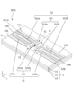
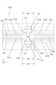
- FIG. 13 is a perspective view of a wiring board according to a second embodiment.
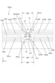
- FIG. 13 is a plan view of a wiring board according to a second embodiment.
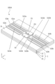
- FIG. 13 is a perspective view of a wiring board according to a third embodiment.
- FIG. 13 is a plan view of a wiring board according to a third embodiment.
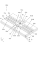
- FIG. 13 is a perspective view of a wiring board according to a fourth embodiment.
- FIG. 13 is a plan view of a wiring board according to a fourth embodiment.
- FIG. 13 is a plan view of a wiring board according to a fourth embodiment.
- FIG. 13 is a perspective view of a wiring board according to a fifth embodiment.
- FIG. 13 is a plan view of a wiring board according to a fifth embodiment.
- 12 is a cross-sectional view of the wiring board shown in FIG. 11 taken along the line XII-XII.
- FIG. 13 is an exploded perspective view of a wiring board according to a fifth embodiment.
- FIG. 13 is a perspective view of a wiring board according to a sixth embodiment.
- FIG. 13 is a plan view of a wiring board according to a sixth embodiment.
- FIG. 15 is an enlarged perspective view of a main part A shown in FIG. 14 .
- 1 is an exploded perspective view of an electronic component mounting package and an electronic module including a wiring board according to an embodiment
- 13 is a graph showing the reflection characteristics of wiring boards according to the fourth and fifth embodiments.
- 13 is a graph showing transmission characteristics of wiring boards according to the fourth and fifth embodiments.
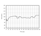
- 13 is a graph showing TDR (Time Domain Reflectometry) of wiring boards according to the fourth and fifth embodiments.
- a wiring board has a first ground pattern, a first wiring path, a second wiring path, a second ground pattern, a first pad pair, and a second pad pair on a ceramic base.
- the first pad pair is provided midway through the first wiring path.
- the second pad pair is provided midway through the second wiring path.
- the technology disclosed in Patent Document 1 describes a wiring board in which a capacitor is mounted on each of the first pad pair and the second pad pair.
- the bonding material may connect across the first and/or second pad pairs. This may result in electrical connection between the first and/or second pad pairs, causing a short circuit.
- any direction of the wiring board may be upward or downward, for convenience, a Cartesian coordinate system xyz is defined, and the positive side of the z direction is upward.
- a plan view is a concept including a planar perspective view.
- the first direction refers to, for example, the x direction in the drawings.
- the second direction refers to, for example, the y direction in the drawings.
- the third direction refers to, for example, the z direction in the drawings.
- the width, length, and thickness can be the dimensions in the x direction, the y direction, and the z direction, respectively.
- the wiring board 101A includes an insulator 1, a ground conductor portion G0, and a signal conductor portion S0.
- the insulator 1 has a first upper surface 1t.
- the first upper surface 1t has a first region 1s extending in a first direction (in other words, the x-direction).
- the first region 1s may be defined as a region sandwiched between a pair of first electrode portions S11 and a pair of second electrode portions S21, which will be described later. More specifically, the first region 1s may be a region extending in the x-direction from at least a first virtual line T1 connecting the outer edge of the first ground line G1a and the outer edge of the second ground line G1b to a second virtual line T2 connecting the outer edge of the third ground line G2a and the outer edge of the fourth ground line G2b.
- the first region 1s is rectangular, but may also be elliptical, or may be partially inclined in the y-direction.
- the material of the insulator 1 can be, for example, a ceramic material such as an aluminum oxide sintered body, a mullite sintered body, a silicon carbide sintered body, an aluminum nitride sintered body, or a silicon nitride sintered body, or a dielectric material such as a glass ceramic material or a glass epoxy material.
- a ceramic material such as an aluminum oxide sintered body, a mullite sintered body, a silicon carbide sintered body, an aluminum nitride sintered body, or a silicon nitride sintered body
- a dielectric material such as a glass ceramic material or a glass epoxy material.
- the insulator 1 may be a single layer, or may be configured with multiple insulating layers stacked together. In a plan view, the insulator 1 is, for example, rectangular, with dimensions of 4 mm x 4 mm to 50 mm x 50 mm, and a thickness of 0.5 mm to 10 mm. In one embodiment, the insulator 1 may be configured with a third insulating layer 13, a second insulating layer 12, and a first insulating layer 11 stacked in this order in the positive direction of the z-axis, as shown in FIG. 1, etc.
- the insulator 1 and the ground conductor portion G0 and signal conductor portion S0 described below may also be created by additive manufacturing (AM) using a 3D printer.
- AM additive manufacturing
- the insulator 1 can be manufactured, for example, as follows. A plurality of green sheets are processed using a mold or the like to prepare a plurality of green sheets formed to the outer shape of the insulator 1. Next, the plurality of green sheets are stacked so that their outer edges coincide to form a green sheet laminate. The green sheet laminate is fired to sinter the plurality of green sheets to obtain the insulator 1.
- the ground conductor portion G0 is located on the first upper surface 1t and extends in a second direction (in other words, the y direction) that intersects with the first direction.
- the ground conductor portion G0 has a first ground conductor G1 and a second ground conductor G2 that is spaced apart from the first ground conductor G1.
- ground conductor portion G0 examples include metal materials such as gold, silver, copper, nickel, tungsten, molybdenum, and manganese.
- the ground conductor portion G0 may be formed by sintering a metal paste onto the first upper surface 1t, or may be formed using a thin film formation technique such as a vapor deposition method or a sputtering method.
- the first ground conductor G1, the second ground conductor G2, and the third ground conductor G3 described below do not need to be made of the same material, and may be made of different materials.
- Metal plating such as nickel plating or gold plating may be formed on the surface of the ground conductor portion G0.
- an insulating film such as ceramic (e.g., an alumina coating) and/or resin may be further positioned on a portion of the ground conductor portion G0.
- the insulating film may be formed on the ground conductor portion G0 by screen printing. Furthermore, the insulating film may be positioned only on a portion of the ground conductor portion G0. With such a configuration, it is possible to reduce the possibility that the ground conductor portion G0 will short-circuit with other wiring.
- the first ground conductor G1 has a first ground line G1a and a second ground line G1b.
- the second ground line G1b faces the first ground line G1a across the first region 1s in the y direction.
- the first ground line G1a and the second ground line G1b are separated by the first region 1s.
- This state can also be said to mean that the first ground conductor G1 is cut by the first region 1s.
- the first ground line G1a and the second ground line G1b are linear, but may be partially curved.
- the first ground line G1a and the second ground line G1b are linearly symmetric across the first region 1s, but the first ground line G1a and the second ground line G1b may be different in shape.
- the first ground conductor G1 may be electrically connected to the inner layer ground conductor G4 by a via or the like. More specifically, the first ground line G1a and the second ground line G1b may each be electrically connected to the inner layer ground conductor G4 by a via or the like. In this case, the first ground line G1a and the second ground line G1b may be electrically connected via the inner layer ground conductor G4.
- the third ground line G2a and the fourth ground line G2b described below may also have the same or similar configuration as the first ground line G1a and the second ground line G1b.
- the second ground conductor G2 has a third ground line G2a and a fourth ground line G2b.
- the fourth ground line G2b faces the third ground line G2a across the first region 1s in the y direction. That is, the third ground line G2a and the fourth ground line G2b are separated by the first region 1s. In other words, this state may be said to be that the second ground conductor G2 is cut by the first region 1s.
- the third ground line G2a and the fourth ground line G2b are linear, but may be partially curved.
- the third ground line G2a and the fourth ground line G2b are linearly symmetrical with respect to the first region 1s, but the third ground line G2a and the fourth ground line G2b may be different in shape.
- the second line conductor G2 does not need to have the same shape as the first ground conductor G1, and may be different in shape.
- the width, length, and thickness of the first ground conductor G1 may be the same as or different from the width, length, and thickness of the second ground conductor G2.
- the signal conductor portion S0 is located on the first upper surface 1t and extends in the y direction.
- the material of the signal conductor portion S0 may be the same as or different from the material of the ground conductor portion G0, and may be, for example, the same or similar material as the material of the ground conductor portion G0 described above. Note that the signal conductor portion S0 and the ground conductor portion G0 do not necessarily need to be made of the same material, and may be different materials. Furthermore, the signal conductor portion S0 may be formed by the same or similar method as the ground conductor portion G0 described above.
- the signal conductor portion S0 has a first signal conductor S1 and a second signal conductor S2.
- the first signal conductor S1 and the second signal conductor S2 form a pair of differential signal lines. Compared to a single-ended signal line, a differential signal line can reduce the possibility of being affected by noise.
- the first signal conductor S1 is located between the first ground conductor G1 and the second ground conductor G2.
- the first signal conductor S1 has a pair of first electrode portions S11, a first line portion S12a, and a second line portion S12b.
- the pair of first electrode portions S11 face each other in the y direction with the first region 1s in between.
- the first line portion S12a is connected to one of the pair of first electrode portions S11, S11a, and extends away from the first region 1s.
- the second line portion S12b is connected to the other of the pair of first electrode portions S11, S11b, and extends away from the first region 1s.
- One S11a of the pair of first electrode portions S11 and the other S11b of the pair of first electrode portions S11 do not have to be symmetrical with respect to the first region 1s.
- the pair of first electrode portions S11 may have the same shape or different shapes.
- the width of the pair of first electrode portions S11 may be larger than the width of the first line portion S12a and the width of the second line portion S12b.
- the width of the pair of first electrode portions S11 may be the same as or different from the width of the first line portion S12a and the second line portion S12b.
- the relationship between the width of the pair of second electrode portions S21, the width of the third line portion S22a, and the width of the fourth line portion S22b, which will be described later, may also be the same as the above.
- the pair of first electrode portions S11 can be connected to electrical circuit elements such as capacitors, inductors, resistors, noise removal filters, and chip beads.
- the pair of first electrode portions S11 can be electrically connected to a first capacitor 31 as shown in FIG. 3. By connecting the first capacitor 31 to the pair of first electrode portions S11, the DC voltage component of the signal transmitted through the first signal conductor S1 can be reduced.
- the first capacitor 31 may be rectangular in plan view, with dimensions of 0.1 mm x 0.1 mm to 2 mm x 4 mm, and a height of 0.1 mm to 3 mm.
- the width of the first capacitor 31 may be greater than the width of the pair of first electrode portions S11 in plan view.
- the first capacitor 31 may contain, for example, forsterite, aluminum oxide, barium magnesium niobate, and barium neodymium titanate. More specifically, the first capacitor 31 may be a multi-layer ceramic capacitor (MLCC) or a silicon capacitor.
- MLCC multi-layer ceramic capacitor
- the second signal conductor S2 is located with a gap between it and the first ground conductor G1 and the second ground conductor G2.
- the second signal conductor S2 has a pair of second electrode portions S21, a third line portion S22a, and a fourth line portion S22b.
- the pair of second electrode portions S21 face each other in the y direction with the first region 1s in between.
- the third line portion S22a is connected to one of the pair of second electrode portions S21, S21a, and extends away from the first region 1s.
- the fourth line portion S22b is connected to the other of the pair of second electrode portions S21, S21b, and extends away from the first region 1s.
- An electric circuit element such as a capacitor, an inductor, or a resistor can be connected to the pair of second electrode parts S21.
- the electric circuit element connected to the pair of second electrode parts S21 may be the same as or different from the electric circuit element connected to the pair of first electrode parts S11.
- a second capacitor 32 can be electrically connected to the pair of second electrode parts S21 as shown in Fig. 3. By connecting the second capacitor 32 to the pair of second electrode parts S21, the DC voltage component of the signal transmitted through the second signal conductor S2 can be reduced.
- first electrode portions S11 and the pair of second electrode portions S21 may be collectively referred to as electrode portions.
- first capacitor 31 and the second capacitor 32 may be collectively referred to as electrical circuit elements.
- the first capacitor 31 can be connected to the pair of first electrode portions S11 by a bonding material.
- the second capacitor 32 can be connected to the pair of second electrode portions S21 by a bonding material.
- the bonding material for example, well-known solders such as Sn-Ag-Cu solder, Sn-Zn-Bi solder, Sn-Cu solder, etc. can be used.
- the first ground conductor G1, the first signal conductor S1, the second signal conductor S2, and the second ground conductor G2 are positioned in this order in the x direction.
- the first signal conductor S1 and the second signal conductor S2 are positioned between the first ground conductor G1 and the second line conductor G2 in the x direction.
- the insulator 1 has a first opening O1, at least a portion of which is located in the first region 1s.
- the first opening O1 may be formed by punching the insulator 1 before sintering, or by applying a known drilling process such as drilling, blasting, or laser processing to the insulator 1 after sintering.
- the first opening O1 is rectangular with rounded corners in a plan view, but the first opening O1 may be square or circular, including elliptical, in a plan view.
- the first opening O1 may penetrate the insulator 1.
- the first opening O1 is filled with at least one of the dielectric materials, such as air, a resin material, or a glass material, and has a lower dielectric constant than the insulator 1. This allows the characteristic impedance of the first signal conductor S1 and the second signal conductor S2 to be adjusted to a desired value when transmitting a high-frequency signal. This allows the loss of signal power that occurs in the first signal conductor S1 and the second signal conductor S2 to be reduced.
- the dielectric materials such as air, a resin material, or a glass material
- the first opening O1 is located in the first portion 1r located between the first signal conductor S1 and the second signal conductor S2 in the x direction in the first region 1s. Therefore, even if at least one of the amount of bonding material connecting the first capacitor 31 and the pair of first electrode portions S11 and the amount of bonding material connecting the second capacitor 32 and the pair of second electrode portions S21 increases, the excess bonding material can be kept within the first opening O1, reducing the possibility of the bonding materials coming into contact with each other and causing an electrical short circuit. Furthermore, this makes it possible to reduce the distance between the pair of electrode portions S11 and the pair of second electrode portions S21. Therefore, even when the electrical circuit elements are miniaturized together with the wiring board 101A, the electrical circuit elements can be stably mounted on the electrodes.
- At least a portion of the inner-layer ground conductor G4 may be located on the bottom surface of the first opening O1. In other words, at least a portion of the inner-layer ground conductor G4 may be exposed on the bottom surface of the first opening O1.
- the distance Ls1 in the y direction between the pair of first electrode parts S11 and the distance Ls2 in the y direction between the pair of second electrode parts S21 may be smaller than at least one of the distance Lg1 in the y direction between the first ground line G1a and the second ground line G1b and the distance Lg2 in the y direction between the third ground line G2a and the fourth ground line G2b. More specifically, the first ground conductor G1 and the second ground conductor G2 may not be located on at least a part of the side in the x direction of the pair of electrode parts S11 and the pair of second electrode parts S21.
- the impedance value is likely to be low in the pair of first electrode parts S11 to which the first capacitor 31 is connected and the pair of second electrode parts S21 to which the second capacitor 32 is connected. Therefore, by adopting the above-mentioned configuration, it is possible to reduce the possibility that the impedance value in the electrode parts will decrease. In addition, the above-mentioned configuration reduces the possibility that the protruding bonding material will come into contact with the first ground conductor G1 and/or the second ground conductor G2 when mounting an electrical circuit element on the electrode portion, causing a short circuit between the first signal conductor S1 and/or the second signal conductor S2.
- the dimension L1y in the y direction of the first opening O1 may be greater than at least one of the distance Ls1 in the y direction between the pair of first electrode portions S11 and the distance Ls2 in the y direction between the pair of second electrode portions S21. This reduces the possibility of the impedance value decreasing in the electrode portions where the impedance value is likely to be low when implementing electrical circuit elements. Note that the dimension L1y in the y direction of the first opening O1 refers to the maximum dimension of the first opening O1 in the y direction.
- first line portion S12a, the second line portion S12b, the third line portion S22a, and the fourth line portion S22b are not located to the sides of the first opening O1 in the x direction, but at least one of the first line portion S12a, the second line portion S12b, the third line portion S22a, and the fourth line portion S22 may be located to the sides of the first opening O1 in the x direction.
- the dimension L1y of the first opening O1 in the y direction may be smaller than at least one of the distance Lg1 between the first ground line G1a and the second ground line G1b in the y direction and the distance Lg2 between the third ground line G2a and the fourth ground line G2b in the y direction.
- the first ground line G1a and the second ground line G1b may be farther apart in the y direction than the dimension L1y of the first opening O1 in the y direction.
- the third ground line G2a and the fourth ground line G2b may be farther apart in the y direction than the dimension L1y of the first opening O1 in the y direction.
- the first ground conductor G1 and/or the second ground conductor G2 can be further away from the sides of the pair of electrode portions S11 and the pair of second electrode portions S21 in the x direction, thereby reducing the possibility of a decrease in the impedance value in the electrode portions.
- the ground conductor portion G0 may further include a third ground conductor G3 located between the first signal conductor S1 and the second signal conductor S2.
- the third ground conductor G3 may be sandwiched between the first signal conductor S1 and the second signal conductor S2.
- the third ground conductor G3 may have a fifth ground line G3a and a sixth ground line G3b.
- the fifth ground line G3a and the sixth ground line G3b are linear, but may also be partially curved.
- the sixth ground line G3b may face the fifth ground line G3a across the first region 1s in the y direction. This configuration can strengthen the ground potential around the signal conductor portion S0. This can reduce the possibility of resonance occurring in the first signal conductor S1 and the second signal conductor S2.
- the distance Lg3 in the y direction between the fifth ground line G3a and the sixth ground line G3b may be greater than at least one of the distance Lg1 in the y direction between the first ground line G1a and the second ground line G1b and the distance Lg2 in the y direction between the third ground line G2a and the fourth ground line G2b.
- the impedance value is likely to decrease in the space between the first signal conductor S1 and the second signal conductor S2 (particularly the pair of first electrode portions S11 and the pair of second electrode portions S21), but the above-mentioned configuration can reduce the possibility of the impedance value decreasing in the first signal conductor S1 and the second signal conductor S2.
- the first opening O1 may extend from at least between the pair of first electrode parts S11 to between the pair of second electrode parts S21. That is, the first opening O1 may be located under the first capacitor 31 and the second capacitor 32. Therefore, even if at least one of the amount of bonding material connecting the pair of first electrode parts S11 and the first capacitor 31 and the amount of bonding material connecting the pair of second electrode parts S21 and the second capacitor 32 is increased, the excess bonding material can be kept within the first opening O1, so that the possibility of the bonding materials coming into contact with each other and causing an electrical short circuit can be reduced. Furthermore, this makes it possible to reduce the distance between the pair of electrode parts S11 and the pair of second electrode parts S21. Therefore, even when the electric circuit element is miniaturized together with the wiring board 101B, the electric circuit element can be stably mounted on the electrode part.
- the depth of the first opening O1 may be shallow in part. That is, in a cross-sectional view perpendicular to the first surface 1t, the first opening O1 may have a stepped portion. Note that the depth referred to here may be the maximum dimension in the z direction from the first surface 1t to the bottom surface of the first opening O1. Also, in a cross-sectional view perpendicular to the first surface 1t, the bottom surface of the first opening O1 may have a curved shape that is convex in the negative direction of the z axis.
- the first opening O1 may have a portion extending in the positive direction of the x-axis beyond the space between the pair of first electrode portions S11. This portion may be regarded as a second opening O2 described later. In one embodiment, the first opening O1 may have a portion extending in the negative direction of the x-axis beyond the space between the pair of second electrode portions S21. This portion may be regarded as a third opening O3 described later.
- the dimension L1x in the x direction of the first opening O1 may be greater than the distance Lg12 in the x direction between the first ground conductor G1 and the second ground conductor G2.
- the distance Lg12 in the x direction between the first ground conductor G1 and the second ground conductor G2 refers to the smallest distance between the outer edge of the first ground conductor G1 and the outer edge of the second ground conductor G2.
- the insulator 1 may further have a second opening O2 and a third opening O3.
- the second opening O2 and the third opening O3 can be formed in the insulator 1 by the same or similar method as the first opening O1.
- the first opening O1, the second opening O2, and the third opening O3 may be collectively referred to as the openings.
- the second opening O2 may be at least partially located in the first region Is.
- the second opening O2 is located between the first ground line G1a and the second ground line G1b in the y direction, and is located with a space from the first signal conductor S1 in the x direction. In other words, the second opening O2 is sandwiched between the first ground line G1a and the second ground line G1b in the y direction.
- the second opening O2 is connected to the first opening O1, but the second opening O2 may be located with a space from the first opening O1. In other words, the second opening O2 and the first opening O1 do not have to be connected.
- the third opening O3 may be at least partially located in the first region Is.
- the third opening O3 is located between the third ground line G2a and the fourth ground line G2b in the y direction, and is spaced from the second signal conductor S2 in the x direction.
- the second opening O2 is sandwiched between the third ground line G2a and the fourth ground line G2b in the y direction.
- the third opening O3 is connected to the first opening O1, but the third opening O3 may be spaced from the first opening O1. In other words, the third opening O3 and the first opening O1 do not have to be connected.
- the pair of first electrode portions S11 are at least partially surrounded by the first opening O1 and the second opening O2 and the pair of second electrode portions S21 are at least partially surrounded by the first opening O1 and the third opening O3.
- excess bonding material when mounting the electrode portion and the electrical circuit element can be contained within the second opening O2 and/or the third opening O3. This reduces the possibility of the bonding materials coming into contact with each other and/or the possibility of the signal conductor portion S0 and the ground conductor portion G0 being electrically short-circuited by the bonding material.
- the first opening O1 may have a first connection portion O11 and a second connection portion O12.
- the first connection portion O11 may be connected to the second opening O2. Furthermore, the first connection portion O11 is located between the pair of first electrode portions S11 in the y direction. In other words, the region of the first opening O1 that is located between the pair of first electrode portions S11 in the y direction and where the first opening O1 and the second opening O2 are connected can be the first connection portion O11.
- the second connection portion O12 may be connected to the third opening O3. Furthermore, the second connection portion O12 is located between the pair of second electrode portions S21 in the y direction. In other words, the region of the first opening O1 that is located between the pair of second electrode portions S21 in the y direction and where the first opening O1 and the third opening O3 are connected can be the second connection portion O12.
- the above-described configuration effectively reduces the possibility of a drop in the impedance value in the pair of first electrode portions S11 and the pair of second electrode portions S21.
- the openings can be formed simultaneously, making it easy to manufacture the wiring board 101C.
- the dimension L1y in the y direction of the first opening O1 may be smaller than the dimension L2y in the y direction of the second opening O2 and the dimension L3y of the third opening O3. This allows the dimension L1y in the y direction of the first opening O1 to be a distance that matches the size of the electrical circuit element, effectively reducing the possibility of a decrease in impedance around the electrical circuit element without increasing the size of the wiring board 101C.
- the insulator 1 further has a second opening O2 and a third opening O3.
- the dimension L1y in the y direction of the first opening O1 may be larger than the dimension L2y in the y direction of the second opening O2 and the dimension L3y in the y direction of the third opening O3.
- the impedance value can be effectively adjusted by providing the openings, while the dimension L2y in the y direction of the second opening O2 and/or the dimension L3y in the y direction of the third opening O3 can be made smaller than the dimension L1y in the y direction of the first opening O1, thereby reducing the possibility of the strength of the insulator 1 decreasing.
- the dimension L2y in the y direction of the second opening O2 may be the same as or different from the dimension L3y in the y direction of the third opening O3.
- the first opening O1 may have a maximum dimension L1y in the y direction between the first signal conductor S1 and the second signal conductor S2.
- the dimension L11y in the y direction of the first connection portion O11 and the dimension L12y in the y direction of the second connection portion O12 may be smaller than the dimension L1y in the y direction of the first opening O1.
- the dimension L2y in the y direction of the second opening O2 and/or the dimension L3y in the y direction of the third opening O3 may be equal to or larger than the dimension L1y in the y direction of the first opening O1.
- the pair of first electrode portions S11 may be at least partially surrounded by the first opening O1 including the first connection portion O11 and the second opening O2.
- the pair of second electrode portions S21 may be at least partially surrounded by the first opening O1 including the second connection portion O12 and the third opening O3. This makes it possible to further reduce the volume of the insulator 1 around the electrode portions. This makes it possible to more effectively reduce the possibility of the impedance value decreasing in the first signal conductor S1 and the second signal conductor S2.
- the depth D1 of the first opening O1 may be deeper than at least one of the depth D2 of the second opening O2 and the depth D3 of the third opening O3.
- This configuration can reduce the possibility of the strength of the insulator 1 decreasing in the second opening O2 and/or the third opening O3 while further reducing the volume of the insulator 1 around the electrode portion where the impedance value may decrease.
- the depth here can be the maximum dimension in the z direction from the first surface 1t to the bottom surfaces of the first opening O1, the second opening O2, and the third opening O3.
- the bottom surfaces of the openings may have a curved shape that is convex in the negative direction of the z axis.
- the first opening O1 extends to the first insulating layer 11 and the second insulating layer 12, but the second opening O2 and the third opening O3 are located only in the first insulating layer 11. Note that the second opening O2 and the third opening O3 do not necessarily need to penetrate the first insulating layer 11. Moreover, the first opening O1 does not necessarily need to penetrate the first insulating layer 11 and the second insulating layer 12.
- the depth D1 of the first opening O1 may be shallower than at least one of the depth D2 of the second opening O2 and the depth D3 of the third opening O3.
- the impedance value may decrease between adjacent signal conductor portions S0. Therefore, the above configuration can reduce the possibility of the impedance value decreasing between adjacent signal conductor portions S0.
- the inner-layer ground conductor G4 may be located between the second insulating layer 12 and the third insulating layer 13. Also, as shown in FIG. 13, the inner-layer ground conductor G4 may have a lattice portion G4m.
- the lattice portion G4m is a portion in which through holes are provided in the inner-layer ground conductor G4, and the conductor is in a mesh shape. A part of the lattice portion G4m may be exposed at the bottom surface of the first opening O1. Also, at least a part of the electrode portion may be located at a position of the lattice portion G4m that overlaps with the through hole in a plan view. With this configuration, it is possible to stabilize the ground potential of the wiring board 101E while reducing the possibility of impedance reduction in the electrode portion.
- the second opening O2 may be in contact with the first ground line G1a and the second ground line G1b.
- the third opening O3 may be in contact with the third ground line G2a and the fourth ground line G2b. This configuration makes it even easier to adjust the impedance around the electrode portion.
- the second opening O2 may have a first cutout K1 at a position where it contacts the first ground line G1a, and a second cutout K2 at a position where it contacts the second ground line G1b.
- the third opening O3 may have a third cutout K3 at a position where it contacts the third ground line G2a, and a fourth cutout K4 at a position where it contacts the fourth ground line G2b.
- a conductor may be located on the inner surface of the first notch portion K1, the second notch portion K2, the third notch portion K3, and the fourth notch portion K4.
- the first notch portion K1, the second notch portion K2, the third notch portion K3, and the fourth notch portion K4 may be so-called castellations. This makes it possible to strengthen the ground potential in the wiring board 101F.
- ⁇ Simulation results> 18 is a graph showing the reflection characteristics of the wiring board 101 according to the fourth and fifth embodiments, with the horizontal axis showing the frequency (GHz) of the input signal and the vertical axis showing the reflection characteristics (dB). In addition, in the graph showing the reflection characteristics, the smaller the value of the reflection characteristics (dB), the smaller the reflection of the signal.
- the dashed line shows the characteristics of the fourth embodiment, and the solid line shows the characteristics of the fifth embodiment (the same applies to FIGS. 19 and 20 described later). It can be seen that both the fourth and fifth embodiments have good reflection characteristics in the range of 0 GHz to 110 GHz. Furthermore, it can be seen that the fifth embodiment has better characteristics than the fourth embodiment.
- FIG. 19 is a graph showing the pass characteristics of the wiring board 101 according to the fourth and fifth embodiments, with the horizontal axis showing the frequency (GHz) of the input signal and the vertical axis showing the pass characteristics (dB).
- the larger the pass characteristic (dB) value the smaller the signal loss. It can be seen that in the range of 0 GHz to 110 GHz, both the fifth and fourth embodiments provide good pass characteristics.
- FIG. 20 is a graph showing the TDR of the wiring board 101 according to the fourth and fifth embodiments, with the horizontal axis showing time (ps) and the vertical axis showing TDR (Ohm). It can be seen that both the fourth and fifth embodiments have good characteristics. Furthermore, it can be seen that the fifth embodiment has better characteristics than the fourth embodiment.
- an electronic component mounting package 10a includes a wiring substrate 101, a base 104, and a frame 102.
- the frame 102 is located on the base 104.
- the wiring substrate 101 is fixed to the frame 102.
- the wiring board 101 may have an input/output terminal portion 101a and a frame portion 101b.
- the wiring board 101 may also be connected to an external connection member by an adhesive.
- the input/output terminal portion 101a may be located outside the electronic component mounting package 10a.
- the input/output terminal portion 101a may be electrically connected to the signal conductor portion S0 and the ground conductor portion G0 of the wiring board 101, and may provide electrical continuity between the inside and outside of the electronic component mounting package 10a.
- the pair of first electrode portions S11 and the pair of second electrode portions S12 described above may be located inside the electronic component mounting package 10a.
- An external connection member may be connected to the input/output terminal portion 101a.
- the external connection member referred to here may be, for example, a flexible printed circuit (FPC), a printed circuit board (PCB) on which an electronic circuit is formed, or a metal member such as a lead terminal and/or a bonding wire.
- FPC flexible printed circuit
- PCB printed circuit board
- metal member such as a lead terminal and/or a bonding wire.
- the frame-shaped portion 101b may be partially joined to the frame body 102 described below. In other words, the inside of the electronic component mounting package 10a is surrounded by the frame-shaped portion 101b and the frame body 102.
- the wiring board 101 may be bonded to the upper surface of the base 104.
- the base 104 is, for example, rectangular in plan view, with a size of 10 mm ⁇ 10 mm to 50 mm ⁇ 50 mm and a thickness of 0.5 mm to 20 mm.
- Examples of the material of the base 104 include metal materials such as copper, iron, tungsten, molybdenum, nickel, and cobalt, and alloys containing these metal materials.
- the base 104 may be a single metal plate or a laminate of multiple metal plates.
- the material of the base 104 when the material of the base 104 is the above-mentioned metal material, a plating layer of nickel, gold, or the like may be formed on the surface of the base 104 by using an electroplating method or an electroless plating method in order to reduce oxidation corrosion.
- the material of the base 104 may be an insulating material, and may be, for example, a ceramic material such as an aluminum oxide sintered body, a mullite sintered body, a silicon carbide sintered body, an aluminum nitride sintered body, a silicon nitride sintered body, or a glass ceramic.
- the base 104 may be a PCB on which an electric circuit is printed. In this case, the wiring board 101 may be joined to the base 104 by a BGA.
- the frame 102 is located on the upper surface of the base 104, and protects the electronic components 103 located inside in a plan view. In other words, in a plan view, the frame 102 surrounds at least a portion of the periphery of the electronic components 103. The frame 102 does not have to surround the entire outer edge of the upper surface of the base 104. In one embodiment, the frame 102 is located along the outer edge of the upper surface of the base 104, but the frame 102 may be located inside the outer edge of the upper surface of the base 104.
- the frame body 102 may be rectangular in plan view.
- the wiring board 101 may be bonded to the lower surface of the frame body 102.
- the wiring board 101 may be sandwiched between the frame body 102 and the base body 104.
- the material of the frame 102 may be, for example, a metal material such as copper, iron, tungsten, molybdenum, nickel, or cobalt, or an alloy containing these metal materials.
- the material of the frame 102 may also be an insulating material, such as an aluminum oxide sintered body, a mullite sintered body, a silicon carbide sintered body, an aluminum nitride sintered body, a silicon nitride sintered body, or a ceramic material such as glass ceramics.
- the frame 102 can be joined to the base 104 via a brazing material or the like.
- the brazing material can be, for example, silver, copper, gold, aluminum, or magnesium, and may contain additives such as nickel, cadmium, or phosphorus.
- the frame 102 may have a through-hole portion 102a.
- a fixing member including a light-transmitting window member may be joined to the through-hole portion 102a.
- An optical fiber may be inserted and fixed in the fixing member.
- An electronic module 10 includes an electronic component mounting package 10a, an electronic component 103, and a lid 105.
- the electronic component 103 is located on a base 104 and is electrically connected to a wiring board 101.
- the lid 105 is located on a frame 102 and is positioned to cover the inside of the electronic component mounting package 10a.
- the wiring substrate 101 may be a wiring structure 100 connected to an external connection member via an adhesive.
- the electronic component 103 may be a component that performs signal processing, such as converting an optical signal into an electrical signal or an electrical signal into an optical signal.
- the electronic component 103 is located on the upper surface of the base 104 and is housed in the electronic component mounting package 10a.
- the electronic component 103 may be a component that performs signal processing, such as converting a radio signal or an optical signal into an electrical signal, or converting an electrical signal into a radio signal or an optical signal.
- the electronic component 103 may be directly bonded to the base 104.
- a seat containing a ceramic material and/or a metal material may be located between the electronic component 103 and the base 104. That is, the electronic component 103 may be indirectly bonded to the base 104.
- Examples of the electronic component 103 include optical semiconductor elements such as a semiconductor laser (LD: Laser Diode) or a photodiode (PD: Photodiode), semiconductor integrated circuit elements such as a field effect transistor (FET: Field Effect Transistor), and sensor elements such as an optical sensor.
- the electronic component 103 can be formed of a semiconductor material such as gallium arsenide or gallium nitride.
- the lid 105 is positioned on the frame 102, covering the inside of the electronic component mounting package 10a, and protects the electronic component 103 together with the frame 102.
- the lid 105 may be rectangular in plan view.
- the lid 105 may have a size of 10 mm x 10 mm to 50 mm x 50 mm and a thickness of 0.5 mm to 2 mm.
- materials for the lid 105 include metal materials such as iron, copper, nickel, chromium, cobalt, molybdenum, or tungsten, or alloys that combine multiple of these metal materials.
- the metal member that constitutes the lid 105 can be produced by subjecting an ingot of such a metal material to metal processing methods such as rolling and punching.
- the electronic module 10 may further include a seal ring located between the lid body 105 and the frame body 102.
- the seal ring has a function of joining the lid body 105 and the frame body 102.
- the seal ring is located on the frame body 102 and surrounds the electronic component 103 in a planar view.
- materials for the seal ring include metal materials such as iron, copper, silver, nickel, chromium, cobalt, molybdenum, and tungsten, or alloys combining a plurality of these metal materials. Note that if a seal ring is not provided on the frame body 102, the lid body 105 may be joined to the frame body 102 via an adhesive such as solder, brazing material, glass, or resin adhesive.
- This disclosure can be used as a wiring board, a package for mounting electronic components using a wiring board, and an electronic module.
Landscapes
- Engineering & Computer Science (AREA)
- Microelectronics & Electronic Packaging (AREA)
- Structure Of Printed Boards (AREA)
Priority Applications (1)
| Application Number | Priority Date | Filing Date | Title |
|---|---|---|---|
| JP2024562967A JPWO2024122576A1 (https=) | 2022-12-07 | 2023-12-06 |
Applications Claiming Priority (2)
| Application Number | Priority Date | Filing Date | Title |
|---|---|---|---|
| JP2022-195727 | 2022-12-07 | ||
| JP2022195727 | 2022-12-07 |
Publications (1)
| Publication Number | Publication Date |
|---|---|
| WO2024122576A1 true WO2024122576A1 (ja) | 2024-06-13 |
Family
ID=91379104
Family Applications (1)
| Application Number | Title | Priority Date | Filing Date |
|---|---|---|---|
| PCT/JP2023/043635 Ceased WO2024122576A1 (ja) | 2022-12-07 | 2023-12-06 | 配線基板、配線基板を用いた電子部品実装用パッケージ、および電子モジュール |
Country Status (2)
| Country | Link |
|---|---|
| JP (1) | JPWO2024122576A1 (https=) |
| WO (1) | WO2024122576A1 (https=) |
Citations (2)
| Publication number | Priority date | Publication date | Assignee | Title |
|---|---|---|---|---|
| JP2003179181A (ja) * | 2001-12-11 | 2003-06-27 | Ngk Spark Plug Co Ltd | 樹脂製配線基板 |
| WO2020040072A1 (ja) * | 2018-08-21 | 2020-02-27 | Ngkエレクトロデバイス株式会社 | 配線基板、パッケージおよびモジュール |
-
2023
- 2023-12-06 JP JP2024562967A patent/JPWO2024122576A1/ja active Pending
- 2023-12-06 WO PCT/JP2023/043635 patent/WO2024122576A1/ja not_active Ceased
Patent Citations (2)
| Publication number | Priority date | Publication date | Assignee | Title |
|---|---|---|---|---|
| JP2003179181A (ja) * | 2001-12-11 | 2003-06-27 | Ngk Spark Plug Co Ltd | 樹脂製配線基板 |
| WO2020040072A1 (ja) * | 2018-08-21 | 2020-02-27 | Ngkエレクトロデバイス株式会社 | 配線基板、パッケージおよびモジュール |
Also Published As
| Publication number | Publication date |
|---|---|
| JPWO2024122576A1 (https=) | 2024-06-13 |
Similar Documents
| Publication | Publication Date | Title |
|---|---|---|
| US10806033B2 (en) | Interposer and electronic device | |
| US7649252B2 (en) | Ceramic multilayer substrate | |
| WO2014171225A1 (ja) | 高周波部品およびこれを備える高周波モジュール | |
| JP6093020B2 (ja) | 素子収納用パッケージおよび実装構造体 | |
| US20250056726A1 (en) | Wiring board, electronic component mounting package using wiring board, and electronic module | |
| CN101523530A (zh) | 复合电气元件 | |
| WO2023145651A1 (ja) | 配線基板、配線基板を用いた電子部品実装用パッケージ、および電子モジュール | |
| JP5926290B2 (ja) | 入出力部材ならびに電子部品収納用パッケージおよび電子装置 | |
| US6936921B2 (en) | High-frequency package | |
| CN108781512A (zh) | 高频基板、高频封装件以及高频模块 | |
| WO2015088028A1 (ja) | 素子収納用パッケージおよび実装構造体 | |
| JPH11176987A (ja) | 高周波用電力増幅器 | |
| US20250351264A1 (en) | Wiring board, electronic component mounting package using wiring board, and electronic module | |
| WO2024122576A1 (ja) | 配線基板、配線基板を用いた電子部品実装用パッケージ、および電子モジュール | |
| JP7432703B2 (ja) | 配線基体および電子装置 | |
| JP7573040B2 (ja) | 配線基体および電子装置 | |
| JP7817435B2 (ja) | 配線基板、配線基板を用いた電子部品実装用パッケージ、および電子モジュール | |
| US12374608B2 (en) | Hybrid chip carrier package | |
| US20240292520A1 (en) | Matching circuit board and semiconductor device | |
| JP2024048912A (ja) | 配線基板、配線基板を用いた配線構造体、電子部品実装用パッケージ、および電子モジュール | |
| WO2024029628A1 (ja) | 配線基板、配線基板を用いた電子部品実装用パッケージおよび電子モジュール | |
| WO2024014433A1 (ja) | 配線構造体および電子モジュール | |
| JP5743870B2 (ja) | 配線基板および多数個取り配線基板 | |
| WO2025063160A1 (ja) | 配線構造体および電子モジュール | |
| WO2026048794A1 (ja) | 配線基板、電子部品収納用パッケージ及び電子モジュール |
Legal Events
| Date | Code | Title | Description |
|---|---|---|---|
| 121 | Ep: the epo has been informed by wipo that ep was designated in this application |
Ref document number: 23900688 Country of ref document: EP Kind code of ref document: A1 |
|
| WWE | Wipo information: entry into national phase |
Ref document number: 2024562967 Country of ref document: JP |
|
| NENP | Non-entry into the national phase |
Ref country code: DE |
|
| 122 | Ep: pct application non-entry in european phase |
Ref document number: 23900688 Country of ref document: EP Kind code of ref document: A1 |