WO2024121970A1 - 良否判定装置および良否判定方法 - Google Patents
良否判定装置および良否判定方法 Download PDFInfo
- Publication number
- WO2024121970A1 WO2024121970A1 PCT/JP2022/045088 JP2022045088W WO2024121970A1 WO 2024121970 A1 WO2024121970 A1 WO 2024121970A1 JP 2022045088 W JP2022045088 W JP 2022045088W WO 2024121970 A1 WO2024121970 A1 WO 2024121970A1
- Authority
- WO
- WIPO (PCT)
- Prior art keywords
- substrate
- image
- component
- machine
- teacher
- Prior art date
- Legal status (The legal status is an assumption and is not a legal conclusion. Google has not performed a legal analysis and makes no representation as to the accuracy of the status listed.)
- Ceased
Links
Images







Classifications
-
- H—ELECTRICITY
- H05—ELECTRIC TECHNIQUES NOT OTHERWISE PROVIDED FOR
- H05K—PRINTED CIRCUITS; CASINGS OR CONSTRUCTIONAL DETAILS OF ELECTRIC APPARATUS; MANUFACTURE OF ASSEMBLAGES OF ELECTRICAL COMPONENTS
- H05K13/00—Apparatus or processes specially adapted for manufacturing or adjusting assemblages of electric components
- H05K13/08—Monitoring manufacture of assemblages
- H05K13/083—Quality monitoring using results from monitoring devices, e.g. feedback loops
-
- G—PHYSICS
- G06—COMPUTING OR CALCULATING; COUNTING
- G06T—IMAGE DATA PROCESSING OR GENERATION, IN GENERAL
- G06T7/00—Image analysis
- G06T7/0002—Inspection of images, e.g. flaw detection
- G06T7/0004—Industrial image inspection
-
- G—PHYSICS
- G06—COMPUTING OR CALCULATING; COUNTING
- G06T—IMAGE DATA PROCESSING OR GENERATION, IN GENERAL
- G06T2207/00—Indexing scheme for image analysis or image enhancement
- G06T2207/20—Special algorithmic details
- G06T2207/20081—Training; Learning
-
- G—PHYSICS
- G06—COMPUTING OR CALCULATING; COUNTING
- G06T—IMAGE DATA PROCESSING OR GENERATION, IN GENERAL
- G06T2207/00—Indexing scheme for image analysis or image enhancement
- G06T2207/20—Special algorithmic details
- G06T2207/20084—Artificial neural networks [ANN]
-
- G—PHYSICS
- G06—COMPUTING OR CALCULATING; COUNTING
- G06T—IMAGE DATA PROCESSING OR GENERATION, IN GENERAL
- G06T2207/00—Indexing scheme for image analysis or image enhancement
- G06T2207/30—Subject of image; Context of image processing
- G06T2207/30108—Industrial image inspection
- G06T2207/30141—Printed circuit board [PCB]
Definitions
- This specification discloses technology relating to a quality determination device and a quality determination method.
- a CPU Central Processing Unit
- the CPU temporarily saves the image after the component is picked up and the image while the head is moving as normal images in the HDD (hard disk) of the management server.
- the image after the component is picked up and the image while the head is moving are then reclassified from normal images to abnormal images.
- the image finally classified as a normal image is used when editing component-related data (such as component shape data).
- a machine learning learning model will be generated using teacher images of objects to be placed on a board by a board-related processing machine, and the quality of the board-related processing performed by the board-related processing machine will be judged.
- the learning model is used as is, there is a possibility that the quality of the board-related processing will be erroneously judged.
- this specification discloses a quality determination device and a quality determination method that can reduce erroneous determinations of substrate-related work using a learning model.
- This specification discloses a quality determination device that includes an acquisition unit and a learning unit.
- the acquisition unit acquires, in a production environment in which the product boards are produced, teacher images to be used for machine learning, which are multiple images of objects placed on the board by a substrate-related operation machine that performs a specified substrate-related operation on the board to produce a product board.
- the learning unit uses the teacher images acquired by the acquisition unit to re-learn a quality determination model that is a learning model generated using the teacher images acquired in an environment different from the production environment and that determines the quality of the substrate-related operation performed by the substrate-related operation machine.
- This specification also discloses a quality determination method including an acquisition step and a learning step.
- the acquisition step acquires, in a production environment in which the product substrate is produced, a plurality of images of an object placed on the substrate by a substrate-related operation machine that performs a predetermined substrate-related operation on the substrate to produce a product substrate, and teacher images to be used for machine learning.
- the learning step uses the teacher images acquired in the acquisition step to re-learn a quality determination model that is a learning model generated using the teacher images acquired in an environment different from the production environment and that determines the quality of the substrate-related operation performed by the substrate-related operation machine.
- the quality determination device described above allows the quality determination model to be re-learned using teacher images acquired in the production environment where the product boards are produced. This reduces erroneous determinations of work on boards compared to when the quality determination model is used as is. What has been described above about the quality determination device also applies to the quality determination method.
- FIG. 1 is a configuration diagram showing an example of a production line.
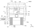
- FIG. 2 is a plan view showing a configuration example of a component mounting machine.
- FIG. 2 is a perspective view showing an example of a bulk feeder.
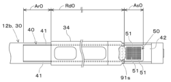
- FIG. 4 is a plan view seen in the direction of arrow IV in FIG. 3 .
- FIG. 11 is a plan view showing an example of a cavity unit to which components are supplied.
- FIG. 6 is a schematic diagram showing an example of a state in which components are accommodated in the three cavities in FIG. 5 .
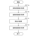
- FIG. 13 is a flowchart illustrating an example of a control procedure performed by an acquisition unit.
- FIG. 13 is a schematic diagram showing an example of a pre-mounting image.
- FIG. 13 is a schematic diagram showing an example of an image after mounting.
- FIG. 13 is a schematic diagram showing an example of relearning of a pass/fail determination model.
- Embodiment 1-1 Configuration example of production line WL0
- the quality determination device 80 can be applied to various production lines WL0 that produce product substrates 900.
- a substrate-related operation machine WM0 performs a predetermined substrate-related operation on a substrate 90 to produce the product substrate 900.
- the type and number of substrate-related operation machines WM0 are not limited.
- the production line WL0 of the embodiment includes a plurality (five) of substrate-related operation machines WM0, including a printer WM1, a print inspection machine WM2, a component mounting machine WM3, a reflow oven WM4, and a visual inspection machine WM5, and the substrate 90 is transported by a substrate transport device in the above order.
- the printer WM1 prints solder at the mounting position of the component 91 on the board 90.
- the print inspection machine WM2 inspects the printing condition of the solder printed by the printer WM1.
- the component mounting machine WM3 mounts multiple components 91 on the board 90 on which the solder has been printed by the printer WM1. There may be one component mounting machine WM3 or multiple component mounting machines WM3. When multiple component mounting machines WM3 are provided, multiple components 91 can be mounted by sharing the load between the multiple component mounting machines WM3.
- the reflow furnace WM4 heats the board 90 on which components 91 have been mounted by the component mounting machine WM3, melting the solder and performing soldering.
- the appearance inspection machine WM5 inspects the mounting state of the components 91 mounted by the component mounting machine WM3.
- the production line WL0 can use multiple (five) substrate-related work machines WM0 to transport the boards 90 in sequence and perform production processes including inspection processes to produce the product boards 900.
- the production line WL0 can also be equipped with substrate-related work machines WM0 such as functional inspection machines, buffer devices, substrate supply devices, substrate reversing devices, shield mounting devices, adhesive application devices, and ultraviolet ray irradiation devices as necessary.
- the multiple (five) substrate-related operation machines WM0 and the management device HC0 are connected to each other so that they can communicate with each other via a wired or wireless communication unit.
- the multiple (five) substrate-related operation machines WM0 and the management device HC0 form an on-site information and communication network (LAN: Local Area Network). This allows the multiple (five) substrate-related operation machines WM0 to communicate with each other via the communication unit.
- the multiple (five) substrate-related operation machines WM0 can also communicate with the management device HC0 via the communication unit.
- the management device HC0 controls the multiple (five) substrate-related work machines WM0 that make up the production line WL0, and monitors the operating status of the production line WL0.
- the management device HC0 stores various control data for controlling the multiple (five) substrate-related work machines WM0.
- the management device HC0 transmits control data to each of the multiple (five) substrate-related work machines WM0.
- each of the multiple (five) substrate-related work machines WM0 transmits its operating status and production status to the management device HC0.
- the management device HC0 is provided with a storage device 80s.
- the storage device 80s can store, for example, acquired data acquired by the substrate-related operation machine WM0 in relation to substrate-related operations. For example, image data of an image captured by the substrate-related operation machine WM0 is included in the acquired data.
- the teacher image 70 described below is included in the acquired data. Records (log data) of the operating status acquired by the substrate-related operation machine WM0 are included in the acquired data.
- the component mounting machine WM3 mounts a plurality of components 91 on a board 90. As shown in Fig. 2, the component mounting machine WM3 includes a board transport device 11, a component supply device 12, a component transfer device 13, a component camera 14, a board camera 15, and a control device 20.
- the board transport device 11 is, for example, a belt conveyor, and transports the board 90 in the transport direction (X-axis direction).
- the board 90 is a circuit board on which electronic circuits, electric circuits, magnetic circuits, etc. are formed.
- the board transport device 11 transports the board 90 into the component mounting machine WM3 and positions the board 90 at a predetermined position within the machine. After the component mounting machine WM3 has completed the mounting process of multiple components 91, the board transport device 11 transports the board 90 out of the component mounting machine WM3.
- the component supply device 12 supplies a plurality of components 91 to be mounted on the board 90.
- the component supply device 12 includes, for example, a plurality of feeders 12b arranged along the transport direction (X-axis direction) of the board 90. Each of the plurality of feeders 12b is detachably attached to the slot 12a.
- a tape feeder can be used for the feeder 12b. The tape feeder pitch-feeds a carrier tape containing the plurality of components 91, and supplies the components 91 at the supply position so that they can be picked up.
- the component camera 14 and the board camera 15 capture images based on control signals sent from the control device 20.
- Image data of the images captured by the component camera 14 and the board camera 15 is sent to the control device 20.
- the control device 20 is equipped with a known arithmetic device and storage device, and constitutes a control circuit. Information and image data output from various sensors provided in the component mounting machine WM3 are input to the control device 20.
- the control device 20 sends control signals to each device based on a control program and predetermined mounting conditions that have been set in advance.
- the control device 20 causes the board camera 15 to capture an image of the board 90 positioned by the board transport device 11.
- the control device 20 processes the image captured by the board camera 15 to recognize the positioning state of the board 90.
- the control device 20 also causes the part camera 14 to capture an image of the part 91 supplied by the part supply device 12.
- the control device 20 causes the holding member 13d to pick up and hold the part 91 supplied by the part supply device 12, and causes the part camera 14 to capture an image of the part 91 held by the holding member 13d.
- the control device 20 processes the image captured by the part camera 14 to recognize the supply state of the part 91 and the holding posture of the part 91.
- the control device 20 moves the holding member 13d toward above the intended mounting position that is set in advance by a control program or the like.
- the control device 20 also corrects the intended mounting position based on the positioning state of the board 90, the holding posture of the component 91, and the like, and sets the mounting position where the component 91 will actually be mounted.
- the intended mounting position and mounting position include a rotation angle in addition to the position (X-axis coordinate and Y-axis coordinate).
- the control device 20 corrects the target position (X-axis coordinates and Y-axis coordinates) and rotation angle of the holding member 13d to match the mounting position.
- the control device 20 lowers the holding member 13d at the corrected rotation angle in the corrected target position to mount the component 91 on the board 90.
- the control device 20 repeats the above pick-and-place cycle to perform the mounting process of mounting multiple components 91 on the board 90.
- the bulk feeder 30 supplies supply components 91s, which are a plurality of components 91 discharged from a component case 32, to the component mounting machine WM3.
- the bulk feeder 30 of the embodiment includes a feeder main body 31, a component case 32, a discharge device 33, a cover 34, a track member 40, a cavity unit 50, a vibration device 60, and a feeder control device 30c.
- the feeder main body 31 is formed in a flat box shape.
- the feeder main body 31 is detachably mounted in a slot 12a of the component supply device 12.
- a component case 32 that stores multiple components 91 in bulk is removably attached to the feeder body 31.
- the component case 32 can discharge the multiple components 91 stored therein.
- the component case 32 is an external device of the bulk feeder 30. For example, an operator selects a component case 32 that stores a component 91 to be used in the mounting process from among the multiple component cases 32, and attaches the selected component case 32 to the feeder body 31.
- the ejection device 33 adjusts the number of parts 91 ejected from the part case 32.
- the ejection device 33 ejects the supply parts 91s into the receiving area Ar0 of the track member 40 shown in FIG. 4.
- the supply parts 91s are part of the multiple parts 91 that are ejected from the part case 32 and supplied to the part mounting machine WM3.
- the cover 34 is removably attached to the upper tip side of the supply parts 91s in the transport direction. The cover 34 prevents the supply parts 91s transported along the transport path Rd0 of the track member 40 shown in FIG. 4 from scattering to the outside.
- the track member 40 has a transport path Rd0 along which supply parts 91s, which are multiple parts 91 discharged from the part case 32, are transported.
- the track member 40 is provided at the upper end of the transport direction of the supply parts 91s.
- the track member 40 is formed so as to extend in the transport direction of the supply parts 91s (left-right direction on the paper in FIG. 4).
- a pair of side walls 41, 41 that protrude upward are formed on both edges of the width direction of the transport path Rd0 (top-bottom direction on the paper in FIG. 4).
- the pair of side walls 41, 41, together with the tip 42 of the track member 40 surround the periphery of the transport path Rd0 and prevent leakage of the supply parts 91s transported along the transport path Rd0.
- the track member 40 has a receiving area Ar0, a supply area As0, and a transport path Rd0.
- the receiving area Ar0 is an area that receives supply parts 91s in bulk. In this embodiment, the receiving area Ar0 is provided below the discharge outlet of the part case 32.
- the supply area As0 is an area where the part mounting machine WM3 can pick up the supply parts 91s. Specifically, the supply area As0 is an area where the supply parts 91s can be picked up by the holding member 13d supported by the mounting head 13c, and is included in the movable range of the mounting head 13c.
- the cavity unit 50 has a plurality of cavities 51 (120 in this embodiment) in the supply area As0, each of which is to accommodate one of the supply parts 91s transported to the supply area As0.
- each of the plurality (120) cavities 51 is intended to accommodate one part 91.
- the plurality (120) cavities 51 are arranged in a matrix in the supply area As0.
- the cavity unit 50 has a total of 120 cavities 51, with 10 arranged in the transport direction of the supply parts 91s and 12 arranged in the width direction of the transport path Rd0.
- the track member 40 is provided so as to be vibrated relative to the feeder main body 31.
- the vibration device 60 vibrates the track member 40 to transport the supply parts 91s on the transport path Rd0 to the supply area As0 from which the component mounting machine WM3 can pick them up.
- the vibration device 60 causes the track member 40 to perform an elliptical motion clockwise or counterclockwise in a horizontal direction perpendicular to the transport direction of the supply parts 91s.
- the vibration device 60 vibrates the track member 40 so that an external force is applied to the supply parts 91s on the transport path Rd0 from the tip side in the supply direction (the right side of the paper in FIG. 4) and directed upward, or from the base side in the supply direction (the left side of the paper in FIG. 4) and directed upward.
- Whether the component mounting machine WM3 can pick up the component 91 supplied to the cavity unit 50 can be determined using machine learning. Specifically, as shown in the left diagram of FIG. 6, a machine learning learning model is generated using a teacher image 70 in which a component 91 housed in the cavity 51 in the correct orientation is captured, and the quality of the picking operation of the component 91 by the component mounting machine WM3 is determined. However, since there is a difference between the environment in which the teacher image 70 was acquired (e.g., the development environment) and the production environment in which the product board 900 is produced, if the learning model is used as is, there is a possibility that the quality of the picking operation will be erroneously determined.
- the environment in which the teacher image 70 was acquired e.g., the development environment
- the production environment in which the product board 900 is produced, if the learning model is used as is, there is a possibility that the quality of the picking operation will be erroneously determined.
- the production line WL0 is provided with a quality determination device 80.
- the quality determination device 80 re-learns the quality determination model 80m using teacher images 70 acquired in the production environment where the product boards 900 are produced. Therefore, erroneous determinations in the collection work are reduced compared to when the quality determination model 80m is used as is.
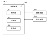
- the quality determination device 80 when considered as a control block, includes an acquisition unit 81 and a learning unit 82.
- the quality determination device 80 can also include a memory unit 83.
- the quality determination device 80 of the embodiment includes an acquisition unit 81, a learning unit 82, and a storage unit 83. At least one of the acquisition unit 81, the learning unit 82, and the storage unit 83 can be provided in various control devices, management devices, etc. At least one of the acquisition unit 81, the learning unit 82, and the storage unit 83 can also be formed on the cloud. In the embodiment, the acquisition unit 81, the learning unit 82, and the storage unit 83 are all provided in the management device HC0.
- the acquisition unit 81 acquires teacher images 70 in a production environment in which the product substrate 900 is produced (step S11 shown in FIG. 8).
- the teacher images 70 refer to images used for machine learning, which are a plurality of images capturing an object 91t provided on the substrate 90 by a substrate-related operation machine WM0 that performs a predetermined substrate-related operation on the substrate 90 to produce the product substrate 900.
- the control device 20 of the component mounting machine WM3 can make the above-mentioned correction during mounting and mount the component 91.
- the control device 20 judges the actual work on the board (the work of mounting the component 91) to be defective.
- the mounting of the component 91 is performed by the control device 20 of the component mounting machine WM3 (step S11c shown in FIG. 9).
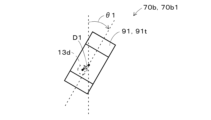
- the post-mounting image 70b2 can also be acquired by the visual inspection machine WM5.
- the visual inspection machine WM5 can judge the quality of the actual work on the board (the work of mounting the component 91) in the same way as the component mounting machine WM3.
- the component mounting machine WM3 of the embodiment includes a bulk feeder 30.
- the bulk feeder 30 includes a track member 40 and a vibration device 60.
- the track member 40 includes a transport path Rd0 along which a supply part 91s, which is a part 91 discharged from a part case 32 that contains the parts 91 in bulk, is transported to a supply area As0 where the supply part 91s can be picked up by the component mounting machine WM3.
- the vibration device 60 vibrates the track member 40 to transport the supply part 91s to the supply area As0.
- the pre-picking image 70a is an image of the supply component 91s transported to the supply area As0 of the bulk feeder 30.
- the pre-picking image 70a shown in the left diagram of FIG. 6 can be acquired, for example, by the board camera 15 of the component mounting machine WM3 (step S11a shown in FIG. 9).
- the component 91 is accommodated in the cavity 51 in the correct orientation, and the actual substrate work (the supply work of the component 91) is good.
- the acquisition unit 81 acquires the pre-picking image 70a as the teacher image 70 if the actual substrate work when acquiring the pre-picking image 70a, the pre-mounting image 70b1, and the post-mounting image 70b2 are all good.
- the control device 20 may erroneously recognize that one component 91 is housed in one cavity 51, and erroneously determine that the actual substrate work (the supply work of the components 91) is good.
- the holding member 13d it is difficult for the holding member 13d to pick up the component 91 housed in the cavity 51, and it is highly likely that the actual substrate work when the before-mounting image 70b1 and the after-mounting image 70b2 are acquired will be judged to be poor.
- the image shown in the right diagram in FIG. 6 is not adopted as the teacher image 70, and erroneous acquisition of the teacher image 70 is suppressed.
- the bulk feeder 30 of the embodiment also includes a cavity unit 50.
- the pick-up position of the part 91 by the holding member 13d is fixed to the position of the cavity 51.
- the bulk feeder 30 may also omit the cavity unit 50.
- the pick-up position of the part 91 by the holding member 13d is any position in the supply area As0, and the control device 20 needs to recognize the position and rotation angle of the part 91.
- the pass/fail judgment device 80 can be applied to either form.
- the storage unit 83 stores the teacher image 70 acquired by the acquisition unit 81 in the storage device 80s (step S12 shown in FIG. 8). This allows the storage device 80s to store and accumulate the teacher images 70 acquired in the production environment in which the product boards 900 are produced.
- the storage unit 83 may take various forms as long as it is capable of storing the teacher images 70 in the storage device 80s. For example, the storage unit 83 may store the teacher images 70 in the storage device 80s sequentially each time the acquisition unit 81 acquires a teacher image 70. Furthermore, when a predetermined number of teacher images 70 are acquired by the acquisition unit 81, the storage unit 83 may store the predetermined number of teacher images 70 collectively in the storage device 80s.
- the storage device 80s is required to be capable of storing at least the teacher image 70, and a known storage device, database, etc. may be used. Furthermore, at least when the object 91t is different, the applicable teacher image 70 is different. For example, when the object 91t is a component 91, when the component type is different, the applicable teacher image 70 is different. Therefore, the storage device 80s can store identification information for identifying the object 91t in association with the teacher image 70. Furthermore, for example, when the substrate-related work machine WM0 is different due to individual differences in the substrate-related work machine WM0, the appropriate teacher image 70 may also be different. Differences in the substrate-related work machine WM0 include differences in the devices and equipment (for example, the component supply device 12 of the component mounting machine WM3) that the substrate-related work machine WM0 is equipped with.
- the appropriate teacher image 70 may differ if the imaging device 80c is different. For example, if the lighting device of the imaging device 80c is different, the appropriate teacher image 70 may differ. Also, if the imaging conditions when the imaging device 80c captures the teacher image 70 are different, the appropriate teacher image 70 may differ. For example, if at least one of the lighting direction, exposure time, and aperture of the imaging device 80c is different, the appropriate teacher image 70 may differ.
- the storage device 80s may therefore store, in association with the teacher image 70, identification information identifying the target object 91t, identification information identifying at least one of the substrate-related operation machine WM0, the imaging device 80c that acquires the teacher image 70, and the imaging conditions under which the imaging device 80c acquired the teacher image 70. This allows the storage device 80s to store the teacher image 70 that matches the production environment.
- the component camera 14, board camera 15, and imaging devices of the component mounting machine WM3 and the visual inspection machine WM5 described above are included in the imaging device 80c.
- a manufacturer of the substrate-related operation machine WM0 may prepare teacher images 70 in advance, generate a machine learning learning model, and distribute the learning model to a user of the substrate-related operation machine WM0. This allows the user of the substrate-related operation machine WM0 to omit the work of acquiring teacher images 70 and generating a learning model.
- the target object 91t is a component 91
- the external dimensions of the component 91 may differ slightly if the vendor is different. This may result in a different teacher image 70, and the learning model generated by the manufacturer may be an inappropriate learning model.
- the environment in which the manufacturer acquired the teacher image 70 e.g., the development environment
- the production environment in which the user produces the product board 900 e.g., the production environment in which the user produces the product board 900
- the learning unit 82 uses the teacher images 70 acquired by the acquisition unit 81 to re-learn the pass/fail judgment model 80m, which is a learning model generated using the teacher images 70 acquired in an environment different from the production environment and judges whether the substrate-related operation performed by the substrate-related operation machine WM0 is pass/fail.
- the manufacturer of the substrate-related operation machine WM0 acquires the teacher images 70 in a development environment and generates the pass/fail judgment model 80m.
- the pass/fail judgment model 80m only needs to be able to judge whether the work on the substrate is pass/fail, and a publicly known learning model can be used.
- the pass/fail judgment model 80m can be generated in accordance with various machine learning algorithms such as a support vector machine and a neural network.
- the acquisition unit 81 acquires the teacher image 70 in the production environment in which the product substrate 900 is produced.
- the learning unit 82 uses the teacher image 70 acquired by the acquisition unit 81 to re-learn the pass/fail judgment model 80m.
- the learning unit 82 can re-learn the pass/fail judgment model 80m at any timing.
- the learning unit 82 can also re-learn the pass/fail judgment model 80m at a predetermined timing (if Yes in step S13 and step S14 shown in FIG. 8). For example, immediately after the substrate-related operation machine WM0 is introduced, the number of teacher images 70 acquired in the production environment is small, and re-learning of the pass/fail judgment model 80m may not be performed appropriately.
- the learning unit 82 can therefore re-learn the pass/fail determination model 80m when a predetermined time has passed since the substrate-related operation machine WM0 was introduced and production of the product substrate 900 was started. This allows the learning unit 82 to re-learn the pass/fail determination model 80m using the teacher images 70 acquired during the production of the product substrate 900 for the predetermined time, at the timing when a predetermined time has passed since the substrate-related operation machine WM0 was introduced and production of the product substrate 900 was started.
- the predetermined time can be set to any time, and can be set to a time at which re-learning of the pass/fail determination model 80m can be appropriately executed.
- the learning unit 82 can re-learn the pass/fail judgment model 80m using only the teacher images 70 acquired by the acquisition unit 81.
- the learning unit 82 can also re-learn the pass/fail judgment model 80m using a combination of teacher images 70 acquired by the acquisition unit 81 in the production environment and teacher images 70 acquired in an environment different from the production environment (e.g., a development environment).
- the learning unit 82 can also re-learn the pass/fail judgment model 80m by increasing the proportion of teacher images 70 acquired by the acquisition unit 81 as the above-mentioned specified time becomes longer.
- the learning unit 82 can re-learn the pass/fail judgment model 80m when the erroneous judgment rate, where the judgment result of judging the pass/fail of substrate-related work using the pass/fail judgment model 80m differs from the actual pass/fail of the substrate-related work, exceeds an allowable value.
- the learning unit 82 can re-learn the pass/fail judgment model 80m at the timing when the erroneous judgment rate exceeds the allowable value.
- the erroneous judgment rate refers to the ratio of the number of times that an erroneous judgment was made to the number of times that the pass/fail of substrate-related work was judged.
- the learning unit 82 can also re-learn the pass/fail judgment model 80m when a predetermined time has elapsed since the substrate-related processing machine WM0 was introduced and production of the product substrates 900 began, and the above-mentioned erroneous judgment rate exceeds an allowable value. Furthermore, if the predetermined timing has not yet arrived (No in step S13 shown in FIG. 8), the acquisition unit 81 continues to acquire the teacher image 70, and the memory unit 83 continues to store the teacher image 70, until the predetermined timing described above arrives.
- the pass/fail judgment model 80m can be newly provided when the substrate-related operation machine WM0, the imaging device 80c that acquires the teacher image 70, the imaging conditions when the imaging device 80c acquired the teacher image 70, and at least the object 91t among the objects 91t are different. This allows the pass/fail judgment model 80m to be provided which is more suited to the production environment.
- the storage device 80s may store identification information for identifying the target object 91t, identification information for identifying at least one of the substrate-related operation machine WM0, the imaging device 80c that acquires the teacher image 70, and the imaging conditions under which the imaging device 80c acquired the teacher image 70, in association with the teacher image 70. This allows the storage device 80s to store the necessary information in accordance with the pass/fail judgment model 80m.
- the component supplying device 12 includes a bulk feeder 30.
- the component supplying device 12 may also include a tape feeder.
- the component supplying device 12 may also supply electronic components (e.g., lead components) that are relatively large compared to chip components and the like, in a state in which they are arranged on a tray.
- the acquiring unit 81 can acquire the teacher image 70 in the same manner as the bulk feeder 30.
- the substrate-related operation machine WM0 is described taking the component mounting machine WM3 as an example.
- the substrate-related operation machine WM0 is not limited to the component mounting machine WM3.
- the substrate-related work machine WM0 may be a printer WM1 that prints solder, which is the target object 91t, on the substrate 90.
- the teacher image 70 is an image of the solder printed on the substrate 90.
- the learning unit 82 can use the teacher image 70 acquired by the acquisition unit 81 to re-learn the pass/fail judgment model 80m that judges whether the substrate-related work (solder printing work) performed by the printer WM1 is pass/fail.
- the matters described in this specification can be selected and applied as appropriate.
- the matters described in this specification can be combined as appropriate.
- the pass/fail determination method includes an acquisition process and a learning process.
- the acquisition process corresponds to the control performed by the acquisition unit 81.
- the learning process corresponds to the control performed by the learning unit 82.
- the pass/fail determination method may also include a storage process.
- the storage process corresponds to the control performed by the storage unit 83.
- the quality determination model 80m can be re-learned using the teacher image 70 acquired in the production environment where the product substrate 900 is produced. Therefore, erroneous determination of the substrate-related work is reduced compared to the case where the quality determination model 80m is used as is.
- the above description of the quality determination device 80 also applies to the quality determination method.
- 13d holding member, 30: bulk feeder, 32: parts case, 40: track member, 60: vibration device, 70: teacher image, 70a: pre-collection image, 70b: post-collection image, 70b1: pre-attachment image, 70b2: post-attachment image, 80: quality determination device, 80c: imaging device, 80m: quality determination model, 80s: storage device, 81: acquisition unit, 82: learning unit, 83: storage unit, 90: board, 91: component, 91s: supply component, 91t: object, 900: product substrate, As0: supply area, Rd0: transport path, WM0: Board-related work machine, WM3: Component placement machine.
Landscapes
- Engineering & Computer Science (AREA)
- Quality & Reliability (AREA)
- Computer Vision & Pattern Recognition (AREA)
- Physics & Mathematics (AREA)
- General Physics & Mathematics (AREA)
- Theoretical Computer Science (AREA)
- Operations Research (AREA)
- Manufacturing & Machinery (AREA)
- Microelectronics & Electronic Packaging (AREA)
- Supply And Installment Of Electrical Components (AREA)
Abstract
Description
1-1.生産ラインWL0の構成例
良否判定装置80は、製品基板900を生産する種々の生産ラインWL0に適用することができる。生産ラインWL0では、対基板作業機WM0が基板90に所定の対基板作業を行って製品基板900を生産する。対基板作業機WM0の種類および数は、限定されない。図1に示すように、実施形態の生産ラインWL0は、印刷機WM1、印刷検査機WM2、部品装着機WM3、リフロー炉WM4および外観検査機WM5の複数(5つ)の対基板作業機WM0を備えており、基板90は、基板搬送装置によって、上記の順に搬送される。
部品装着機WM3は、基板90に複数の部品91を装着する。図2に示すように、部品装着機WM3は、基板搬送装置11、部品供給装置12、部品移載装置13、部品カメラ14、基板カメラ15および制御装置20を備えている。
バルクフィーダ30は、部品ケース32から排出された複数の部品91である供給部品91sを部品装着機WM3に供給する。図3に示すように、実施形態のバルクフィーダ30は、フィーダ本体部31と、部品ケース32と、排出装置33と、カバー34と、軌道部材40と、キャビティユニット50と、加振装置60と、フィーダ制御装置30cとを具備している。フィーダ本体部31は、扁平な箱状に形成されている。フィーダ本体部31は、部品供給装置12のスロット12aに着脱可能に装備される。
図5は、供給部品91sが供給されたキャビティユニット50の一例を示している。同図は、合計120個のキャビティ51における供給部品91sの収容状態の一例を示している。図6は、図5の3つのキャビティ51に収容されている部品91の収容状態の一例を示している。例えば、図5の領域AR1および図6の左図のキャビティ51に収容されている部品91のように、正規の姿勢(例えば、四角柱形状の部品91の高さ方向が鉛直方向(Z軸方向)と一致する姿勢)でキャビティ51に収容されている部品91が存在する。
取得部81は、製品基板900を生産する生産環境において教師画像70を取得する(図8に示すステップS11)。教師画像70は、基板90に所定の対基板作業を行って製品基板900を生産する対基板作業機WM0によって基板90に設けられる対象物91tが撮像されている複数の画像であって機械学習に使用される画像をいう。
例えば、対基板作業機WM0の製造者は、事前に教師画像70を用意して、機械学習の学習モデルを生成し、学習モデルを対基板作業機WM0の使用者に配布する場合がある。これにより、対基板作業機WM0の使用者は、教師画像70を取得して学習モデルを生成する作業を省略することができる。
実施形態の部品装着機WM3では、部品供給装置12は、バルクフィーダ30を備えている。しかしながら、部品供給装置12は、テープフィーダを備えることもできる。また、部品供給装置12は、チップ部品などと比べて比較的大型の電子部品(例えば、リード部品など)を、トレイ上に配置した状態で供給することもできる。いずれの場合も、取得部81は、バルクフィーダ30と同様にして、教師画像70を取得することができる。また、実施形態では、対基板作業機WM0は、部品装着機WM3を例に説明されている。しかしながら、対基板作業機WM0は、部品装着機WM3に限定されない。
良否判定装置80について既述されていることは、良否判定方法についても同様に言える。具体的には、良否判定方法は、取得工程と、学習工程とを備える。取得工程は、取得部81が行う制御に相当する。学習工程は、学習部82が行う制御に相当する。また、良否判定方法は、記憶工程を備えることもできる。記憶工程は、記憶部83が行う制御に相当する。
良否判定装置80によれば、製品基板900を生産する生産環境において取得された教師画像70を使用して良否判定モデル80mの再学習を行うことができる。そのため、良否判定モデル80mをそのまま使用する場合と比べて、対基板作業の誤判定が低減される。良否判定装置80について上述されていることは、良否判定方法についても同様に言える。
40:軌道部材、60:加振装置、70:教師画像、70a:採取前画像、
70b:採取後画像、70b1:装着前画像、70b2:装着後画像、
80:良否判定装置、80c:撮像装置、80m:良否判定モデル、
80s:記憶装置、81:取得部、82:学習部、83:記憶部、
90:基板、91:部品、91s:供給部品、91t:対象物、
900:製品基板、As0:供給領域、Rd0:搬送路、
WM0:対基板作業機、WM3:部品装着機。
Claims (10)
- 基板に所定の対基板作業を行って製品基板を生産する対基板作業機によって前記基板に設けられる対象物が撮像されている複数の画像であって機械学習に使用される教師画像を、前記製品基板を生産する生産環境において取得する取得部と、
前記生産環境と異なる環境において取得された前記教師画像を使用して生成された学習モデルであって前記対基板作業機による前記対基板作業の良否を判定する良否判定モデルの再学習を、前記取得部によって取得された前記教師画像を使用して行う学習部と、
を備える良否判定装置。 - 前記対基板作業機は、保持部材によって前記対象物である部品を採取して前記基板に装着する部品装着機であり、
前記取得部は、前記保持部材によって採取される前の前記部品が撮像された採取前画像、および、前記保持部材によって採取された後の当該部品が撮像された採取後画像を取得した際の実際の前記対基板作業がいずれも良好であった場合に、前記採取前画像を前記教師画像として取得する請求項1に記載の良否判定装置。 - 前記採取後画像は、前記保持部材によって採取され保持されている前記部品が撮像された装着前画像、および、前記基板に装着された当該部品が撮像された装着後画像である請求項2に記載の良否判定装置。
- 前記部品装着機は、
前記部品をバルク状態で収容する部品ケースから排出された前記部品である供給部品が前記部品装着機によって採取可能な供給領域に搬送される搬送路を備える軌道部材と、
前記軌道部材を加振して前記供給領域に前記供給部品を搬送する加振装置と、
を具備するバルクフィーダを備え、
前記採取前画像は、前記バルクフィーダの前記供給領域に搬送された前記供給部品が撮像された画像である請求項2または請求項3に記載の良否判定装置。 - 前記取得部によって取得された前記教師画像を記憶装置に記憶させる記憶部を備える請求項1に記載の良否判定装置。
- 前記記憶装置は、
前記対象物を識別する識別情報と、
前記対基板作業機、前記教師画像を取得する撮像装置、および、前記撮像装置が前記教師画像を取得したときの撮像条件のうちの少なくとも一つを識別する識別情報と、
前記教師画像と、
を関連付けて記憶する請求項5に記載の良否判定装置。 - 前記学習部は、前記対基板作業機が導入されて前記製品基板の生産を開始してから所定時間が経過した場合に、前記良否判定モデルの前記再学習を行う請求項1に記載の良否判定装置。
- 前記学習部は、前記良否判定モデルを使用して前記対基板作業の良否を判定した判定結果が実際の前記対基板作業の良否と異なる誤判定率が許容値を超えた場合に、前記良否判定モデルの前記再学習を行う請求項1に記載の良否判定装置。
- 前記良否判定モデルは、前記対基板作業機、前記教師画像を取得する撮像装置、前記撮像装置が前記教師画像を取得したときの撮像条件、および、前記対象物のうちの少なくとも前記対象物が異なる場合に、新たに設けられる請求項1に記載の良否判定装置。
- 基板に所定の対基板作業を行って製品基板を生産する対基板作業機によって前記基板に設けられる対象物が撮像されている複数の画像であって機械学習に使用される教師画像を、前記製品基板を生産する生産環境において取得する取得工程と、
前記生産環境と異なる環境において取得された前記教師画像を使用して生成された学習モデルであって前記対基板作業機による前記対基板作業の良否を判定する良否判定モデルの再学習を、前記取得工程によって取得された前記教師画像を使用して行う学習工程と、
を備える良否判定方法。
Priority Applications (4)
| Application Number | Priority Date | Filing Date | Title |
|---|---|---|---|
| CN202280102243.9A CN120419302A (zh) | 2022-12-07 | 2022-12-07 | 良好与否判定装置及良好与否判定方法 |
| PCT/JP2022/045088 WO2024121970A1 (ja) | 2022-12-07 | 2022-12-07 | 良否判定装置および良否判定方法 |
| DE112022008066.3T DE112022008066T5 (de) | 2022-12-07 | 2022-12-07 | Qualitätsbewertungs-Vorrichtung und Qualitätsbewertungs-Verfahren |
| JP2024562472A JPWO2024121970A1 (ja) | 2022-12-07 | 2022-12-07 |
Applications Claiming Priority (1)
| Application Number | Priority Date | Filing Date | Title |
|---|---|---|---|
| PCT/JP2022/045088 WO2024121970A1 (ja) | 2022-12-07 | 2022-12-07 | 良否判定装置および良否判定方法 |
Publications (1)
| Publication Number | Publication Date |
|---|---|
| WO2024121970A1 true WO2024121970A1 (ja) | 2024-06-13 |
Family
ID=91378964
Family Applications (1)
| Application Number | Title | Priority Date | Filing Date |
|---|---|---|---|
| PCT/JP2022/045088 Ceased WO2024121970A1 (ja) | 2022-12-07 | 2022-12-07 | 良否判定装置および良否判定方法 |
Country Status (4)
| Country | Link |
|---|---|
| JP (1) | JPWO2024121970A1 (ja) |
| CN (1) | CN120419302A (ja) |
| DE (1) | DE112022008066T5 (ja) |
| WO (1) | WO2024121970A1 (ja) |
Citations (5)
| Publication number | Priority date | Publication date | Assignee | Title |
|---|---|---|---|---|
| JP2014153906A (ja) * | 2013-02-08 | 2014-08-25 | Honda Motor Co Ltd | 検査装置、検査方法及びプログラム |
| JP2019039727A (ja) * | 2017-08-23 | 2019-03-14 | 富士通株式会社 | 画像検査装置、画像検査方法および画像検査プログラム |
| WO2019155593A1 (ja) * | 2018-02-09 | 2019-08-15 | 株式会社Fuji | 部品画像認識用学習済みモデル作成システム及び部品画像認識用学習済みモデル作成方法 |
| JP2020181333A (ja) * | 2019-04-24 | 2020-11-05 | 大日本印刷株式会社 | 生成方法、プログラム、生成装置、出力装置及び送信装置 |
| JP2021152878A (ja) * | 2020-03-24 | 2021-09-30 | キヤノン株式会社 | システム、統合管理装置、エッジデバイス |
-
2022
- 2022-12-07 DE DE112022008066.3T patent/DE112022008066T5/de active Pending
- 2022-12-07 WO PCT/JP2022/045088 patent/WO2024121970A1/ja not_active Ceased
- 2022-12-07 CN CN202280102243.9A patent/CN120419302A/zh active Pending
- 2022-12-07 JP JP2024562472A patent/JPWO2024121970A1/ja active Pending
Patent Citations (5)
| Publication number | Priority date | Publication date | Assignee | Title |
|---|---|---|---|---|
| JP2014153906A (ja) * | 2013-02-08 | 2014-08-25 | Honda Motor Co Ltd | 検査装置、検査方法及びプログラム |
| JP2019039727A (ja) * | 2017-08-23 | 2019-03-14 | 富士通株式会社 | 画像検査装置、画像検査方法および画像検査プログラム |
| WO2019155593A1 (ja) * | 2018-02-09 | 2019-08-15 | 株式会社Fuji | 部品画像認識用学習済みモデル作成システム及び部品画像認識用学習済みモデル作成方法 |
| JP2020181333A (ja) * | 2019-04-24 | 2020-11-05 | 大日本印刷株式会社 | 生成方法、プログラム、生成装置、出力装置及び送信装置 |
| JP2021152878A (ja) * | 2020-03-24 | 2021-09-30 | キヤノン株式会社 | システム、統合管理装置、エッジデバイス |
Also Published As
| Publication number | Publication date |
|---|---|
| JPWO2024121970A1 (ja) | 2024-06-13 |
| DE112022008066T5 (de) | 2025-09-18 |
| CN120419302A (zh) | 2025-08-01 |
Similar Documents
| Publication | Publication Date | Title |
|---|---|---|
| JP7454060B2 (ja) | 採取可否判定装置および採取可否判定方法 | |
| JP7426400B2 (ja) | バルクフィーダおよび部品装着機 | |
| JP7546152B2 (ja) | バルクフィーダ | |
| CN114788436A (zh) | 元件安装机 | |
| JP6442039B2 (ja) | 部品供給装置、および装着機 | |
| JP2023070876A (ja) | メンテナンス装置およびメンテナンス方法 | |
| CN116671272B (zh) | 元件供给控制系统 | |
| KR101451690B1 (ko) | 부품 실장 시스템, 부품 실장 장치 및 부품 검사 장치 | |
| WO2022201355A1 (ja) | はんだボール供給装置およびはんだボール供給方法 | |
| CN120419302A (zh) | 良好与否判定装置及良好与否判定方法 | |
| JP2011249646A (ja) | 動作時間調整方法 | |
| WO2018146740A1 (ja) | 作業機 | |
| JP7438450B2 (ja) | メンテナンス装置 | |
| JPWO2017051446A1 (ja) | 部品供給システム | |
| JP7110318B2 (ja) | 部品実装システム及び、部品保持方法 | |
| JP7339346B2 (ja) | 部品保持装置 | |
| JP7124126B2 (ja) | 部品実装装置 | |
| JP7221387B2 (ja) | 部品供給装置 | |
| WO2024166235A1 (ja) | フィーダ管理装置 | |
| WO2025022659A1 (ja) | バルクフィーダ | |
| WO2024261974A1 (ja) | 採取支援装置および採取支援方法 | |
| JP7153126B2 (ja) | 良否判定装置および良否判定方法 | |
| WO2026088270A1 (ja) | バルクフィーダ | |
| WO2024069756A1 (ja) | 部品装着機および部品装着方法 | |
| WO2022230157A1 (ja) | バルクフィーダおよび部品供給制御システム |
Legal Events
| Date | Code | Title | Description |
|---|---|---|---|
| 121 | Ep: the epo has been informed by wipo that ep was designated in this application |
Ref document number: 22967821 Country of ref document: EP Kind code of ref document: A1 |
|
| WWE | Wipo information: entry into national phase |
Ref document number: 2024562472 Country of ref document: JP |
|
| WWE | Wipo information: entry into national phase |
Ref document number: 202280102243.9 Country of ref document: CN |
|
| WWE | Wipo information: entry into national phase |
Ref document number: 112022008066 Country of ref document: DE |
|
| WWP | Wipo information: published in national office |
Ref document number: 202280102243.9 Country of ref document: CN |
|
| WWP | Wipo information: published in national office |
Ref document number: 112022008066 Country of ref document: DE |
|
| 122 | Ep: pct application non-entry in european phase |
Ref document number: 22967821 Country of ref document: EP Kind code of ref document: A1 |