WO2024121934A1 - エレベータシステムおよび設備計画作成装置 - Google Patents
エレベータシステムおよび設備計画作成装置 Download PDFInfo
- Publication number
- WO2024121934A1 WO2024121934A1 PCT/JP2022/044901 JP2022044901W WO2024121934A1 WO 2024121934 A1 WO2024121934 A1 WO 2024121934A1 JP 2022044901 W JP2022044901 W JP 2022044901W WO 2024121934 A1 WO2024121934 A1 WO 2024121934A1
- Authority
- WO
- WIPO (PCT)
- Prior art keywords
- elevator
- people flow
- control unit
- robot
- flow control
- Prior art date
- Legal status (The legal status is an assumption and is not a legal conclusion. Google has not performed a legal analysis and makes no representation as to the accuracy of the status listed.)
- Ceased
Links
Images











Classifications
-
- B—PERFORMING OPERATIONS; TRANSPORTING
- B66—HOISTING; LIFTING; HAULING
- B66B—ELEVATORS; ESCALATORS OR MOVING WALKWAYS
- B66B1/00—Control systems of elevators in general
- B66B1/02—Control systems without regulation, i.e. without retroactive action
- B66B1/06—Control systems without regulation, i.e. without retroactive action electric
- B66B1/14—Control systems without regulation, i.e. without retroactive action electric with devices, e.g. push-buttons, for indirect control of movements
- B66B1/18—Control systems without regulation, i.e. without retroactive action electric with devices, e.g. push-buttons, for indirect control of movements with means for storing pulses controlling the movements of several cars or cages
-
- B—PERFORMING OPERATIONS; TRANSPORTING
- B66—HOISTING; LIFTING; HAULING
- B66B—ELEVATORS; ESCALATORS OR MOVING WALKWAYS
- B66B3/00—Applications of devices for indicating or signalling operating conditions of elevators
Definitions
- This disclosure relates to elevator systems and facility planning devices.
- Patent Document 1 describes an elevator system that includes an elevator control device, a robot control device, and an integrated management device that manages the elevator control device and the robot control device in an integrated manner.
- the elevator system in Patent Document 1 aims to improve transportation capacity by achieving both efficient boarding of the elevator and smooth boarding.
- This disclosure has been made to solve the above problems, and aims to enable a robot to smoothly guide passengers into elevators even in crowded situations.
- the elevator system disclosed herein comprises a robot that moves autonomously within a building in which an elevator with multiple cars is installed and measures people flow data around it using a measuring device installed on the robot, and a people flow control unit that causes the robot to control the flow of people approaching the elevator based on the people flow data measured by the robot and elevator operation data.
- the elevator system disclosed herein controls people flow, allowing the robot to smoothly guide people into the elevator even in crowded conditions. Objects, features, aspects, and advantages of the present disclosure will become more apparent from the following detailed description and the accompanying drawings.
- FIG. 1 is a configuration diagram of an elevator system according to a first embodiment.
- FIG. 1 is a diagram showing the flow of people in an elevator hall.
- FIG. 13 is a diagram showing the flow of people in an elevator hall when people flow control is being performed by a robot.
- FIG. 1 is a diagram showing network data representing a route to an elevator.
- FIG. 1 is a diagram showing network data representing a route to an elevator.
- FIG. 1 is a diagram showing network data representing a route to an elevator.
- 10 is a flowchart showing the operation of a people flow control unit according to the first embodiment.
- 5 is a flowchart showing the operation of a traffic control unit according to the first embodiment.
- FIG. 13 is a diagram showing a time-series network for congestion evaluation.
- FIG. 13 is a diagram showing a time-series network for congestion evaluation.
- FIG. 13 is a diagram showing how people flow control is performed by a robot to restrict movement to a crowded node.
- FIG. 13 is a diagram showing the degree of congestion at each node after people flow control.
- 13 is a flowchart showing the operation of a people flow control unit according to the second embodiment.
- FIG. 11 is a configuration diagram of an elevator system according to a third embodiment. 13 is a flowchart showing the operation of a people flow control unit according to embodiment 3. 13 is a flowchart showing the operation of a traffic control unit according to the third embodiment.
- FIG. 13 is a flowchart showing the operation of a traffic control unit according to the fourth embodiment; 13 is a flowchart showing the operation of a learning unit according to the fourth embodiment; FIG. 13 is a configuration diagram of a facility plan creation device according to a fifth embodiment. 13 is a flowchart showing the operation of a facility design unit according to embodiment 5.
- FIG. 2 is a diagram illustrating a hardware configuration of an elevator system and a facility plan creation device.
- FIG. 2 is a diagram illustrating a hardware configuration of an elevator system and a facility plan creation device.
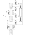
- Composition> 1 is a configuration diagram of an elevator system 101 according to embodiment 1.
- the elevator system 101 includes a people flow control unit 11, a robot 12, an operation control unit 13, and an elevator 14.
- the people flow control unit 11 controls the robot 12 to control the flow of people toward the elevator 14. Specifically, the people flow control unit 11 determines the control content of the robot 12, and transmits control information including the determined control content to the robot 12.
- the robot 12 moves autonomously based on the control information acquired from the people flow control unit 11, and performs people flow control and acquires people flow data.
- People flow data is data that can determine when, where, and how many people are present.
- the robot 12 is equipped with, for example, a camera or a sensor as a configuration for acquiring people flow data. When the robot 12 acquires people flow data, it transmits it to the people flow control unit 11 together with the positional information of the robot 12 at the time the people flow data was acquired.
- the robot 12 is also equipped with a projection device that projects an image onto a floor or a wall as a configuration for performing people flow control.
- the robot 12 may also be equipped with a touch panel, a display, or a speaker as other configuration for performing people flow control.
- the operation control unit 13 controls the operation of an elevator 14 installed in a building such as a building.
- the operation control unit 13 and the elevator 14 exchange information.
- the operation control unit 13 receives operation data of the elevator 14 from the elevator 14.
- the operation data includes operation information of the elevator 14 cage, such as information on the cage's position, speed, door open/closed state, or load.
- the operation control unit 13 determines the operation control content of the elevator 14 based on the operation data, and transmits operation control information including the determined operation control content to the elevator 14.
- the elevator 14 operates based on the operation control information received from the operation control unit 13.
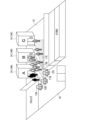
- FIG. 2 shows the flow of people in an elevator hall when the elevator system 101 is not controlling the flow of people.
- Passengers who proceed from the passage 16 to the elevator hall 15 enter the elevator hall 15 and enter the elevators A 14A, B 14B, and C 14C. Get into one of the cages.
- Figure 3 shows the flow of people in an elevator hall when people flow control is performed by elevator system 101.
- Robots 12A, 12B, and 12C are provided in elevator hall 15 or passageway 16.
- Robot 12A displays path 17A to car A 14A in elevator hall 15 on the floor of elevator hall 15 by projection mapping.
- robots 12B and 12C display paths 17A and 17B to car B 14B and car C 14C in elevator hall 15 on the floor of elevator hall 15 by projection mapping.
- paths 17A, 17B, and 17C are set so as not to intersect or overlap with each other.
- the people flow control unit 11 and the operation control unit 13 handle network data.
- network data each location in a building where an elevator 14 is installed is represented by a node, and edges connect the nodes between which people can move.
- Figures 4 to 6 show the allowable network data, which is the network data created by the people flow control unit 11.
- nodes 51, 52, and 53 have values that represent the capacity of the corresponding locations.
- the values of nodes 51, 52, and 53 are V1, V2, and V3, respectively.
- FIG. 7 is a flowchart showing the operation of the people flow control unit 11. The operation of the people flow control unit 11 will be described below with reference to the flow in FIG. 7.
- the people flow control unit 11 receives people flow data and position information from the robot 12.
- the people flow data received here has been acquired by the robot 12 using a camera or sensor, etc.
- the position information is the coordinates at the time when the robot 12 acquired the people flow data.
- step S107 the people flow control unit 11 transmits control data including the details of the people flow control set in step S106 to the robot 12. This ends the processing of the people flow control unit 11.
- step S202 the operation control unit 13 calculates the number of passengers getting on and off the elevator 14 at each floor based on the operation data.
- the operation control unit 13 determines the floor on which the car is located from the car position, and calculates the number of passengers getting on and off by dividing the change in car load when the car is stopped and the door is open by the load per passenger.
- An increase in car load is related to boarding, and a decrease in car load is related to disembarking.
- step S203 the operation control unit 13 transmits the number of people getting on and off at each floor calculated in step S202 to the people flow control unit 11.
- step S205 the operation control unit 13 obtains the number of passengers required for the elevator 14 to transport on each floor from the real network data. Specifically, the operation control unit 13 determines the number of passengers present in the elevator hall 15 in the real network data as the number of passengers required for the elevator 14 to transport. Alternatively, the operation control unit 13 may determine the number of passengers moving from the passage 16 to the elevator hall 15 in the real network data as the number of passengers required for the elevator 14 to transport.
- step S207 the operation control unit 13 sends a people flow control request to the people flow control unit 11. This ends the processing of the operation control unit 13.
- the elevator system 101 includes the robot 12 that moves autonomously in a building in which an elevator 14 having multiple cars is installed and measures people flow data around itself with a measuring device mounted on the robot 12, and the people flow control unit 11 that causes the robot 12 to perform people flow control, which is control of the flow of people heading toward the elevator 14, based on the people flow data measured by the robot 12 and the operation data of the elevator 14. Therefore, even in crowded conditions, the robot 12 can safely and smoothly guide passengers to the cars they will board. As a result, a decrease in the transportation efficiency of the elevator 14 is suppressed.
- the robot 12 performs people flow control to utilize the transportation capacity of the elevator 14, thereby reducing congestion in the elevator hall 15.
- the elevator hall 15 will become congested. When it becomes crowded, passengers' movement space and field of vision become narrower, making it difficult for people flow control to be effective and creating the risk of collisions due to the crowding.
- the elevator system 102 restricts passengers from moving into the elevator hall 15 when the elevator hall 15 is crowded and there are more passengers than the elevator 14 can transport. At this time, the robot 12 moves to the vicinity of the entrance to the elevator hall 15 and urges passengers not to move into the elevator hall 15 by audio guidance or by physically blocking the entrance.
- the people flow control unit 11 creates evaluation network data, which is network data for evaluating the congestion degree of a node, from the allowable network data and actual network data described in embodiment 1.
- FIG 9 shows the evaluation network data.
- each node 51, 52, 53 has a value that represents the congestion level.
- the congestion level is calculated by dividing the number of people present at each node in the actual network data by the allowable number of people at each node in the allowable network data.
- node 51 in the passage 16 has a congestion level of 30%
- node 52 in the elevator hall 15 has a congestion level of 90%
- node 53 in the elevator 14 has a congestion level of 60%.
- the people flow control unit 11 classifies nodes whose congestion level is equal to or greater than a predetermined first threshold as congested nodes, and other nodes as non-congested nodes. If a congestion level of 80% is set as the threshold for a congested node, node 52 in the elevator hall 15 is classified as a congested node, and the other nodes 51 and 3 are classified as non-congested nodes.
- the people flow control unit 11 places the robot 12 between the passage 16 and the elevator hall 15 in order to limit the amount of people flowing into node 52, which is a crowded node, the elevator hall 15. This state is shown in Figure 10.
- Figure 11 shows the congestion level of each node after people flow control by the robot 12. As shown in Figure 11, the congestion level of the passageway 16 increases from 30% to 45%, while the congestion level of the elevator hall 15 decreases from 90% to 60%, easing congestion in the elevator hall 15. Note that although the congestion level of the passageway 16 is now 45%, this is not high enough to be determined as a congested node.
- FIG. 12 is a flowchart showing the operation of the people flow control unit 11 in the elevator system 102. Below, the operation of the people flow control unit 11 in the elevator system 102 will be explained with reference to FIG. 12.
- step S301 the people flow control unit 11 receives people flow data and position information from the robot 12. This step is similar to step S101 in FIG. 7.
- step S302 the people flow control unit 11 obtains the number of people getting on and off the elevator 14 at each floor from the operation control unit 13. This step is the same as step S102 in FIG. 7.
- step S303 the people flow control unit 11 creates real network data based on the data acquired in steps S301 and S302. This step is the same as step S103 in FIG. 7.
- step S304 the people flow control unit 11 creates evaluation network data based on the actual network data and the allowable network data.
- the people flow control unit 11 determines whether or not there is a congested node in the evaluation network data.
- a node whose congestion level is equal to or greater than a predetermined value is a congested node.
- the congestion level threshold for determining whether a node is congested is derived, for example, based on the area of the elevator hall 15 and a personal space for maintaining safety or comfort. If there is no congested node, the processing of the people flow control unit 11 ends.
- step S306 the people flow control unit 11 judges whether the adjacent node connected to the inflow edge to the congested node is an empty node. Whether a node is empty or not is judged, for example, according to the following calculation.
- the judgement target node For a node to be judged as to whether it is an empty node or not (hereinafter referred to as the judgement target node), the allowable number of people is V and the number of people present is v. Then, the number of passengers flowing into the judgement target node per unit time is e_in, and the number of passengers flowing out from the judgement target node to a congested node per unit time is e_out. The number of passengers flowing out to the congested node per unit time that is expected to decrease due to people flow control is e_out'.
- the duration of people flow control is T
- the number of people present at the node being evaluated increases by (e_in - e_out') x T. If the difference (V - v) between the allowable number of people at the node being evaluated and the number of people present is equal to or greater than the increase in the number of people present due to people flow control (e_in - e_out') x T, the node being evaluated is determined to be an empty node.
- the people flow control unit 11 may group multiple adjacent nodes together and determine whether the multiple nodes are vacant or not. In this case, the determination is made using the combined allowable number of people for the multiple nodes, the number of people present, the number of passengers entering when the multiple nodes are considered as one node, and the number of passengers leaving the crowded node.
- the processing of the people flow control unit 11 ends.
- the people flow control unit 11 sets people flow control to suppress inflow from the empty node to the crowded node in step S307. For example, if the elevator hall 15 is a crowded node and the passageway 16 is an empty node, the people flow control unit 11 moves the robot 12 from the passageway 16 to near the entrance to the elevator hall 15, and urges the robot 12 not to move into the elevator hall 15 with audio guidance or physically blocks the entrance to the elevator hall 15, etc., as the control content for the robot 12.
- step S308 the people flow control unit 11 transmits control data including the control contents set in step S307 to the robot 12.
- the people flow control unit 11 judges a node whose congestion level is equal to or higher than a predetermined threshold to be a congested node.
- the people flow control includes restricting the inflow of people into the congested node.
- Composition> 13 is a configuration diagram of an elevator system 103 according to embodiment 3.
- the elevator system 103 includes a hall call registration device 18 in addition to the configuration of the elevator system 101 according to embodiment 1.
- the people flow control unit 11 causes the robot 12 to move to a specified position and acquire people flow data. For example, by acquiring people flow data on a route leading to an elevator hall 15, it is possible to predict congestion in the elevator hall 15. In addition, if the number of hall call registration devices 18 is variable, it is possible to set the number of hall call registration devices 18 that meets demand by acquiring people flow data in front of the hall call registration devices 18.
- the robot 12 moves and acquires people flow data according to the control of the people flow control unit 11.
- the people flow control unit 11 generates control data for the robot 12 according to the people flow data from the previous time and the data acquired from the operation control unit 13.
- the operation control unit 13 manages the hall call registration devices 18 in addition to the elevators 14.
- the number of hall call registration devices 18 installed is variable under the control of the operation control unit 13.
- the number of hall call registration devices 18 installed is changed by the hall call registration devices 18 moving independently or by moving the hall call registration devices 18 manually.
- the hall call registration devices 18 are configured with digital signage such as advertising panels, the number of hall call registration devices 18 installed may be changed by switching the display content of the digital signage.
- the platform call registration device 18 and the elevator 14 communicate with each other.
- the platform call registration device 18 transmits call registration data to the elevator 14, and the call is registered in the elevator 14.
- the elevator 14 determines the boarding car for the call and transmits the boarding car data to the platform call registration device 18.
- the platform call registration device 18 guides the passenger to the boarding car.
- the platform call registration device 18 transmits an operation log to the elevator 14, and the elevator 14 has the operation log of the platform call registration device 18.
- Fig. 14 is a flowchart showing the operation of the people flow control unit 11 in embodiment 3. The operation of the people flow control unit 11 will be described below along the flow of Fig. 14.
- step S401 the people flow control unit 11 acquires people flow data and position information from the robot 12.
- the people flow data and position information received here do not relate to a position specified by the people flow control unit 11.
- step S402 the people flow control unit 11 acquires operation data from the operation control unit 13.
- This operation data includes the position of the hall call registration device 18 and the log data of the hall call registration device 18 in addition to the operation log of the elevator 14.
- the people flow control unit 11 determines, based on the operation data, whether or not there is a designated location from which people flow data should be obtained. For example, if the people flow control unit 11 determines, based on the previous actual network data and operation control, that the elevator hall 15 is quiet at the current time, it determines to move the robot 12 to a designated location, for example, the passage 16 leading to the elevator hall 15, in preparation for future congestion, and to obtain people flow data in the passage 16. In other words, the people flow control unit 11 determines the passage 16 as the designated location.
- the people flow control unit 11 determines that congestion is occurring in front of the platform call registration device 18 and determines the platform call registration device 18 to be the designated position. For example, based on the operation data acquired from the operation control unit 13, the people flow control unit 11 determines that congestion is occurring in front of the platform call registration device 18 when the period during which the usage interval of the platform call registration device 18 is below a predetermined threshold continues for a certain period of time or longer.
- step S403 If no position is specified in step S403, the processing of the people flow control unit 11 proceeds to step S411.
- step S405 the people flow control unit 11 transmits control data including the control contents set in step S404 to the robot 12.
- step S406 the people flow control unit 11 receives people flow data and position information at the specified position from the robot 12.
- Steps S407 to S412 after step S406 are similar to steps S102 to S106 in FIG. 7, so their explanation is omitted.
- FIG. 15 is a flowchart showing the operation of the operation control unit 13 in embodiment 3. The operation of the operation control unit 13 will be explained below according to the flow of FIG. 15.
- step S501 the operation control unit 13 acquires operation data from the elevator 14.
- This operation data includes the operation log of the elevator 14, as well as the position of the hall call registration device 18 and the log of the hall call registration device 18.
- step S502 the operation control unit 13 transmits operation data to the people flow control unit 11.
- the subsequent steps S503 to S505 are similar to steps S202 to S204 in FIG. 8, and therefore will not be described.
- step S506 the operation control unit 13 sets the contents of operation control based on the actual network data acquired in step S505. For example, if there are many people flowing into the node connected to the elevator hall 15, the operation control unit 13 determines that the elevator hall 15 will be crowded in the future, and sets operation control to improve transportation efficiency from the elevator hall 15 in advance.
- the operation control unit 13 increases the number of platform call registration devices 18 so that the waiting time from lining up to operating the platform call registration device 18 is less than a predetermined time.
- step S507 the operation control unit 13 transmits operation control data including the operation control details set in step S506 to the elevator 14 and the hall call registration device 18.
- the people flow control unit 11 determines a designated position where the robot 12 should next measure people flow data based on people flow data measured by the robot 12. Then, the robot 12 measures the people flow data at the designated position. This allows the people flow control unit 11 to accurately grasp the people flow in the building and control the people flow.
- Composition> 16 is a configuration diagram of an elevator system 104 according to embodiment 4.
- the elevator system 104 is obtained by adding a learning unit 19 to the elevator system 103 according to embodiment 3.
- the elevator system 104 may be obtained by adding the learning unit 19 to the elevator system 101 according to embodiment 1.
- the learning unit 19 exchanges data with the people flow control unit 11.
- the learning unit 19 receives real network data from the people flow control unit 11 and accumulates the received real network data.
- the learning unit 19 also uses past real network data to calculate a prediction model for predicting future real network data.
- the learning unit 19 may calculate the prediction model during times when there are no passengers, such as at night.
- the learning unit 19 may also generate a prediction model for each day of the week or each time period.
- the learning unit 19 may also calculate the prediction model using machine learning such as deep learning.
- the learning unit 19 transmits the calculated prediction model to the people flow control unit 11.
- the people flow control unit 11 creates real network data based on the people flow data received from the robot 12. In addition, the people flow control unit 11 transmits real network data to the learning unit 19 every time it creates real network data.
- the people flow control unit 11 acquires a prediction model from the learning unit 19.
- the people flow control unit 11 generates future actual network data based on the prediction model and the most recent actual network data.
- the people flow control unit 11 sets the control content of the robot 12 based on the future actual network data, and transmits control data including the control content to the robot 12.
- Other operations of the people flow control unit 11 are the same as those in the first embodiment.
- the operation control unit 13 sets operation control contents based on the future actual network data received from the people flow control unit 11, and transmits operation control data including the operation control contents to the elevator 14 or the hall call registration device 18. Other operations of the operation control unit 13 are the same as those in the first embodiment.
- Operation> 17 is a flowchart showing the operation of the people flow control unit 11 according to embodiment 4. The operation of the people flow control unit 11 will be described below with reference to the flowchart in FIG.
- step S601 the people flow control unit 11 acquires a prediction model from the learning unit 19.
- the timing for acquiring the prediction model is, for example, early in the morning when the learning unit 19 has finished calculating the prediction model.
- Steps S602 to S604 following step S601 are similar to steps S101 to S103 in FIG. 7.
- step S604 the people flow control unit 11 transmits the actual network data to the learning unit 19.
- step S606 the people flow control unit 11 creates future actual network data based on the prediction model and the most recent actual network data.
- the people flow control unit 11 inputs the most recent actual network data created in step S604 into the prediction model acquired in step S601, and acquires future actual network data as the output of the prediction model.
- step S607 the people flow control unit 11 sets the control content for the robot 12 based on the future real network data created in step S606. For example, if there is a congested node in the future real network data, the people flow control unit 11 sets the control content for the robot 12 to move to the congested node. Alternatively, as described in steps S104 to S106 of FIG. 7, the people flow control unit 11 may send the future real network data to the operation control unit 13 and set the people flow control content in response to a people flow control request received from the operation control unit 13.
- step S608 the people flow control unit 11 transmits control data including the control content set in step S607 to the robot 12.
- FIG. 18 is a flowchart showing the operation of the operation control unit 13 according to embodiment 4. The operation of the operation control unit 13 will be explained below according to the flow of FIG. 18.
- Steps S701 to S703 are similar to steps S201 to S203 in FIG. 8.
- step S703 the operation control unit 13 obtains future actual network data from the people flow control unit 11.
- step S705 the operation control unit 13 sets the operation control content based on the future actual network data. For example, if the number of people present at the node in the elevator hall 15 is large in the future actual network data, the operation control unit 13 changes the setting to operation control content that has the number of people to be transported required for that number of people. In addition, if the number of people present at the node of the hall call registration device 18 is large, the operation control unit 13 sets as operation control content the change in the number of hall call registration devices 18 so that the waiting time for that number of people is below a certain level.
- step S706 the operation control unit 13 transmits control data including operation control details to the elevator 14 or the hall call registration device 18. This ends the processing of the operation control unit 13.
- FIG. 19 is a flowchart showing the operation of the learning unit 19 according to embodiment 4. The operation of the learning unit 19 will be explained below according to the flow of FIG. 19.
- step S801 the learning unit 19 continuously receives and accumulates the actual network data created by the people flow control unit 11.
- step S802 the learning unit 19 determines whether or not it is necessary to calculate a prediction model. For example, the learning unit 19 determines whether the current time is a nighttime period, and if so, determines that a prediction model should be calculated. Note that the calculation time for the prediction model is not limited to nighttime, and may be any time period in which sufficient computing resources are available.
- step S802 If it is determined in step S802 that a predictive model is not to be calculated, the processing of the learning unit 19 ends.
- step S802 If it is determined in step S802 that a prediction model is to be calculated, the learning unit 19 calculates a prediction model in step S803. For example, the learning unit 19 uses the accumulated real network data as input and creates a prediction model for predicting future real network data by deep learning.
- step S804 the learning unit 19 transmits the calculated prediction model to the people flow control unit 11.
- the people flow control unit 11 creates future actual network data based on a predictive model, so people flow control and operation control can be performed in advance to prevent congestion in the elevator hall 15, etc.
- the people flow control unit 11 predicts future actual network data from actual network data created based on people flow data measured by the robot 12, and determines the content of people flow control based on the future actual network data. This makes it possible to predict future congestion conditions and quickly control people flow.
- FIG. 20 is a configuration diagram of the facility plan creation device 105 according to the fifth embodiment.
- the facility plan creation device 105 includes a simulation unit 30 and a facility design unit 35.
- the simulation unit 30 includes a people flow control unit 31, a virtual robot 32, an operation control unit 33, and a virtual elevator 34, and is a virtual configuration of the elevator system 101 according to the first embodiment using an information terminal such as a personal computer.
- the people flow control unit 31 and the operation control unit 33 have the same functions as the people flow control unit 11 and the operation control unit 13 according to the first embodiment.
- the virtual robot 32 is a virtual configuration of the robot 12 according to the first embodiment using an information terminal.
- the virtual elevator 34 is a virtual configuration of the elevator 14 according to the first embodiment using an information terminal.
- the simulation unit 30 may be a virtual configuration of any of the elevator systems 102-104 according to the second to fourth embodiments using an information terminal such as a personal computer.
- the equipment design unit 35 is composed of an information terminal such as a personal computer, and sets the specifications of the elevator system 101.
- the specifications of the elevator system 101 include elevator specifications, which are the specifications of the elevator 14, building specifications, which are the specifications of the building in which the elevator 14 is installed, robot specifications, which are the specifications of the robot 12, and design standard specifications.
- the building specifications include the number of floors, floor height, layout of each floor, and floor use.
- the elevator specifications include the arrangement, number, and functions of the elevators 14.
- the design standard specifications include the required transport efficiency and budget.
- the robot specifications include the number and functions of the robots 12.
- the equipment design unit 35 determines the building specifications and design standard specifications based on information manually entered by the user of the information terminal.
- the simulation unit 30 receives specification data that defines the specifications of the elevator system 101 and passenger data from the equipment design unit 35.
- the passenger data is, for example, the time-series network data described in the first embodiment, and shows the number of people present at each node in the building and the number of people moving between the nodes in a time series.
- the simulation unit 30 performs a simulation based on the data received from the equipment design unit 35, and transmits the simulation results to the equipment design unit 35.
- the simulation results include the time-series network data for the simulation period.
- the equipment design unit 35 judges whether the simulation results received from the simulation unit 30 satisfy the design standard specifications.
- the judgment criterion is, for example, whether the average passenger waiting time obtained by statistical processing of the simulation results is equal to or less than the average waiting time defined in the design standard specifications. If the simulation results do not satisfy the design standard specifications, the equipment design unit 35 changes the elevator specifications and robot specifications and sends these specifications to the simulation unit 30.
- the simulation unit 30 performs a simulation using the changed elevator specifications and robot specifications and sends the simulation results to the equipment design unit 35.
- the equipment design unit 35 repeats the change of the elevator specifications and robot specifications until the simulation results satisfy the design standard specifications. In this way, the equipment design unit 35 changes the elevator specifications and robot specifications for the building specifications so that they satisfy the design standard specifications.
- the equipment design unit 35 displays the elevator specifications, robot specifications, and simulation results on the output screen of an information terminal, etc.
- Fig. 21 is a flowchart showing the operation of the facility design unit 35 according to embodiment 5. The operation of the facility design unit 35 will be described below with reference to the flow of Fig. 21.
- the facility design unit 35 sets the building specifications.
- the facility design unit 35 accepts input from a user of the information terminal and sets the building specifications based on the input information.
- the building specifications may be represented by BIM data or CAD data.
- step S902 the equipment design unit 35 sets the design standard specifications.
- the equipment design unit 35 accepts input from the user of the information terminal and sets the design standard specifications based on the input information.
- the equipment design unit 35 determines the elevator specifications for the building specifications and the design standard specifications.
- the equipment design unit 35 sets the elevator specifications based on the results of the previous simulation. For example, if the average passenger waiting time in the results of the previous simulation is poor and the average passenger waiting time in the results of the simulation before last is too good, the equipment design unit 35 increases the number of cars in the elevator specifications to a range less than the number of cars in the elevator specifications before last.
- step S904 the equipment design unit 35 sets the robot specifications for the building specifications, the design standard specifications, and the elevator specifications.
- the equipment design unit 35 sets the robot specifications based on the results of the previous simulation. For example, if the passenger waiting time in the results of the previous simulation is poor and the average passenger waiting time in the results of the simulation before last is too good, the equipment design unit 35 increases the number of robots in the robot specifications to a level less than the number of robots in the robot specifications before last.
- step S905 the equipment design unit 35 transmits each of the specifications set in steps S901 to S904 to the simulation unit 30. Then, the simulation unit 30 simulates the operation of the elevator system 101 based on the specifications received from the equipment design unit 35.
- step S906 the facility design unit 35 receives the simulation results from the simulation unit 30.
- step S907 the equipment design unit 35 judges whether the simulation result satisfies the design standard specifications. If the simulation result is close to the conditions set in the design standard specifications, the equipment design unit 35 judges that the simulation result satisfies the design standard.
- the equipment design unit 35 may focus on the average waiting time of passengers in the elevator hall 15 and judge whether the simulation result satisfies the design standard specifications. For example, if the average waiting time is set to 30 seconds or less in the design standard specifications, but the number of elevators is 7 and the average waiting time in the simulation result is 10 seconds, the elevator specifications and robot specifications are excessive compared to the design standard specifications. Therefore, the equipment design unit 35 may change the elevator specifications so that the average waiting time becomes worse.
- the equipment design unit 35 judges that the equipment standard specifications are satisfied when the number of elevators is 5.
- the equipment design unit 35 If the simulation results do not satisfy the design criteria in step S907, the equipment design unit 35 returns to step S903. That is, the equipment design unit 35 modifies the equipment design data based on the comparison result between the simulation results and the design criteria specifications required for the elevator system, and inputs the modified equipment design data to the simulation unit 30.
- the equipment design unit 35 outputs the simulation results that satisfy the design criteria specifications to the information terminal screen in step S908.
- the facility plan creation device 105 includes a simulation unit 30 that simulates the processing of the elevator system, and a facility design unit 35 that determines the specifications of the elevator system.
- the elevator system is any one of the elevator systems according to the first to fourth embodiments.
- the facility design unit 35 inputs facility design data including passenger specifications, elevator specifications, and robot specifications generated in the simulation to the simulation unit 30, and the simulation unit 30 simulates the processing of the elevator system based on the facility design data.
- the people flow control unit 11, the operation control unit 13, the virtual robot 32, and the virtual elevator 34 in the above-mentioned elevator systems 101-104 and facility plan creation device 105 are realized by a processing circuit 81 shown in Fig. 22. That is, the processing circuit 81 includes the people flow control unit 11, the operation control unit 13, the virtual robot 32, and the virtual elevator 34 (hereinafter referred to as "people flow control unit 11, etc.”).
- the processing circuit 81 may be implemented with dedicated hardware or a processor that executes a program stored in a memory.
- the processor may be, for example, a central processing unit, a processing unit, an arithmetic unit, a microprocessor, a microcomputer, a DSP (Digital Signal Processor), or the like.
- the processing circuit 81 When the processing circuit 81 is dedicated hardware, the processing circuit 81 corresponds to, for example, a single circuit, a composite circuit, a programmed processor, a parallel programmed processor, an ASIC (Application Specific Integrated Circuit), an FPGA (Field-Programmable Gate Array), or a combination of these.
- Each function of the people flow control unit 11 and other units may be realized by multiple processing circuits 81, or the functions of each unit may be combined and realized by a single processing circuit.
- the processing circuit 81 When the processing circuit 81 is a processor, the functions of the people flow control unit 11, etc. are realized by a combination of software, etc. (software, firmware, or software and firmware).
- the software, etc. is written as a program and stored in memory.
- the processor 82 applied to the processing circuit 81 realizes the functions of each unit by reading and executing a program stored in the memory 83. That is, the elevator system 101-104 and the facility planning creation device 105 are provided with a memory 83 for storing a program which, when executed by the processing circuit 81, results in the execution of each function of the elevator system 101-104 and the facility planning creation device 105.
- the above describes a configuration in which the functions of the people flow control unit 11, etc. are realized either by hardware or software, etc. However, this is not limited to the above, and a configuration in which part of the people flow control unit 11, etc. is realized by dedicated hardware and another part is realized by software, etc.
- the functions of the people flow control unit 11 can be realized by a processing circuit as dedicated hardware, and the other functions can be realized by the processing circuit 81 as the processor 82 reading and executing a program stored in the memory 83.
- the processing circuit can realize each of the above-mentioned functions by hardware, software, etc., or a combination of these.
Landscapes
- Engineering & Computer Science (AREA)
- Automation & Control Theory (AREA)
- Elevator Control (AREA)
- Indicating And Signalling Devices For Elevators (AREA)
Priority Applications (2)
| Application Number | Priority Date | Filing Date | Title |
|---|---|---|---|
| JP2024562440A JPWO2024121934A1 (https=) | 2022-12-06 | 2022-12-06 | |
| PCT/JP2022/044901 WO2024121934A1 (ja) | 2022-12-06 | 2022-12-06 | エレベータシステムおよび設備計画作成装置 |
Applications Claiming Priority (1)
| Application Number | Priority Date | Filing Date | Title |
|---|---|---|---|
| PCT/JP2022/044901 WO2024121934A1 (ja) | 2022-12-06 | 2022-12-06 | エレベータシステムおよび設備計画作成装置 |
Publications (1)
| Publication Number | Publication Date |
|---|---|
| WO2024121934A1 true WO2024121934A1 (ja) | 2024-06-13 |
Family
ID=91378814
Family Applications (1)
| Application Number | Title | Priority Date | Filing Date |
|---|---|---|---|
| PCT/JP2022/044901 Ceased WO2024121934A1 (ja) | 2022-12-06 | 2022-12-06 | エレベータシステムおよび設備計画作成装置 |
Country Status (2)
| Country | Link |
|---|---|
| JP (1) | JPWO2024121934A1 (https=) |
| WO (1) | WO2024121934A1 (https=) |
Citations (4)
| Publication number | Priority date | Publication date | Assignee | Title |
|---|---|---|---|---|
| JP2007072682A (ja) * | 2005-09-06 | 2007-03-22 | Toshiba Elevator Co Ltd | Cadシステム |
| WO2017199532A1 (ja) * | 2016-05-18 | 2017-11-23 | 株式会社日立製作所 | シミュレーション装置、方法、及びコンピュータプログラム |
| JP2019099327A (ja) * | 2017-12-01 | 2019-06-24 | 株式会社日立製作所 | エレベーターシステム |
| WO2021152771A1 (ja) * | 2020-01-30 | 2021-08-05 | 三菱電機株式会社 | 昇降機案内装置及び昇降機案内方法 |
-
2022
- 2022-12-06 WO PCT/JP2022/044901 patent/WO2024121934A1/ja not_active Ceased
- 2022-12-06 JP JP2024562440A patent/JPWO2024121934A1/ja active Pending
Patent Citations (4)
| Publication number | Priority date | Publication date | Assignee | Title |
|---|---|---|---|---|
| JP2007072682A (ja) * | 2005-09-06 | 2007-03-22 | Toshiba Elevator Co Ltd | Cadシステム |
| WO2017199532A1 (ja) * | 2016-05-18 | 2017-11-23 | 株式会社日立製作所 | シミュレーション装置、方法、及びコンピュータプログラム |
| JP2019099327A (ja) * | 2017-12-01 | 2019-06-24 | 株式会社日立製作所 | エレベーターシステム |
| WO2021152771A1 (ja) * | 2020-01-30 | 2021-08-05 | 三菱電機株式会社 | 昇降機案内装置及び昇降機案内方法 |
Also Published As
| Publication number | Publication date |
|---|---|
| JPWO2024121934A1 (https=) | 2024-06-13 |
Similar Documents
| Publication | Publication Date | Title |
|---|---|---|
| EP3705439B1 (en) | Building interior human flow prediction system and prediction method | |
| JP6585285B2 (ja) | 人流評価システム、人流制御の検討方法 | |
| CN101477580A (zh) | 人流运算装置 | |
| CN111201192B (zh) | 建筑物内交通预测系统、建筑物内交通预测系统中的电梯门厅布局的生成方法 | |
| JP7277257B2 (ja) | 移動需要推定システム及び人流推定システム | |
| JP7273601B2 (ja) | 混雑解析装置及び混雑解析方法 | |
| JP2016035665A (ja) | 入出場ゲート制御システム及び入出場制御方法 | |
| Ruokokoski et al. | Assignment formulation for the Elevator Dispatching Problem with destination control and its performance analysis | |
| WO2023061959A1 (en) | Control of a complex environment | |
| JP7461231B2 (ja) | 混雑推定システムおよび混雑推定方法 | |
| JPWO2017056528A1 (ja) | 混雑予測システムおよび混雑予測方法 | |
| CN115917549A (zh) | 设备布局异常判定装置及设备布局异常判定方法 | |
| WO2024121934A1 (ja) | エレベータシステムおよび設備計画作成装置 | |
| Cortés et al. | Design and analysis of a tool for planning and simulating dynamic vertical transport | |
| JP2020169083A (ja) | 昇降機の運行状態表示装置、運行状態表示システム及び運行状態表示方法 | |
| Wang et al. | Boarding time estimation using the passenger density distribution on the bus | |
| KR102783278B1 (ko) | 멀티모드 수송 네트워크를 통제하기 위한 방법 | |
| JP2000318938A (ja) | エレベータ群管理簡易シミュレータならびにエレベータ群管理装置 | |
| JP3881412B2 (ja) | エレベータ群割当て管理制御装置、エレベータ群割当て管理制御方法、エレベータ群割当て管理制御プログラムを記録した媒体。 | |
| JP6776174B2 (ja) | エレベーター利用者移動予測方法およびエレベーター利用者移動予測装置 | |
| Basagoiti et al. | Passenger flow pattern learning based on trip counting in lift systems combined with real-time information | |
| EP4216116A1 (en) | In-building traffic flow setting device and in-building traffic flow setting method | |
| JP2728396B2 (ja) | エレベーター制御装置 | |
| JP7310967B1 (ja) | エレベーターシステム及び評価システム | |
| KR101943610B1 (ko) | 보행자 유형별 이동경로 산출 장치 및 방법 |
Legal Events
| Date | Code | Title | Description |
|---|---|---|---|
| 121 | Ep: the epo has been informed by wipo that ep was designated in this application |
Ref document number: 22967787 Country of ref document: EP Kind code of ref document: A1 |
|
| WWE | Wipo information: entry into national phase |
Ref document number: 2024562440 Country of ref document: JP |
|
| NENP | Non-entry into the national phase |
Ref country code: DE |
|
| 122 | Ep: pct application non-entry in european phase |
Ref document number: 22967787 Country of ref document: EP Kind code of ref document: A1 |