WO2024116710A1 - バルーンカテーテル及びバルーンカテーテルの製造方法 - Google Patents
バルーンカテーテル及びバルーンカテーテルの製造方法 Download PDFInfo
- Publication number
- WO2024116710A1 WO2024116710A1 PCT/JP2023/039483 JP2023039483W WO2024116710A1 WO 2024116710 A1 WO2024116710 A1 WO 2024116710A1 JP 2023039483 W JP2023039483 W JP 2023039483W WO 2024116710 A1 WO2024116710 A1 WO 2024116710A1
- Authority
- WO
- WIPO (PCT)
- Prior art keywords
- balloon
- groove
- protrusion
- parison
- linear protrusion
- Prior art date
- Legal status (The legal status is an assumption and is not a legal conclusion. Google has not performed a legal analysis and makes no representation as to the accuracy of the status listed.)
- Ceased
Links
Images







Classifications
-
- A—HUMAN NECESSITIES
- A61—MEDICAL OR VETERINARY SCIENCE; HYGIENE
- A61M—DEVICES FOR INTRODUCING MEDIA INTO, OR ONTO, THE BODY; DEVICES FOR TRANSDUCING BODY MEDIA OR FOR TAKING MEDIA FROM THE BODY; DEVICES FOR PRODUCING OR ENDING SLEEP OR STUPOR
- A61M25/00—Catheters; Hollow probes
- A61M25/10—Balloon catheters
-
- A—HUMAN NECESSITIES
- A61—MEDICAL OR VETERINARY SCIENCE; HYGIENE
- A61M—DEVICES FOR INTRODUCING MEDIA INTO, OR ONTO, THE BODY; DEVICES FOR TRANSDUCING BODY MEDIA OR FOR TAKING MEDIA FROM THE BODY; DEVICES FOR PRODUCING OR ENDING SLEEP OR STUPOR
- A61M25/00—Catheters; Hollow probes
- A61M25/10—Balloon catheters
- A61M25/1002—Balloon catheters characterised by balloon shape
-
- A—HUMAN NECESSITIES
- A61—MEDICAL OR VETERINARY SCIENCE; HYGIENE
- A61M—DEVICES FOR INTRODUCING MEDIA INTO, OR ONTO, THE BODY; DEVICES FOR TRANSDUCING BODY MEDIA OR FOR TAKING MEDIA FROM THE BODY; DEVICES FOR PRODUCING OR ENDING SLEEP OR STUPOR
- A61M25/00—Catheters; Hollow probes
- A61M25/10—Balloon catheters
- A61M25/1027—Making of balloon catheters
-
- A—HUMAN NECESSITIES
- A61—MEDICAL OR VETERINARY SCIENCE; HYGIENE
- A61M—DEVICES FOR INTRODUCING MEDIA INTO, OR ONTO, THE BODY; DEVICES FOR TRANSDUCING BODY MEDIA OR FOR TAKING MEDIA FROM THE BODY; DEVICES FOR PRODUCING OR ENDING SLEEP OR STUPOR
- A61M25/00—Catheters; Hollow probes
- A61M25/10—Balloon catheters
- A61M25/1027—Making of balloon catheters
- A61M25/1029—Production methods of the balloon members, e.g. blow-moulding, extruding, deposition or by wrapping a plurality of layers of balloon material around a mandril
-
- A—HUMAN NECESSITIES
- A61—MEDICAL OR VETERINARY SCIENCE; HYGIENE
- A61M—DEVICES FOR INTRODUCING MEDIA INTO, OR ONTO, THE BODY; DEVICES FOR TRANSDUCING BODY MEDIA OR FOR TAKING MEDIA FROM THE BODY; DEVICES FOR PRODUCING OR ENDING SLEEP OR STUPOR
- A61M25/00—Catheters; Hollow probes
- A61M25/10—Balloon catheters
- A61M25/1002—Balloon catheters characterised by balloon shape
- A61M2025/1004—Balloons with folds, e.g. folded or multifolded
-
- A—HUMAN NECESSITIES
- A61—MEDICAL OR VETERINARY SCIENCE; HYGIENE
- A61M—DEVICES FOR INTRODUCING MEDIA INTO, OR ONTO, THE BODY; DEVICES FOR TRANSDUCING BODY MEDIA OR FOR TAKING MEDIA FROM THE BODY; DEVICES FOR PRODUCING OR ENDING SLEEP OR STUPOR
- A61M25/00—Catheters; Hollow probes
- A61M25/10—Balloon catheters
- A61M25/1027—Making of balloon catheters
- A61M25/1029—Production methods of the balloon members, e.g. blow-moulding, extruding, deposition or by wrapping a plurality of layers of balloon material around a mandril
- A61M2025/1031—Surface processing of balloon members, e.g. coating or deposition; Mounting additional parts onto the balloon member's surface
-
- A—HUMAN NECESSITIES
- A61—MEDICAL OR VETERINARY SCIENCE; HYGIENE
- A61M—DEVICES FOR INTRODUCING MEDIA INTO, OR ONTO, THE BODY; DEVICES FOR TRANSDUCING BODY MEDIA OR FOR TAKING MEDIA FROM THE BODY; DEVICES FOR PRODUCING OR ENDING SLEEP OR STUPOR
- A61M25/00—Catheters; Hollow probes
- A61M25/10—Balloon catheters
- A61M2025/1043—Balloon catheters with special features or adapted for special applications
-
- A—HUMAN NECESSITIES
- A61—MEDICAL OR VETERINARY SCIENCE; HYGIENE
- A61M—DEVICES FOR INTRODUCING MEDIA INTO, OR ONTO, THE BODY; DEVICES FOR TRANSDUCING BODY MEDIA OR FOR TAKING MEDIA FROM THE BODY; DEVICES FOR PRODUCING OR ENDING SLEEP OR STUPOR
- A61M25/00—Catheters; Hollow probes
- A61M25/10—Balloon catheters
- A61M2025/1043—Balloon catheters with special features or adapted for special applications
- A61M2025/1086—Balloon catheters with special features or adapted for special applications having a special balloon surface topography, e.g. pores, protuberances, spikes or grooves
-
- A—HUMAN NECESSITIES
- A61—MEDICAL OR VETERINARY SCIENCE; HYGIENE
- A61M—DEVICES FOR INTRODUCING MEDIA INTO, OR ONTO, THE BODY; DEVICES FOR TRANSDUCING BODY MEDIA OR FOR TAKING MEDIA FROM THE BODY; DEVICES FOR PRODUCING OR ENDING SLEEP OR STUPOR
- A61M2207/00—Methods of manufacture, assembly or production
- A61M2207/10—Device therefor
Definitions
- the present disclosure relates to a balloon catheter and a method for manufacturing a balloon catheter.
- Balloon catheters have traditionally been used in treatments such as PTA (percutaneous transluminal angioplasty) and PTCA (percutaneous transluminal coronary angioplasty).
- a balloon catheter has an expandable and contractable balloon at its tip. With a balloon catheter, the balloon is introduced in a contracted state to a location narrowed or blocked by a lesion or the like that has occurred in a blood vessel, and then the balloon is inflated to expand the location.
- the balloon also has a cylindrical straight tube section that is at its largest diameter when inflated, and a pair of tapered sections that are located at the base end and tip end of the straight tube section and that decrease in diameter toward the side away from the straight tube section.
- Some balloon catheters are provided with linear protrusions that protrude from the surface of the straight tube section of the balloon and extend linearly along the surface of the straight tube section (see, for example, Patent Document 1).
- the linear protrusions can be caused to bite into the lesion, making an incision in the lesion. This makes it easier to expand the lesion using the incision as a trigger.
- the present disclosure has been made in consideration of the above circumstances, and has as its main objective the provision of a balloon catheter and a method for manufacturing a balloon catheter that can suppress a decrease in passability when the balloon is introduced into a tube, while suppressing the balloon from slipping when the balloon is inflated.
- the balloon catheter of the first disclosure is a balloon catheter that includes an expandable and contractable balloon, the balloon having a cylindrical straight tube section that has the largest diameter when expanded, the straight tube section having a linear protrusion that protrudes from the surface of the straight tube section and extends linearly along the surface, and the surface of the linear protrusion is formed with a rough surface area that has a surface roughness greater than that of the surface of the straight tube section.
- a linear protrusion is provided on the straight tube section of the balloon, and a rough surface area having a rougher surface than the surface of the straight tube section is formed on the surface of the linear protrusion.
- the rough surface area of the linear protrusion can be brought into contact with the target for expansion. This makes it possible to prevent the balloon from slipping when inflated.
- the surface roughness of the straight tube portion is less than that of the roughened surface area of the linear protrusion portion. Since the surface area of the straight tube portion is significantly larger than that of the linear protrusion portion, in this case, the reduced surface roughness of the straight tube portion can reduce the sliding resistance when the balloon is introduced into a tube such as a blood vessel. This can prevent the balloon from slipping when inflated while suppressing a decrease in the balloon's passability through the tube.
- the balloon catheter of the second disclosure is the same as that of the first disclosure, except that the balloon has wing portions that are formed in the contracted state and are folded along the outer periphery of the balloon, and the linear protrusions extend in the axial direction of the balloon and are covered from the outer periphery by the wing portions when the balloon is in the contracted state.
- the linear protrusion when the balloon is deflated, the linear protrusion is covered from the outer periphery by the wing portion, so that the rough surface area of the linear protrusion can be prevented from sliding against the tube wall when the balloon is introduced into the tube in a deflated state. This can further prevent a decrease in the passability of the balloon.
- the balloon catheter of the third disclosure is the same as that of the second disclosure, in which the rough surface area is formed only in the middle of the linear protrusion in the longitudinal direction, or the surface roughness decreases toward the longitudinal end of the linear protrusion.
- the third disclosure adopts a configuration in which a rough surface area is formed only in the middle part of the linear protrusion in the longitudinal direction, or a configuration in which the surface roughness becomes smaller toward the end side of the linear protrusion in the longitudinal direction.
- the balloon catheter of the fourth disclosure is the balloon catheter of the first or second disclosure, in which the rough surface areas are formed in multiple areas on the surface of the linear protrusion, and the multiple rough surface areas are arranged so that they are denser toward the protruding tip side of the linear protrusion.
- the protruding tip side of the linear protrusion mainly comes into contact.
- the rough surface regions formed on the surface of the linear protrusion are arranged so that they are denser toward the protruding tip side of the linear protrusion. In this case, it is possible to suitably prevent the balloon from slipping when the balloon is inflated.
- the rough surface regions are arranged so that they are sparser toward the protruding base end side of the linear protrusion (the side opposite the protruding tip side), it is possible to reduce the sliding resistance when the balloon is introduced into the tube compared to when the rough surface regions are densely arranged over the entire surface of the linear protrusion. This makes it possible to suitably prevent the balloon from slipping while further suppressing a decrease in the passability of the balloon.
- the balloon catheter of the fifth disclosure is the first or second disclosure, in which the rough surface area has a greater surface roughness toward the protruding tip of the linear protrusion.
- the surface roughness of the rough surface region is greater toward the protruding tip of the linear protrusion, which makes it possible to effectively prevent the balloon from slipping when inflated.
- the surface roughness of the rough surface region is smaller toward the protruding base end of the linear protrusion, which makes it possible to reduce the sliding resistance when the balloon is introduced into the tube, compared to when the surface roughness of the entire rough surface region is greater. This makes it possible to effectively prevent the balloon from slipping while further preventing a decrease in the passability of the balloon, as in the fourth disclosure above.
- the balloon catheter of the sixth disclosure is the balloon of the first or second disclosure, which has a pair of tapered sections on either side of the straight tube section, the tapered sections narrowing in diameter toward the side away from the straight tube section, and the surface of the tapered sections has a greater surface roughness than the surface of the straight tube section, and the surface roughness of the tapered sections is less than the surface roughness of the roughened surface region.
- the tapered portion of the balloon When the tapered portion of the balloon is used to expand the lesion, the tapered portion hits the lesion at an angle, and as a reaction, the tapered portion is pushed at an angle by the lesion, which may cause the balloon to slip in the axial direction.
- the surface roughness of the tapered portion is greater than the surface roughness of the straight tube portion.
- the tapered portion's surface hits the lesion, preventing the tapered portion from slipping in the axial direction, and thus preventing the balloon from slipping in the axial direction.
- the surface roughness of the tapered portion's surface is smaller than the surface roughness of the roughened region of the linear protrusion, the above effects can be achieved while preventing a decrease in passability when the balloon is introduced into the tube.
- the seventh disclosed method for manufacturing a balloon catheter is a method for manufacturing a balloon catheter according to the first disclosed method, in which a tubular parison that is the base of the balloon is provided with a protrusion that is the base of the linear protrusion on its outer circumferential surface, a mold used for manufacturing the balloon is provided with an internal space for forming the balloon, the internal space has a space that forms the straight tube portion, and a groove for forming the linear protrusion is provided in the wall surface portion that forms the space portion among the inner wall surfaces that form the internal space in the mold, and a rough surface portion having a surface roughness greater than that of the wall surface portion is formed on the inner surface of the groove, and the method includes an expansion step of expanding the parison in the internal space to bring the outer circumferential surface of the parison into close contact with the inner wall surface and forcing the protrusion into the groove to form the linear protrusion, and in the expansion step, the rough surface region is formed on the surface of the linear protrusion by forcing the protrusion into
- the parison is expanded in the internal space of the mold, and the protruding portion of the parison is forced into a groove formed in the wall surface of the mold, forming a linear protrusion. Furthermore, the protruding portion of the parison is forced into the groove and comes into close contact with the rough surface formed on the inner surface of the groove, forming a rough surface area on the surface of the linear protrusion.
- the rough surface area can be formed when the parison is expanded, there is no need to perform a post-process such as scraping the surface of the linear protrusion to form a rough surface area after expanding the parison to form a balloon having a linear protrusion. This makes it possible to manufacture the balloon catheter of the first disclosure described above relatively easily.
- the eighth disclosure relates to a method of manufacturing a balloon catheter according to the seventh disclosure, and the expansion step includes a first expansion step in which the inside of the parison is pressurized with a first pressure to expand the parison and cause the protrusion to enter the groove, and a second expansion step in which, after the first expansion step, the inside of the parison is pressurized with a second pressure higher than the first pressure to force the protrusion into the groove and bring it into close contact with the rough surface.
- the parison is first expanded by pressurizing the inside of the parison with a relatively low first pressure, and the protruding portion of the parison is forced into the groove (first expansion step).
- the parison can be expanded relatively slowly, so that the protruding portion of the parison can be reliably forced into the groove.
- the parison is pressurized with a second pressure higher than the first pressure, so that the protruding portion of the parison is pushed into the groove and adhered to the rough surface (second expansion step).
- the protruding portion can be strongly pushed into the groove to adhere to the rough surface. Therefore, a rough surface region can be suitably formed on the surface of the linear protrusion.
- the ninth disclosure relates to a method of manufacturing a balloon catheter according to the eighth disclosure, in which in the first expansion step, the parison is heated to a first temperature, and in the second expansion step, the parison is heated to a second temperature higher than the first temperature.
- the parison is heated to a higher temperature (second temperature) than during the first expansion step.
- second temperature a higher temperature
- the protruding portion of the parison can be pushed into the groove portion in a softened state, making it easier to bring the protruding portion into close contact with the rough surface portion. This makes it possible to more suitably form a rough surface region on the linear protruding portion.
- the tenth disclosure relates to a method for manufacturing a balloon catheter according to any one of the seventh to ninth disclosures, in which the height of the protrusion is greater than the depth of the groove.
- the height of the protrusion of the parison is greater than the depth of the groove, so that when the protrusion is pressed into the groove, the protrusion can be firmly pressed to the bottom of the groove and adhered to the rough surface. This ensures that a rough surface area is formed up to the protruding tip side of the linear protrusion. Therefore, it is possible to effectively suppress balloon slippage when the balloon is inflated.
- the eleventh disclosure is a method of manufacturing a balloon catheter according to any one of the seventh to ninth disclosures, wherein the groove has a valley-shaped cross section, the protrusion has a mountain-shaped cross section, the inner surface of the groove includes two side surfaces that form the valley shape, the surface of the protrusion includes two side surfaces that form the mountain shape, and the angle between the side surfaces of the protrusion is greater than the angle between the side surfaces of the groove.
- the cross section of the protrusion of the parison is mountain-shaped, and the cross section of the groove is valley-shaped. Furthermore, the angle between the sides of the protrusion is larger than the angle between the sides of the groove. In this case, when the protrusion is pressed into the groove, the protrusion can be deformed to fit along the sides of the groove, and can be firmly attached to the sides (and thus the rough surface portions). Therefore, the above configuration can be said to be a preferable configuration for forming a rough surface area on a mountain-shaped linear protrusion.
- the twelfth disclosure relates to a method of manufacturing a balloon catheter according to the eleventh disclosure, in which the angle that the side of the groove makes with respect to the width direction of the groove is larger in the open portion of the groove than in the groove further back than the open portion.
- the groove has a valley-shaped cross section and the protrusion has a mountain-shaped cross section
- the angle that the side of the groove makes with respect to the width direction of the groove is made larger in the open portion of the groove compared to the inner side of the open portion of the groove. In this case, it is possible to prevent the protrusion that has entered the groove from shifting along the side of the groove. Therefore, it is possible to prevent the above-mentioned problems caused by the protrusion shifting.
- the thirteenth disclosure is a method of manufacturing a balloon catheter according to any one of the seventh to ninth disclosures, in which the width of the groove portion decreases toward the bottom of the groove portion, the inner surface of the groove portion includes two side surfaces adjacent to each other via the bottom portion, and in the expansion process, the protrusion portion is first pressed into the groove portion so that it abuts against each side surface of the groove portion and then abuts against the bottom portion.
- the protrusion when the protrusion is pushed into the groove, the protrusion can be pushed to the bottom of the groove while being deformed to conform to each side surface of the groove.
- the protrusion can be suitably attached to the entire area of each side surface of the groove (and thus the rough surface portion), and a rough surface region can be suitably formed on the linear protrusion.
- FIG. 1 is a schematic overall side view showing the configuration of a balloon catheter.
- (a) is a side view showing the configuration of a balloon and its surroundings in an inflated state
- (b) is a cross-sectional view along line A-A of (a)
- (c) is a cross-sectional view showing an enlarged linear protrusion in (b).
- FIG. 2 is a side view showing the balloon and its surrounding configuration in an inflated state, with the balloon and outer tube shown in longitudinal cross section.
- FIG. 1A is a side view showing the balloon and its surrounding configuration in a contracted state
- FIG. 1B is a cross-sectional view taken along line BB of FIG. 1A is a cross-sectional view showing the configuration of a mold
- FIG. 1B is a cross-sectional view taken along line CC of FIG. 1A
- FIG. 1C is an enlarged cross-sectional view showing a groove portion in FIG.
- FIG. 2A is a cross-sectional view showing the state in which the parison is expanded in the internal space of the mold
- FIG. 2B is a cross-sectional view taken along line DD of FIG. 1 is a cross-sectional view showing the flow when the protruding portion of the parison is pressed into the groove of the mold during the expansion process.
- FIG. 13 is a side view showing a configuration of a balloon and its surroundings in another embodiment.
- FIG. 11 is an enlarged side view showing a linear protrusion having a rough surface region according to another embodiment.
- FIG. 11 is a cross-sectional view showing a groove portion of a mold according to another embodiment.
- FIG. 13 is a side view showing a configuration of a balloon and its surroundings in another embodiment.
- Figure 1 is a schematic overall side view showing the configuration of a balloon catheter.
- the balloon catheter 10 comprises a catheter body 11, a hub 12 attached to the base end (proximal end) of the catheter body 11, and a balloon 13 attached to the tip side (distal end) of the catheter body 11.
- the catheter body 11 comprises an outer tube 15 and an inner tube 16 inserted into the outer tube 15.
- the outer tube 15 is formed in a tubular shape from a resin material and has an inner cavity 15a (see FIG. 3) that extends throughout the entire axial direction.
- the base end of the outer tube 15 is joined to the hub 12, and the tip end of the outer tube 15 is joined to the balloon 13.
- the inner cavity 15a of the outer tube 15 is connected to the inside of the hub 12 and also to the inside of the balloon 13.
- the inner cavity 15a of the outer tube 15 serves as a fluid lumen through which compressed fluid flows when the balloon 13 is inflated or deflated.
- the outer tube 15 may be formed by joining multiple tubes arranged in the axial direction.
- the tube at the base end of the multiple tubes may be made of a metal material
- the tube at the tip end may be made of a resin material.
- the inner tube 16 is formed into a tubular shape from a resin material, and has an inner cavity 16a (see Figure 3) that extends throughout the entire axial direction.
- the base end of the inner tube 16 is joined to a midpoint in the axial direction of the outer tube 15.
- a portion of the tip side of the inner tube 16 extends further toward the tip side than the outer tube 15, and this extended portion is inserted inside the balloon 13.
- the tip of the inner tube 16 is joined near the tip to the tip of the balloon 13.
- the inner lumen 16a of the inner tube 16 is a guidewire lumen through which a guidewire G is inserted.
- the base end opening 18 of the inner lumen 16a is located midway along the axial direction of the balloon catheter 10. Therefore, this balloon catheter 10 is an RX type catheter.
- the base end opening 18 of the inner lumen 16a may also be located at the base end of the balloon catheter 10. In that case, the balloon catheter 10 is an over-the-wire type catheter.
- Fig. 2 (a) is a side view showing the balloon 13 and its surroundings in an inflated state
- (b) is a cross-sectional view taken along line A-A in (a)
- (c) is a cross-sectional view showing an enlarged linear protrusion 20 in (b).
- Fig. 3 is a side view showing the balloon 13 and its surroundings in an inflated state, with the balloon 13 and outer tube 15 shown in longitudinal section.
- Fig. 4 (a) is a side view showing the balloon 13 and its surroundings in a contracted state
- (b) is a cross-sectional view taken along line B-B in (a).
- the balloon 13 is formed from a thermoplastic resin material, for example, polyamide elastomer. As shown in Figures 2(a) and 3, the balloon 13 is formed in a cylindrical (tubular) shape with a circular cross section as a whole. Specifically, the balloon 13 has a base end leg portion 13a, a base end tapered portion 13b, a straight tube portion 13c, a tip end tapered portion 13d, and a tip end leg portion 13e, and these portions 13a to 13e are arranged in the above order from the base end to the tip end.
- a thermoplastic resin material for example, polyamide elastomer.
- the base end leg section 13a is joined to the tip of the outer tube 15.
- the base end tapered section 13b is tapered and expands in diameter from the tip of the base end leg section 13a toward the tip side.
- the straight tube section 13c extends from the tip of the base end tapered section 13b toward the tip side with a constant diameter and is tubular (cylindrical).
- the straight tube section 13c is the part whose diameter is largest when the balloon 13 is inflated.
- the tip end tapered section 13d is tapered from the tip of the straight tube section 13c toward the tip side and is tapered.
- the tip end leg section 13e is joined to the tip side of the inner tube 16.
- the balloon 13 When compressed fluid is supplied to the inside of the balloon 13 through the inner cavity 15a of the outer tube 15, the balloon 13 is in an expanded state. On the other hand, when negative pressure is applied to the inner cavity 15a of the outer tube 15 and the compressed fluid is discharged from the inside of the balloon 13, the balloon 13 is in a contracted state.
- the balloon 13 has multiple (three in this embodiment) wing portions 21 formed in the contracted state. Each of these wing portions 21 is provided at a predetermined interval (more specifically, at equal intervals) in the circumferential direction of the balloon 13. Each wing portion 21 is formed so as to extend in the axial direction across each of the tapered portions 13b, 13d and the straight tube portion 13c of the balloon 13. When the balloon 13 is in a contracted state, each of these wing portions 21 is folded along the outer periphery of the balloon 13 and wrapped around the inner tube 16.
- a pair of contrast rings 19 are attached to the inside of the balloon 13 in the inner tube 16.
- the contrast rings 19 are intended to improve the visibility of the balloon 13 under X-ray projection and to facilitate positioning of the balloon 13 at the desired treatment site.
- a linear protrusion 20 is provided on the surface of the straight tube portion 13c of the balloon 13, extending linearly along that surface.
- the linear protrusion 20 is intended to make an incision in the lesion when the balloon 13 is inflated to expand the lesion.
- the linear protrusion 20 makes an incision in the lesion, which serves as a trigger for easier expansion of the lesion. Therefore, this balloon catheter 10 is a balloon catheter with a scoring function.
- the linear protrusions 20 protrude from the surface of the straight tube section 13c and extend along that surface in the axial direction of the balloon 13. More specifically, the linear protrusions 20 extend over the entire axial direction of the straight tube section 13c. A plurality of linear protrusions 20 are arranged at predetermined intervals (more specifically, equal intervals) around the circumference of the balloon 13, and in this embodiment, three linear protrusions 20 are arranged. Each linear protrusion 20 is integrally formed with the balloon 13.
- Each linear protrusion 20 has a cross section (more specifically, a cross section perpendicular to the longitudinal direction of the linear protrusion 20) that has a mountain shape that protrudes radially outward from the balloon 13, more specifically, a triangular shape.
- the end of the linear protrusion 20 on the protruding tip side is an apex 20a.
- the linear protrusion 20 has two side surfaces 20b adjacent to each other via the apex 20a.
- a rough surface region 25 having a surface roughness greater than that of the surface of the straight tube portion 13c is formed on each side surface 20b of the linear protrusion 20.
- the rough surface region 25 is provided on each linear protrusion 20. Note that in FIG. 2(a), the rough surface region 25 is shown with dot hatching.
- the rough surface region 25 is formed over the entire area of each side surface 20b of the linear protrusion 20 (i.e., the entire surface of the linear protrusion 20), and the surface roughness is constant over the entire rough surface region 25.
- the surface roughness of the rough surface region 25 of each linear protrusion 20 is the same. Note that the surface roughness of the surface of the balloon 13 is constant over the entire surface of the balloon 13.
- surface roughness means the calculated average roughness Ra specified in JIS B0601:2001.
- the calculated average roughness Ra is measured in accordance with JIS B0633:2001, and a measuring instrument specified in JIS B0651:2001 is used for the measurement.
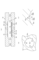
- FIG. 5 (a) is a cross-sectional view showing the configuration of the mold 30, (b) is a cross-sectional view taken along line C-C of (a), and (c) is a cross-sectional view showing an enlarged view of the groove portion 35 in (b).
- the mold 30 is formed in a rectangular parallelepiped shape, and has an internal space 31 inside which the balloon 13 is formed.
- the internal space 31 is an elongated space extending in the longitudinal direction of the mold 30, and has a shape corresponding to the shape of the balloon 13. Therefore, as shown in FIG. 5(b), the cross-sectional shape of the internal space 31 (more specifically, the shape of the cross-section perpendicular to the longitudinal direction of the internal space 31) is circular throughout the entire longitudinal area.
- the internal space 31 has a space 31a that forms the base end leg portion 13a of the balloon 13, a space 31b that forms the base end tapered portion 13b, a space 31c that forms the straight tube portion 13c, a space 31d that forms the tip end tapered portion 13d, and a space 31e that forms the tip end leg portion 13e.
- Each of these spaces 31a to 31e has a shape that corresponds to each of the portions 13a to 13e of the balloon 13.
- the mold 30 has an inner wall surface 32 that forms the internal space 31.
- the inner wall surface 32 is a surface that surrounds the internal space 31.
- the surface roughness of the inner wall surface 32 is constant over the entire area of the inner wall surface 32.
- the inner wall surface 32a (corresponding to the wall surface portion) that forms the space portion 31c (corresponding to the "space portion” described in the claims) for the straight pipe portion 13c has multiple (specifically, three) groove portions 35 formed therein. These groove portions 35 extend in the longitudinal direction of the internal space 31 and are disposed at equal intervals in the circumferential direction of the inner wall surface 32.
- each groove 35 has a cross section (more specifically, a cross section perpendicular to the longitudinal direction of the groove 35) that is valley-shaped, in other words V-shaped.
- the cross-sectional shape of the groove 35 corresponds to the cross-sectional shape (mountain shape) of the linear protrusion 20.
- the groove 35 has two side surfaces 35b (corresponding to the inner surface of the groove 35) that form the valley shape. These side surfaces 35b are adjacent to each other via the bottom 35a (valley bottom) of the groove 35. In this case, the width of the groove 35 decreases toward the bottom 35a of the groove 35.
- a rough surface portion 36 having a surface roughness greater than that of the inner wall surface 32 (32a) is formed on each side surface 35b of the groove portion 35.
- the rough surface portion 36 is formed over the entire area of each side surface 35b of the groove portion 35.
- the surface roughness of the rough surface portion 36 is constant over the entire area of the rough surface portion 36. Note that in FIG. 5(a), the rough surface portion 36 is shown with dot hatching.
- Figure 6 is a perspective view showing the parison 37.
- Figure 7 (a) is a cross-sectional view showing the state in which the parison 37 has been expanded in the internal space 31 of the mold 30, and (b) is a cross-sectional view taken along line D-D of (a).
- the parison 37 is formed in a cylindrical shape from a resin material, for example, by extrusion molding.
- the parison 37 has multiple (specifically, three) protrusions 38 protruding from its outer circumferential surface. These protrusions 38 are the bases of the linear protrusions 20 of the balloon 13.
- the shape of the cross section of the protrusions 38 is a mountain shape that protrudes radially outward from the parison 37, specifically a pentagonal shape (in other words, a home plate shape).
- Each protrusion 38 extends in the longitudinal direction of the parison 37, specifically over the entire longitudinal area of the parison 37.
- the protrusions 38 also have two side surfaces 38b (corresponding to the surfaces of the protrusions 38) that form the mountain shape. These side surfaces 38b are adjacent to each other via the top 38a of the protrusion 38.
- a placement process is performed in which the parison 37 is placed in the internal space 31 of the mold 30.
- the parison 37 is placed in the internal space 31 with its longitudinal direction facing the longitudinal direction of the internal space 31. This positions the parison 37 across each of the space portions 31a to 31e of the internal space 31.
- a stretching process is performed in which the parison 37 is stretched in the longitudinal direction.
- an expansion process is performed in which the parison 37 is expanded in the internal space 31 of the mold 30, thereby bringing the outer circumferential surface of the parison 37 into close contact with the inner wall surface 32.
- a pressurized fluid such as nitrogen is introduced into the interior of the parison 37 to pressurize the interior of the parison 37, thereby expanding the parison 37.
- a pressurized fluid is introduced into the parison 37 using a fluid supply device (not shown).
- the fluid supply device is capable of adjusting the amount of pressurized fluid introduced to adjust the pressurized pressure inside the parison 37.
- the parison 37 is expanded while being heated by a heater (not shown) provided in the mold 30.
- the heater is capable of adjusting the heating temperature of the parison 37.
- each linear protrusion 20 is formed in the straight tube portion 13c of the balloon 13.
- the protrusion 38 of the parison 37 is forced into the groove 35, forcing the protrusion 38 into close contact with each side surface 35b (each rough surface portion 36) of the groove 35, thereby forming a rough surface region 25 on each side surface 20b of the linear protrusion 20.
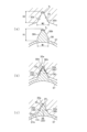
- Figure 8 is a cross-sectional view showing the flow when the protruding portion 38 of the parison 37 is pressed into the groove portion 35 of the mold 30 during the expansion process.
- the width W1 (maximum width) of the protrusion 38 is smaller than the width W2 (maximum width) of the groove 35.
- the height H1 of the protrusion 38 is greater than the depth H2 of the groove 35.
- the height H1 of the protrusion 38 is the height from the outer peripheral surface of the parison 37.
- the angle a formed by each side surface 38b of the protrusion 38 is greater than the angle b formed by each side surface 35b of the groove 35.
- a first expansion process is performed in which the parison 37 is expanded and each protrusion 38 of the parison 37 is inserted into the groove 35.
- the parison 37 is expanded by pressurizing the inside of the parison 37 with a relatively low first pressure P1.
- the parison 37 can be expanded relatively slowly, so that the protrusion 38 can be inserted into the groove 35 reliably.
- the width W1 of the protrusion 38 is smaller than the width W2 of the groove 35, so that the protrusion 38 can be inserted into the groove 35 easily.
- the parison 37 is expanded while being heated at a relatively low first temperature T1.
- the pressure inside the parison 37 i.e., the first pressure P1 is increased relatively slowly, and the heating temperature of the parison 37 (i.e., the first temperature T1) is increased relatively slowly.
- the pressure inside the parison 37 may be kept constant, and the heating temperature of the parison 37 may be kept constant.
- a second expansion step is performed in which the parison 37 is further expanded and each protrusion 38 is pushed into the groove 35, thereby adhering each protrusion 38 to each side surface 35b (i.e., the rough surface portion 36) of the groove 35.
- the parison 37 is expanded by pressurizing the inside of the parison 37 with a second pressure P2 higher than the first pressure P1.
- the protrusion 38 can be strongly pushed into the groove 35 and adhered to each side surface 35b. This allows the rough surface region 25 to be suitably formed on the linear protrusion 20.
- the parison 37 is expanded while being heated to a second temperature T2 higher than the first temperature T1.
- the protrusion 38 of the parison 37 can be pushed into the groove 35 in a softened state, which makes it easier to bring the protrusion 38 into close contact with each side surface 35b (rough surface portion 36) of the groove 35. Therefore, in this respect as well, the rough surface region 25 can be suitably formed on the linear protrusion 20.
- the pressure inside the parison 37 i.e., the second pressure P2
- the heating temperature of the parison 37 i.e., the second temperature T2
- the pressure inside the parison 37 may be constant
- the heating temperature of the parison 37 may be constant.
- each side 38b of the protrusion 38 is greater than the angle b between each side 35b of the groove 35. Therefore, when the protrusion 38 is pressed into the groove 35, the protrusion 38 can be deformed to fit each side 35b of the groove 35 and can be firmly attached to each side 35b (i.e., the rough surface portion 36). This makes it possible to suitably form the rough surface region 25 on the mountain-shaped linear protrusion 20.
- the angle a between the side surfaces 38b of the protrusion 38 is larger than the angle b between the side surfaces 35b of the groove 35, when the protrusion 38 is pushed into the groove 35, the protrusion 38 first abuts against the side surfaces 35b of the groove 35 (see FIG. 8(b)), and then abuts against the bottom 35a of the groove 35 (see FIG. 8(c)). In this case, the protrusion 38 can be pushed into the bottom 35a of the groove 35 while being deformed so as to conform to the side surfaces 35b of the groove 35. Therefore, the protrusion 38 can be suitably attached to the entire side surfaces 35b of the groove 35 (and thus the rough surface portion 36), and the rough surface region 25 can be suitably formed on the linear protrusion 20.
- a cutting process is performed to cut off the excess portions on both ends of the parison expansion body 37A. This forms the balloon 13, completing the manufacture of the balloon 13.
- subsequent processes include joining the balloon 13 to the catheter body 11 and joining the hub 12 to the catheter body 11. This completes the entire manufacturing process.
- a guiding catheter is inserted into a sheath introducer inserted into a blood vessel, and the tip opening of the guiding catheter is introduced to the entrance of the coronary artery.
- a guidewire G is inserted into the guiding catheter, and the inserted guidewire G is introduced from the entrance of the coronary artery through the lesion to the peripheral area.
- the balloon catheter 10 is introduced into the guiding catheter along the guide wire G.
- the balloon 13 is introduced (positioned) toward the lesion while being pushed and pulled.
- the balloon 13 is kept in a contracted state.
- the linear protrusion 20 is covered from the outer periphery by the wing portion 21 (see FIG. 4(b)). Therefore, when the balloon 13 is introduced, the rough surface region 25 formed on the linear protrusion 20 can be prevented from sliding against the tube wall. This makes it possible to prevent a decrease in the passability of the balloon 13 when the rough surface region 25 is formed on the linear protrusion 20.
- the balloon 13 When the balloon 13 reaches the lesion, the balloon 13 is inflated. This causes the linear protrusion 20 to be pressed against the lesion, causing a cut (crack) in the lesion. This cut can then be used as a trigger to destroy the lesion, allowing the lesion to expand outward. At this time, the rough surface region 25 of the linear protrusion 20 comes into contact with the lesion, preventing the balloon 13 from slipping. This makes it possible to suitably expand the lesion at the desired location.
- the balloon 13 After the balloon 13 has finished expanding the lesion, the balloon 13 is deflated. The balloon catheter 10 is then pulled out of the body in this deflated state. This completes the entire procedure.
- the balloon catheter 10 is primarily used to pass through blood vessels and treat blood vessels such as the coronary arteries, femoral arteries, and pulmonary arteries, but it can also be used in "tubes" and "body cavities” within the body, such as the urinary tract and digestive tract, other than blood vessels.
- the surface roughness of the straight tube portion 13c of the balloon 13 is smaller than that of the rough surface region 25 of the linear protrusion 20. Since the surface of the straight tube portion 13c has a significantly larger area than the surface of the linear protrusion 20, in this case, the reduced surface roughness of the straight tube portion 13c can reduce the sliding resistance when the balloon 13 is introduced into the blood vessel. This makes it possible to prevent the balloon 13 from slipping when inflated, while suppressing a decrease in the passage of the balloon 13 through the blood vessel.
- the rough surface region 25 is formed on the entire surface of the linear protrusion 20 (specifically, the entire surface of each side surface 20b), but the rough surface region may be formed on only a portion of the surface of the linear protrusion 20.
- FIG. 9 A specific example is shown in FIG. 9.
- a notch 41 is provided in each linear protrusion 40.
- Multiple notches 41 are provided in each linear protrusion 40.
- Each notch 41 is positioned in the linear protrusion 40 so as to divide the linear protrusion 40 into approximately equal parts (specifically, three equal parts).
- the linear protrusion 40 is divided into a plurality of regions 40a to 40c by each notch 41.
- Each of these regions 40a to 40c includes a base end region 40a located on the base end side, a tip end region 40b located on the tip end side, and an intermediate region 40c located between the base end region 40a and the tip end region 40b.
- a rough surface region 45 having a greater surface roughness than the surface of the straight pipe section 13c is formed on the surface of the intermediate region 40c.
- the rough surface region 45 is not formed on the surface of the base end region 40a and the surface of the tip end region 40b. Therefore, in this example, the rough surface region 45 is formed only in the intermediate region 40c in the linear protrusion 40.
- the above configuration makes it possible to prevent the sliding resistance from increasing even if the distal end region 40b or the proximal end region 40a of the linear protrusion 40 protrudes from the wing portion 21 and slides against the tube wall when the balloon 13 is introduced into the blood vessel in a contracted state. This makes it possible to further prevent the passage of the balloon 13 through the blood vessel from decreasing.
- the surface roughness of the rough surface region 25 may be smaller toward the longitudinal ends of the linear protrusion 20.
- the surface roughness of the rough surface region 25 is maximum at the longitudinal center of the linear protrusion 20.
- the surface roughness of the rough surface region 25 is then made smaller from the longitudinal center toward one end of the linear protrusion 20, and is also made smaller from the longitudinal center toward the other end of the linear protrusion 20.
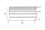
- FIG. 10 is an enlarged side view of the linear protrusion 50 on which a plurality of rough surface regions 53 are formed.
- a plurality of rough surface regions 53 are formed on each side surface 50a of the linear protrusion 50.
- Each rough surface region 53 extends in the longitudinal direction of the linear protrusion 50, and more specifically, extends over the entire longitudinal area of the linear protrusion 50.
- each rough surface region 53 is arranged so that the interval between adjacent rough surface regions 53 becomes smaller toward the protruding tip side of the linear protrusion 50. Therefore, each rough surface region 53 is arranged so that it becomes denser toward the protruding tip side of the linear protrusion 50.
- the protruding tip side of the linear protrusion 50 is primarily in contact.
- the rough surface area 53 is arranged so that it becomes denser toward the protruding tip side of the linear protrusion 50, so that the balloon 13 can be suitably prevented from slipping when the balloon 13 is inflated.
- the rough surface regions 53 are arranged so that they become less dense toward the protruding base end side of the linear protrusion 50 (the side opposite the protruding tip end), so the sliding resistance when the balloon 13 is introduced into the blood vessel can be reduced compared to when the rough surface regions 53 are arranged densely over the entire area of each side surface 50a of the linear protrusion 50. This makes it possible to preferably prevent the balloon 13 from slipping while further preventing a decrease in the passability of the balloon 13.
- the rough surface region 25 may be formed so that the surface roughness increases toward the protruding tip of the linear protrusion 20. In this case, it is possible to suitably prevent the balloon 13 from slipping when the balloon 13 is inflated. Furthermore, in this configuration, the surface roughness of the rough surface region 25 decreases toward the protruding base end of the linear protrusion 20. Therefore, compared to when the surface roughness of the entire rough surface region 25 is increased, it is possible to reduce the sliding resistance when the balloon 13 is introduced into the blood vessel. As a result, similar to the configuration of (3) above, it is possible to suitably prevent the balloon 13 from slipping while further suppressing a decrease in the passability of the balloon 13.
- the dimensional relationship between the groove 35 of the mold 30 and the protruding portion 38 of the parison 37 is not necessarily limited to that of the above embodiment.
- the height H1 of the protruding portion 38 may be smaller than the depth H2 of the groove 35, or may be the same as the depth H2 of the groove 35. In this case, the entire protruding portion 38 can be reliably inserted into the groove 35.
- the angle a between each side surface 38b of the protruding portion 38 may be smaller than the angle b between each side surface 35b of the groove 35. In this case, it is possible to make it easier for the protruding portion 38 of the parison 37 to enter the groove 35.
- the cross-sectional shape of the groove of the mold 30 may be changed as shown in FIG. 11.
- the cross-sectional shape of the groove 55 is a valley shape, as in the above embodiment. Therefore, the groove 55 has two side surfaces 56 that form a valley shape.
- the angle that these side surfaces 56 make with respect to the width direction of the groove 55 changes midway.
- the above angle changes between the side surface portion 56a in the open portion 55a of the groove 55 and the side surface portion 56b that is located on the inner side of the groove than the open portion 55a.
- the angle c that the side surface portion 56a makes with respect to the width direction of the groove 55 is larger than the angle d that the side surface portion 56b makes with respect to the width direction of the groove 55.
- the angle c is, for example, 90°.
- the above configuration makes it possible to prevent the protrusion 38 of the parison 37 that has entered the groove 55 from shifting along the side surface 56 of the groove 55 during the expansion process. This makes it possible to prevent problems such as the protrusion 38 being shifted out of the groove 55, which would result in the roughened surface area 25 not being properly formed on the side surface 20b of the linear protrusion 20.
- the tapered portions 13b and 13d of the balloon 13 are used to expand the lesion, the tapered portions 13b and 13d come into contact with the lesion at an angle, and as a reaction to this, the tapered portions 13b and 13d are pushed obliquely by the lesion, which may cause the balloon 13 to slip in the axial direction.
- the surface roughness of the surfaces of the tapered portions 13b and 13d of the balloon 13 may be made greater than the surface roughness of the surface of the straight tube portion 13c, as shown in FIG. 12.
- the surfaces of the tapered portions 13b and 13d come into contact with the lesion, which can prevent the tapered portions 13b and 13d from slipping in the axial direction, and therefore the balloon 13 from slipping in the axial direction.
- the surfaces of the tapered portions 13b and 13d are shown with dot hatching.
- the surface roughness of the surfaces of the tapered portions 13b and 13d is smaller than the surface roughness of the rough surface region 25 of the linear protrusion 20. This makes it possible to obtain the above-mentioned effect while suppressing a decrease in passability when the balloon 13 is introduced into a blood vessel. Note that the surface roughness of only one of the tapered portions 13b and 13d may be made larger.
- the straight tube portion 13c of the balloon 13 has a linear protrusion 20 (first linear protrusion) protruding from its surface.
- the distal tapered portion 13d of the balloon 13 may have a linear protrusion (second linear protrusion) protruding from its surface.
- a rough surface area having a greater surface roughness than the surface of the straight tube portion 13c may be formed on the surface of the second linear protrusion. This can further prevent the balloon 13 from slipping when it is inflated.
- a linear protrusion (third linear protrusion) protruding from the surface of the base end taper portion 13b of the balloon 13 may be provided, and a rough surface area having a greater surface roughness than the surface of the straight tube portion 13c may be formed on the surface of the third linear protrusion.
- the rough surface region 25 is formed on each side surface 20b of the linear protrusion 20 during the expansion process in which the parison 37 is expanded, but the method of forming the rough surface region 25 is not necessarily limited to this.
- the rough surface region 25 may be formed by, for example, scraping the side surface 20b of the linear protrusion 20.
Landscapes
- Health & Medical Sciences (AREA)
- Heart & Thoracic Surgery (AREA)
- Life Sciences & Earth Sciences (AREA)
- Engineering & Computer Science (AREA)
- Anesthesiology (AREA)
- Child & Adolescent Psychology (AREA)
- Biophysics (AREA)
- Pulmonology (AREA)
- Biomedical Technology (AREA)
- Hematology (AREA)
- Animal Behavior & Ethology (AREA)
- General Health & Medical Sciences (AREA)
- Public Health (AREA)
- Veterinary Medicine (AREA)
- Manufacturing & Machinery (AREA)
- Media Introduction/Drainage Providing Device (AREA)
Priority Applications (6)
| Application Number | Priority Date | Filing Date | Title |
|---|---|---|---|
| CN202380051189.4A CN119403591A (zh) | 2022-11-30 | 2023-11-01 | 球囊导管及球囊导管的制造方法 |
| AU2023407024A AU2023407024A1 (en) | 2022-11-30 | 2023-11-01 | Balloon catheter and method of producing balloon catheter |
| EP23897366.3A EP4563182A4 (en) | 2022-11-30 | 2023-11-01 | BALLOON CATHETER AND METHOD FOR MANUFACTURING THE SAME |
| JP2024561273A JP7724386B2 (ja) | 2022-11-30 | 2023-11-01 | バルーンカテーテル及びバルーンカテーテルの製造方法 |
| KR1020257001513A KR20250023550A (ko) | 2022-11-30 | 2023-11-01 | 풍선 카테터 및 풍선 카테터의 제조 방법 |
| US19/068,499 US20250195849A1 (en) | 2022-11-30 | 2025-03-03 | Balloon catheter and method of producing balloon catheter |
Applications Claiming Priority (2)
| Application Number | Priority Date | Filing Date | Title |
|---|---|---|---|
| JP2022192303 | 2022-11-30 | ||
| JP2022-192303 | 2022-11-30 |
Related Child Applications (1)
| Application Number | Title | Priority Date | Filing Date |
|---|---|---|---|
| US19/068,499 Continuation US20250195849A1 (en) | 2022-11-30 | 2025-03-03 | Balloon catheter and method of producing balloon catheter |
Publications (1)
| Publication Number | Publication Date |
|---|---|
| WO2024116710A1 true WO2024116710A1 (ja) | 2024-06-06 |
Family
ID=91323389
Family Applications (1)
| Application Number | Title | Priority Date | Filing Date |
|---|---|---|---|
| PCT/JP2023/039483 Ceased WO2024116710A1 (ja) | 2022-11-30 | 2023-11-01 | バルーンカテーテル及びバルーンカテーテルの製造方法 |
Country Status (7)
| Country | Link |
|---|---|
| US (1) | US20250195849A1 (https=) |
| EP (1) | EP4563182A4 (https=) |
| JP (1) | JP7724386B2 (https=) |
| KR (1) | KR20250023550A (https=) |
| CN (1) | CN119403591A (https=) |
| AU (1) | AU2023407024A1 (https=) |
| WO (1) | WO2024116710A1 (https=) |
Cited By (1)
| Publication number | Priority date | Publication date | Assignee | Title |
|---|---|---|---|---|
| WO2026079135A1 (ja) * | 2024-10-10 | 2026-04-16 | 株式会社グッドマン | カテーテル用バルーン、及びカテーテル用バルーンの製造方法 |
Citations (5)
| Publication number | Priority date | Publication date | Assignee | Title |
|---|---|---|---|---|
| US20100036314A1 (en) * | 2008-07-25 | 2010-02-11 | Cook Incorporated | Balloon catheter and method for making same |
| WO2020012850A1 (ja) * | 2018-07-09 | 2020-01-16 | 株式会社グッドマン | バルーンカテーテル |
| WO2020250611A1 (ja) * | 2019-06-11 | 2020-12-17 | 株式会社カネカ | バルーンカテーテル用のバルーンおよびバルーンカテーテルの製造方法 |
| WO2020255923A1 (ja) | 2019-06-21 | 2020-12-24 | 株式会社グッドマン | バルーンカテーテル |
| JP2021104223A (ja) * | 2019-12-26 | 2021-07-26 | 株式会社カネカ | バルーンカテーテルの製造方法および金型 |
Family Cites Families (3)
| Publication number | Priority date | Publication date | Assignee | Title |
|---|---|---|---|---|
| US6786889B1 (en) * | 1999-03-31 | 2004-09-07 | Scimed Life Systems, Inc | Textured and/or marked balloon for stent delivery |
| US11577056B2 (en) * | 2018-01-16 | 2023-02-14 | Aspero Medical, Inc. | Medical devices including textured inflatable balloons |
| JP7747734B2 (ja) * | 2021-03-15 | 2025-10-01 | 株式会社カネカ | バルーンカテーテル用バルーン |
-
2023
- 2023-11-01 WO PCT/JP2023/039483 patent/WO2024116710A1/ja not_active Ceased
- 2023-11-01 AU AU2023407024A patent/AU2023407024A1/en active Pending
- 2023-11-01 CN CN202380051189.4A patent/CN119403591A/zh active Pending
- 2023-11-01 KR KR1020257001513A patent/KR20250023550A/ko active Pending
- 2023-11-01 JP JP2024561273A patent/JP7724386B2/ja active Active
- 2023-11-01 EP EP23897366.3A patent/EP4563182A4/en active Pending
-
2025
- 2025-03-03 US US19/068,499 patent/US20250195849A1/en active Pending
Patent Citations (5)
| Publication number | Priority date | Publication date | Assignee | Title |
|---|---|---|---|---|
| US20100036314A1 (en) * | 2008-07-25 | 2010-02-11 | Cook Incorporated | Balloon catheter and method for making same |
| WO2020012850A1 (ja) * | 2018-07-09 | 2020-01-16 | 株式会社グッドマン | バルーンカテーテル |
| WO2020250611A1 (ja) * | 2019-06-11 | 2020-12-17 | 株式会社カネカ | バルーンカテーテル用のバルーンおよびバルーンカテーテルの製造方法 |
| WO2020255923A1 (ja) | 2019-06-21 | 2020-12-24 | 株式会社グッドマン | バルーンカテーテル |
| JP2021104223A (ja) * | 2019-12-26 | 2021-07-26 | 株式会社カネカ | バルーンカテーテルの製造方法および金型 |
Non-Patent Citations (1)
| Title |
|---|
| See also references of EP4563182A4 |
Cited By (1)
| Publication number | Priority date | Publication date | Assignee | Title |
|---|---|---|---|---|
| WO2026079135A1 (ja) * | 2024-10-10 | 2026-04-16 | 株式会社グッドマン | カテーテル用バルーン、及びカテーテル用バルーンの製造方法 |
Also Published As
| Publication number | Publication date |
|---|---|
| EP4563182A4 (en) | 2025-07-09 |
| EP4563182A1 (en) | 2025-06-04 |
| AU2023407024A1 (en) | 2025-03-13 |
| CN119403591A (zh) | 2025-02-07 |
| US20250195849A1 (en) | 2025-06-19 |
| JP7724386B2 (ja) | 2025-08-15 |
| KR20250023550A (ko) | 2025-02-18 |
| JPWO2024116710A1 (https=) | 2024-06-06 |
Similar Documents
| Publication | Publication Date | Title |
|---|---|---|
| CN112203712B (zh) | 球囊导管 | |
| US6849062B2 (en) | Catheter having a low-friction guidewire lumen and method of manufacture | |
| US8303539B2 (en) | Preform and balloon having a non-uniform thickness | |
| JP6975857B2 (ja) | バルーンカテーテル | |
| KR102736802B1 (ko) | 풍선 카테터(balloon catheter) | |
| WO2024116710A1 (ja) | バルーンカテーテル及びバルーンカテーテルの製造方法 | |
| JP7808100B2 (ja) | バルーンカテーテル用バルーン及びバルーンカテーテルの製造方法 | |
| WO2003039628A2 (en) | Balloon catheter with non-slip balloon | |
| JP7547634B2 (ja) | バルーンカテーテル | |
| JP2001190678A (ja) | 医療用ロングバルーンおよびこのロングバルーンを有するバルーンカテーテル。 | |
| JP7751131B2 (ja) | バルーンカテーテル及びバルーンカテーテルの製造方法 | |
| RU2814999C2 (ru) | Баллонный катетер | |
| CA3140474C (en) | Balloon catheter | |
| WO2025079330A1 (ja) | バルーンカテーテル及びバルーンカテーテルの製造方法 | |
| HK40043633B (en) | Balloon catheter | |
| HK40043640A (en) | Balloon catheter | |
| HK40043640B (zh) | 球囊导管 |
Legal Events
| Date | Code | Title | Description |
|---|---|---|---|
| 121 | Ep: the epo has been informed by wipo that ep was designated in this application |
Ref document number: 23897366 Country of ref document: EP Kind code of ref document: A1 |
|
| WWE | Wipo information: entry into national phase |
Ref document number: 2024561273 Country of ref document: JP |
|
| WWE | Wipo information: entry into national phase |
Ref document number: 202380051189.4 Country of ref document: CN |
|
| ENP | Entry into the national phase |
Ref document number: 20257001513 Country of ref document: KR Kind code of ref document: A |
|
| WWE | Wipo information: entry into national phase |
Ref document number: 1020257001513 Country of ref document: KR |
|
| WWP | Wipo information: published in national office |
Ref document number: 202380051189.4 Country of ref document: CN |
|
| WWP | Wipo information: published in national office |
Ref document number: 1020257001513 Country of ref document: KR |
|
| WWE | Wipo information: entry into national phase |
Ref document number: AU2023407024 Country of ref document: AU |
|
| WWE | Wipo information: entry into national phase |
Ref document number: 2023897366 Country of ref document: EP |
|
| WWE | Wipo information: entry into national phase |
Ref document number: 202517018026 Country of ref document: IN |
|
| ENP | Entry into the national phase |
Ref document number: 2023897366 Country of ref document: EP Effective date: 20250227 |
|
| ENP | Entry into the national phase |
Ref document number: 2023407024 Country of ref document: AU Date of ref document: 20231101 Kind code of ref document: A |
|
| REG | Reference to national code |
Ref country code: BR Ref legal event code: B01A Ref document number: 112025006896 Country of ref document: BR |
|
| WWP | Wipo information: published in national office |
Ref document number: 202517018026 Country of ref document: IN |
|
| WWP | Wipo information: published in national office |
Ref document number: 2023897366 Country of ref document: EP |
|
| NENP | Non-entry into the national phase |
Ref country code: DE |
|
| ENP | Entry into the national phase |
Ref document number: 112025006896 Country of ref document: BR Kind code of ref document: A2 Effective date: 20250407 |