WO2024116635A1 - 電池パック - Google Patents
電池パック Download PDFInfo
- Publication number
- WO2024116635A1 WO2024116635A1 PCT/JP2023/037805 JP2023037805W WO2024116635A1 WO 2024116635 A1 WO2024116635 A1 WO 2024116635A1 JP 2023037805 W JP2023037805 W JP 2023037805W WO 2024116635 A1 WO2024116635 A1 WO 2024116635A1
- Authority
- WO
- WIPO (PCT)
- Prior art keywords
- battery
- liquid
- case
- batteries
- holder
- Prior art date
- Legal status (The legal status is an assumption and is not a legal conclusion. Google has not performed a legal analysis and makes no representation as to the accuracy of the status listed.)
- Ceased
Links
Images


Classifications
-
- H—ELECTRICITY
- H01—ELECTRIC ELEMENTS
- H01M—PROCESSES OR MEANS, e.g. BATTERIES, FOR THE DIRECT CONVERSION OF CHEMICAL ENERGY INTO ELECTRICAL ENERGY
- H01M10/00—Secondary cells; Manufacture thereof
- H01M10/60—Heating or cooling; Temperature control
- H01M10/61—Types of temperature control
- H01M10/613—Cooling or keeping cold
-
- H—ELECTRICITY
- H01—ELECTRIC ELEMENTS
- H01M—PROCESSES OR MEANS, e.g. BATTERIES, FOR THE DIRECT CONVERSION OF CHEMICAL ENERGY INTO ELECTRICAL ENERGY
- H01M10/00—Secondary cells; Manufacture thereof
- H01M10/60—Heating or cooling; Temperature control
- H01M10/64—Heating or cooling; Temperature control characterised by the shape of the cells
- H01M10/643—Cylindrical cells
-
- H—ELECTRICITY
- H01—ELECTRIC ELEMENTS
- H01M—PROCESSES OR MEANS, e.g. BATTERIES, FOR THE DIRECT CONVERSION OF CHEMICAL ENERGY INTO ELECTRICAL ENERGY
- H01M10/00—Secondary cells; Manufacture thereof
- H01M10/60—Heating or cooling; Temperature control
- H01M10/65—Means for temperature control structurally associated with the cells
- H01M10/656—Means for temperature control structurally associated with the cells characterised by the type of heat-exchange fluid
- H01M10/6567—Liquids
-
- H—ELECTRICITY
- H01—ELECTRIC ELEMENTS
- H01M—PROCESSES OR MEANS, e.g. BATTERIES, FOR THE DIRECT CONVERSION OF CHEMICAL ENERGY INTO ELECTRICAL ENERGY
- H01M50/00—Constructional details or processes of manufacture of the non-active parts of electrochemical cells other than fuel cells, e.g. hybrid cells
- H01M50/20—Mountings; Secondary casings or frames; Racks, modules or packs; Suspension devices; Shock absorbers; Transport or carrying devices; Holders
- H01M50/204—Racks, modules or packs for multiple batteries or multiple cells
- H01M50/207—Racks, modules or packs for multiple batteries or multiple cells characterised by their shape
- H01M50/213—Racks, modules or packs for multiple batteries or multiple cells characterised by their shape adapted for cells having curved cross-section, e.g. round or elliptic
-
- H—ELECTRICITY
- H01—ELECTRIC ELEMENTS
- H01M—PROCESSES OR MEANS, e.g. BATTERIES, FOR THE DIRECT CONVERSION OF CHEMICAL ENERGY INTO ELECTRICAL ENERGY
- H01M50/00—Constructional details or processes of manufacture of the non-active parts of electrochemical cells other than fuel cells, e.g. hybrid cells
- H01M50/30—Arrangements for facilitating escape of gases
- H01M50/342—Non-re-sealable arrangements
- H01M50/3425—Non-re-sealable arrangements in the form of rupturable membranes or weakened parts, e.g. pierced with the aid of a sharp member
-
- H—ELECTRICITY
- H01—ELECTRIC ELEMENTS
- H01M—PROCESSES OR MEANS, e.g. BATTERIES, FOR THE DIRECT CONVERSION OF CHEMICAL ENERGY INTO ELECTRICAL ENERGY
- H01M50/00—Constructional details or processes of manufacture of the non-active parts of electrochemical cells other than fuel cells, e.g. hybrid cells
- H01M50/30—Arrangements for facilitating escape of gases
- H01M50/35—Gas exhaust passages comprising elongated, tortuous or labyrinth-shaped exhaust passages
- H01M50/367—Internal gas exhaust passages forming part of the battery cover or case; Double cover vent systems
-
- Y—GENERAL TAGGING OF NEW TECHNOLOGICAL DEVELOPMENTS; GENERAL TAGGING OF CROSS-SECTIONAL TECHNOLOGIES SPANNING OVER SEVERAL SECTIONS OF THE IPC; TECHNICAL SUBJECTS COVERED BY FORMER USPC CROSS-REFERENCE ART COLLECTIONS [XRACs] AND DIGESTS
- Y02—TECHNOLOGIES OR APPLICATIONS FOR MITIGATION OR ADAPTATION AGAINST CLIMATE CHANGE
- Y02E—REDUCTION OF GREENHOUSE GAS [GHG] EMISSIONS, RELATED TO ENERGY GENERATION, TRANSMISSION OR DISTRIBUTION
- Y02E60/00—Enabling technologies; Technologies with a potential or indirect contribution to GHG emissions mitigation
- Y02E60/10—Energy storage using batteries
Definitions
- This disclosure relates to a battery pack containing multiple batteries.
- Patent Document 1 discloses a battery pack in which the batteries are housed in a space filled with a cooling liquid to cool the batteries.
- the battery may have a safety valve that opens when the internal pressure increases. In this configuration, gas is exhausted from the safety valve when there is an abnormality in the battery, preventing damage to the battery case due to the increase in internal pressure of the battery.
- the battery pack according to one aspect of the present disclosure is a battery pack having a case and a number of batteries housed within the case, the number of batteries having a safety valve that opens when the internal pressure rises to exhaust internal gas, and being immersed in a coolant within the case, the case having a liquid-sealed section in which the coolant is sealed, and a wall section provided below the liquid-sealed section and separating the liquid-sealed section from a space not containing coolant, the end portions of the number of batteries near the safety valves being in contact with or closely facing the surface of the wall section near the liquid-sealed section.
- the battery pack according to one aspect of the present disclosure can suppress an increase in the volume of the battery pack and an increase in the number of parts, and can also suppress the spread of thermal runaway among multiple batteries when an abnormality occurs in a battery.
- FIG. 1 is a perspective view of a battery pack according to an embodiment
- 2 is a cross-sectional view taken along line AA of FIG. 1.
- 2 is a cross-sectional view of a battery constituting the battery pack of the embodiment.
- FIG. 3 is a diagram corresponding to FIG. 2 and illustrating a state in which a battery is preferentially cooled when an abnormality occurs in the battery in the embodiment.
- FIG. 3 is a view corresponding to an enlarged view of a portion B in FIG. 2 in a battery pack according to another embodiment of the present invention.
- FIG. 5 is a schematic diagram showing the battery and the wall portion as viewed in the direction of the arrow C in FIG. 5 .
- FIG. 7 is a diagram corresponding to FIG.
- FIG. 3 is a view corresponding to FIG. 2 in a battery pack according to another embodiment of the present invention.
- the battery pack 1 is described as having a substantially rectangular parallelepiped outer shape.
- the X direction indicates the longitudinal direction of the battery pack 1 (case 10)
- the Y direction indicates the width direction of the battery pack 1 (case 10)
- the Z direction indicates the up-down direction (height direction) of the battery pack 1 (case 10).
- the X direction, Y direction, and Z direction are mutually perpendicular.
- the side where the cap 45 of the battery 30 shown in Figure 3 is provided is referred to as the "lower side”
- the opposite side is referred to as the "upper side”.
- Figure 1 is a perspective view of the battery pack 1, which is an example of an embodiment.
- Figure 2 is a cross-sectional view taken along line A-A in Figure 1 (a cross-sectional view taken along the XZ plane passing through the center of the battery pack 1 in the width direction).
- the battery pack 1 comprises a battery block 20 having a plurality of batteries 30, and a case 10 that houses the battery block 20.
- the batteries 30 are non-aqueous electrolyte secondary batteries such as lithium ion batteries, and although there are no particular limitations on the shape or size, cylindrical batteries are preferred. The following description will focus on the case where the batteries 30 are cylindrical batteries.
- the case 10 is box-shaped with an approximately rectangular parallelepiped exterior. Inside the case 10, a liquid-sealed portion 11 is provided in which insulating cooling liquid 50 is sealed, and a portion of each battery 30 is immersed in the cooling liquid 50 in the liquid-sealed portion 11. This allows the cooling liquid 50 to come into direct contact with each battery 30, improving the cooling performance of each battery 30.
- Each of the multiple batteries 30 has a safety valve 37 that opens when the internal pressure rises to exhaust internal gas.
- the case 10 is provided below the liquid-sealed portion 11 and has a first holder 61 (described below) that separates the liquid-sealed portion 11 from the liquid discharge chamber 12 below it.
- the liquid discharge chamber 12 corresponds to a space not filled with cooling liquid.
- the first holder 61 corresponds to a wall portion.
- the lower ends of the multiple batteries 30, which are the ends on the safety valve 37 side are in contact with or closely opposed to the liquid-sealed portion 11 side surface of the first holder 61. This makes it possible to suppress an increase in the volume of the battery pack 1 and an increase in the number of parts, as described below, and also suppresses the spread of thermal runaway between the multiple batteries 30 when an abnormality occurs in a battery 30.
- Battery pack 1 is primarily used as a power source for motive power.
- Battery pack 1 is used as a power source for motor-driven electric devices, such as electric vehicles, power tools, power-assisted bicycles, electric motorcycles, electric wheelchairs, electric tricycles, and electric carts.
- motor-driven electric devices such as electric vehicles, power tools, power-assisted bicycles, electric motorcycles, electric wheelchairs, electric tricycles, and electric carts.
- the use of battery pack 1 is not limited, and it may be used as a power source for various electric devices used indoors and outdoors, such as cleaners, radios, lighting devices, digital cameras, and video cameras, other than electric devices.
- the battery block 20 has a number of batteries 30 and a battery holder 60 into which both ends of the batteries 30 are inserted and held in the vertical direction Z.
- the battery block 20 is arranged in a portion of the interior of the case 10 that ranges from the upper end to the middle part in the vertical direction Z. This forms a liquid discharge chamber 12, which will be described later, at the lower end of the interior of the case 10.
- the battery 30 has a safety valve 37 that opens when the internal pressure rises to exhaust internal gas.
- the safety valve 37 is provided at the bottom end of the battery 30.
- the multiple batteries 30 are arranged in the case 10 along the vertical direction, with the first direction being the vertical direction, so that the safety valve 37 is located at the bottom end, which is the end on one side in the first direction. If the internal pressure of the battery 30 rises when an abnormality occurs in the battery 30, gas is exhausted from an exhaust hole 45a (see Figure 3) formed in the cap 45 that constitutes the safety valve 37.
- the battery holder 60 includes a first holder 61 that holds the lower side of the battery 30, and a second holder 62 that holds the upper side of the battery 30.
- the first holder 61 has a recess 63 into which the cap 45, which is the tip of the lower end of the battery 30, enters.
- a step 64 with a circular cross section is formed around the entire circumference at the open end of the recess 63.
- the lower end of the battery 30 is held in the step 64.
- the cap 45 constitutes the safety valve 37 of the battery 30.
- the case 10 is made of a metal such as aluminum or resin, and has a roughly rectangular parallelepiped outer shape. Specifically, the case 10 has two first side walls 10a, 10b arranged at both ends in the longitudinal direction X, and two second side walls 10c arranged at both ends in the width direction Y. The case 10 has the function of protecting the battery 30 housed therein from dust and water.
- a liquid-sealed portion 11 in which a cooling liquid 50 is sealed is provided inside the case 10.
- the liquid-sealed portion 11 also functions as a battery housing chamber in which multiple batteries 30 are housed.
- the liquid-sealed portion 11 is a portion partitioned by the case 10, the first holder 61, and the second holder 62, and is a portion in which the battery 30 is disposed except for both ends in the vertical direction Z.
- the liquid-sealed portion 11 is filled with a cooling liquid 50, and a portion of each battery 30 is immersed in the cooling liquid 50.
- the cooling liquid 50 occupies more than half of the volume of the liquid-sealed portion 11.
- the cooling liquid 50 is filled in the entire liquid-sealed portion 11.
- the cooling liquid 50 may be filled only in a portion of the liquid-sealed portion 11, and a space may be formed in the remaining portion. In this way, the battery 30 is directly cooled in contact with the cooling liquid 50, and the battery 30 can be efficiently cooled. This can improve the charging performance, durability, and safety of the battery 30.
- the cooling liquid 50 also has insulating properties. This can prevent a battery 30 from leaking electricity to other batteries 30 through the cooling liquid 50.
- Examples of the cooling liquid 50 include insulating oil, transformer oil, silicone oil, and fluorine-based inactive liquids such as hydrofluoroether.
- the liquid discharge chamber 12 is provided via the first holder 61 at the lower end of the inside of the case 10, below the liquid sealed portion 11.
- the liquid discharge chamber 12 is a space not filled with cooling liquid provided below the first holder 61.
- the first holder 61 is provided below the liquid sealed portion 11, and separates the liquid sealed portion 11 and the liquid discharge chamber 12 so that liquid does not flow between them. For this reason, the outer peripheral surface of the first holder 61 is fixed in close contact with the inner peripheral surface of the case 10, and the first holder 61 does not have a hole penetrating in the thickness direction.
- gas generated inside the battery 30 is exhausted from the exhaust hole 45a of the cap 45 (see FIG. 3).
- the part of the first holder 61 that is in contact with or closely facing the lower end of the abnormal battery 30 melts and is destroyed by contact with the high-temperature gas.
- the liquid discharge chamber 12 receives the cooling liquid 50 discharged from the liquid sealing part 11.
- the case 10 has an exhaust section 13, which is a through hole, at the lower end facing the liquid discharge chamber 12 in the first side wall 10a provided at one end (the right end in Figure 2) in the longitudinal direction X, which is the second direction.
- an exhaust section 13 exhausts gas from the liquid discharge chamber 12 to the outside of the case 10.
- the size of the exhaust section 13 is not particularly limited as long as it is large enough to exhaust the gas inside the case 10 and prevent the case 10 from bursting.
- the exhaust section 13 may be open at all times, but may also be configured to have the function of breaking open in response to an increase in pressure inside the case 10 when an abnormality occurs. This makes it possible to prevent dust and water from entering the case 10 while preventing the case 10 from bursting.
- the case 10 may have a covering member that covers the exhaust section 13. This can further prevent dust and water from entering the inside of the case 10.
- the covering member is fixed to the outer or inner surface of the case 10 so as to close the exhaust section 13, for example, by a fixing means such as an adhesive.
- the covering member may be made of a breathable, waterproof material such as Gore-Tex (registered trademark), which allows exhaust gas from inside the case 10 to pass through while blocking liquids such as water from the outside.
- the battery block 20 will be described with reference to Figure 2. As described above, the battery block 20 has a battery holder 60 into which both axial ends of the multiple batteries 30 are inserted and held.
- the battery block 20 includes a positive electrode terminal plate 70 that abuts against the lower surface of the first holder 61, and a negative electrode terminal plate 80 that abuts against the upper surface of the second holder 62.
- the positive electrode terminal plate 70 and the cap 45 that serves as the positive electrode external terminal of the battery 30 are electrically connected via a positive electrode lead portion (not shown).
- the negative electrode terminal plate 80 and the bottom of the exterior body 35 (see FIG. 3) that serves as the negative electrode external terminal of the battery 30 are electrically connected via a negative electrode lead portion (not shown).
- the positive electrode terminal plate 70 and the negative electrode terminal plate 80 connect the multiple batteries 30 in parallel.
- the battery holder 60 may be made of, for example, PC (polycarbonate) resin, high thermal conductivity PPS (polyphenylene sulfide) resin, resin containing heat dissipating filler, injection moldable thermosetting resin, etc. More specifically, the battery holder 60 may be made of phenolic resin, unsaturated polyester, unsaturated polyester mixed with a heat absorbing agent, etc. It is preferable that at least the first holder 61 of the battery holder 60 is made of a resin material that is easily melted and destroyed by contact with high-temperature gas exhausted from the battery 30 when an abnormality occurs in the battery 30.
- the recess 63 of the first holder 61 is a circular hole with a bottom formed in the upper surface of the first holder 61.
- a step 64 with a circular cross section is provided at the open end of the recess 63.
- the shoulder 46 (see Figure 3) on the outer peripheral surface of the battery 30, which is the lower end of the battery 30 and has an outer diameter larger than the outer diameter of the cap 45, fits into and comes into contact with the cylindrical portion of the step 64. This allows the underside of the battery 30 to be held in the first holder 61.
- a space is formed between the recess 63 and the outer surface of the cap 45. Therefore, a gap is formed between the exhaust hole 45a (described below) that opens into the outer peripheral surface of the cap 45 and the inner peripheral surface of the recess 63. Also, the lower end surface, which is the tip surface of the cap 45, and the bottom surface of the recess 63 closely face each other with a small gap between them.
- the exhaust hole 45a of the cap 45 is connected to the space within the recess 63.
- the plate thickness of the part where the bottom of the recess 63 is formed is large enough to be easily melted by contact with high-temperature gas.
- a portion of the positive electrode lead portion connected to the positive electrode terminal plate 70 is embedded near the recess 63 of the first holder 61.
- the portion of the positive electrode lead extending from the inner surface of the recess 63 of the first holder 61 is electrically connected to the cap 45.
- the positive electrode lead portion may be formed integrally with the positive electrode terminal plate 70.
- the second holder 62 includes a holding portion 65 that holds the upper end of the battery 30, and an opening 66 that exposes the bottom surface of the battery 30 to the top plate side of the case 10.
- the holding portion 65 of the second holder 62 is a circular hole formed in the lower surface of the second holder 62. The upper end of the battery 30 is fitted into the holding portion 65, thereby holding the upper side of the battery 30.
- the opening 66 is formed so as to penetrate the second holder 62 in the vertical direction.
- the negative electrode lead portion is connected to the bottom of the battery 30 through the opening 66.
- the negative electrode lead portion may be formed integrally with the negative electrode terminal plate 80.
- Figure 3 shows the battery 30 in the opposite up-down direction to the up-down direction when the battery 30 is incorporated into the battery pack 1 and used as shown in Figure 2.
- the bottom of the battery 30 shown in Figure 3 will be the upper side of the battery 30 when actually used.
- Battery 30 is a cylindrical battery and a lithium ion battery. Note that battery 30 is not limited to a cylindrical battery, and may be a prismatic battery, a laminated battery, or the like. Battery 30 may also be an aqueous battery or a non-aqueous battery. A lithium ion battery is preferably used as an example of a non-aqueous battery.
- the battery 30 has an electrode body 34, an electrolyte (not shown), and an exterior body 35 that contains the electrode body 34 and the electrolyte.
- the electrode body 34 has a positive electrode 31, a negative electrode 32, and a separator 33, and has a wound structure in which the positive electrode 31 and the negative electrode 32 are wound in a spiral shape with the separator 33 interposed therebetween.
- the exterior body 35 has a bottomed cylindrical shape that is open on the bottom side (upper side in Figure 3), and the opening of the exterior body 35 is sealed by a sealing body 36.
- the battery 30 includes insulating plates 38a, 38b arranged on the lower and upper sides of the electrode body 34 (upper and lower sides in FIG. 3).
- the positive electrode lead 39 attached to the positive electrode 31 extends through a through hole in the insulating plate 38a toward the sealing body 36
- the negative electrode lead 40 attached to the negative electrode 32 extends through a through hole in the insulating plate 38b toward the bottom side of the exterior body 35.
- the positive electrode lead 39 is connected by welding or the like to the surface of the internal terminal plate 41, which is the bottom plate of the sealing body 36, on the electrode body 34 side.
- the internal terminal plate 41 is electrically connected to the cap 45, which is the top plate of the sealing body 36 and serves as the positive electrode external terminal.
- the negative electrode lead 40 is connected by welding or the like to the inner surface of the bottom of the exterior body 35, and the bottom of the exterior body 35 serves as the negative electrode external terminal.
- the sealing body 36 has a structure in which, in order from the electrode body 34 side, an internal terminal plate 41, a first valve body 42, an insulating member 43, a second valve body 44, and a cap 45 are layered.
- Each member constituting the sealing body 36 is, for example, disk-shaped or ring-shaped, and each member except for the insulating member 43 is electrically connected to each other.
- the first valve body 42 and the second valve body 44 are connected to each other at their respective centers, and the insulating member 43 is interposed between their respective peripheral portions.
- the safety valve 37 of the sealing body 36 is composed of the first valve body 42, the second valve body 44, and the cap 45.
- the first valve body 42 deforms and breaks, pushing the second valve body 44 toward the cap 45, and the current path between the first valve body 42 and the second valve body 44 is cut off.
- the second valve body 44 breaks, and gas is exhausted from the exhaust hole 45a formed on the side of the convex portion of the cap 45.
- the position of the safety valve is not limited to this embodiment, and the safety valve may be provided at the bottom of the exterior body 35 of the battery 30, and the internal gas may be exhausted from the bottom when the internal pressure of the battery rises.
- the safety valve at the bottom of the battery 30 faces the bottom surface of the recess 63 provided on the surface of the first holder 61 on the battery 30 side, and the shoulder on the bottom side of the exterior body 35 of the battery 30 is fitted into the cylindrical portion of the step provided at the open end of the recess 63.
- the vertical orientation of the battery 30 when in use coincides with the vertical orientation in FIG. 3.
- the case 10 is provided with a first holder 61 below the liquid sealing portion 11, which separates the liquid sealing portion 11 from the liquid discharge chamber 12.
- the shoulder 46 at the lower end which is the safety valve side end of the multiple batteries 30, contacts the liquid sealing portion 11 side surface of the first holder 61, and the cap 45 closely faces the recess 63 on the liquid sealing portion 11 side surface of the first holder 61.
- the cooling liquid 50 when the cooling liquid 50 is discharged into the liquid discharge chamber 12 through the gap between the lower end of one of the batteries 30 and the first holder 61, the cooling liquid 50 flows and comes into contact with the lower end of that battery 30. Also, the cooling liquid 50 in the liquid sealing portion 11 flows as a whole toward the gap between the lower end of that battery 30 and the first holder 61. Therefore, the battery 30 is cooled preferentially over the other batteries 30, and the spread of thermal runaway among multiple batteries 30 when an abnormality occurs in one battery 30 can be suppressed.
- the case 10 is provided with a liquid discharge chamber 12 below the first holder 61.
- the liquid discharge chamber 12 receives the cooling liquid 50 discharged from the liquid sealing portion 11 when the first holder 61 is broken. This makes it possible to suppress leakage of the cooling liquid 50 from the liquid discharge chamber 12 to the outside of the case 10. Furthermore, even if the cooling liquid 50 is discharged to the outside of the case 10 through the exhaust portion 13, the speed at which the cooling liquid 50 moves in the vicinity of the battery 30 can be adjusted by adjusting the size of the exhaust portion 13. This makes it easier to achieve a balance between suppressing the discharge speed of the cooling liquid 50 to the outside of the case 10 and improving the cooling performance of the battery 30.
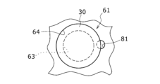
- FIG. 5 is a view corresponding to the enlarged view of part B in FIG. 2, in a battery pack 1a according to another example of the embodiment.
- FIG. 6 is a schematic view showing the state in which the batteries 30 and the first holder 61 in FIG. 5 are viewed in the direction of arrow C in FIG. 5.
- FIG. 7 is a view corresponding to FIG. 5, showing the state in which some of the batteries 30 are cooled preferentially when an abnormality occurs in the batteries 30, in another example of the embodiment.
- a small recess 81 having a circular cross section is formed in a portion of the circumference so as to cover both the step portion 64 of the multiple recesses 63 provided on the surface of the liquid-sealed portion 11 side of the first holder 61 and the portion adjacent to the step portion 64 on the radial outside. This reduces the distance between the recess 63 and the small recess 81 in the first holder 61. Therefore, when high-temperature gas is exhausted from the exhaust hole 45a (see Fig.
- the battery 30 can be cooled using the cooling liquid 50 discharged from the liquid-sealing portion 11 simply by forming a gap between a circumferential portion of the outer circumferential surface of the battery 30 and the first holder 61.
- the other configurations and functions are the same as those in Figures 1 to 3.
- FIG. 8 is a view corresponding to FIG. 2 of a battery pack 1b according to another embodiment.
- the case 90 has the same configuration as the case 10 shown in FIGS. 1 to 3, except that the bottom plate is removed and the exhaust section 13 (see FIG. 2) is omitted.
- the liquid discharge chamber 12 (see FIG. 2) is not formed below the first holder 61.
- the first holder 61 separates the liquid-sealed portion 11 from the space outside the case 90, which is the space not filled with cooling liquid. Furthermore, the lower surface 61a of the first holder 61, which is on the side of the space not filled with cooling liquid, forms the outer surface of the case 90.
- a gap is provided between the recess 63 of the first holder 61 and the cap 45 of the battery 30, but the inner surface of the recess 63 may be in contact with the outer surface of the cap 45, for example by being in close contact with the outer surface.
- the liquid sealed portion 11 and the space not filled with coolant are partitioned by the first holder 61, but this is not limited to this.
- a wall made of resin or metal may be provided inside the case 10, and this wall may separate the liquid sealed portion 11 and the space not filled with coolant so that liquid does not flow between them.
- the safety valve side ends of the multiple batteries 30 are brought into contact with or closely opposed to the liquid sealed portion 11 side surface of the wall.
- the positive terminal plate 70 for electrically connecting the positive external terminals of the batteries 30 and the negative terminal plate 80 for electrically connecting the bottom of the exterior body 35 (see FIG. 3) as the negative external terminal of the batteries 30 are provided outside both ends of the battery 30 in the vertical direction and arranged to face each other in the vertical direction.
- both the positive terminal plate 70 for electrically connecting the positive external terminals of the batteries 30 and the negative terminal plate 80 for electrically connecting the exterior body 35 (see FIG. 3) as the negative external terminal of the batteries 30 may be arranged on one side in the vertical direction of the battery 30.
- a plate material made of an insulating material may be interposed between the positive terminal plate 70 for electrically connecting the positive external terminals of the batteries 30 and the negative terminal plate 80 for electrically connecting the bottom of the exterior body 35 (see FIG. 3) as the negative external terminal of the batteries 30 to reliably prevent a short circuit between the positive terminal plate 70 and the negative terminal plate 80.
- a plate material made of an insulating material may be interposed between the positive terminal plate 70 for electrically connecting the positive external terminals of the batteries 30 and the negative terminal plate 80 for electrically connecting the bottom of the exterior body 35 (see FIG. 3) as the negative external terminal of the batteries 30 to reliably prevent a short circuit between the positive terminal plate 70 and the negative terminal plate 80.
- the multiple batteries 30 may be turned upside down, the positive terminal plate 70 and the negative terminal plate 80 may be provided on the upper side of the multiple batteries 30, and an exhaust section (safety valve) made of a thin section or the like may be formed on the bottom of the exterior body 35 that is on the lower side of each of the multiple batteries 30, and the exhaust section side end of each battery may be in contact with or adjacent to the wall of a battery holder or the like.
- an exhaust section safety valve
- a thin-walled portion may be provided in the wall of the battery holder, etc., and the thin-walled portion may be broken by the pressure of the gas discharged from the safety valve of the battery, forming a flow path in the wall.
- 1, 1a, 1b battery pack 10 case, 10a, 10b first side wall, 10c second side wall, 11 liquid sealing section, 12 liquid discharge chamber, 13 exhaust section, 16 exhaust path, 18 storage section, 20 battery block, 30 battery, 31 positive electrode, 32 negative electrode, 33 separator, 34 electrode body, 35 exterior body, 36 sealing body, 37 safety valve, 38a, 38b insulating plate, 39 positive electrode lead, 40 Negative electrode lead, 41 internal terminal plate, 42 first valve body, 43 insulating member, 44 second valve body, 45 cap (positive electrode external terminal), 45a exhaust hole, 46 shoulder, 50 coolant, 60 battery holder, 61 first holder, 61a surface, 62 second holder, 63 recess, 64 step, 65 holding part, 66 opening, 70 positive electrode terminal plate, 80 negative electrode terminal plate, 81 small recess, 90 case.
Landscapes
- Chemical & Material Sciences (AREA)
- Chemical Kinetics & Catalysis (AREA)
- Electrochemistry (AREA)
- General Chemical & Material Sciences (AREA)
- Engineering & Computer Science (AREA)
- Manufacturing & Machinery (AREA)
- Battery Mounting, Suspending (AREA)
- Gas Exhaust Devices For Batteries (AREA)
Priority Applications (3)
| Application Number | Priority Date | Filing Date | Title |
|---|---|---|---|
| EP23897292.1A EP4629412A4 (en) | 2022-11-30 | 2023-10-19 | BATTERY BLOCK |
| CN202380079763.7A CN120239924A (zh) | 2022-11-30 | 2023-10-19 | 电池组 |
| JP2024561238A JPWO2024116635A1 (https=) | 2022-11-30 | 2023-10-19 |
Applications Claiming Priority (2)
| Application Number | Priority Date | Filing Date | Title |
|---|---|---|---|
| JP2022-191304 | 2022-11-30 | ||
| JP2022191304 | 2022-11-30 |
Publications (1)
| Publication Number | Publication Date |
|---|---|
| WO2024116635A1 true WO2024116635A1 (ja) | 2024-06-06 |
Family
ID=91323586
Family Applications (1)
| Application Number | Title | Priority Date | Filing Date |
|---|---|---|---|
| PCT/JP2023/037805 Ceased WO2024116635A1 (ja) | 2022-11-30 | 2023-10-19 | 電池パック |
Country Status (4)
| Country | Link |
|---|---|
| EP (1) | EP4629412A4 (https=) |
| JP (1) | JPWO2024116635A1 (https=) |
| CN (1) | CN120239924A (https=) |
| WO (1) | WO2024116635A1 (https=) |
Cited By (2)
| Publication number | Priority date | Publication date | Assignee | Title |
|---|---|---|---|---|
| CN118694013A (zh) * | 2024-08-23 | 2024-09-24 | 杭州中宏聚能新能源科技有限公司 | 一种防漏液液冷储能柜 |
| CN119050545A (zh) * | 2024-10-29 | 2024-11-29 | 江苏科腾环境科技有限公司 | 一种储能电池柜用温度控制系统 |
Citations (4)
| Publication number | Priority date | Publication date | Assignee | Title |
|---|---|---|---|---|
| CN101160689A (zh) * | 2005-04-15 | 2008-04-09 | 戴姆勒-克莱斯勒股份公司 | 液冷式电池及操作该电池的方法 |
| JP2014060088A (ja) | 2012-09-19 | 2014-04-03 | Toshiba Corp | 二次電池装置および二次電池システム |
| JP2015138773A (ja) * | 2014-01-23 | 2015-07-30 | 睦月電機株式会社 | 冷却装置 |
| JP2021511642A (ja) * | 2018-01-29 | 2021-05-06 | コミサリア ア エナジー アトミック エ オックス エナジーズ オルタネティヴ | 電池モジュール、及び複数のモジュールを備えた電池 |
Family Cites Families (3)
| Publication number | Priority date | Publication date | Assignee | Title |
|---|---|---|---|---|
| US9685645B2 (en) * | 2014-07-16 | 2017-06-20 | Ford Global Technologies, Llc | Battery pack venting system for electrified vehicle |
| JP6772986B2 (ja) * | 2017-08-08 | 2020-10-21 | トヨタ自動車株式会社 | 電池パック |
| FR3114917B1 (fr) * | 2020-10-06 | 2023-05-12 | Commissariat Energie Atomique | Carter de batterie |
-
2023
- 2023-10-19 JP JP2024561238A patent/JPWO2024116635A1/ja active Pending
- 2023-10-19 WO PCT/JP2023/037805 patent/WO2024116635A1/ja not_active Ceased
- 2023-10-19 EP EP23897292.1A patent/EP4629412A4/en active Pending
- 2023-10-19 CN CN202380079763.7A patent/CN120239924A/zh active Pending
Patent Citations (4)
| Publication number | Priority date | Publication date | Assignee | Title |
|---|---|---|---|---|
| CN101160689A (zh) * | 2005-04-15 | 2008-04-09 | 戴姆勒-克莱斯勒股份公司 | 液冷式电池及操作该电池的方法 |
| JP2014060088A (ja) | 2012-09-19 | 2014-04-03 | Toshiba Corp | 二次電池装置および二次電池システム |
| JP2015138773A (ja) * | 2014-01-23 | 2015-07-30 | 睦月電機株式会社 | 冷却装置 |
| JP2021511642A (ja) * | 2018-01-29 | 2021-05-06 | コミサリア ア エナジー アトミック エ オックス エナジーズ オルタネティヴ | 電池モジュール、及び複数のモジュールを備えた電池 |
Non-Patent Citations (1)
| Title |
|---|
| See also references of EP4629412A1 |
Cited By (2)
| Publication number | Priority date | Publication date | Assignee | Title |
|---|---|---|---|---|
| CN118694013A (zh) * | 2024-08-23 | 2024-09-24 | 杭州中宏聚能新能源科技有限公司 | 一种防漏液液冷储能柜 |
| CN119050545A (zh) * | 2024-10-29 | 2024-11-29 | 江苏科腾环境科技有限公司 | 一种储能电池柜用温度控制系统 |
Also Published As
| Publication number | Publication date |
|---|---|
| JPWO2024116635A1 (https=) | 2024-06-06 |
| EP4629412A1 (en) | 2025-10-08 |
| EP4629412A4 (en) | 2026-03-18 |
| CN120239924A (zh) | 2025-07-01 |
Similar Documents
| Publication | Publication Date | Title |
|---|---|---|
| US7248021B2 (en) | Battery pack with resin integrated substrate and vent | |
| KR100515354B1 (ko) | 이차 전지 | |
| CN101414668B (zh) | 电池组及其制造方法 | |
| CN100495800C (zh) | 可再充电电池 | |
| US20090117459A1 (en) | Secondary battery and method of manufacturing the same | |
| US20140178723A1 (en) | Battery block and battery module comprising same | |
| EP4629422A1 (en) | Battery pack | |
| JP2013030384A (ja) | 電池ブロックおよび電池パック | |
| JP6991748B2 (ja) | 電池モジュール | |
| WO2024116635A1 (ja) | 電池パック | |
| CN114651363A (zh) | 电池组 | |
| CN101924239A (zh) | 二次电池 | |
| KR100477754B1 (ko) | 전지 팩 | |
| KR101121205B1 (ko) | 이차전지 | |
| WO2013018305A1 (ja) | 電池ブロック | |
| WO2024024422A1 (ja) | 電池パック | |
| KR100696784B1 (ko) | 원통형 리튬 이차 전지 및 이의 제조 방법 | |
| KR20190072489A (ko) | 젤리-롤형 전극조립체를 포함하는 다각형 기둥 전지 캔 및 이를 포함하는 전지팩 | |
| WO2024122212A1 (ja) | 電池パック | |
| WO2025115863A1 (ja) | 蓄電モジュール | |
| WO2025115894A1 (ja) | 蓄電モジュール | |
| WO2026070802A1 (ja) | 電池パック | |
| WO2026070902A1 (ja) | 電池パック | |
| KR100788558B1 (ko) | 팩 전지 | |
| WO2026070904A1 (ja) | 電池パック |
Legal Events
| Date | Code | Title | Description |
|---|---|---|---|
| 121 | Ep: the epo has been informed by wipo that ep was designated in this application |
Ref document number: 23897292 Country of ref document: EP Kind code of ref document: A1 |
|
| WWE | Wipo information: entry into national phase |
Ref document number: 2024561238 Country of ref document: JP |
|
| WWE | Wipo information: entry into national phase |
Ref document number: CN2023800797637 Country of ref document: CN Ref document number: 202380079763.7 Country of ref document: CN |
|
| WWE | Wipo information: entry into national phase |
Ref document number: 2023897292 Country of ref document: EP |
|
| NENP | Non-entry into the national phase |
Ref country code: DE |
|
| WWP | Wipo information: published in national office |
Ref document number: 202380079763.7 Country of ref document: CN |
|
| ENP | Entry into the national phase |
Ref document number: 2023897292 Country of ref document: EP Effective date: 20250630 |
|
| WWP | Wipo information: published in national office |
Ref document number: 2023897292 Country of ref document: EP |