WO2024116343A1 - 劣化試験装置及び劣化試験方法 - Google Patents
劣化試験装置及び劣化試験方法 Download PDFInfo
- Publication number
- WO2024116343A1 WO2024116343A1 PCT/JP2022/044227 JP2022044227W WO2024116343A1 WO 2024116343 A1 WO2024116343 A1 WO 2024116343A1 JP 2022044227 W JP2022044227 W JP 2022044227W WO 2024116343 A1 WO2024116343 A1 WO 2024116343A1
- Authority
- WO
- WIPO (PCT)
- Prior art keywords
- test
- bending
- specimen
- test specimen
- imaging unit
- Prior art date
- Legal status (The legal status is an assumption and is not a legal conclusion. Google has not performed a legal analysis and makes no representation as to the accuracy of the status listed.)
- Ceased
Links
Images


Classifications
-
- G—PHYSICS
- G01—MEASURING; TESTING
- G01N—INVESTIGATING OR ANALYSING MATERIALS BY DETERMINING THEIR CHEMICAL OR PHYSICAL PROPERTIES
- G01N17/00—Investigating resistance of materials to the weather, to corrosion, or to light
Definitions
- This disclosure relates to a degradation test device and a degradation test method.
- Non-Patent Document 1 discloses that when polymeric materials are used for a long period of time, they deteriorate due to the effects of environmental conditions (ultraviolet rays, heat, moisture, chemicals, etc.) and mechanical conditions (tension, compression, bending, impact, etc.).
- Non-Patent Document 2 discloses a method for evaluating deterioration behavior due to light and heat using a weather resistance tester.
- Non-Patent Document 3 discloses a method for evaluating bending tests in which a test specimen is repeatedly bent and extended.
- Non-Patent Document 4 discloses a method for evaluating environmental stress cracking.
- Fujio Oishi Degradation analysis, durability evaluation, and life prediction for polymer materials, Polymers, 48, 11, 1999, pp.838-841.
- Takashi Miwa Comparison of degradation behavior of low-density polyethylene using a weathering tester, Materials and Environment, 64, 2015, pp.139-144.
- Hidetoshi Yokoi Improvement of Hinge Characteristics by In-Mold Press-In Hinge Forming, Seisan Kenkyu, 42, 6, 1990, pp.97-100. Osaka Industrial Technology Research Institute, Environmental Stress Cracking of Plastics, Technical Sheet, 98037.
- Non-Patent Documents 2 to 4 do not disclose the simultaneous evaluation of both environmental deterioration and mechanical deterioration. Therefore, when evaluating deterioration caused under both environmental and mechanical conditions, it is necessary to repeatedly perform two types of deterioration tests, such as first conducting a weather resistance test, then a bending test, and then conducting a weather resistance test again, which poses the problem that a lot of equipment and labor are required to perform the deterioration tests.
- This disclosure has been made in consideration of the above circumstances, and its purpose is to provide a deterioration test device and deterioration test method that can simultaneously perform weather resistance tests and bending tests in a simple manner.
- the degradation test device includes a light source that irradiates a polymeric material test specimen with light, a bending mechanism that switches between extending and bending the test specimen, an imaging unit that images the test specimen, and a determination unit that determines the degradation of the test specimen based on the image captured by the imaging unit.
- a polymeric material test specimen is irradiated with light, and a bending mechanism is used to repeatedly stretch and bend appropriate locations of the test specimen, an imaging unit captures an image of the test specimen, and a judgment unit judges the degradation of the test specimen based on the image captured by the imaging unit.
- This disclosure makes it possible to simultaneously perform weather resistance tests and flex tests in a simple manner.
- FIG. 1 is a side view showing the configuration of a degradation testing device according to an embodiment.
- FIG. 2 is a cross-sectional view taken along the line A-A' of FIG. 1, showing the arrangement of multiple test specimens and support members.
- FIG. 3 is a perspective view showing the configuration of the support member, the upper fixture, the lower fixture, the test piece, and the bending jig.
- FIG. 4 is a perspective view showing a state in which the support member shown in FIG. 3 is bent.
- FIG. 5 is a perspective view showing a state in which the bending jig shown in FIG. 3 has been moved to a retreated position.
- FIG. 6 is a block diagram showing the configuration of a control device and devices of the degradation test device according to the embodiment.
- FIG. 1 is a side view showing the configuration of a degradation testing device according to an embodiment.
- FIG. 2 is a cross-sectional view taken along the line A-A' of FIG. 1, showing the arrangement of multiple test specimens and support members
- FIG. 7 is a flowchart showing the operation of the degradation test device according to the embodiment.
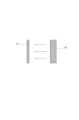
- FIG. 8 is an explanatory diagram showing how the light from the light source is irradiated onto the test specimen.
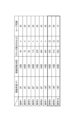
- FIG. 9 is an explanatory diagram showing the results of the deterioration test.
- FIG. 10 is a block diagram showing the hardware configuration of this embodiment.
- FIG. 1 is a side view showing the configuration of a degradation test device 100 according to an embodiment.
- FIG. 2 is a cross-sectional view taken from the A-A' direction shown in FIG. 1.
- the degradation test device 100 includes a housing 1 and a control device 2 arranged near the side of the housing 1.
- the housing 1 has a hollow rectangular parallelepiped shape and has an airtight structure inside. Legs 3 are provided at the bottom of the housing 1. The housing 1 is supported by the legs 3 and placed on a flat floor surface.
- a support 13 is installed inside the housing 1, connecting the center of the top plate 11 to the center of the bottom plate 12.
- An upper disk 14 and a lower disk 15 (fixed members) are connected to the support 13.
- a light source 16 is installed in the portion of the support 13 between the upper disk 14 and the lower disk 15.
- the support 13 can be rotated by the rotation mechanism 26 with the longitudinal direction as the rotation axis. That is, by controlling the rotation mechanism 26, the upper disk 14 and the lower disk 15 can be rotated around the support 13 (central axis).
- the rotation mechanism 26 is equipped with, for example, a stepping motor, and can rotate the upper disk 14 and the lower disk 15 and stop them at a predetermined angle. By rotating the lower disk 15 (fixed member), the rotation mechanism 26 controls the positioning of the multiple test specimens 21 in turn within the imaging range of the imaging unit 22 (details of which will be described later).
- the light source 16 irradiates light simulating sunlight in the surroundings (360° radial direction). That is, the light source 16 is installed in the center of the lower disk 15 (fixed member) and irradiates light to multiple test specimens 21.
- the light source 16 irradiates light including light in the ultraviolet region to the test specimens 21 present in the surroundings.
- the light source 16 may irradiate light in the visible region and infrared region in addition to ultraviolet light.
- the light source 16 may be an ultraviolet fluorescent lamp, a xenon lamp, a sunshine carbon lamp, or a metal halide lamp. Furthermore, each of the above lamps may be combined with a filter to bring the spectral radiation distribution of the emitted light closer to that of sunlight.
- the light source 16 may be one that performs tests conforming to "ISO 11341", "JIS K 5600-7-7", “JIS K 7350-2", etc.
- a number of support members 27 (10 in this example) are erected at equal intervals along the circumferential direction on the upper surface of the lower disk 15.
- a lower fixing device 18 (see Figure 1) is installed near the side of each support member 27, and an upper fixing device 17 that forms a pair with the lower fixing device 18 is installed above the lower fixing device 18.
- the upper fixing device 17 is connected to and supported by the upper end of the support member 27.
- Figure 3 is a perspective view showing the configuration of the support member 27 and the upper fixture 17, lower fixture 18, and test specimen 21 installed near its sides. As shown in Figure 3, the strip-shaped test specimen 21 is placed between the upper fixture 17 and lower fixture 18. In other words, each test specimen 21 is installed on the circumference of the circular lower disk 15 (fixing member).
- test specimen 21 The upper end of the test specimen 21 is connected to the upper fixture 17, and the lower end is connected to the lower fixture 18. In other words, the test specimen 21 can be attached and detached by manipulating the upper fixture 17 and the lower fixture 18.
- the bending mechanism 19 is installed at approximately the center of the support member 27 in the vertical direction.
- the bending mechanism 19 bends the support member 27 by a predetermined angle under the control of the control device 2. For example, the support member 27 is bent to ⁇ 30°, ⁇ 60°, ⁇ 90°, ⁇ 120°, or ⁇ 180°.
- Two bending jigs 20A, 20B are connected to the lower fixture 18, and the tip ends PA, PB of each bending jig 20A, 20B are cylindrical.
- the tip ends PA, PB of the two bending jigs 20A, 20B can clamp approximately the center of the test piece 21.
- the test body 21 can be bent. That is, as shown in FIG. 3, the center of the test body 21 is clamped between the tips PA and PB of the two bending jigs 20A and 20B. Therefore, when the support member 27 is bent by a predetermined angle, as shown in FIG. 4, the test body 21 connected to the upper fixture 17 is bent by the predetermined angle with the part clamped by the tips PA and PB as the fulcrum. That is, the bending mechanism 19 switches between extending and bending the test body 21.
- the lower fixture 18 is equipped with a moving mechanism 25.
- the moving mechanism 25 retracts the two bending jigs 20A, 20B individually under the control of the control device 2. Specifically, as shown in FIG. 5, the moving mechanism 25 can retract the bending jig 20B by tilting it downward. Although not shown in the figure, the moving mechanism 25 can also retract the bending jig 20A by tilting it downward in the same manner.
- the position where bending jigs 20A and 20B are tilted downward is referred to as the "retracted position,” and the position where bending jigs 20A and 20B clamp test piece 21 is referred to as the "operating position.”
- the bending jig 20B is prevented from becoming an obstacle when the imaging unit 22 (described in detail later) images the test piece 21.
- the movement mechanism 25 can move each bending jig 20A, 20B to either the operating position or the retracted position.
- the imaging unit 22 is installed at an appropriate position on the inner side of the housing 1. That is, the imaging unit 22 is installed around the lower disk 15 (fixed member).
- the imaging unit 22 is, for example, an optical camera or a CCD camera. A microscope may also be used as the imaging unit 22.
- the imaging unit 22 is installed at a position where it can capture an image of the vicinity of the center of the test piece 21. That is, the imaging unit 22 captures an image of the test piece 21.
- a humidity regulator 23 is provided on the top surface of the upper disk 14 to maintain the interior of the housing 1 at a predetermined humidity level.
- a temperature regulator 24 is provided on the inner side of the housing 1 to maintain the inside of the housing 1 at a predetermined temperature.
- FIG. 6 is a block diagram showing the configuration of the control device 2 and each device connected to the control device 2.
- the control device 2 includes a control unit 31, a determination unit 32, a display unit 33, and a storage unit 34.
- the control device 2 is connected to the light source 16, the imaging unit 22, the temperature regulator 24, the humidity regulator 23, the bending mechanism 19, the movement mechanism 25, and the rotation mechanism 26.
- the control unit 31 controls the turning on and off of the light source 16.
- the control unit 31 controls the imaging unit 22 to capture an image of the test specimen 21.
- the control unit 31 controls the temperature regulator 24 to maintain the temperature inside the housing 1 at a predetermined temperature.
- the control unit 31 controls the humidity regulator 23 to maintain the humidity inside the housing 1 at a predetermined humidity.
- the control unit 31 controls the bending mechanisms 19 provided for each of the 10 test specimens 21, thereby controlling the support members 27 corresponding to each test specimen 21 to bend by a predetermined angle.
- the bending angles of the 10 test specimens 21 are controlled to be 30°, 60°, 90°, 120°, 180°, -30°, -60°, -90°, -120°, and -180°, respectively.
- the bending mechanisms 19 are preferably configured to be capable of carrying out tests conforming to "JIS P8115", "JIS-K5600", "JIS C 3005", etc.
- the bending angle of each test body 21 can be set arbitrarily.
- the bending angles of all 10 test bodies 21 may be set to the same angle (e.g., 30°), or the 10 test bodies 21 may be divided into groups of 5 and the test bodies 21 in each group may be set to the same angle.
- the multiple test bodies 21 may be divided into test bodies to be bent at a first angle and test bodies to bent at a second angle, and the bending mechanism 19 may extend and bend each test body at the divided angle.
- all 10 test bodies 21 may be set to different bending angles.
- the control unit 31 controls the bending mechanisms 19 provided for each of the 10 test specimens 21, thereby controlling the number of times that the support members 27 corresponding to each test specimen 21 repeat bending and stretching (hereinafter referred to as the "number of bending and stretching N") to be a predetermined number.
- the number of bending and stretching of the 10 test specimens 21 is controlled to be 5, 10, 15, and 20 times.
- the number of times N each test specimen 21 is bent and stretched can be set arbitrarily.
- the number of times N each of the 10 test specimens 21 is bent and stretched may be set to the same (e.g., 10 times), or the 10 test specimens 21 may be divided into groups of 5 each, and the number of times N each of the test specimens 21 in each group may be set to the same (e.g., 10 times and 30 times).
- the multiple test specimens 21 are divided into test specimens that are repeatedly stretched and bent a first number of times, and test specimens that are repeatedly stretched and bent a second number of times, and the bending mechanism 19 stretches and bends each test specimen 21 the number of times N each of the groups is set to.
- the number of times N each of the 10 test specimens 21 may be set to different numbers.
- the control unit 31 controls the movement mechanism 25 to move the bending jig 20A to either the operating position or the retracted position described above.
- the control unit 31 controls the rotation mechanism 26 to rotate the support 13, which in turn rotates the upper disk 14 and the lower disk 15.
- the control unit 31 controls the support 13 to rotate in increments of 36°, for example, so that the ten test specimens 21 mounted on the lower disk 15 are positioned exactly within the imaging range of the imaging unit 22.
- the determination unit 32 determines the depth of the crack that occurs in the test specimen 21 as a percentage of the thickness of the test specimen 21. For example, the depth of the crack is determined as "crack depth 30%.”
- Well-known image processing techniques can be used for the process of analyzing the image, and detailed explanations will be omitted.
- the memory unit 34 stores the judgment result of the judgment unit 32.
- the display unit 33 is, for example, a display, and when the crack depth reaches or exceeds a predetermined value, the determination unit 32 displays information indicating an alarm on the display.
- This light is irradiated onto ten test specimens 21 placed around the light source 16.
- the movement mechanism 25 shown in FIG. 1 controls the bending jig 20A shown in FIG. 3 to be in a retracted position (a position moved downward). Therefore, the light irradiated from the light source 16 is irradiated almost uniformly onto each of the ten test specimens 21 without being blocked by the bending jig 20A.
- step S12 the movement mechanism 25 controls the bending jig 20A to move to the operating position after the time T1 has elapsed. As a result, as shown in FIG. 3, the center of the test piece 21 is clamped between the tips PA and PB of the two bending jigs 20A and 20B.
- step S13 the control unit 31 drives the bending mechanism 19 and controls it so that the test body 21 is bent to the desired angle ⁇ .
- the control unit 31 controls the 10 test bodies 21 to bend at angles of ⁇ 30°, ⁇ 60°, ⁇ 90°, ⁇ 120°, and ⁇ 180°, respectively.
- this bending and extension operation is repeated a predetermined number of bending and extension times N.
- step S14 the movement mechanism 25 moves the outer bending jig 20B from the operating position to the retracted position as shown in FIG. 5. As a result, the bending jig 20B moves outside the imaging range of the imaging unit 22, so that the center of the test piece 21 comes into the imaging range of the imaging unit 22 without interference from the bending jig 20B.
- step S15 the imaging unit 22 captures an image of the test specimen 21.
- step S16 the determination unit 32 analyzes the image of the test specimen 21 and measures the thickness of the test specimen 21 and the depth of any cracks that have occurred in the test specimen 21.
- step S17 the control unit 31 determines whether imaging has been completed for all 10 test specimens 21. If imaging has been completed for all (S17; YES), the process proceeds to step S19. If not (S17; NO), the process proceeds to step S18.
- step S18 the control unit 31 controls the rotation mechanism 26 to rotate the support 13 by 36° (an angle of 1/10 of the circumference). As a result, the next test piece 21 moves into the imaging range of the imaging unit 22. Then, the processes of steps S15 and S16 are repeated.
- step S19 the determination unit 32 determines whether or not there is a test specimen 21 whose crack depth has reached D% (e.g., 30%) of the total thickness based on the thickness and crack depth of each of the 10 test specimens 21. If there is (S19; YES), the process proceeds to step S21; if not (S19; NO), the process proceeds to step S20.
- D% e.g. 30%
- step S20 the control unit 31 determines whether the total time of the weather resistance test, i.e., the total time of light irradiation, has reached the time limit Tmax. If Tmax has been reached (S20; YES), the process proceeds to step S21; if not (S20; NO), the process returns to step S11.
- step S21 the control unit 31 displays on the display unit 33 a notification indicating that an abnormality has occurred in the test specimen 21.
- the operator can recognize that an abnormality such as a crack has occurred in the test specimen 21. Thereafter, this process ends.
- FIG. 9 shows the test results when a deterioration test was conducted with a constant light irradiation time and with the bending angle, number of bendings, and number of loops of the test specimen 21 set as shown in (Condition 1) to (Condition 10).
- the "number of loops" refers to the number of times the weather resistance test and bending test are repeated, that is, the number of times steps S11 to S20 (NO) shown in FIG. 7 are repeated.
- (Condition 1) shown in FIG. 9 indicates that the crack depth is 4% when the bending angle of the test specimen 21 is 30°, the number of bendings per loop is 10, and the number of loops is 30.
- test specimen 21 can be used outdoors for long periods of time if it is used so that the bending angle is within 90°.
- Such results cannot be easily predicted from a simple combination of a weather resistance test device and a bending test device that have been used conventionally.
- the degradation test device 100 it becomes possible to predict in a simple manner the range of environmental and mechanical conditions that the test specimen 21 can withstand.
- the degradation test device 100 includes a light source 16 that irradiates light onto a test specimen 21 made of a polymeric material, a bending mechanism 19 that switches between extending and bending the test specimen 21, an imaging unit 22 that images the test specimen 21, and a determination unit 32 that determines the degradation of the test specimen 21 based on the image captured by the imaging unit 22.
- the weather resistance test and bending test of the test specimen 21 can be performed in the same housing 1. This allows the weather resistance test and bending test to be performed simultaneously in a simple manner, making it possible to evaluate the combined deterioration caused by exposure to sunlight and bending.
- the degradation test is terminated when the depth of the cracks that occur in the test specimen 21 reaches a set value (e.g., 50%), making it possible to easily recognize the environmental conditions under which the test specimen 21 can be used and the state of the cracks that occur at that time.
- a set value e.g. 50%
- test specimens 21 are placed inside the housing 1, and a bending mechanism 19 is installed for each test specimen 21, so the bending angle ⁇ and number of bending and stretching times N of each test specimen 21 can be set to any value. It becomes possible to set various conditions to perform a deterioration test on the test specimens 21, and the rate of deterioration depending on the bending angle ⁇ can be evaluated.
- the multiple test specimens 21 are divided into test specimens that are bent at a first angle and test specimens that are bent at a second angle, and the bending mechanism 19 extends and bends each test specimen 21 at the divided angle, making it possible to set multiple bending angles and bending/extending times to perform degradation tests on the test specimens 21.
- the light source 16 emits light that mimics sunlight, making it possible to simulate a situation in which, for example, the sheath of an electric wire is exposed to sunlight, making it possible to carry out a more accurate deterioration test.
- the degradation test device 100 of this embodiment described above can be, for example, a general-purpose computer system equipped with a CPU (Central Processing Unit, processor) 901, memory 902, storage 903 (HDD: Hard Disk Drive, SSD: Solid State Drive), communication device 904, input device 905, and output device 906, as shown in FIG. 10.
- the memory 902 and storage 903 are storage devices.
- each function of the degradation test device 100 is realized by the CPU 901 executing a predetermined program loaded on the memory 902.
- the degradation test device 100 may be implemented in one computer, or in multiple computers.
- the degradation test device 100 may also be a virtual machine implemented in a computer.
- the program for the degradation test device 100 can be stored on a computer-readable recording medium such as a HDD, SSD, USB (Universal Serial Bus) memory, CD (Compact Disc), or DVD (Digital Versatile Disc), or can be distributed via a network.
- a computer-readable recording medium such as a HDD, SSD, USB (Universal Serial Bus) memory, CD (Compact Disc), or DVD (Digital Versatile Disc), or can be distributed via a network.
- the computer-readable recording medium is, for example, a non-transitory recording medium.
- REFERENCE SIGNS LIST 1 Housing 2 Control device 3 Legs 11 Top plate 12 Bottom plate 13 Support 14 Upper disk 15 Lower disk (fixing member) REFERENCE SIGNS LIST 16 Light source 17 Upper fixing tool 18 Lower fixing tool 19 Bending mechanism 20A, 20B Bending tool 21 Test piece 22 Imaging unit 23 Humidity regulator 24 Temperature regulator 25 Moving mechanism 26 Rotation mechanism 27 Support member 31 Control unit 32 Determination unit 33 Display unit 34 Memory unit 100 Deterioration test device
Landscapes
- Life Sciences & Earth Sciences (AREA)
- Biodiversity & Conservation Biology (AREA)
- Ecology (AREA)
- Environmental & Geological Engineering (AREA)
- Environmental Sciences (AREA)
- Physics & Mathematics (AREA)
- Health & Medical Sciences (AREA)
- Chemical & Material Sciences (AREA)
- Analytical Chemistry (AREA)
- Biochemistry (AREA)
- General Health & Medical Sciences (AREA)
- General Physics & Mathematics (AREA)
- Immunology (AREA)
- Pathology (AREA)
- Testing Resistance To Weather, Investigating Materials By Mechanical Methods (AREA)
Priority Applications (2)
| Application Number | Priority Date | Filing Date | Title |
|---|---|---|---|
| JP2024561073A JPWO2024116343A1 (https=) | 2022-11-30 | 2022-11-30 | |
| PCT/JP2022/044227 WO2024116343A1 (ja) | 2022-11-30 | 2022-11-30 | 劣化試験装置及び劣化試験方法 |
Applications Claiming Priority (1)
| Application Number | Priority Date | Filing Date | Title |
|---|---|---|---|
| PCT/JP2022/044227 WO2024116343A1 (ja) | 2022-11-30 | 2022-11-30 | 劣化試験装置及び劣化試験方法 |
Publications (1)
| Publication Number | Publication Date |
|---|---|
| WO2024116343A1 true WO2024116343A1 (ja) | 2024-06-06 |
Family
ID=91323133
Family Applications (1)
| Application Number | Title | Priority Date | Filing Date |
|---|---|---|---|
| PCT/JP2022/044227 Ceased WO2024116343A1 (ja) | 2022-11-30 | 2022-11-30 | 劣化試験装置及び劣化試験方法 |
Country Status (2)
| Country | Link |
|---|---|
| JP (1) | JPWO2024116343A1 (https=) |
| WO (1) | WO2024116343A1 (https=) |
Citations (8)
| Publication number | Priority date | Publication date | Assignee | Title |
|---|---|---|---|---|
| JPH0431739A (ja) * | 1990-05-28 | 1992-02-03 | Suga Shikenki Kk | 疲労耐候試験方法 |
| JP2018159553A (ja) * | 2017-03-22 | 2018-10-11 | スガ試験機株式会社 | 耐候性試験機用試料保持ボックスおよび該ボックスを備えた耐候性試験機 |
| CN209707331U (zh) * | 2019-03-06 | 2019-11-29 | 湖北硕星油墨科技有限公司 | 一种油墨紫外加速老化试验箱 |
| JP2019211287A (ja) * | 2018-06-01 | 2019-12-12 | 岩崎電気株式会社 | 耐候性試験装置 |
| JP2020118465A (ja) * | 2019-01-18 | 2020-08-06 | 横浜ゴム株式会社 | 加硫ゴム材料のオゾン劣化評価システム |
| CN212568393U (zh) * | 2020-04-15 | 2021-02-19 | 上海驰纺材料科技有限公司 | 一种光致变色材料耐紫外疲劳性测试装置 |
| CN113237776A (zh) * | 2021-05-31 | 2021-08-10 | 青岛中和聚氨酯材料有限公司 | 一种聚氨酯高温光照形变检测装置及其检测方法 |
| WO2022230083A1 (ja) * | 2021-04-28 | 2022-11-03 | 日本電信電話株式会社 | 試験装置および方法 |
-
2022
- 2022-11-30 WO PCT/JP2022/044227 patent/WO2024116343A1/ja not_active Ceased
- 2022-11-30 JP JP2024561073A patent/JPWO2024116343A1/ja active Pending
Patent Citations (8)
| Publication number | Priority date | Publication date | Assignee | Title |
|---|---|---|---|---|
| JPH0431739A (ja) * | 1990-05-28 | 1992-02-03 | Suga Shikenki Kk | 疲労耐候試験方法 |
| JP2018159553A (ja) * | 2017-03-22 | 2018-10-11 | スガ試験機株式会社 | 耐候性試験機用試料保持ボックスおよび該ボックスを備えた耐候性試験機 |
| JP2019211287A (ja) * | 2018-06-01 | 2019-12-12 | 岩崎電気株式会社 | 耐候性試験装置 |
| JP2020118465A (ja) * | 2019-01-18 | 2020-08-06 | 横浜ゴム株式会社 | 加硫ゴム材料のオゾン劣化評価システム |
| CN209707331U (zh) * | 2019-03-06 | 2019-11-29 | 湖北硕星油墨科技有限公司 | 一种油墨紫外加速老化试验箱 |
| CN212568393U (zh) * | 2020-04-15 | 2021-02-19 | 上海驰纺材料科技有限公司 | 一种光致变色材料耐紫外疲劳性测试装置 |
| WO2022230083A1 (ja) * | 2021-04-28 | 2022-11-03 | 日本電信電話株式会社 | 試験装置および方法 |
| CN113237776A (zh) * | 2021-05-31 | 2021-08-10 | 青岛中和聚氨酯材料有限公司 | 一种聚氨酯高温光照形变检测装置及其检测方法 |
Also Published As
| Publication number | Publication date |
|---|---|
| JPWO2024116343A1 (https=) | 2024-06-06 |
Similar Documents
| Publication | Publication Date | Title |
|---|---|---|
| CN114207417B (zh) | 用于反射样本的宏观检查的系统、方法和设备 | |
| JP7454265B2 (ja) | マクロ検査システム、装置および方法 | |
| US10054527B2 (en) | Method and system for bending test of flexible screen | |
| TWI669485B (zh) | 可調整取像組合之自動光學檢測設備及取像組合調整方法 | |
| CN106802273B (zh) | 曝光加速的户外试验设备 | |
| JP7022111B2 (ja) | 半導体製造歩留まりを向上させるための方法 | |
| JP2013109077A5 (https=) | ||
| WO2024116343A1 (ja) | 劣化試験装置及び劣化試験方法 | |
| KR20170068361A (ko) | 카메라 모듈 검사 장치 및 이를 이용한 카메라 모듈 검사 방법 | |
| TWI390648B (zh) | 樣本檢查裝置 | |
| WO2024134874A1 (ja) | 劣化促進方法、及び、劣化促進装置 | |
| CN113203996B (zh) | 保险杠对毫米波雷达性能影响的测试方法及其装置与系统 | |
| CN113793338B (zh) | 一种带孔金属件缺陷检测方法、系统、装置及存储介质 | |
| CN207439958U (zh) | 产品表面缺陷检测装置 | |
| JP6838738B2 (ja) | 耐候性試験機用試料保持ボックスおよび該ボックスを備えた耐候性試験機 | |
| US10198827B2 (en) | Inspection method and system and a method of inspecting a semiconductor device using the same | |
| CN113340924A (zh) | 检验系统及检验系统的控制方法 | |
| KR20210107530A (ko) | 반사계, 분광 광도계, 또는 엘립소미터 시스템을 사용하는 샘플 맵핑에 적용되는 세타-세타 샘플 포지셔닝 스테이지 | |
| US7092081B2 (en) | Apparatus for measuring optoelectric properties of OLED and the measurement method thereof | |
| CN206670893U (zh) | 一种用于镜片生产的mtf检测装置 | |
| TWI586948B (zh) | 用於判定最小光束點之大小及位置的系統及方法 | |
| CN118067734A (zh) | 半导体器件的缺陷表征方法、装置、电子设备及存储介质 | |
| CN116244318A (zh) | 一种设备巡检方法、装置及电子设备和存储介质 | |
| US8780341B2 (en) | Inspecting system for lens module | |
| CN116087554B (zh) | 风场测试方法和风场测试装置 |
Legal Events
| Date | Code | Title | Description |
|---|---|---|---|
| 121 | Ep: the epo has been informed by wipo that ep was designated in this application |
Ref document number: 22967176 Country of ref document: EP Kind code of ref document: A1 |
|
| WWE | Wipo information: entry into national phase |
Ref document number: 2024561073 Country of ref document: JP |
|
| NENP | Non-entry into the national phase |
Ref country code: DE |
|
| 122 | Ep: pct application non-entry in european phase |
Ref document number: 22967176 Country of ref document: EP Kind code of ref document: A1 |