WO2024116341A1 - 工作機械の制御装置 - Google Patents
工作機械の制御装置 Download PDFInfo
- Publication number
- WO2024116341A1 WO2024116341A1 PCT/JP2022/044222 JP2022044222W WO2024116341A1 WO 2024116341 A1 WO2024116341 A1 WO 2024116341A1 JP 2022044222 W JP2022044222 W JP 2022044222W WO 2024116341 A1 WO2024116341 A1 WO 2024116341A1
- Authority
- WO
- WIPO (PCT)
- Prior art keywords
- cutting
- machining
- setting
- amount
- control device
- Prior art date
- Legal status (The legal status is an assumption and is not a legal conclusion. Google has not performed a legal analysis and makes no representation as to the accuracy of the status listed.)
- Ceased
Links
Images






Classifications
-
- G—PHYSICS
- G05—CONTROLLING; REGULATING
- G05B—CONTROL OR REGULATING SYSTEMS IN GENERAL; FUNCTIONAL ELEMENTS OF SUCH SYSTEMS; MONITORING OR TESTING ARRANGEMENTS FOR SUCH SYSTEMS OR ELEMENTS
- G05B19/00—Program-control systems
- G05B19/02—Program-control systems electric
- G05B19/18—Numerical control [NC], i.e. automatically operating machines, in particular machine tools, e.g. in a manufacturing environment, so as to execute positioning, movement or co-ordinated operations by means of program data in numerical form
- G05B19/4093—Numerical control [NC], i.e. automatically operating machines, in particular machine tools, e.g. in a manufacturing environment, so as to execute positioning, movement or co-ordinated operations by means of program data in numerical form characterised by part programming, e.g. entry of geometrical information as taken from a technical drawing, combining this with machining and material information to obtain control information, named part program, for the NC machine
-
- G—PHYSICS
- G05—CONTROLLING; REGULATING
- G05B—CONTROL OR REGULATING SYSTEMS IN GENERAL; FUNCTIONAL ELEMENTS OF SUCH SYSTEMS; MONITORING OR TESTING ARRANGEMENTS FOR SUCH SYSTEMS OR ELEMENTS
- G05B19/00—Program-control systems
- G05B19/02—Program-control systems electric
- G05B19/18—Numerical control [NC], i.e. automatically operating machines, in particular machine tools, e.g. in a manufacturing environment, so as to execute positioning, movement or co-ordinated operations by means of program data in numerical form
- G05B19/182—Numerical control [NC], i.e. automatically operating machines, in particular machine tools, e.g. in a manufacturing environment, so as to execute positioning, movement or co-ordinated operations by means of program data in numerical form characterised by the machine tool function, e.g. thread cutting, cam making, tool direction control
-
- G—PHYSICS
- G05—CONTROLLING; REGULATING
- G05B—CONTROL OR REGULATING SYSTEMS IN GENERAL; FUNCTIONAL ELEMENTS OF SUCH SYSTEMS; MONITORING OR TESTING ARRANGEMENTS FOR SUCH SYSTEMS OR ELEMENTS
- G05B2219/00—Program-control systems
- G05B2219/30—Nc systems
- G05B2219/45—Nc applications
- G05B2219/45215—Thread cutting
Definitions
- This disclosure relates to a control device for a machine tool.
- the tool path which is the trajectory of the tool, is set to overlap partially with the previous tool path, generating an air cut in which the tool separates from the workpiece surface, shredding the chips.
- swing thread cutting due to the machining principle of using oscillation, increases the number of machining operations and increases the cycle time. Also, in swing thread cutting, it is possible to cool the machining heat of the cutting tool during air cutting, so there was the possibility of shortening the cycle time by increasing the amount of cutting per operation, but this was not utilized. Alternatively, in swing thread cutting, in order to reduce the load on the cutting tool, it is sometimes preferable to reduce the amount of cutting by making the cutting depth smaller compared to normal thread cutting that does not involve oscillation.
- This disclosure has been made in consideration of the above-mentioned problems, and aims to provide a technology in a control device of a machine tool that controls thread cutting, which automatically sets the cutting depth to achieve thread cutting according to the operator's request.
- the present disclosure relates to a control device for a machine tool that performs thread cutting on a workpiece using a cutting tool
- the control device for the machine tool including a machining condition acquisition unit that acquires machining conditions for the thread cutting, a machining judgment unit that judges the type of machining from the machining conditions, a cutting depth rule setting unit that determines a setting rule that is a method for setting the cutting depth for the thread cutting based on the judgment result of the machining judgment unit, and a cutting depth determination unit that determines the cutting depth during machining based on the machining conditions and the setting rule.
- This disclosure provides a technology that automatically sets the cutting depth to achieve thread cutting according to the operator's needs in a machine tool control device that controls thread cutting.
- FIG. 1 is a functional block diagram of a control device for a machine tool according to a first embodiment of the present invention.
- FIG. FIG. 11 is a diagram showing an example of a machining program when oscillating machining is not performed in the first embodiment.
- 5 is a graph showing the positional relationship between a workpiece and a cutting tool when oscillation machining is not performed in the first embodiment.
- FIG. 11 is a diagram showing an example of a machining program for performing oscillating machining in the first embodiment.
- 11 is a graph showing the positional relationship between a workpiece and a cutting tool when a first setting rule is applied and a cutting depth is changed.
- 11 is a graph showing the positional relationship between a workpiece and a cutting tool during swing machining to which a first setting rule is applied.
- FIG. 11 is a functional block diagram of a control device for a machine tool according to a third embodiment.
- FIG. 13 is a functional block diagram of a control device for a machine tool according to a fourth embodiment.
- FIG. 1 is a functional block diagram of a control device 1 for a machine tool according to a first embodiment of the present invention.
- the control device 1 for a machine tool shown in FIG. 1 is for performing thread cutting by a cutting tool that oscillates in a radial direction relative to a workpiece.
- FIG. 1 shows only a motor 3 that drives one feed axis.
- the shape of the workpiece is not limited in the cutting process according to this embodiment.
- the present invention is applicable even when the workpiece has a tapered portion or a circular arc portion on the machining surface, which requires multiple feed axes (Z axis and X axis), or when the workpiece is columnar or cylindrical and only one specific feed axis (Z axis) is sufficient.
- the machine tool control device 1 of this embodiment is configured, for example, using a computer equipped with memories such as a ROM (read only memory) and a RAM (random access memory), a CPU (control processing unit), and a communication control unit, all connected to each other via a bus.
- memories such as a ROM (read only memory) and a RAM (random access memory), a CPU (control processing unit), and a communication control unit, all connected to each other via a bus.
- the functions and operations of each functional unit described below are achieved by the cooperation of the CPU, memory, and control programs stored in the memory mounted on the computer.
- the machine tool control device 1 may also be configured with a CNC (Computer Numerical Controller) or a PLC (Programmable Logic Controller), or may be connected to a higher-level computer that outputs machining conditions such as rotation speed in addition to machining programs.
- CNC Computer Numerical Controller
- PLC Programmable Logic Controller
- the control device 1 of the machine tool includes a machining condition acquisition unit 11, a machining judgment unit 12, a cutting depth rule setting unit 13, a cutting depth determination unit 20, a machining control unit 21, a memory unit 14, an input unit 15, and a display unit 16.
- the machining condition acquisition unit 11 acquires machining conditions and oscillation conditions for oscillating the workpiece.
- the machining conditions and oscillation conditions acquired by the machining condition acquisition unit 11 may be, for example, those stored in the memory unit 14, or may be those output from an external computer.
- the machining conditions include information about the shape of the thread and cutting conditions for the workpiece.
- information about the shape of the thread includes the thread lead (mm), thread diameter (mm), and thread angle (°).
- Cutting conditions for the workpiece include the spindle rotation speed S (1/min), finishing allowance (mm), number of finishing passes (times), and cutting position (mm).
- the cutting position is a reference position such as one end position (for example, the lower end position) or the other end position (upper end position) in the oscillation direction, and is not limited to a particular position.
- the cutting position may be information that can identify the cutting position, such as the cutting area. In this way, the cutting amount may be a length or area, or information that identifies a position.
- the oscillation conditions include information related to the number of oscillations in the radial direction of the workpiece and information related to the oscillation amplitude in the radial direction of the workpiece.
- Information related to the number of oscillations in the radial direction of the workpiece includes the oscillation frequency multiplication factor I (times), which indicates the oscillation frequency per one rotation of the spindle.
- Information related to the oscillation amplitude in the radial direction of the workpiece relative to the cutting tool and workpiece includes the oscillation amplitude multiplication factor K (times), which indicates the magnitude of the oscillation amplitude relative to the amount of cutting depth in the radial direction of the workpiece in thread cutting.
- the machining determination unit 12 determines the type of machining to be performed based on the machining conditions acquired by the machining condition acquisition unit 11. In the first embodiment, the machining determination unit 12 determines whether the machining to be performed based on the machining conditions is thread cutting with oscillation or thread cutting without oscillation.
- the cutting depth amount rule setting unit 13 sets setting rules for determining the cutting depth amount based on the judgment result of the machining judgment unit 12.
- the setting rules are set in advance to correspond to the type of machining judged by the machining judgment unit 12, for example.
- the setting rules may be stored in the memory unit 14, or may be output from an external computer.
- the specified set cutting depth is not changed in normal thread cutting without oscillation, but the set cutting depth is changed in thread cutting with oscillation.
- the setting rules will be described later.
- the cutting depth determination unit 20 determines the cutting depth during actual machining based on the set cutting depth included in the machining conditions and the setting rules set in the cutting depth rule setting unit 13.
- the machining control unit 21 generates an operation command based on the cutting depth determined by the cutting depth determination unit 20, and performs operation control based on the operation command.
- the motor 3 and other components are driven by the operation control, the workpiece and cutting tool are moved, and the thread cutting process is performed.
- the memory unit 14 stores various information for controlling and machining the machine tool.
- the memory unit 14 stores machining conditions and oscillation conditions.
- the machining conditions and oscillation conditions are, for example, those input by an operator into a machining program or those specified as machine tool parameters.
- the memory unit 14 may be configured to be located outside the control device 1 instead of inside it.
- the input unit 15 inputs information related to processing in response to an operator's input operation on an input means (not shown), such as a keyboard or a touch panel.
- the information related to processing input by the input unit 15 is stored in the memory unit 14 or the like, or input to each part of the control device 1.
- the display unit 16 displays various information related to the machine tool, the control device 1, and processing.
- the display unit 16 is, for example, configured by a display.
- FIG. 2 is a diagram showing an example of a machining program when oscillating machining is not performed in the first embodiment.
- the machining program shown in FIG. 2 is set, for example, by an operator.
- G76 in Figure 2 is a command for one block in the machining program, and is a code that generates movement blocks for multiple thread cutting operations.
- Q is a code that indicates the first cutting depth
- P is a code that indicates the height of the thread
- R is a code that indicates the angle of the thread.
- G76 X9.0 Z10.0 F2.0” and “Q10.0 R60.0" in the machining program are obtained as the thread cutting conditions (thread lead, thread angle, set cutting depth).
- FIG. 3 is a graph showing the positional relationship between the workpiece and the cutting tool T when no oscillating machining is performed in the first embodiment.
- the operation command shown in the graph in FIG. 3 is generated.
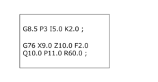
- Figure 4 is a diagram showing an example of a machining program when performing oscillation machining in the first embodiment.
- the machining program shown in Figure 4 is set, for example, by an operator.
- the machining conditions indicate that oscillation is to be performed, as in the machining program shown in FIG. 4, a process is executed to set a new cutting depth based on preset setting rules.
- the setting rules are preset in the control device 1 based on priorities. Below, a first setting rule and a second setting rule, which have different priorities, are described.
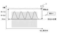
- Figure 5 is a graph showing the positional relationship between the workpiece and the cutting tool T when the first setting rule is applied and the cutting depth is changed.
- Figure 6 is a graph showing the positional relationship between the workpiece and the cutting tool T during oscillating machining when the first setting rule is applied.
- the first setting rule prioritizes reducing the number of machining operations in order to shorten the cycle time, and in the case of thread cutting with oscillation, it specifies the cutting depth so that the number of operations is smaller than in normal thread cutting.
- the set cut-in positions are obtained from the machining program, indicating that the thread position is 11.0 mm, the set cut-in position is 10.0 mm, and the cut-in position as the finishing position is 9.0 mm.
- the cutting depth determination unit 20 obtains the number of cutting positions to cancel and the cancellation method from the setting rules set by the cutting depth rule setting unit 13.
- a rule has been set to cancel the even-numbered number of cuttings.
- the cutting depth determination unit 20 cancels the even-numbered cutting positions counting from the thread position in accordance with the setting rules.
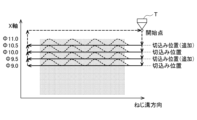
- Figure 7 is a graph showing the positional relationship between the workpiece and the cutting tool T when the second setting rule is applied and the cutting depth is changed.
- Figure 8 is a graph showing the positional relationship between the workpiece and the cutting tool T during oscillating machining when the second setting rule is applied.
- the second setting rule prioritizes reducing the load on the workpiece and cutting tool T per machining cycle, and in the case of thread cutting with oscillation, specifies the amount of cut so that the number of executions is greater than in normal thread cutting.
- the set cut-in positions are obtained from the machining program, indicating that the thread position is 11.0 mm, the set cut-in position is 10.0 mm, and the cut-in position as the finishing position is 9.0 mm.
- the amount of cut is added based on the position of the set amount of cut, but this is not limiting and the amount of cut may be set according to a specified index.
- the position of the set amount of cut may be changed to add a cut position so that the maximum amount of cutting at each cut is constant.
- the second setting rule may add a cutting position for each cutting amount according to a predetermined maximum cutting amount set for each cutting.
- a predetermined maximum cutting area is preset in the control device 1 instead of a predetermined cutting amount.
- the maximum cutting area here is the cutting area when the cutting position during oscillation reaches the deepest position.
- the setting rule calculates the predetermined cutting amount that results in the maximum cutting area using a known calculation method, and adds a cutting position between each cutting position.
- Figure 9 is a flowchart showing an example of the thread cutting command generation process by the control device of a machine tool.
- the machining condition acquisition unit 11 acquires the thread cutting conditions for performing the thread cutting (step S10).
- the thread cutting conditions are, for example, machining conditions including the cutting depth described above and swing conditions.
- the thread cutting conditions are acquired from the machining program stored in the memory unit 14 and parameters set in the machine tool.
- the machining determination unit 12 determines whether or not the machining mode is a specific machining mode (thread cutting with oscillation) based on the machining conditions (step S11). In the first embodiment, the machining determination unit 12 advances the process to step S12 if the machining mode is thread cutting with oscillation (step S11; Yes), and advances the process to step S20 if the machining mode is thread cutting without oscillation (step S11; No).
- step S12 the cutting depth rule setting unit 13 sets the setting rule based on the determination result of the process determination unit 12, and the cutting depth determination unit 20 newly specifies the cutting depth for the thread cutting process involving oscillation based on the set cutting depth and the setting rule (see Figures 5 and 7).
- step S12 the machining control unit 21 generates a thread cutting command for oscillating machining based on the cutting depth determined by the cutting depth determination unit 20 (step S13), and thread cutting with oscillation is performed (step S14).
- step S20 the cutting depth rule setting unit 13 sets the setting rule based on the determination result of the process determination unit 12, and the cutting depth determination unit 20 specifies the set cutting depth as the cutting depth for normal processing without oscillation.
- the machining control unit 21 generates a thread cutting command for normal machining to perform thread cutting without oscillation based on the cutting depth determined by the cutting depth determination unit 20 (step S21), and normal thread cutting without oscillation is performed (step S22).
- the control device 1 for the machine tool of the first embodiment which performs thread cutting on a workpiece using the cutting tool T described above, provides the following effects.
- the control device 1 of the machine tool includes a machining condition acquisition unit 11 that acquires the machining conditions for thread cutting, a machining judgment unit 12 that judges the type of machining from the machining conditions, a cutting amount rule setting unit 13 that determines a setting rule for setting the cutting amount for thread cutting based on the judgment result of the machining judgment unit 12, and a cutting amount determination unit 20 that determines the cutting amount during machining based on the machining conditions and the setting rule.
- the cutting amount that reflects the operator's priorities is automatically set, and thread cutting suitable for the actual situation is performed.
- the machining judgment unit 12 of this embodiment judges whether the machining involves swing cutting or not from the machining conditions, and the cutting depth rule setting unit 13 determines the setting rule depending on whether swing cutting is performed or not. This makes it possible to distinguish between swing cutting, which is greatly affected by the cycle time and the cutting tool T, and to perform thread cutting based on a cutting depth suitable for swinging thread cutting.
- the machining condition acquisition unit 11 of this embodiment acquires a preset set cutting depth
- the cutting depth determination unit 20 determines the cutting depth during machining based on the set cutting depth and the setting rules. As a result, even if the cutting depth is preset, it is automatically adjusted to reflect the operator's priorities, making it easy to achieve thread cutting with high productivity and safety.
- the cutting depth amount rule setting unit 13 of this embodiment sets a setting rule for adding a cutting position between the multiple cutting positions acquired by the machining condition acquisition unit 11 from the machining conditions when it is determined that oscillation is to be performed, and the cutting depth amount determination unit 20 sets a cutting depth amount according to the set cutting depth amount or the maximum cutting amount based on the setting rule so that the cutting depth interval or the maximum cutting amount in a cutting is constant.
- the cutting depth amount rule setting unit 13 of this embodiment determines a setting rule for canceling at least one of the multiple cutting positions indicated by the set cutting depth amount. This automatically sets an operation command that prioritizes reducing the number of machining operations in order to shorten the cycle time, making it easy to achieve machining that meets the operator's requirements.
- control device 1 for a machine tool according to the first embodiment, but the configuration is not limited to the above embodiment.
- the setting rules are not limited to the contents described in the above embodiment, and the method for setting the cutting depth amount can be changed as appropriate depending on various conditions. Below, an embodiment that differs from the above embodiment is described.
- control device 1 Next, a control device 1 according to a second embodiment will be described.
- the basic configuration of the control device 1 according to the second embodiment is the same as the configuration shown in FIG.
- the cutting depth per cut is preset in the control device 1 rather than in the machining program.
- the cutting depth is stored in the memory unit 14 as a parameter set in the control device 1 of the machine tool.
- the predetermined cutting depth is set to 0.7 mm.
- the machining condition acquisition unit 11 acquires information indicating the cutting position from the machining conditions. For example, the thread position of 11.0 mm and the finishing position (target position) of 9.0 mm are acquired by the machining condition acquisition unit 11 as information indicating the cutting position.
- control device 1 when the processing conditions indicate that oscillation is to be performed, the control device 1 also executes a process to set a new cutting depth based on preset setting rules.
- FIG. 10 is a graph showing the positional relationship between the workpiece and the cutting tool T when the cutting depth is set by applying the setting rules of the second embodiment.
- the setting rules specify the cutting depth based on the thread position, which is the cutting depth position obtained from the machining conditions, the finishing position, and the specified cutting depth.
- the cutting depth for the swing process is specified by subtracting the specified cutting depth from the thread position 11.0 mm to the finishing position (target position) 9.0 mm.
- 10.3 mm which is obtained by subtracting the specified cutting depth of 0.7 from the thread position 11.0 mm
- 9.6 mm which is obtained by subtracting the specified cutting depth of 0.7 from 10.3 mm
- Subtracting the specified cutting depth of 0.7 from 9.6 mm results in 8.9, which exceeds the finishing position (target position) 9.0 mm, so the finishing position 9.0 mm is specified as the cutting depth for the third thread cutting process.
- thread cutting with swing and thread cutting without swing are performed for the specified cutting depths of 10.3 mm, 9.6 mm, and 9.0 mm.
- the cutting depth is specified based on a predetermined cutting depth, but the method is not limited to this, and the cutting depth can be determined according to a predetermined index.
- a predetermined maximum cutting area is preset in the control device 1.
- the maximum cutting area here is the cutting area when the cutting position during oscillation reaches the deepest position.
- the setting rule is to calculate the predetermined cutting depth that results in the maximum cutting area using a known calculation method.
- the method of specifying the cutting depth for oscillation processing is the same as the above-mentioned process. In this example, thread cutting with oscillation and thread cutting without oscillation are performed for the specified cutting depths of 10.3 mm, 9.6 mm, and 9.0 mm.
- the control device 1 for the machine tool of the second embodiment which performs thread cutting on a workpiece using the cutting tool T described above, provides the following effects.
- a setting rule is determined for setting the amount of cutting for each of a predetermined amount of cutting or an amount of cutting corresponding to a predetermined maximum cutting area.
- Fig. 11 is a functional block diagram of a control device 1a for a machine tool according to the third embodiment.
- the third embodiment is different from the above-mentioned embodiments in that the control device 1a includes a sensor 30 for measuring the temperatures of a cutting tool T for thread cutting, a drive motor, etc., but the other configurations are the same.
- the control device 1a of the third embodiment is set with a setting rule similar to the first setting rule of the first embodiment.
- the sensor 30 detects the current machining state (temperature) at the time when the cutting tool T is positioned at the start point.
- the cutting depth determination unit 20a of the third embodiment if the detection result of the sensor 30 indicates that there is room for machining, such as the temperature being sufficiently low, the cutting depth position to be machined from the next time onwards is cancelled. For example, if the temperature is lower than a specified value, a process is executed to cancel one cutting depth position. In this way, the setting rule may be changed according to the machining state.
- Fig. 12 is a functional block diagram of a control device 1b for a machine tool according to the fourth embodiment.
- the fourth embodiment is different from the above-mentioned embodiments in that the control device 1b includes an upper limit value acquisition unit 31, but the other configurations are the same.
- the upper limit value acquisition unit 31 acquires an upper limit value related to cutting.
- the upper limit value may be, for example, an upper limit value for the cutting depth amount, an upper limit value for the cutting amount, or an allowable load during cutting.
- the upper limit value is set taking into consideration the instantaneous maximum value when performing oscillation.
- the upper limit value is stored in the memory unit 14 as a machining program or a parameter of the control device 1 of the machine tool.
- the upper limit value may also be stored in an external storage device.
- the cutting depth determination unit 20b of the fourth embodiment determines the cutting depth for the actual thread cutting process by reflecting the upper limit value acquired by the upper limit value acquisition unit 31. That is, if the result of following the setting rules exceeds the upper limit value of any of the cutting depth amount, cutting amount, or allowable load during cutting, a process is executed to correct the cutting depth amount to the upper limit value or below the upper limit value.
- a setting rule may be set to set the cutting depth so that cutting is performed at the upper limit value of any of the cutting depth amount, cutting amount, or allowable load during cutting for each cutting.
- the control device 1b of the fourth embodiment of the machine tool which performs thread cutting on a workpiece using the cutting tool T described above, provides the following effects.
- the control device 1b of this embodiment further includes an upper limit value acquisition unit 31 that acquires an upper limit value related to cutting, and the cutting depth determination unit 20b determines the cutting depth reflecting the upper limit value in addition to the machining conditions and setting rules.
- machining judged by the machining judgement unit 12 is thread cutting with oscillation and thread cutting without oscillation, but this is not limited to this configuration.
- a configuration may be used in which ultrasonic cutting is judged as a specific function.
- a configuration may be used in which machining using a specific tool with excellent wear resistance is judged, and in the case of such machining, setting rules that take wear resistance into consideration are applied.
- a command is automatically generated to alternately repeat thread cutting with and without oscillation, but this is not limited to this.
- a configuration may be adopted in which thread cutting with oscillation is performed multiple times, followed by thread cutting without oscillation at least once.
- processing control is performed by adjusting the oscillation conditions so that the peaks and valleys of successive thread cutting with oscillation overlap.
- the processing control unit 21 can overlap the peaks and valleys in successive thread cutting with oscillation by performing processing to shift the phase of the oscillation conditions by 180 degrees.
- the machining determination unit (12) determines whether the machining is to be performed with or without swing cutting based on the machining conditions
- the cutting depth rule setting unit (13) determines the setting rule depending on whether or not swinging is performed.
- the processing condition acquisition unit (11) acquires a preset cutting depth
- the cutting depth determination unit (20, 20a, 20b) determines the cutting depth during machining based on the set cutting depth and the setting rule.
- the cutting amount rule setting unit (13) sets a setting rule for adding a cutting position between the multiple cutting positions acquired from the machining conditions by the machining condition acquisition unit (11) when it is determined that a swing motion is to be performed
- the cutting depth determination unit (20, 20a, 20b) sets a cutting depth corresponding to a predetermined index based on the setting rule so that the predetermined index becomes constant.
- a setting rule is determined for canceling at least one of the plurality of cutting positions indicated by the set cutting amount.
Landscapes
- Engineering & Computer Science (AREA)
- Physics & Mathematics (AREA)
- Human Computer Interaction (AREA)
- Manufacturing & Machinery (AREA)
- General Physics & Mathematics (AREA)
- Automation & Control Theory (AREA)
- Geometry (AREA)
- Numerical Control (AREA)
Priority Applications (4)
| Application Number | Priority Date | Filing Date | Title |
|---|---|---|---|
| JP2024561071A JPWO2024116341A1 (https=) | 2022-11-30 | 2022-11-30 | |
| PCT/JP2022/044222 WO2024116341A1 (ja) | 2022-11-30 | 2022-11-30 | 工作機械の制御装置 |
| CN202280102042.9A CN120266068A (zh) | 2022-11-30 | 2022-11-30 | 机床的控制装置 |
| DE112022007801.4T DE112022007801T5 (de) | 2022-11-30 | 2022-11-30 | Maschinenwerkzeug-Steuervorrichtung |
Applications Claiming Priority (1)
| Application Number | Priority Date | Filing Date | Title |
|---|---|---|---|
| PCT/JP2022/044222 WO2024116341A1 (ja) | 2022-11-30 | 2022-11-30 | 工作機械の制御装置 |
Publications (1)
| Publication Number | Publication Date |
|---|---|
| WO2024116341A1 true WO2024116341A1 (ja) | 2024-06-06 |
Family
ID=91323129
Family Applications (1)
| Application Number | Title | Priority Date | Filing Date |
|---|---|---|---|
| PCT/JP2022/044222 Ceased WO2024116341A1 (ja) | 2022-11-30 | 2022-11-30 | 工作機械の制御装置 |
Country Status (4)
| Country | Link |
|---|---|
| JP (1) | JPWO2024116341A1 (https=) |
| CN (1) | CN120266068A (https=) |
| DE (1) | DE112022007801T5 (https=) |
| WO (1) | WO2024116341A1 (https=) |
Citations (5)
| Publication number | Priority date | Publication date | Assignee | Title |
|---|---|---|---|---|
| WO2016067372A1 (ja) * | 2014-10-28 | 2016-05-06 | 三菱電機株式会社 | 数値制御装置 |
| JP2019185355A (ja) * | 2018-04-09 | 2019-10-24 | ファナック株式会社 | 工作機械の制御装置 |
| JP2021060690A (ja) * | 2019-10-03 | 2021-04-15 | ファナック株式会社 | 工作機械の制御装置 |
| WO2021153482A1 (ja) * | 2020-01-27 | 2021-08-05 | ファナック株式会社 | 工作機械の制御装置 |
| WO2021153483A1 (ja) * | 2020-01-28 | 2021-08-05 | ファナック株式会社 | 工作機械の制御装置 |
-
2022
- 2022-11-30 WO PCT/JP2022/044222 patent/WO2024116341A1/ja not_active Ceased
- 2022-11-30 JP JP2024561071A patent/JPWO2024116341A1/ja active Pending
- 2022-11-30 DE DE112022007801.4T patent/DE112022007801T5/de active Pending
- 2022-11-30 CN CN202280102042.9A patent/CN120266068A/zh active Pending
Patent Citations (5)
| Publication number | Priority date | Publication date | Assignee | Title |
|---|---|---|---|---|
| WO2016067372A1 (ja) * | 2014-10-28 | 2016-05-06 | 三菱電機株式会社 | 数値制御装置 |
| JP2019185355A (ja) * | 2018-04-09 | 2019-10-24 | ファナック株式会社 | 工作機械の制御装置 |
| JP2021060690A (ja) * | 2019-10-03 | 2021-04-15 | ファナック株式会社 | 工作機械の制御装置 |
| WO2021153482A1 (ja) * | 2020-01-27 | 2021-08-05 | ファナック株式会社 | 工作機械の制御装置 |
| WO2021153483A1 (ja) * | 2020-01-28 | 2021-08-05 | ファナック株式会社 | 工作機械の制御装置 |
Also Published As
| Publication number | Publication date |
|---|---|
| JPWO2024116341A1 (https=) | 2024-06-06 |
| DE112022007801T5 (de) | 2025-08-07 |
| CN120266068A (zh) | 2025-07-04 |
Similar Documents
| Publication | Publication Date | Title |
|---|---|---|
| CN108027604B (zh) | 用于优化地控制机床的方法和控制设备 | |
| TWI512417B (zh) | 加工程式作成裝置、數值控制裝置、加工系統、加工程式作成方法及數值控制方法 | |
| JP5269262B1 (ja) | 数値制御装置 | |
| JP5813058B2 (ja) | 複合形固定サイクルの開始点経路短縮機能を有する数値制御装置 | |
| US11347196B2 (en) | Controller of machine tool | |
| US10423145B2 (en) | Numerical controller capable of changing machining condition in accordance with machining information | |
| CN107203188A (zh) | 用于以优化的加工时间在机床中加工工件的方法 | |
| US20240272603A1 (en) | Information processing device, device for controlling machine tool, and non-transitory computer-readable medium storing a computer program | |
| WO2024069951A1 (ja) | 工作機械の制御装置及び工作機械の表示装置 | |
| JP5394093B2 (ja) | 工具折損検出機能を有する工作機械を制御する数値制御装置 | |
| WO2024116341A1 (ja) | 工作機械の制御装置 | |
| WO2024116336A1 (ja) | 工作機械の制御装置 | |
| JP7824325B2 (ja) | 情報処理装置、工作機械の制御装置、及びコンピュータプログラム | |
| JP7754957B2 (ja) | 制御装置、およびコンピュータ読み取り可能な記憶媒体 | |
| JP7626841B2 (ja) | 数値制御装置 | |
| WO2025027766A1 (ja) | 数値制御装置および数値制御方法 | |
| JP7583170B2 (ja) | 数値制御装置 | |
| WO2024105842A1 (ja) | 工作機械の制御装置 | |
| JP7827878B2 (ja) | 工作機械の制御装置及び工作機械の表示装置 | |
| JP7602013B2 (ja) | 数値制御装置 | |
| JP2001138136A (ja) | ネジ切り加工制御装置 | |
| JP7799048B2 (ja) | 工作機械の制御装置 | |
| EP4636516A1 (en) | A method of generating parameters applied for machining a workpiece performed by a machine tool | |
| WO2024127673A1 (ja) | 数値制御装置、及びコンピュータが読み取り可能な記憶媒体 | |
| US11586170B2 (en) | Numerical controller and numerical control system |
Legal Events
| Date | Code | Title | Description |
|---|---|---|---|
| 121 | Ep: the epo has been informed by wipo that ep was designated in this application |
Ref document number: 22967174 Country of ref document: EP Kind code of ref document: A1 |
|
| WWE | Wipo information: entry into national phase |
Ref document number: 112022007801 Country of ref document: DE |
|
| WWE | Wipo information: entry into national phase |
Ref document number: 202280102042.9 Country of ref document: CN |
|
| WWE | Wipo information: entry into national phase |
Ref document number: 2024561071 Country of ref document: JP |
|
| WWP | Wipo information: published in national office |
Ref document number: 202280102042.9 Country of ref document: CN |
|
| WWP | Wipo information: published in national office |
Ref document number: 112022007801 Country of ref document: DE |
|
| 122 | Ep: pct application non-entry in european phase |
Ref document number: 22967174 Country of ref document: EP Kind code of ref document: A1 |