WO2024111327A1 - 全熱交換器及び換気装置 - Google Patents
全熱交換器及び換気装置 Download PDFInfo
- Publication number
- WO2024111327A1 WO2024111327A1 PCT/JP2023/038411 JP2023038411W WO2024111327A1 WO 2024111327 A1 WO2024111327 A1 WO 2024111327A1 JP 2023038411 W JP2023038411 W JP 2023038411W WO 2024111327 A1 WO2024111327 A1 WO 2024111327A1
- Authority
- WO
- WIPO (PCT)
- Prior art keywords
- heat exchange
- exchange element
- heat
- heat exchanger
- total
- Prior art date
- Legal status (The legal status is an assumption and is not a legal conclusion. Google has not performed a legal analysis and makes no representation as to the accuracy of the status listed.)
- Ceased
Links
Images


Classifications
-
- F—MECHANICAL ENGINEERING; LIGHTING; HEATING; WEAPONS; BLASTING
- F28—HEAT EXCHANGE IN GENERAL
- F28D—HEAT-EXCHANGE APPARATUS, NOT PROVIDED FOR IN ANOTHER SUBCLASS, IN WHICH THE HEAT-EXCHANGE MEDIA DO NOT COME INTO DIRECT CONTACT
- F28D21/00—Heat-exchange apparatus not covered by any of the groups F28D1/00 - F28D20/00
- F28D21/0015—Heat and mass exchangers, e.g. with permeable walls
-
- B—PERFORMING OPERATIONS; TRANSPORTING
- B01—PHYSICAL OR CHEMICAL PROCESSES OR APPARATUS IN GENERAL
- B01D—SEPARATION
- B01D53/00—Separation of gases or vapours; Recovering vapours of volatile solvents from gases; Chemical or biological purification of waste gases, e.g. engine exhaust gases, smoke, fumes, flue gases, aerosols
- B01D53/02—Separation of gases or vapours; Recovering vapours of volatile solvents from gases; Chemical or biological purification of waste gases, e.g. engine exhaust gases, smoke, fumes, flue gases, aerosols by adsorption, e.g. preparative gas chromatography
- B01D53/06—Separation of gases or vapours; Recovering vapours of volatile solvents from gases; Chemical or biological purification of waste gases, e.g. engine exhaust gases, smoke, fumes, flue gases, aerosols by adsorption, e.g. preparative gas chromatography with moving adsorbents, e.g. rotating beds
-
- F—MECHANICAL ENGINEERING; LIGHTING; HEATING; WEAPONS; BLASTING
- F24—HEATING; RANGES; VENTILATING
- F24F—AIR-CONDITIONING; AIR-HUMIDIFICATION; VENTILATION; USE OF AIR CURRENTS FOR SCREENING
- F24F5/00—Air-conditioning systems or apparatus not covered by F24F1/00 or F24F3/00, e.g. using solar heat or combined with household units such as an oven or water heater
- F24F5/0007—Air-conditioning systems or apparatus not covered by F24F1/00 or F24F3/00, e.g. using solar heat or combined with household units such as an oven or water heater cooling apparatus specially adapted for use in air-conditioning
- F24F5/0014—Air-conditioning systems or apparatus not covered by F24F1/00 or F24F3/00, e.g. using solar heat or combined with household units such as an oven or water heater cooling apparatus specially adapted for use in air-conditioning using absorption or desorption
-
- F—MECHANICAL ENGINEERING; LIGHTING; HEATING; WEAPONS; BLASTING
- F28—HEAT EXCHANGE IN GENERAL
- F28D—HEAT-EXCHANGE APPARATUS, NOT PROVIDED FOR IN ANOTHER SUBCLASS, IN WHICH THE HEAT-EXCHANGE MEDIA DO NOT COME INTO DIRECT CONTACT
- F28D17/00—Regenerative heat-exchange apparatus in which a stationary intermediate heat-transfer medium or body is contacted successively by each heat-exchange medium, e.g. using granular particles
- F28D17/02—Regenerative heat-exchange apparatus in which a stationary intermediate heat-transfer medium or body is contacted successively by each heat-exchange medium, e.g. using granular particles using rigid bodies, e.g. of porous material
-
- F—MECHANICAL ENGINEERING; LIGHTING; HEATING; WEAPONS; BLASTING
- F28—HEAT EXCHANGE IN GENERAL
- F28D—HEAT-EXCHANGE APPARATUS, NOT PROVIDED FOR IN ANOTHER SUBCLASS, IN WHICH THE HEAT-EXCHANGE MEDIA DO NOT COME INTO DIRECT CONTACT
- F28D20/00—Heat storage plants or apparatus in general; Regenerative heat-exchange apparatus not covered by groups F28D17/00 or F28D19/00
- F28D20/0034—Heat storage plants or apparatus in general; Regenerative heat-exchange apparatus not covered by groups F28D17/00 or F28D19/00 using liquid heat storage material
-
- F—MECHANICAL ENGINEERING; LIGHTING; HEATING; WEAPONS; BLASTING
- F24—HEATING; RANGES; VENTILATING
- F24F—AIR-CONDITIONING; AIR-HUMIDIFICATION; VENTILATION; USE OF AIR CURRENTS FOR SCREENING
- F24F12/00—Use of energy recovery systems in air conditioning, ventilation or screening
- F24F12/001—Use of energy recovery systems in air conditioning, ventilation or screening with heat-exchange between supplied and exhausted air
- F24F2012/008—Use of energy recovery systems in air conditioning, ventilation or screening with heat-exchange between supplied and exhausted air cyclic routing supply and exhaust air
-
- F—MECHANICAL ENGINEERING; LIGHTING; HEATING; WEAPONS; BLASTING
- F24—HEATING; RANGES; VENTILATING
- F24F—AIR-CONDITIONING; AIR-HUMIDIFICATION; VENTILATION; USE OF AIR CURRENTS FOR SCREENING
- F24F3/00—Air-conditioning systems in which conditioned primary air is supplied from one or more central stations to distributing units in the rooms or spaces where it may receive secondary treatment; Apparatus specially designed for such systems
- F24F3/12—Air-conditioning systems in which conditioned primary air is supplied from one or more central stations to distributing units in the rooms or spaces where it may receive secondary treatment; Apparatus specially designed for such systems characterised by the treatment of the air otherwise than by heating and cooling
- F24F3/14—Air-conditioning systems in which conditioned primary air is supplied from one or more central stations to distributing units in the rooms or spaces where it may receive secondary treatment; Apparatus specially designed for such systems characterised by the treatment of the air otherwise than by heating and cooling by humidification; by dehumidification
- F24F3/1411—Air-conditioning systems in which conditioned primary air is supplied from one or more central stations to distributing units in the rooms or spaces where it may receive secondary treatment; Apparatus specially designed for such systems characterised by the treatment of the air otherwise than by heating and cooling by humidification; by dehumidification by absorbing or adsorbing water, e.g. using an hygroscopic desiccant
-
- F—MECHANICAL ENGINEERING; LIGHTING; HEATING; WEAPONS; BLASTING
- F24—HEATING; RANGES; VENTILATING
- F24F—AIR-CONDITIONING; AIR-HUMIDIFICATION; VENTILATION; USE OF AIR CURRENTS FOR SCREENING
- F24F5/00—Air-conditioning systems or apparatus not covered by F24F1/00 or F24F3/00, e.g. using solar heat or combined with household units such as an oven or water heater
- F24F5/0007—Air-conditioning systems or apparatus not covered by F24F1/00 or F24F3/00, e.g. using solar heat or combined with household units such as an oven or water heater cooling apparatus specially adapted for use in air-conditioning
- F24F5/0017—Air-conditioning systems or apparatus not covered by F24F1/00 or F24F3/00, e.g. using solar heat or combined with household units such as an oven or water heater cooling apparatus specially adapted for use in air-conditioning using cold storage bodies, e.g. ice
-
- Y—GENERAL TAGGING OF NEW TECHNOLOGICAL DEVELOPMENTS; GENERAL TAGGING OF CROSS-SECTIONAL TECHNOLOGIES SPANNING OVER SEVERAL SECTIONS OF THE IPC; TECHNICAL SUBJECTS COVERED BY FORMER USPC CROSS-REFERENCE ART COLLECTIONS [XRACs] AND DIGESTS
- Y02—TECHNOLOGIES OR APPLICATIONS FOR MITIGATION OR ADAPTATION AGAINST CLIMATE CHANGE
- Y02B—CLIMATE CHANGE MITIGATION TECHNOLOGIES RELATED TO BUILDINGS, e.g. HOUSING, HOUSE APPLIANCES OR RELATED END-USER APPLICATIONS
- Y02B30/00—Energy efficient heating, ventilation or air conditioning [HVAC]
- Y02B30/56—Heat recovery units
-
- Y—GENERAL TAGGING OF NEW TECHNOLOGICAL DEVELOPMENTS; GENERAL TAGGING OF CROSS-SECTIONAL TECHNOLOGIES SPANNING OVER SEVERAL SECTIONS OF THE IPC; TECHNICAL SUBJECTS COVERED BY FORMER USPC CROSS-REFERENCE ART COLLECTIONS [XRACs] AND DIGESTS
- Y02—TECHNOLOGIES OR APPLICATIONS FOR MITIGATION OR ADAPTATION AGAINST CLIMATE CHANGE
- Y02E—REDUCTION OF GREENHOUSE GAS [GHG] EMISSIONS, RELATED TO ENERGY GENERATION, TRANSMISSION OR DISTRIBUTION
- Y02E60/00—Enabling technologies; Technologies with a potential or indirect contribution to GHG emissions mitigation
- Y02E60/14—Thermal energy storage
Definitions
- the above desiccant rotor was designed to be lighter than conventional rotors, and the inside is filled with highly hygroscopic fibers, which makes the thermal resistance extremely large, making it impossible to dissipate the heat of adsorption, and reducing the hygroscopic performance, making it unsuitable for use in a total heat exchanger.
- the present disclosure provides a total heat exchanger and ventilator that has a humidity control function, reduces thermal resistance, and enables efficient heat exchange.
- Another aspect of the present disclosure is a ventilation device that includes the total heat exchanger described above and a space in which the total heat exchanger is provided.
- FIG. 1 is a perspective view showing an outline of a total heat exchanger according to the present disclosure.
- FIG. 2 is a front view showing a schematic of a total heat exchanger according to the present disclosure.
- FIG. 3 is a side view showing a schematic of a total heat exchanger according to the present disclosure.
- FIG. 4 is a perspective view showing an outline of a heat storage section provided in a heat exchange element.
- FIG. 5 is a perspective view showing an outline of a heat storage unit having a filter provided at the inlet or outlet.
- FIG. 6 is a perspective view showing an outline of a modified example of a heat storage portion provided in a heat exchange element.
- FIG. 7 is a perspective view showing an outline of another modified example of the heat storage portion provided in the heat exchange element.
- FIG. 8 is a perspective view showing an outline of another modified example of the heat storage portion provided in the heat exchange element.
- FIG. 9 is a perspective view showing an outline of another modified example of the heat storage portion provided in the heat exchange element.
- FIG. 10 is a perspective view showing an outline of another modified example of the heat storage portion provided in the heat exchange element.
- FIG. 11 is a cross-sectional view showing a typical humidity conditioner.
- FIG. 12 is a schematic diagram showing a humidity conditioner.
- FIG. 13 is a cross-sectional view of a sheet in which a humidity-conditioning material is dispersed in a binder.
- FIG. 14 is a cross-sectional view showing a typical humidity conditioner.
- FIG. 15 is a perspective view illustrating the heat recovery unit.
- FIG. 16 is a perspective view showing an outline of a total heat exchanger further provided with a heat recovery section.
- FIG. 17 is a perspective view showing an outline of a total heat exchanger having a block-type heat exchange element.
- FIG. 18 is a perspective view showing an outline of a total heat exchanger in which a thick liner portion is provided in a heat exchange element.
- FIG. 19 is a perspective view showing an outline of a total heat exchanger in which dividing plates are provided in a heat exchange element.
- FIG. 20 is a side view showing a schematic of a total heat exchanger further including a first fan.
- FIG. 21 is a side view showing a schematic of a total heat exchanger further including a first fan and a second fan.
- FIG. 20 is a side view showing a schematic of a total heat exchanger further including a first fan and a second fan.
- FIG. 22 is a side view showing an outline of a total heat exchanger in which a heat exchange element is provided with a sensible heat portion.
- FIG. 23 is a side view showing an outline of a total heat exchanger in which a tapered portion is provided in the sensible heat section.
- FIG. 24 is a perspective view showing a modified example of the heat exchange element.
- FIG. 25 is a front view showing a modified example of the heat exchange element.
- FIG. 26 is a perspective view showing another modified example of the heat exchange element.
- FIG. 27 is a front view showing another modified example of the heat exchange element.
- FIG. 28 is a side view showing a schematic of a ventilation device according to the present disclosure.
- FIG. 29 is a side view illustrating an outline of a variation of a ventilation device according to the present disclosure.
- the X-axis is the depth direction and the air blowing direction
- the Y-axis is the width direction
- the Z-axis is the height direction.
- FIG. 1 is a perspective view showing an outline of a total heat exchanger 100 according to the present disclosure.
- FIG. 2 is a front view showing an outline of a total heat exchanger 100 according to the present disclosure.
- FIG. 3 is a side view showing an outline of a total heat exchanger 100 according to the present disclosure.
- the total heat exchanger 100 according to the present disclosure includes a heat exchange element 10, a humidity control material, and a heat storage section 30. Note that since the humidity control material is a thin film or the like, it is not indicated by a symbol in FIG. 1, FIG. 2, and FIG. 3. The details will be described later.
- the heat exchange element 10 has a three-dimensional shape such as a corrugated shape, as shown in FIG. 1 etc.
- a three-dimensional shape such as a corrugated shape
- the heat exchange element 10 has a large surface area per volume, and can provide a large heat absorption and release area and moisture absorption and release area.
- Three-dimensional shapes include a corrugated shape and a honeycomb shape.
- a honeycomb shape is a shape in which regular hexagonal prisms or three-dimensional figures are arranged without gaps (three-dimensional space filling).
- the heat exchange element 10 is provided with an air passage 11 so that air can pass from A to B or from B to A.
- the three-dimensional heat exchange element 10 also exchanges heat, such as by dissipating heat, to adjust the moisture content of the moisture-regulating material that absorbs or releases moisture.
- the heat exchange element 10 shown in FIG. 1 is cylindrical.
- the heat exchange element 10 is provided with a humidity-regulating material.
- the humidity-regulating material has a humidity-regulating function by absorbing or releasing moisture.
- the humidity-regulating material is prepared by adding a water-absorbent resin to a humidity-regulating liquid (described below), stirring and swelling the liquid to produce a viscous slurry of the humidity-regulating material.
- the slurry is impregnated into the heat exchange element 10, dried and fixed. In this way, the slurry is impregnated into part or all of the heat exchange element 10, thereby achieving the desired area of the humidity-regulating material.
- the heat storage section 30 is provided so as to communicate with one side A and the other side B of the air blowing direction to the heat exchange element 10.
- the heat storage section 30 is cylindrical so that air can be blown through the heat storage section 30, and is provided with an air duct 32 with less pressure loss than the heat exchange element 10.
- the heat storage section 30 may be rod-shaped without providing the air duct 32. Heat exchange is also performed in the air duct 32.
- the heat exchange element 10 is three-dimensional, so heat tends to accumulate inside. Therefore, the heat storage section 30 is provided inside the heat exchange element 10.
- the heat storage section 30 is preferably provided in the center with respect to the axis of the heat exchange element 10. In other words, the heat storage section 30 is preferably provided so as to penetrate the center of the air blowing surface (YZ surface) of the heat exchange element 10.
- the heat storage section 30 may be provided in a single or multiple units.
- the humidity control material absorbs moisture from the high humidity and high temperature air in the air, and the heat of adsorption and desorption generated during the moisture absorption is released and exchanged by the heat exchange element 10 and heat storage section 30, which have a three-dimensional shape.
- the heat exchange element 10 which has a three-dimensional shape, has a large surface area per volume, and can provide a large heat absorption and release area, as well as a large moisture absorption and release area.
- the heat capacity of the structure is extremely small, and the temperature rise when the heat of adsorption generated when the moisture absorbing material is stored is large, which increases the relative humidity and reduces the performance of the moisture absorbing material. Therefore, by providing a heat storage section 30, the moisture absorption heat of the moisture absorbing material can be efficiently released. Therefore, the total heat exchanger 100 according to the present disclosure has a humidity control function, and can reduce thermal resistance and enable efficient heat exchange. In addition, by efficiently releasing the moisture absorption heat of the moisture absorbing material, dripping due to carryover of the moisture absorbing material can be suppressed.
- the heat exchange element 10 and the heat storage unit 30 are preferably made of a metal with high thermal conductivity, such as aluminum, iron, or copper, to facilitate heat exchange.
- the heat exchange element 10 and the heat storage unit 30 may be made of the same material or different materials.
- water 37 may be provided in the heat storage section 30. In this way, the total heat exchanger 100 can be made lighter.
- the water 37 is filled in the heat storage section 30.
- the heat storage section 30 may contain gelled water 34 and highly thermally conductive fibers 35, which are a highly thermally conductive material.
- the highly thermally conductive fibers 35 are held in addition to the gelled water 34. In this way, heat can be exchanged efficiently and the total heat exchanger 100 can be made lighter.
- the highly thermally conductive fibers 35 are made of metal or carbon.
- the heat storage section 30 shown in FIG. 7 is rod-shaped. For convenience, the gelled water 34 is not shown in FIG. 7.
- the heat storage section 30 may contain gelled water 34 and a highly thermally conductive irregular material 36, which is a highly thermally conductive material.
- the highly thermally conductive irregular material 36 is held in addition to the gelled water 34.
- the highly thermally conductive irregular material 36 is made of metal and is a metallic irregular packing.
- the highly thermally conductive irregular material 36 is used to increase the contact area with the gelled water 34. Simply increasing the amount of the highly thermally conductive irregular material 36 may make it difficult for the liquid to flow and may reduce thermal conductivity.
- the heat storage section 30 can have suitable thermal conductivity. This allows for efficient heat exchange and reduces the weight of the total heat exchanger 100.
- the heat storage section 30 shown in FIG. 8 is rod-shaped. For convenience, the gelled water 34 is not shown in FIG. 8.
- convection-controlled water 37 may be provided inside the heat storage section 30 and outside the ventilation air duct 32.
- the water 37 is convection-controlled by the wall spacing. Convection does not occur if the distance between the outer wall of the ventilation air duct 32 and the inner wall of the tube filled with the water 37 is small (the upper limit of the distance at which convection does not occur is determined by the viscosity of the liquid, etc.).
- the distance between the outer wall of the ventilation air duct 32 and the inner wall of the tube filled with the water 37 increases, convection occurs in the divided area, and when the distance increases further, convection occurs in the entire liquid.
- this structure with convection control can further improve the heat transfer rate compared to a structure with only heat conduction or a structure with total convection by setting the distance between the outer wall of the ventilation air duct 32 and the inner wall of the tube filled with the water 37 to a degree that convection occurs in the divided area.
- the heat storage unit 30 shown in FIG. 9 is cylindrical. Also, for convenience, the convection-controlled water 37 is not shown in FIG. 9.
- the heat storage section 30 may include a corrosion-resistant aluminum container containing water 38, and a corrosion-resistant aluminum member 39, which is a highly thermally conductive material, inside the corrosion-resistant aluminum container containing water 38.
- the heat storage section 30 shown in FIG. 10 is rod-shaped. In this way, heat can be exchanged efficiently and the total heat exchanger 100 can be made lighter. Note that the water has been omitted from FIG. 10 for the sake of simplicity.
- the corrosion-resistant aluminum member 39 is not limited to aluminum, but may be any material that has high thermal conductivity and does not corrode in water, such as copper, stainless steel, silver, or gold.
- the shape of the corrosion-resistant aluminum member 39 may be, for example, a disk, a sphere, a cube, a rectangular parallelepiped, etc.
- the shape of the corrosion-resistant aluminum member 39 is not limited to a disk shape, etc., as long as it provides a heat conduction path between the corrosion-resistant aluminum container and the member 38 containing water, and has a certain contact area for heat conduction with the water in the corrosion-resistant aluminum container and the member 38 containing water.
- Table 1 shows the volumetric specific heat, thermal conductivity, thermal conductivity, and weight for the embodiment in which the heat storage section 30 is made of stainless steel (SUS304) and the embodiment shown in Figure 10.
- the heat storage section 30 is ⁇ 54mm x 100mm.
- the corrosion-resistant aluminum container of member 38 containing water has a thickness of 1mm, and the water occupancy rate of the heat storage section 30 is 7%.
- the corrosion-resistant aluminum container is sealed or closed with a cap with a packing.
- a corrosion-resistant aluminum member 39 with an occupancy rate of 10% of the heat storage section 30 is placed inside member 38 containing water.
- Table 1 shows the thermal conductivity of the embodiment in which the heat storage section 30 is made of stainless steel (SUS304) and the embodiment shown in FIG. 10.
- the embodiment shown in FIG. 10 has a larger volumetric specific heat and a smaller thermal conductivity than the embodiment in which the heat storage section 30 is made of stainless steel (SUS304).
- the embodiment shown in FIG. 10 has a smaller thermal conductivity and a smaller weight than the embodiment in which the heat storage section 30 is made of stainless steel (SUS304). Therefore, the embodiment shown in FIG. 10 can exchange heat more efficiently and reduce the weight of the total heat exchanger than the embodiment in which the heat storage section 30 is made of stainless steel (SUS304).
- the heat storage unit 30 may be provided with a filter 33 to adjust the amount of air blown in the ventilation air passage 32 from A to B or from B to A.
- a filter 33 to adjust the amount of air blown in the ventilation air passage 32 from A to B or from B to A.
- the filter 33 is provided on the A side as shown in FIG. 5 to adjust the air volume entering from the A side and the air volume entering from the B side in order to prevent variation in the heat exchange volume in the X direction in the heat storage unit 30.
- the filter 33 is provided on the B side.
- the filter 33 is not limited to the filter 33 as long as it adjusts the air volume entering the ventilation air passage 32 from the opening 31 of the heat storage unit 30.
- FIG. 11 is a cross-sectional view showing a schematic of the humidity-conditioning material 20.
- the humidity-conditioning material 20 includes a water-absorbent material 21 containing a resin and/or a clay mineral, and a humidity-conditioning liquid 22, which is a humidity-conditioning component that absorbs or releases moisture and has a humidity-conditioning function.
- the humidity-conditioning liquid 22 is impregnated into the water-absorbent material 21.
- the humidity-conditioning material 20 absorbs and absorbs moisture contained in the air of the place, or releases moisture contained in the humidity-conditioning material 20 into the air to humidify the air.
- the humidity-conditioning liquid 22 may be impregnated not only into the water-absorbent material 21, but also into a support 23 that supports the humidity-conditioning material 20 (water-absorbent material 21). The support 23 will be described later.
- the humidity control material 20 may be in the form of a powder, particles, or blocks, or the resin may be supported on a breathable substrate so that it can be efficiently exposed to air.
- the water absorbent material 21 has the function of retaining the humidity-regulating liquid 22. Because the water absorbent material 21 retains the humidity-regulating liquid 22, it is possible to realize a humidity-regulating material 20 with a high ratio of surface area to volume. This makes it possible to increase the speed at which moisture is absorbed or released. This makes it possible to provide a humidity-regulating material 20 with a high humidity-regulating speed.
- the absorbent material 21 is preferably a water-absorbent resin (particles, powder). In this way, the absorbent material 21 can be suitably impregnated with the humidity-regulating liquid 22, and the humidity-regulating effect can be further improved.
- Specific examples of the absorbent resin material are preferably ionic resins and non-ionic resins.
- ionic resins include alkali metal salts of polyacrylic acid and starch-acrylate graft polymers.
- alkali metal salts of polyacrylic acid include sodium polyacrylate.
- non-ionic resins include vinyl acetate copolymers, maleic anhydride copolymers, polyvinyl alcohol, polyalkylene oxides, and the like. More preferably, the metal salt component forms hydrate crystals in a specified humidity range, thereby promoting rapid moisture absorption and release with a specific humidity range as the threshold value.
- the humidity-adjusting liquid 22 preferably contains at least one selected from the group consisting of deliquescent substances that absorb moisture in the air and deliquesce, and polyhydric alcohols. This can further enhance the humidity-adjusting effect.
- polyhydric alcohols include at least one selected from the group consisting of glycerin, propanediol, butanediol, pentanediol, trimethylolpropane, butanetriol, ethylene glycol, diethylene glycol, triethylene glycol, and lactic acid, and among these, polyhydric alcohols having three or more hydroxyl groups such as glycerin are more preferably used.
- the polyhydric alcohol may form a dimer or a polymer.
- Deliquescent substances are classified into salts and water-soluble organic substances.
- Specific examples of salts include sodium formate, potassium formate, ammonium formate, sodium acetate, potassium acetate, lithium acetate, ammonium acetate, sodium lactate, potassium lactate, sodium benzoate, potassium benzoate, sodium propionate, potassium propionate, calcium chloride, lithium chloride, magnesium chloride, calcium chloride, lithium chloride, potassium chloride, sodium chloride, zinc chloride, aluminum chloride, lithium bromide, calcium bromide, potassium bromide, sodium hydroxide, sodium pyrrolidone carboxylate, potassium carbonate, calcium citrate, sodium citrate, potassium citrate, lithium citrate, etc.
- salts only one type may be contained, or two or more types may be contained.
- sodium formate, potassium formate, sodium acetate, potassium acetate, and potassium carbonate are preferred, as they absorb and release a large amount of moisture per weight.
- water-soluble organic substances include sugars such as sucrose, pullulan, glucose, xylol, fructose, mannitol, and sorbitol, carboxylic acids such as citric acid, and amides such as urea.
- the amount of the humidity-conditioning liquid 22 relative to the water-absorbent material 21 is preferably 1 part by weight or more and 1000 parts by weight or less relative to 100 parts by weight of the water-absorbent material. In this way, the amounts of the water-absorbent material 21 and the humidity-conditioning liquid 22 become appropriate, and the humidity-conditioning function can be further improved.
- the water-absorbent material 21 is preferably in a powder or particulate form.
- FIG. 12 is a schematic diagram of a humidity control material 20. As shown in FIG. 12, the humidity control material 20 (water-absorbing material 21) may be supported on a support 23. The support 23 may also be impregnated with moisture.
- the total heat exchanger 100 is formed by applying the above-mentioned humidity control material 20 to the heat exchange element 10 or by immersing the heat exchange element 10 in a liquid containing the humidity control material 20, thereby attaching the humidity control material 20 to the heat exchange element 10.
- FIG. 13 is a schematic diagram showing another form of the humidity control material 20, and is a cross-sectional view of a sheet in which a binder (support 23) is placed between water absorbents 24, and the humidity control material 20 is dispersed in the binder.
- the humidity control material 20 water absorbent 21
- the water absorbent 24 may contain the water absorbent 21.
- the support 23 may also be impregnated with moisture.
- a material containing the humidity control material 20 as shown in FIG. 13 may be provided in the heat exchange element 10.
- the most suitable support 23 for the humidity control material 20 is preferable to select the most suitable support 23 for the humidity control material 20 depending on the application.
- a metal material such as aluminum or ceramics is preferable, and in cases where a large moisture absorption and release capacity is desired for the purpose of humidity control, a material that wets and retains the humidity control liquid 22 is preferable.
- it is made of hydrophilic fibers such as porous bodies, nonwoven fabrics, and woven fabrics. In particular, nonwoven fabrics with high water vapor permeability are preferable.
- the support 23 can also contain a binder.
- the carrier 23 is in the form of a sheet, and may be formed into various shapes such as a flat plate, pleated, or honeycomb shape before use. For example, a sheet-like material is first formed into a corrugated (fluted) shape using a corrugator, and then the sheet is bonded to a flat liner made of the same or a different material using an adhesive to form an integrated unit.
- the carrier 23 may also be flexible.
- the carrier 23 may be deformable. In other words, it may be capable of being held in any shape (bent, curved, etc.).
- the humidity control material 20 may also be B-type silica gel, polymer adsorption material, etc.
- “Humidity control” means adjusting the relative humidity to approach a predetermined humidity range. Specifically, if the predetermined relative humidity is, for example, 50% RH, the humidity control material 20 absorbs (absorbs) moisture when the relative humidity is higher than 50% RH, and releases (desorbs) moisture when the relative humidity is lower than 50% RH.
- the predetermined relative humidity range correlates with the material and moisture content of the humidity control material 20. Specifically, for example, the predetermined relative humidity range correlates with the moisture content in the humidity control liquid 22.
- the total heat exchanger 100 according to this disclosure is further described below.
- FIG. 15 is a perspective view showing a schematic of the heat recovery section 40.
- FIG. 16 is a perspective view showing an outline of a total heat exchanger 100 further including a heat recovery section 40.
- the heat recovery section 40 shown in FIG. 15 is attached to the heat exchange element 10 shown in FIG. 1, the total heat exchanger 100 of FIG. 16 is obtained.
- the heat storage section 30 shown in FIG. 16 does not protrude from the front of the heat exchange element 10, and the heat recovery section 40 is in contact with the heat exchange element 10.
- the heat recovery section 40 is provided on the first opening 12a side on side A and/or the second opening 12b side on side B of the heat exchange element 10.
- the heat recovery section 40 recovers or releases heat, and is preferably made of a metal with high thermal conductivity such as aluminum, iron, or copper.
- the surface of the heat exchange element 10 is preferably a hydrophilically treated surface. Since the slurry for attaching the humidity control material 20 is a water solvent, by making the heat exchange element 10 a hydrophilic surface, the heat exchange element 10 and the humidity control material 20 can be bonded together without adhesive, improving the efficiency of heat transfer of adsorption heat to the heat exchange element 10. In addition, the production efficiency of the total heat exchanger 100 is improved.
- hydrophilic treatment methods for the surface treatment of the heat exchange element 10 include a method of providing a silica-based coating mainly composed of water glass, a method of providing a resin-based coating using a hydrophilic resin, and a method of providing a boehmite coating or an anodized coating. Furthermore, it becomes easier to manufacture by attaching the humidity control material 20 to the heat exchange element 10.
- FIG. 17 is a perspective view showing an outline of a total heat exchanger 100 in which the heat exchange element 10 is a block type.
- the heat exchange element 10 shown in FIG. 1 and FIG. 16 is a cylindrical type, but it may be a block type as shown in FIG. 17.
- the cylindrical type has high thermal resistance in the same direction within a circular plane, but the block type has high thermal resistance in different directions within a square plane.
- Figure 18 is a perspective view showing an outline of a total heat exchanger 100 in which a thick liner portion 13 is provided within a heat exchange element 10.
- thick liner portions 13 may be provided at predetermined intervals around the outer periphery of the axis of the heat exchange element 10. In this way, the amount of heat storage increases, the thermal conductivity improves, and the thermal resistance is reduced, enabling efficient heat exchange.
- the thick liner portion 13 is made of a material that is thicker than the base material of the heat exchange element 10.
- the thick liner portion 13 may be cylindrical and extend in the X direction within the heat exchange element 10 to surround the heat storage portion 30. It is also possible to provide the thick liner portion 13 with or without the humidity control material 20.
- the thick liner portion 13 is preferably made of a metal with high thermal conductivity, such as aluminum, iron, or copper.
- Figure 19 is a perspective view showing an outline of a total heat exchanger 100 in which a dividing plate 14 is provided within the heat exchange element 10.
- the dividing plate 14 may be provided within the heat exchange element 10 from the periphery of the axis of the heat exchange element 10 in the outer circumferential direction. Also, the dividing plate 14 may be provided from the heat storage section 30 in the outer circumferential direction of the heat exchange element 10. In this way, the amount of stored heat is increased, thermal conductivity is improved, thermal resistance is reduced, and efficient heat exchange is possible.
- the dividing plate 14 may be made of a material that is thicker than the base material of the heat exchange element 10.
- the dividing plate 14 is preferably made of a metal with high thermal conductivity, such as aluminum, iron, or copper.
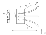
- FIG. 20 is a side view showing an outline of a total heat exchanger 100 further including a first fan 60.
- a first fan 60 for blowing air to the heat exchange element 10 and the heat storage section 30 may be further provided around the heat exchange element 10 on one side A or the other side B of the heat exchange element 10.
- the first fan 60 is provided, for example, on the first opening 12a side of the heat exchange element 10, and the blown air enters from the first opening 12a and passes through the air passage 11 to pass through the second opening 12b.
- the blown air also passes through the heat storage section 30 and passes from side A to side B. In this way, it is possible to have a humidity control function and to enable efficient heat exchange. It is also possible to prevent variations in the amount of air and to enable efficient heat exchange.
- the axis P1 of the first fan 60 is parallel to the air passage 11 that blows air through the heat exchange element 10.
- the air blowing direction of the first fan 60 is parallel to the air passage 11.
- the center of the heat exchange element 10 is positioned on the axis P1 of the first fan 60.
- the size of the arrow in FIG. 20 indicates the size of the air volume.
- a fan is provided near the heat exchange element 10
- the air volume near the center of the heat exchange element 10 is smaller than that on the outside.
- the air volume near the center of the heat exchange element 10 is larger than that on the outside.
- a heat storage unit 30 having a filter 33 as shown in FIG. 5 is provided to suppress the variation in the air volume blown through the heat exchange element 10.
- a filter 33 is provided at the opening 31 on the B side of the heat storage unit 30 to limit the air volume near the center of the heat exchange element 10 and suppress the overall variation in the air volume.
- FIG. 21 is a side view showing an outline of a total heat exchanger 100 further including a first fan 60 and a second fan 70.
- a first fan 60 for blowing air to the heat exchange element 10 and the heat storage section 30 may be provided on one side A or the other side B of the heat exchange element 10
- the first fan 60 and the second fan 70 may be an axial fan or a blower fan equipped with a propeller.
- the axis P1 of the first fan 60 and the axis P2 of the second fan 70 are parallel to the air passage 11 that blows air through the heat exchange element 10.
- the air blowing directions of the first fan 60 and the second fan 70 are parallel to the air passage 16.
- the center of the heat exchange element 10 is positioned on the axis P1 of the first fan 60 and the axis P2 of the second fan 70.
- first fan 60 and the second fan 70 may have different rotation directions and fan angles, but the same air blowing direction.
- first fan 60 rotates clockwise
- second fan 70 rotates counterclockwise
- the fan angles of the first fan 60 and the second fan 70 are opposite, resulting in the same air blowing direction.
- the variation in air volume between the center and the outside of the heat exchange element 10, which will be described later can be further improved.
- condensation due to excessive moisture absorption by the humidity control material 20 can be further prevented.
- Figure 22 is a side view showing an outline of a total heat exchanger 100 in which a sensible heat section 50 is provided in the heat exchange element 10.
- a sensible heat section 50 may be further provided on one side A or the other side B of the heat exchange element 10.
- the sensible heat section 50 releases heat from the heat exchange element 10 and the heat recovery section 40. In this way, heat exchange can be promoted and the heat capacity of the total heat exchanger 100 can be increased.
- the sensible heat section 50 is preferably made of a metal with high thermal conductivity such as aluminum, iron, or copper.
- the sensible heat section 50 may be provided with a tapered section 51 on one side A or the other side B of the heat exchange element 10.
- the first fan 60 is provided on one side A of the heat exchange element 10
- FIG. 24 is a perspective view showing a modified example of the heat exchange element 10.
- FIG. 25 is a front view showing a modified example of the heat exchange element 10. As shown in FIGS. 24 and 25, the heat exchange element 10 may have a honeycomb shape.
- FIG. 26 is a perspective view showing another modified example of the heat exchange element 10.
- FIG. 27 is a front view showing another modified example of the heat exchange element 10.
- two heat exchange elements 10', 10'' may be used and overlapped in the X direction.
- the overlapping position in the X direction may be offset in the Z direction or Y direction.
- the opening 12'a of the heat exchange element 10' placed in the front and the opening 12''a of the heat exchange element 10'' placed in the back are offset.
- the total heat exchanger 100 disclosed herein has a humidity control function, reduces thermal resistance, and enables efficient heat exchange.
- the ventilation device 200 may include a plurality of total heat exchangers 100. If the total heat exchangers 100 are at least a first total heat exchanger 101 and a second total heat exchanger 102, as shown in FIG. 28, while the first total heat exchanger 101 supplies air to the space 80, the second total heat exchanger 102 exhausts air from the space 80. After a predetermined time has elapsed, for example, several tens of seconds, as shown in FIG. 29, the first total heat exchanger 101 exhausts air from the space 80, and the second total heat exchanger 102 supplies air to the space 80. The supply and exhaust of the first total heat exchanger 101 and the second total heat exchanger 102 are switched at a predetermined time interval. In this way, the ventilation device 200 according to the present disclosure may be of a time-division type in which the supply and exhaust are switched after a predetermined time has elapsed. In this way, the space 80 can be ventilated while exchanging heat more efficiently.
- the space 80 may be, for example, a room or the interior of a car or train. Therefore, the ventilation device 200 according to the present disclosure may be for residential or vehicle use. Furthermore, the ventilation device 200 may be configured by installing a total heat exchanger 100 at the boundary between the rooms separated by a space, without being limited to residential or vehicle use.
- the ventilation device 200 has a humidity control function, reduces thermal resistance, and enables efficient heat exchange.
Landscapes
- Engineering & Computer Science (AREA)
- General Engineering & Computer Science (AREA)
- Chemical & Material Sciences (AREA)
- Mechanical Engineering (AREA)
- Thermal Sciences (AREA)
- Physics & Mathematics (AREA)
- Combustion & Propulsion (AREA)
- Life Sciences & Earth Sciences (AREA)
- Sustainable Development (AREA)
- Dispersion Chemistry (AREA)
- Analytical Chemistry (AREA)
- General Chemical & Material Sciences (AREA)
- Oil, Petroleum & Natural Gas (AREA)
- Chemical Kinetics & Catalysis (AREA)
- Central Air Conditioning (AREA)
- Heat-Exchange Devices With Radiators And Conduit Assemblies (AREA)
Priority Applications (3)
| Application Number | Priority Date | Filing Date | Title |
|---|---|---|---|
| EP23894339.3A EP4624856A4 (en) | 2022-11-22 | 2023-10-25 | TOTAL HEAT EXCHANGER AND FAN |
| JP2024560024A JPWO2024111327A1 (https=) | 2022-11-22 | 2023-10-25 | |
| CN202380080997.3A CN120265934A (zh) | 2022-11-22 | 2023-10-25 | 全热交换器及换气装置 |
Applications Claiming Priority (2)
| Application Number | Priority Date | Filing Date | Title |
|---|---|---|---|
| JP2022186259 | 2022-11-22 | ||
| JP2022-186259 | 2022-11-22 |
Publications (1)
| Publication Number | Publication Date |
|---|---|
| WO2024111327A1 true WO2024111327A1 (ja) | 2024-05-30 |
Family
ID=91195462
Family Applications (1)
| Application Number | Title | Priority Date | Filing Date |
|---|---|---|---|
| PCT/JP2023/038411 Ceased WO2024111327A1 (ja) | 2022-11-22 | 2023-10-25 | 全熱交換器及び換気装置 |
Country Status (4)
| Country | Link |
|---|---|
| EP (1) | EP4624856A4 (https=) |
| JP (1) | JPWO2024111327A1 (https=) |
| CN (1) | CN120265934A (https=) |
| WO (1) | WO2024111327A1 (https=) |
Citations (5)
| Publication number | Priority date | Publication date | Assignee | Title |
|---|---|---|---|---|
| JPS5213153A (en) * | 1975-07-17 | 1977-02-01 | Aero Flow Dynamics Inc | Apparatus for exchanging heat energy and method of manufacturing the apparatus |
| JP2007240125A (ja) * | 2006-03-13 | 2007-09-20 | Matsushita Electric Ind Co Ltd | 換気装置 |
| CN104374034A (zh) * | 2014-11-25 | 2015-02-25 | 宁波东大空调设备有限公司 | 一种无管道蓄热式净化新风机 |
| JP2019148344A (ja) * | 2018-02-26 | 2019-09-05 | クリスティアン ドイティンガー | 換気システム |
| JP2022186259A (ja) | 2021-06-04 | 2022-12-15 | 株式会社荏原製作所 | 水中モータポンプ |
Family Cites Families (4)
| Publication number | Priority date | Publication date | Assignee | Title |
|---|---|---|---|---|
| JP2005052694A (ja) | 2003-08-05 | 2005-03-03 | Chugoku Electric Power Co Inc:The | 除湿ローター、それを用いたデシカント除湿装置並びにデシカント空調装置、およびデシカント除湿方法 |
| JP2009097837A (ja) * | 2007-10-19 | 2009-05-07 | Shin Nippon Air Technol Co Ltd | 調湿調温デシカントロータ及びこれを用いたデシカント換気システム |
| KR101453739B1 (ko) * | 2014-04-01 | 2014-10-22 | 주식회사 원방테크 | 마이크로웨이브 히터가 적용된 로터형 건식 제습기 |
| EP3168544B1 (de) * | 2015-11-12 | 2018-05-02 | InVENTer GmbH | Belüftungsvorrichtung |
-
2023
- 2023-10-25 CN CN202380080997.3A patent/CN120265934A/zh active Pending
- 2023-10-25 EP EP23894339.3A patent/EP4624856A4/en active Pending
- 2023-10-25 JP JP2024560024A patent/JPWO2024111327A1/ja active Pending
- 2023-10-25 WO PCT/JP2023/038411 patent/WO2024111327A1/ja not_active Ceased
Patent Citations (5)
| Publication number | Priority date | Publication date | Assignee | Title |
|---|---|---|---|---|
| JPS5213153A (en) * | 1975-07-17 | 1977-02-01 | Aero Flow Dynamics Inc | Apparatus for exchanging heat energy and method of manufacturing the apparatus |
| JP2007240125A (ja) * | 2006-03-13 | 2007-09-20 | Matsushita Electric Ind Co Ltd | 換気装置 |
| CN104374034A (zh) * | 2014-11-25 | 2015-02-25 | 宁波东大空调设备有限公司 | 一种无管道蓄热式净化新风机 |
| JP2019148344A (ja) * | 2018-02-26 | 2019-09-05 | クリスティアン ドイティンガー | 換気システム |
| JP2022186259A (ja) | 2021-06-04 | 2022-12-15 | 株式会社荏原製作所 | 水中モータポンプ |
Non-Patent Citations (1)
| Title |
|---|
| See also references of EP4624856A1 |
Also Published As
| Publication number | Publication date |
|---|---|
| EP4624856A1 (en) | 2025-10-01 |
| EP4624856A4 (en) | 2026-03-11 |
| CN120265934A (zh) | 2025-07-04 |
| JPWO2024111327A1 (https=) | 2024-05-30 |
Similar Documents
| Publication | Publication Date | Title |
|---|---|---|
| US10655870B2 (en) | Methods for enhancing the dehumidification of heat pumps | |
| WO2023248560A1 (ja) | 全熱交換素子及び換気装置 | |
| JP2011143358A (ja) | 吸湿フィルタおよび加湿装置 | |
| JP3918852B2 (ja) | 吸着熱交換器の製造方法及び製造装置 | |
| WO2024111327A1 (ja) | 全熱交換器及び換気装置 | |
| JP4919498B2 (ja) | 冷房空調システム | |
| JPS62297647A (ja) | 建築物の除湿システム | |
| WO2024004319A1 (ja) | 全熱交換器及び換気装置 | |
| JPH04148194A (ja) | 吸着剤付き熱交換器 | |
| JP2013204822A (ja) | デシカント空調システム | |
| CN120659957A (zh) | 热交换装置及全热交换换气系统 | |
| JP5628607B2 (ja) | 空調システム | |
| CN214120261U (zh) | 一种无水加湿装置及加湿空调 | |
| WO2024252775A1 (ja) | 熱交換型換気装置及び全熱交換換気システム | |
| CN112268328A (zh) | 一种无水加湿方法、控制器、无水加湿装置及储存介质 | |
| WO2025197658A1 (ja) | 調湿エレメント及び全熱交換装置 | |
| WO2025089059A1 (ja) | 全熱交換ユニット | |
| JP7674264B2 (ja) | 除湿装置 | |
| JPWO2024166509A5 (https=) | ||
| WO2025100185A1 (ja) | 調湿装置 | |
| WO2025197442A1 (ja) | 除湿装置 | |
| CN207962977U (zh) | 一种带有调湿溶液的散热系统 | |
| AU2019393829B2 (en) | An apparatus for removing water from a fluid | |
| JP2001330273A (ja) | 固体吸湿剤を用いた冷房システム | |
| CN108253558A (zh) | 一种带有调湿溶液的散热系统 |
Legal Events
| Date | Code | Title | Description |
|---|---|---|---|
| 121 | Ep: the epo has been informed by wipo that ep was designated in this application |
Ref document number: 23894339 Country of ref document: EP Kind code of ref document: A1 |
|
| WWE | Wipo information: entry into national phase |
Ref document number: 2024560024 Country of ref document: JP |
|
| WWE | Wipo information: entry into national phase |
Ref document number: 2501003366 Country of ref document: TH Ref document number: 202380080997.3 Country of ref document: CN |
|
| WWE | Wipo information: entry into national phase |
Ref document number: 2023894339 Country of ref document: EP |
|
| NENP | Non-entry into the national phase |
Ref country code: DE |
|
| ENP | Entry into the national phase |
Ref document number: 2023894339 Country of ref document: EP Effective date: 20250623 |
|
| WWP | Wipo information: published in national office |
Ref document number: 202380080997.3 Country of ref document: CN |
|
| WWP | Wipo information: published in national office |
Ref document number: 2023894339 Country of ref document: EP |