WO2024111049A1 - 空気清浄機および空気調和装置 - Google Patents
空気清浄機および空気調和装置 Download PDFInfo
- Publication number
- WO2024111049A1 WO2024111049A1 PCT/JP2022/043176 JP2022043176W WO2024111049A1 WO 2024111049 A1 WO2024111049 A1 WO 2024111049A1 JP 2022043176 W JP2022043176 W JP 2022043176W WO 2024111049 A1 WO2024111049 A1 WO 2024111049A1
- Authority
- WO
- WIPO (PCT)
- Prior art keywords
- discharge
- electrode
- air purifier
- electrodes
- air
- Prior art date
- Legal status (The legal status is an assumption and is not a legal conclusion. Google has not performed a legal analysis and makes no representation as to the accuracy of the status listed.)
- Ceased
Links
Images







Classifications
-
- A—HUMAN NECESSITIES
- A61—MEDICAL OR VETERINARY SCIENCE; HYGIENE
- A61L—METHODS OR APPARATUS FOR STERILISING MATERIALS OR OBJECTS IN GENERAL; DISINFECTION, STERILISATION OR DEODORISATION OF AIR; CHEMICAL ASPECTS OF BANDAGES, DRESSINGS, ABSORBENT PADS OR SURGICAL ARTICLES; MATERIALS FOR BANDAGES, DRESSINGS, ABSORBENT PADS OR SURGICAL ARTICLES
- A61L9/00—Disinfection, sterilisation or deodorisation of air
- A61L9/16—Disinfection, sterilisation or deodorisation of air using physical phenomena
- A61L9/22—Ionisation
-
- F—MECHANICAL ENGINEERING; LIGHTING; HEATING; WEAPONS; BLASTING
- F24—HEATING; RANGES; VENTILATING
- F24F—AIR-CONDITIONING; AIR-HUMIDIFICATION; VENTILATION; USE OF AIR CURRENTS FOR SCREENING
- F24F8/00—Treatment, e.g. purification, of air supplied to human living or working spaces otherwise than by heating, cooling, humidifying or drying
- F24F8/30—Treatment, e.g. purification, of air supplied to human living or working spaces otherwise than by heating, cooling, humidifying or drying by ionisation
-
- H—ELECTRICITY
- H01—ELECTRIC ELEMENTS
- H01T—SPARK GAPS; OVERVOLTAGE ARRESTERS USING SPARK GAPS; SPARKING PLUGS; CORONA DEVICES; GENERATING IONS TO BE INTRODUCED INTO NON-ENCLOSED GASES
- H01T19/00—Devices providing for corona discharge
- H01T19/04—Devices providing for corona discharge having pointed electrodes
-
- H—ELECTRICITY
- H01—ELECTRIC ELEMENTS
- H01T—SPARK GAPS; OVERVOLTAGE ARRESTERS USING SPARK GAPS; SPARKING PLUGS; CORONA DEVICES; GENERATING IONS TO BE INTRODUCED INTO NON-ENCLOSED GASES
- H01T23/00—Apparatus for generating ions to be introduced into non-enclosed gases, e.g. into the atmosphere
Definitions
- This disclosure relates to an air purifier and air conditioner equipped with a generation unit that generates chemical species such as discharge products by discharging at high voltage.
- an air purifier that applies a high voltage between electrodes to generate discharge products, which are supplied into the air and then transported to a treatment target such as bacteria or viruses, thereby sterilizing bacteria or inactivating viruses.
- This type of air purifier is equipped with a generator that generates discharge products such as ions.
- An example of a conventional generator is the ion generating device disclosed in Patent Document 1.
- the ion generating device disclosed in Patent Document 1 is equipped with a plurality of rod-shaped discharge electrodes arranged in parallel, a plurality of induction electrodes arranged opposite the plurality of discharge electrodes in the axial direction of the discharge electrodes, and a high voltage application unit that applies a high voltage between the discharge electrodes and the induction electrodes.
- the ion generating device disclosed in Patent Document 1 generates discharge products between a plurality of discharge electrodes and a plurality of opposing electrodes.
- the ion generating device of Patent Document 1 multiple discharge electrodes are charged to the same pole, and many of the discharge products generated from the multiple discharge electrodes are charged to the same pole. Homogeneously charged discharge products repel each other, and there is a risk that the repulsion will cause the discharge products to diffuse and the supply direction will not be determined. For this reason, when the ion device of Patent Document 1 is applied to an air purifier, the discharge products are not transported to the treatment target in a concentration required for killing bacteria or inactivating viruses. Therefore, the air purifier has a problem in that it cannot fully kill bacteria and inactivate viruses (hereinafter referred to as the killing and inactivating virus effect).
- the present disclosure has been made in consideration of these points, and aims to provide an air purifier and air conditioner that can suppress the diffusion of discharge products and improve the sterilization and virus inactivation effects.
- the air conditioning device has the above air purifier, a heat exchanger that exchanges heat between the refrigerant flowing inside and the surrounding air, and a blower that forms an air flow and is positioned upstream of a plurality of first discharge electrodes to supply discharge products into a space, and the air supplied by the blower passes through the heat exchanger, and the air that has passed through the heat exchanger and been conditioned supplies the discharge products into the air.
- the air purifier and air conditioner disclosed herein have a plurality of discharge electrodes that are formed extending in a first direction and are arranged at intervals in a second direction perpendicular to the first direction.
- an induction electrode that forms an electric field between the plurality of first discharge electrodes is arranged at the center of the plurality of first discharge electrodes as viewed in the first direction. Therefore, the air purifier can collect discharge products generated from the plurality of discharge electrodes toward the induction electrode in a direction in which the discharge products approach each other as viewed in the first direction, thereby suppressing the diffusion of the discharge products and increasing their concentration. Therefore, the air purifier can transport the discharge products in a highly concentrated state toward the treatment target, improving the sterilization and virus inactivation effect.
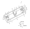
- FIG. 1 is a schematic perspective view of an air purifier according to a first embodiment.
- 2 is a schematic perspective view of the generation unit of the air purifier according to the first embodiment, viewed from below.
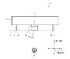
- FIG. 2 is a schematic side view of a generation unit of the air purifier according to the first embodiment.
- FIG. 11 is a diagram showing an electric field formed around a first discharge electrode in a comparative example.
- FIG. 4 is a schematic diagram showing the behavior of discharge products in a comparative example.
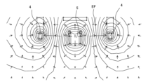
- 5A and 5B are diagrams illustrating an electric field formed between a first discharge electrode and an induction electrode in the air purifier according to the first embodiment.
- 5A to 5C are schematic diagrams showing the behavior of discharge products in the air purifier according to the first embodiment.
- FIG. 11 is a perspective view showing a modified example of the air purifier according to the first embodiment.
- FIG. 11 is a schematic side view of an air purifier according to a second embodiment.
- 11A and 11B are schematic diagrams showing the behavior of discharge products in an air purifier according to a second embodiment.
- FIG. 11 is a schematic diagram showing the behavior of discharge products in the air purifier according to embodiment 1 as a comparative example.
- FIG. 11 is a schematic perspective view of an air purifier according to a third embodiment.
- 11 is a schematic perspective view of the generation unit of the air purifier according to embodiment 3, viewed from below.
- FIG. 11 is a schematic cross-sectional view of a generation section of an air purifier according to embodiment 3.
- FIG. 11 is a schematic cross-sectional view of a generation section of an air purifier according to embodiment 3.
- FIG. 1 is a schematic perspective view of an air purifier 1 according to embodiment 1.
- Fig. 2 is a schematic perspective view of the generation unit 2 of the air purifier 1 according to embodiment 1, as viewed from below.
- Fig. 3 is a schematic side view of the generation unit 2 of the air purifier 1 according to embodiment 1.
- arrows X, Y, and Z respectively indicate three directions perpendicular to each other. The X direction indicates the left-right direction, the Z direction indicates the up-down direction, and the Y direction indicates the front-rear direction.
- Air purifier 1 is a device that purifies the air in the space S in which it is installed. More specifically, air purifier 1 is a device that sterilizes bacteria or inactivates viruses present in the space. Air purifier 1 may be configured to function as a so-called air conditioning device, such as a device with a temperature control function and a humidity control function, or a device with a ventilation function.
- air conditioning device such as a device with a temperature control function and a humidity control function, or a device with a ventilation function.
- the air purifier 1 has a high-voltage conversion unit (not shown) that converts an input voltage into a high voltage, a generation unit 2 that generates a discharge product DP1 (see FIG. 7 described below), and a blower unit 3 that supplies the discharge product DP1 generated from the generation unit 2 to a space S.
- the discharge product DP1 is supplied to the space S in the direction of the white arrow in FIG. 1.
- the discharge product DP1 supplied to the space S is transported to a treatment object W present in the space S, and treats the treatment object W.
- the treatment object W is bacteria, viruses, or both. "Treating the treatment object W" means sterilizing bacteria, inactivating viruses, or both.
- the generating section 2 has a plurality of first discharge electrodes 4, an induction electrode 5, and a frame-shaped holding member 6 that holds the plurality of first discharge electrodes 4 and the induction electrode 5.
- the first discharge electrodes 4 are formed to extend in a first direction indicated as the Z direction in the figure.
- the plurality of first discharge electrodes 4 are arranged at intervals in a second direction perpendicular to the first direction.
- the second direction is a planar direction perpendicular to the first direction, and includes the X direction and the Y direction.
- the number of first discharge electrodes 4 is two, but is not limited to two, and may be two or more.
- the first discharge electrode 4 is composed of a cone-shaped needle electrode whose diameter decreases from the base end to the tip end. One of the ends of the first discharge electrode 4 in the first direction is the tip end, and the other is the base end. The base end of the first discharge electrode 4 is held by the first holding part 11 described later of the holding member 6.
- the first discharge electrode 4 has a discharge point 4a at the tip end, which is composed of a needle-shaped tip and where discharge occurs.
- the first discharge electrode 4 is held by the first holding part 11 so that the discharge point 4a protrudes downward from the lower end surface 11a of the first holding part 11 and the lower end surface 15a of the frame part 15 described later.
- the material of the first discharge electrode 4 is metal.
- the material of the first discharge electrode 4 is not limited to metal, and may be formed from other conductive materials, such as conductive carbon fiber.
- the induction electrode 5 is formed to extend in the first direction, similar to the first discharge electrode 4.
- the induction electrode 5 is formed in a cylindrical shape.
- the induction electrode 5 is disposed at the center of the multiple first discharge electrodes 4 when viewed in the first direction.
- the induction electrode 5 is disposed side-by-side with the multiple first discharge electrodes 4.
- the material of the induction electrode 5 is metal. Note that the material of the induction electrode 5 is not limited to metal, and may be formed from other conductive materials, such as conductive carbon fiber.
- the induction electrode 5 has a base end 5a that is held by a second holding portion 13 (described later) of the holding member 6, and a tip end 5b on the opposite side to the base end 5a.
- the induction electrode 5 is arranged so that the tip surface 5b1 of the tip end 5b overlaps with an imaginary line L that connects the discharge points 4a of the multiple first discharge electrodes 4.
- the induction electrode 5 is arranged in the second direction such that the central axis O of the induction electrode 5 coincides with the central axis of the blower section 3. Note that there is no particular limitation on whether the central axis O of the induction electrode 5 coincides with the central axis of the housing (not shown) of the air purifier 1, and they may or may not coincide.
- the first holding parts 11 are provided in the same number as the number of first discharge electrodes 4, and here there are two.
- the two first holding parts 11 are fixed inside the frame part 15 with a space between them.
- the first holding parts 11 are formed in a cylindrical shape that surrounds the periphery of the first discharge electrode 4.
- the first holding parts 11 are fixed to the frame part 15 by a pair of fixing legs 12 that extend in opposite directions from the outer circumferential surface of the first holding parts 11.
- the end of the first discharge electrode 4 opposite the discharge point 4a is inserted into the first holding parts 11 and fixed to the first holding parts 11.
- the first discharge electrode 4 is fixed to the first holding parts 11 by inserting a fixing member (not shown) between the outer circumferential surface of the first discharge electrode 4 and the inner circumferential surface of the first holding parts 11.
- the second holding portion 13 is disposed at the center of the two second holding portions 13 when viewed in the first direction.
- the second holding portion 13 is formed in a cylindrical shape surrounding the periphery of the induction electrode 5.
- the second holding portion 13 is fixed to the frame portion 15 by a pair of fixing legs 14 extending in opposite directions from the outer circumferential surface of the second holding portion 13.
- the induction electrode 5 is held by the second holding portion 13 with the base end portion 5a of the induction electrode 5 inserted into the second holding portion 13.
- the induction electrode 5 is fixed to the second holding portion 13 by inserting a fixing member (not shown) between the outer circumferential surface of the induction electrode 5 and the inner circumferential surface of the second holding portion 13.
- the fixing member is, for example, an electrically insulating resin part, a potting material, or an adhesive.
- the air near the first discharge electrode 4 is ionized to generate discharge products DP1 such as negative ions or positive ions.
- the polarity of electricity applied to the multiple first discharge electrodes 4 is the same. In other words, the multiple first discharge electrodes 4 are electrodes of the same polarity. Therefore, all of the multiple first discharge electrodes 4 are of the same polarity.
- the polarity of electricity applied to the first discharge electrode 4 is negative here, but is not limited to negative and may be positive.
- the polarity of the ions generated from the first discharge electrode 4 depends on the polarity of the high voltage applied from the high voltage conversion unit.
- the ions generated from the first discharge electrode 4 are negative ions when the polarity of the high voltage applied from the high voltage conversion unit is negative, and positive ions when the polarity is positive.
- When a high voltage is applied to the negative pole of the first discharge electrode 4 electrons are emitted from the first discharge electrode 4, and these electrons combine with oxygen or water present in the air near the first discharge electrode 4 to generate the discharge product DP1.
- the electric field formed between the first discharge electrode 4 and the induction electrode 5 can be concentrated at the discharge point 4a at the tip of the first discharge electrode 4.
- the electric field EF see FIG. 6 described later
- the electric field can be concentrated at the discharge point 4a at the tip of the first discharge electrode 4, making it easy to emit electrons.
- the first discharge electrode 4 is preferably in a shape with a tapered tip such as a needle-shaped electrode, but is not limited to this shape and may be columnar.
- the first discharge electrode 4 may also be an electrode made of equal fine wires or a brush-shaped electrode made of a bundle of fine wires.
- the induction electrode 5 forms an electric field EF between itself and the first discharge electrodes 4, and attracts the discharge product DP1 generated from the first discharge electrodes 4.
- the induction electrode 5 is grounded or has a different polarity applied to it than the first discharge electrodes 4.
- an electric field EF is formed between the induction electrode 5 and the first discharge electrodes 4.
- the blower 3 is composed of a fan, and forms an air flow to generate wind.
- the blower 3 supplies the discharge product DP1 generated from the generation unit 2 into the space S by wind.
- the discharge product DP1 supplied into the space S reaches the surfaces of furniture such as desks in the room, and acts on and treats bacteria and viruses attached to the surfaces.
- the blower 3 is disposed near the generation unit 2.
- the blower 3 is disposed upstream of the generation unit 2. If the blower 3 is disposed downstream of the generation unit 2, the discharge product DP1 generated from the generation unit 2 may be agitated and diffused by passing through the blower 3. For this reason, the blower 3 is disposed upstream of the generation unit 2.
- the fan is, for example, an axial propeller fan.
- an axial propeller fan By using an axial propeller fan as the blower fan, the blower fan can generate a large volume of airflow.
- the motor connected to the blower fan is a general AC capacitor motor, but is not limited to an AC capacitor motor.
- FIG. 4 is a diagram showing the electric field EF formed around the first discharge electrode 4 in the comparative example.
- FIG. 5 is a schematic diagram showing the behavior of the discharge product DP1 in the comparative example.
- FIG. 4 shows a case where there is no induction electrode 5 between the multiple first discharge electrodes 4 and the high voltage applied to the first discharge electrode 4 is negative. Since the high voltage applied to the first discharge electrode 4 is negative, the direction of the electric field EF is from the outside toward the first discharge electrode 4. In FIG. 4, the electric field EF is indicated by an arrow. Since the high voltage applied to the first discharge electrode 4 is negative, negative ions are generated as the discharge product DP1 from the first discharge electrode 4 as shown in FIG. 5.
- the negative ions are negatively charged, a force in the opposite direction to the electric field EF is applied. Therefore, in the comparative example, as shown in FIG. 5, the negative ions generated from the multiple first discharge electrodes 4 of the same polarity repel each other and diffuse. Therefore, in the comparative example, the concentration of the discharge product DP1 that reaches the treatment target W is low.
- FIG. 6 is a diagram showing the electric field EF formed between the first discharge electrode 4 and the induction electrode 5 in the air purifier 1 according to the first embodiment.
- FIG. 7 is a schematic diagram showing the behavior of the discharge product DP1 in the air purifier 1 according to the first embodiment.
- FIGS. 6 and 7 show the case where the high voltage applied to the first discharge electrode 4 is negative.
- the direction of the electric field EF is from the induction electrode 5 to the first discharge electrode 4. Also, because the high voltage applied to the first discharge electrode 4 is negative, negative ions are generated from the first discharge electrode 4. Since the negative ions are negatively charged, a force in the opposite direction to the electric field EF acts on them. Therefore, as shown in Figure 7, the negative ions are subjected to a force from the first discharge electrode 4 toward the induction electrode 5, and are attracted to the induction electrode 5 as indicated by the white arrow.
- the induction electrode 5 is disposed at the center of the multiple first discharge electrodes 4 when viewed in the first direction. Therefore, the negative ions generated from each of the multiple first discharge electrodes 4 are collected at the center of the multiple first discharge electrodes 4 when viewed in the first direction. In other words, the negative ions generated from each of the multiple first discharge electrodes 4 are collected toward the induction electrode 5 in a direction in which they approach each other when viewed in the first direction. Furthermore, the induction electrode 5 is disposed side by side with the multiple first discharge electrodes 4.
- the induction electrode 5 is not disposed side by side with the multiple first discharge electrodes 4, that is, if the induction electrode 5 is disposed opposite the multiple first discharge electrodes 4 in the first direction, there is a possibility that repulsion of the discharge product DP1 as shown in FIG. 5 will occur. For this reason, the induction electrode 5 is disposed side by side with the multiple first discharge electrodes 4.
- the air purifier 1 can collect the negative ions generated from each of the multiple first discharge electrodes 4 in a direction approaching each other, suppressing the diffusion of the negative ions and increasing their concentration. Therefore, the air purifier 1 can transport negative ions at a high concentration to the treatment target W even if the treatment target W is located away from the air purifier 1. In this way, the air purifier 1 can transport negative ions at a high concentration to the treatment target W, thereby achieving a high sterilization and virus inactivation effect.
- the direction of the electric field EF is from the first discharge electrode 4 toward the induction electrode 5.
- the high voltage applied to the first discharge electrode 4 is positive, positive ions are generated from the first discharge electrode 4. Since positive ions are positively charged, a force in the same direction as the electric field EF acts on the positive ions. In other words, a force acts on the positive ions in the direction from the first discharge electrode 4 toward the induction electrode 5, just like negative ions, and the positive ions are attracted to the induction electrode 5. Therefore, even when the high voltage applied to the first discharge electrode 4 is positive, the air purifier 1 can obtain the same effect as when the high voltage applied to the first discharge electrode 4 is negative, as described above.
- FIG. 1 there are two first discharge electrodes 4, but there may be two or more first discharge electrodes 4.
- FIG. 8 shows an example of an arrangement in which there are four first discharge electrodes 4.
- FIG. 8 is a perspective view showing a modified example of the air purifier 1 according to the first embodiment.
- the modified example of FIG. 4 there are four first discharge electrodes 4, and the four first discharge electrodes 4 are arranged at intervals in a circular shape in the second direction.
- the induction electrode 5 is arranged in the center of the four first discharge electrodes 4 when viewed in the first direction.
- the air purifier 1 includes a plurality of first discharge electrodes 4, and supplies discharge products DP1 generated from the plurality of first discharge electrodes 4 toward a treatment target W in a space S to purify the air in the space.
- the plurality of first discharge electrodes 4 are formed extending in a first direction, and are electrodes of the same polarity arranged at intervals in a second direction perpendicular to the first direction.
- the air purifier 1A includes an induction electrode 5 that forms an electric field between itself and the plurality of first discharge electrodes 4, and that is arranged in the center of the plurality of first discharge electrodes 4 as viewed in the first direction.
- the air purifier 1 can collect the discharge products DP1 generated from the multiple first discharge electrodes 4 toward the induction electrode in a direction approaching each other when viewed in the first direction, suppressing the diffusion of the discharge products and increasing their concentration. Therefore, the air purifier can transport the discharge products DP1 in a highly concentrated state toward the treatment target, improving the sterilization and virus inactivation effect.
- the air purifier 1 is equipped with a holding member 6 that is electrically insulating and holds a plurality of first discharge electrodes 4 and an induction electrode 5.
- Each of the plurality of first discharge electrodes 4 has a discharge point 4a, which is formed of a needle-shaped tip and where discharge occurs, at one of both ends in the first direction, and the end opposite the discharge point 4a is held by the holding member 6.
- the tip of the first discharge electrode 4 is not needle-shaped, it becomes necessary to increase the voltage or place the induction electrode 5 near the first discharge electrode 4 in order to cause a discharge.
- Increasing the voltage has the disadvantage of unavoidably increasing the size and cost of the power supply.
- Placing the induction electrode 5 near the first discharge electrode 4 causes problems such as the generation of ozone in addition to ions.
- the end of the first discharge electrode 4 opposite the discharge point 4a is not held by the holding member 6, there is a possibility that the first discharge electrode 4 may come into contact with the metal housing that constitutes the outer shell of the air purifier 1 when voltage is applied, resulting in abnormal discharge or leakage.
- the air purifier 1 can avoid the above problem because the tip of the first discharge electrode 4 is needle-shaped and the end of the first discharge electrode 4 opposite the discharge point 4a is held by a holding member 6.
- Embodiment 2 The air purifier 1A according to the second embodiment differs from the air purifier 1 according to the first embodiment in the position in the first direction of the tip surface 5b1 of the induction electrode 5.
- the following description will focus on the differences between the second embodiment and the first embodiment, and the configuration not described in the second embodiment is the same as that of the first embodiment.
- FIG. 9 is a schematic side view of an air purifier 1A according to embodiment 2.
- Air purifier 1A differs from air purifier 1 of embodiment 1 in that tip surface 5b1 of induction electrode 5 is located closer to the treatment target W side than imaginary line L in the first direction. The rest of the configuration is the same as air purifier 1 of embodiment 1.
- the specific structure for positioning tip surface 5b1 of induction electrode 5 at the above position is not particularly limited, and may be, for example, as follows.
- air purifier 1A may be structured such that the length of second holding portion 13 in the first direction is extended toward the treatment target W side compared to air purifier 1, and base end portion 5a of induction electrode 5 is inserted and fixed inside the extended portion.
- FIG. 10 is a schematic diagram showing the behavior of discharge product DP1 in air purifier 1A according to embodiment 2.
- FIG. 11 is a schematic diagram showing the behavior of discharge product DP1 in air purifier 1 according to embodiment 1 as a comparative example.
- the distance between discharge product group DPg in the part circled with a solid line and induction electrode 5 is closer than in embodiment 1 shown in FIG. 11.
- distance l1 in FIG. 10 is shorter than distance l2 in FIG. 11.
- discharge product group DPg is more susceptible to the attractive effect of induction electrode 5, and diffusion of discharge product DP1 can be suppressed to further increase the concentration.
- Discharge product DPs1 surrounded by a dotted circle in FIG. 10 and discharge product DPs2 surrounded by a dotted circle in FIG. 11 are discharge products DP1 that are the same distance from the holding member 6 in the first direction. Because the tip surface 5b1 of the induction electrode 5 is located closer to the treatment target W than the imaginary line L, the discharge product DPs1 and the discharge product DPs2 exhibit the following different behaviors.
- the discharge product DPs2 in FIG. 11 is attracted laterally to the induction electrode 5 as shown by the arrow r2.
- the discharge product DPs1 in FIG. 10 is attracted diagonally downward as shown by the arrow r1, in other words, in the direction approaching the treatment target W. For this reason, the air purifier 1A can accelerate and attract the discharge product DPs1 toward the treatment target W, and can increase the concentration of the discharge product DP1 that reaches the treatment target W compared to the air purifier 1.
- the air purifier 1A can obtain the same effects as the air purifier 1, and can also obtain the following effects.
- the tip surface 5b1 of the induction electrode 5 is located closer to the treatment target W in the first direction than the virtual line L, so that the discharge product DP1 is more susceptible to the attraction effect of the induction electrode 5 than in the air purifier 1.
- the air purifier 1A can suppress the diffusion of the discharge product DP1 and increase the concentration more than the air purifier 1.
- the air purifier 1A can transport the discharge product DP1 to the treatment target at a higher concentration than the air purifier 1, and can enhance the sterilization and virus inactivation effect.
- Embodiment 3 differs from air purifier 1 according to embodiment 1 and air purifier 1A according to embodiment 2 in that it further includes a second discharge electrode and in the shape of the induction electrode 5.
- the following description will focus on the differences between embodiment 3 and embodiment 1, and configurations not described in embodiment 3 are similar to embodiment 1.
- FIG. 12 is a schematic perspective view of air purifier 1B according to embodiment 3.
- FIG. 13 is a schematic perspective view of generation unit 2 of air purifier 1B according to embodiment 3, seen from below.
- FIG. 14 is a schematic cross-sectional view of generation unit 2 of air purifier 1B according to embodiment 3.
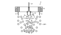
- FIG. 15 is a schematic diagram showing the behavior of discharge product DP1 and discharge product DP2 in air purifier 1B according to embodiment 3.
- Air purifier 1B includes a second discharge electrode 21 in addition to the components of air purifier 1.
- the second discharge electrode 21 is fixed to the second holding portion 13 by being surrounded by an electrically insulating resin part (not shown), or is fixed to the second holding portion 13 by screws or adhesive.
- the shape of induction electrode 5B is cylindrical, unlike induction electrode 5 of embodiment 1.
- Induction electrode 5B is cylindrical in order to guide discharge product DP2 generated between induction electrode 5B and second discharge electrode 21 to the treatment object W side. As shown in FIG. 14, induction electrode 5B is arranged so that tip surface 5b1 overlaps virtual line L, but may be arranged closer to treatment object W than virtual line L in the first direction.
- the second discharge electrode 21 is formed to extend in the first direction, similar to the first discharge electrode 4. Specifically, the second discharge electrode 21 is configured as a conical needle electrode whose diameter decreases from the base end toward the tip end. The second discharge electrode 21 is disposed inside the induction electrode 5B when viewed in the first direction. The second discharge electrode 21 is disposed at the center of the induction electrode 5B when viewed in the first direction. The second discharge electrode 21 is disposed on the opposite side of the treatment target W side with respect to the induction electrode 5B in the first direction. The second discharge electrode 21 is disposed so that its tip portion faces the induction electrode 5B in the first direction. The second discharge electrode 21 is disposed spaced apart from the induction electrode 5B in the first direction.
- the second discharge electrode 21 does not have to be disposed spaced apart from the induction electrode 5B in the first direction, and may be disposed so as to overlap the induction electrode 5B in the first direction. Specifically, the lower end of the second discharge electrode 21 may be inserted into the internal space of the induction electrode 5B.
- the second discharge electrode 21 when a high voltage obtained from a high voltage conversion unit (not shown) is applied to the second discharge electrode 21, a discharge occurs between the second discharge electrode 21 and the induction electrode 5B, generating a discharge product DP2 different from the discharge product DP1.
- the second discharge electrode 21 is arranged so that the discharge distance between the second discharge electrode 21 and the induction electrode 5B is shorter than the discharge distance between the first discharge electrode 4 and the induction electrode 5B. Since the discharge distance between the second discharge electrode 21 and the induction electrode 5B is shorter than the discharge distance between the first discharge electrode 4 and the induction electrode 5B, the second discharge electrode 21 generates a discharge product DP2 different from the discharge product DP1.
- the second discharge electrode 21 is described as being configured as a needle-shaped electrode, it is not limited to being a needle-shaped electrode.
- the second discharge electrode 21 is preferably shaped with a tapered tip in order to concentrate the electric field, but is not limited to this shape and may be columnar.
- the second discharge electrode 21 may also be an electrode made of equal fine wires or a brush-like electrode made of multiple bundled fine wires.
- the material of the second discharge electrode 21 is metal.
- the material of the second discharge electrode 21 is not limited to metal and may be made of other conductive materials, such as conductive carbon fiber.
- the discharge product DP2 generated from the second discharge electrode 21 is different from the discharge product DP1 generated from the first discharge electrode 4 as described above.
- the discharge product DP1 is an ion
- the discharge product DP2 is ozone. Since the discharge distance between the second discharge electrode 21 and the induction electrode 5B is shorter than the discharge distance between the first discharge electrode 4 and the induction electrode 5B, the electrons emitted from the second discharge electrode 21 are easily accelerated between the second discharge electrode 21 and the induction electrode 5B, and are in a high-energy state. For this reason, the electrons between the second discharge electrode 21 and the induction electrode 5B also include electrons with energy higher than 5.12 eV, which is the dissociation energy of oxygen molecules in the air.
- the high-energy electrons collide with oxygen molecules in the air, and a triple collision occurs involving the dissociated oxygen molecules and oxygen molecules, generating ozone.
- the difference between the discharge product DP1 and the discharge product DP2 is not limited to the above-mentioned ions and ozone, and may be, for example, a difference in the ratio or concentration of active species.
- the air purifier 1B generates a discharge product DP2 different from the discharge product DP1 from the second discharge electrode 21 in addition to the discharge product DP1 generated from the first discharge electrode 4. Therefore, the air purifier 1B can treat the treatment object W using both the discharge product DP1 and the discharge product DP2, thereby enhancing the sterilization and inactivation effect.
- the induction electrode 5B is cylindrical, at least a portion of the discharge product DP2 generated from the second discharge electrode 21 passes through the internal space of the induction electrode 5B and is guided to the treatment target W side. In this way, the induction electrode 5B acts as a guide path for the discharge product DP2 to the space S, so that the diffusion of the discharge product DP2 can be suppressed and the concentration can be increased.
- the air purifier 1B can obtain the same effects as those of the first embodiment, and can also obtain the following effects.
- the air purifier 1B includes a second discharge electrode 21 that generates a discharge product DP2 that is different from the discharge product DP1 generated from the first discharge electrode 4. This allows the air purifier 1B to treat the treatment target W using both the discharge product DP1 and the discharge product DP2, thereby improving the sterilizing and virus inactivating effect.
- the discharge distance between the second discharge electrode 21 and the induction electrode 5B is shorter than the discharge distance between the first discharge electrode 4 and the induction electrode 5B.
- the second discharge electrode 21 generates a discharge product DP2 different from the discharge product DP1.
- the induction electrode 5B is cylindrical, and the second discharge electrode 21 is disposed inside the cylindrical induction electrode 5B when viewed in the first direction.
- at least a part of the discharge product DP2 passes through the internal space of the cylindrical induction electrode 5B and is guided to the treatment object W side, and the diffusion of the discharge product DP2 is suppressed.
- the air purifier 1B can increase the concentration of not only the discharge product DP1 but also the discharge product DP2. As a result, the air purifier 1B can transport both the discharge product DP1 and the discharge product DP2 to the treatment object W at high concentrations, and can enhance the sterilization virus inactivation effect.
- Embodiment 4 The air purifier 1C according to the fourth embodiment differs from the air purifier 1B according to the third embodiment in that it further includes a shielding electrode 31.
- the following description will focus on the differences between the fourth embodiment and the third embodiment, and the configuration not described in the fourth embodiment is the same as that in the third embodiment.
- FIG. 16 is a schematic perspective view of an air purifier 1C according to embodiment 4.
- FIG. 17 is a schematic perspective view of the generation unit 2 of an air purifier 1C according to embodiment 4, as viewed from below.
- FIG. 18 is a schematic cross-sectional view of the generation unit 2 of an air purifier 1B according to embodiment 4.
- air purifier 1C includes a shielding electrode 31 that prevents charging of holding member 6 by discharge product DP1.
- the shielding electrode 31 is cylindrical and surrounds induction electrode 5B and second discharge electrode 21.
- the shielding electrode 31 surrounds the end of induction electrode 5B facing second discharge electrode 21 and the end of second discharge electrode 21 facing induction electrode 5B.
- the shielding electrode 31 is positioned so as to intersect both line L1 connecting the tip of first discharge electrode 4 and the tip of second discharge electrode 21, and line L2 connecting the tip of first discharge electrode 4 and the upper end of induction electrode 5B.
- the shielding electrode 31 prevents the charge-up phenomenon in which the discharge product DP1 generated from the first discharge electrode 4 adheres to the surface of the holding member 6 near the second discharge electrode 21, causing the surface of the holding member 6 to become charged.
- the shielding electrode 31 can also prevent not only the charge-up caused by the discharge product DP1, but also the charge-up phenomenon caused by the discharge product DP2 adhering to the surface of the holding member 6 near the second discharge electrode 21 when the discharge product DP2 has polarity.
- the shielding electrode 31 is grounded, and allows the electric charge to escape outside the system.
- the shielding electrode 31 comes into contact with the discharge product DP1 and allows the electric charge to escape outside the system, thereby preventing the charge-up phenomenon.
- the material of the shielding electrode 31 is metal.
- the material of the shielding electrode 31 is not limited to metal, and it may be made of other conductive materials, such as conductive carbon fiber.
- the shielding electrode 31 prevents the charge-up phenomenon by shielding the portion circled in FIG. 18, i.e., the portion where the induction electrode 5B and the second discharge electrode 21 face each other, from the electric field formed by the first discharge electrode 4.
- air purifier 1C can prevent charge-up, so discharge product DP1 and discharge product DP2 are generated stably, and the concentrations of discharge product DP1 and discharge product DP2 can be increased.
- the air purifier 1C has the same effects as the air purifier 1B, and also has the following effects.
- the air purifier 1C includes a shielding electrode 31 that surrounds the induction electrode 5B and the second discharge electrode 21. This allows the air purifier 1C to prevent charge-up, so that the discharge products DP1 and DP2 are generated stably and the concentrations of the discharge products DP1 and DP2 can be increased. As a result, the air purifier 1C can transport the discharge products DP1 and DP2 to the treatment target W at higher concentrations than the air purifier 1B, and can enhance the sterilization and virus inactivation effect.
- Embodiment 5 relates to an air conditioner equipped with any one of the air purifiers according to the first to fourth embodiments. Below, an example in which the air conditioner is equipped with the air purifier 1 of the first embodiment will be described.
- FIG. 19 is a schematic diagram showing an example of an air-conditioning device 40 according to embodiment 5.
- the air-conditioning device 40 has an air purifier 1 and a heat exchanger 41 that exchanges heat between a refrigerant flowing inside the heat exchanger 41 and the air present around the heat exchanger 41.
- air supplied by the blower 3 passes through the heat exchanger 41, and the air that has passed through the heat exchanger 41 and been conditioned supplies discharge products DP1 into the space S.
- the air purifier 1 is provided with the blower 3, but the blower 3 may be provided within the air-conditioning device 40.
- the air conditioning device 40 configured as described above is equipped with an air purifier 1, so that the discharge product DP1 generated by the air purifier 1 can be transported in a highly concentrated state toward the treatment target W, thereby achieving a high bactericidal and virus inactivation effect.
Landscapes
- Engineering & Computer Science (AREA)
- Health & Medical Sciences (AREA)
- Epidemiology (AREA)
- Mechanical Engineering (AREA)
- General Engineering & Computer Science (AREA)
- Combustion & Propulsion (AREA)
- Chemical & Material Sciences (AREA)
- Life Sciences & Earth Sciences (AREA)
- Animal Behavior & Ethology (AREA)
- General Health & Medical Sciences (AREA)
- Public Health (AREA)
- Veterinary Medicine (AREA)
- Physics & Mathematics (AREA)
- Plasma & Fusion (AREA)
- Disinfection, Sterilisation Or Deodorisation Of Air (AREA)
Priority Applications (3)
| Application Number | Priority Date | Filing Date | Title |
|---|---|---|---|
| CN202280101876.8A CN120202029A (zh) | 2022-11-22 | 2022-11-22 | 空气净化器及空气调节装置 |
| JP2023515734A JP7370496B1 (ja) | 2022-11-22 | 2022-11-22 | 空気清浄機および空気調和装置 |
| PCT/JP2022/043176 WO2024111049A1 (ja) | 2022-11-22 | 2022-11-22 | 空気清浄機および空気調和装置 |
Applications Claiming Priority (1)
| Application Number | Priority Date | Filing Date | Title |
|---|---|---|---|
| PCT/JP2022/043176 WO2024111049A1 (ja) | 2022-11-22 | 2022-11-22 | 空気清浄機および空気調和装置 |
Publications (1)
| Publication Number | Publication Date |
|---|---|
| WO2024111049A1 true WO2024111049A1 (ja) | 2024-05-30 |
Family
ID=88469049
Family Applications (1)
| Application Number | Title | Priority Date | Filing Date |
|---|---|---|---|
| PCT/JP2022/043176 Ceased WO2024111049A1 (ja) | 2022-11-22 | 2022-11-22 | 空気清浄機および空気調和装置 |
Country Status (3)
| Country | Link |
|---|---|
| JP (1) | JP7370496B1 (https=) |
| CN (1) | CN120202029A (https=) |
| WO (1) | WO2024111049A1 (https=) |
Families Citing this family (1)
| Publication number | Priority date | Publication date | Assignee | Title |
|---|---|---|---|---|
| WO2025104796A1 (ja) * | 2023-11-14 | 2025-05-22 | 三菱電機株式会社 | 活性種発生装置、ショーケース、空調機、閉塞されたフロア、および、カビおよび微生物の繁殖抑制方法 |
Citations (5)
| Publication number | Priority date | Publication date | Assignee | Title |
|---|---|---|---|---|
| WO2010004904A1 (ja) * | 2008-07-07 | 2010-01-14 | シャープ株式会社 | イオン発生装置および電気機器 |
| JP2014107202A (ja) * | 2012-11-29 | 2014-06-09 | Sharp Corp | イオン発生装置及び電気機器 |
| JP2016006748A (ja) * | 2014-06-20 | 2016-01-14 | シャープ株式会社 | イオン発生装置および電気機器 |
| JP2020078516A (ja) * | 2018-11-14 | 2020-05-28 | 三菱電機株式会社 | 空気清浄装置 |
| JP2022051145A (ja) * | 2020-09-18 | 2022-03-31 | シャープ株式会社 | 放電装置 |
Family Cites Families (1)
| Publication number | Priority date | Publication date | Assignee | Title |
|---|---|---|---|---|
| JP2003308947A (ja) * | 2002-04-17 | 2003-10-31 | Daitoo Kk | マイナスイオン発生装置およびこれを備えた環境殺菌装置又は空気清浄装置 |
-
2022
- 2022-11-22 CN CN202280101876.8A patent/CN120202029A/zh active Pending
- 2022-11-22 JP JP2023515734A patent/JP7370496B1/ja active Active
- 2022-11-22 WO PCT/JP2022/043176 patent/WO2024111049A1/ja not_active Ceased
Patent Citations (5)
| Publication number | Priority date | Publication date | Assignee | Title |
|---|---|---|---|---|
| WO2010004904A1 (ja) * | 2008-07-07 | 2010-01-14 | シャープ株式会社 | イオン発生装置および電気機器 |
| JP2014107202A (ja) * | 2012-11-29 | 2014-06-09 | Sharp Corp | イオン発生装置及び電気機器 |
| JP2016006748A (ja) * | 2014-06-20 | 2016-01-14 | シャープ株式会社 | イオン発生装置および電気機器 |
| JP2020078516A (ja) * | 2018-11-14 | 2020-05-28 | 三菱電機株式会社 | 空気清浄装置 |
| JP2022051145A (ja) * | 2020-09-18 | 2022-03-31 | シャープ株式会社 | 放電装置 |
Also Published As
| Publication number | Publication date |
|---|---|
| CN120202029A (zh) | 2025-06-24 |
| JP7370496B1 (ja) | 2023-10-27 |
| JPWO2024111049A1 (https=) | 2024-05-30 |
Similar Documents
| Publication | Publication Date | Title |
|---|---|---|
| KR100746794B1 (ko) | 이온 발생 소자, 이온 발생 장치, 전기 기기 | |
| JP5707094B2 (ja) | 殺菌・不活化装置及びこれを用いた空気清浄装置 | |
| JP6969017B2 (ja) | 空気消毒装置及びその使用方法 | |
| JP7370496B1 (ja) | 空気清浄機および空気調和装置 | |
| US9381267B2 (en) | Apparatus for air purification and disinfection | |
| CN214307504U (zh) | 一种等离子空气净化器 | |
| US20070166207A1 (en) | Plasma-generating device and method of treating a gaseous medium | |
| CN212618790U (zh) | 空气净化模块、空调器以及空气消毒机 | |
| CN217307940U (zh) | 一种等离子体模块及空气处理装置 | |
| CN112956824B (zh) | 具有净化功能的柜子 | |
| CN215570847U (zh) | 一种微水雾强离子空间除菌装置 | |
| JP2013152910A (ja) | イオン発生方法と、イオン発生装置およびそれを用いた電気機器 | |
| RU2314833C1 (ru) | Способ обеззараживания воздуха отрицательными ионами кислорода и устройство для его осуществления | |
| CN211405013U (zh) | 杀菌装置 | |
| CN116939937A (zh) | 一种等离子体模块及空气处理装置 | |
| US12521464B2 (en) | Air disinfection apparatus for use in air conditioning systems | |
| CN2637963Y (zh) | 一种中央空调消毒处理装置 | |
| CN114728293B (zh) | 颗粒消除器 | |
| CN215637470U (zh) | 一种浴霸 | |
| JP2008511431A (ja) | 気体媒体をプラズマによって処理するための装置と、その様な装置を引火及び/又は爆発から守る方法 | |
| CN223986845U (zh) | 离子发生装置 | |
| US20240374777A1 (en) | Apparatus and method for air treatment | |
| US20220333804A1 (en) | Ion generator, fan coil unit and air conditioning system | |
| US7623333B2 (en) | Ion chip operating module | |
| JP2009247613A (ja) | 殺菌装置 |
Legal Events
| Date | Code | Title | Description |
|---|---|---|---|
| WWE | Wipo information: entry into national phase |
Ref document number: 2023515734 Country of ref document: JP |
|
| 121 | Ep: the epo has been informed by wipo that ep was designated in this application |
Ref document number: 22966459 Country of ref document: EP Kind code of ref document: A1 |
|
| WWE | Wipo information: entry into national phase |
Ref document number: 202280101876.8 Country of ref document: CN |
|
| NENP | Non-entry into the national phase |
Ref country code: DE |
|
| WWP | Wipo information: published in national office |
Ref document number: 202280101876.8 Country of ref document: CN |
|
| 122 | Ep: pct application non-entry in european phase |
Ref document number: 22966459 Country of ref document: EP Kind code of ref document: A1 |