WO2024111043A1 - 電解槽用電源装置 - Google Patents
電解槽用電源装置 Download PDFInfo
- Publication number
- WO2024111043A1 WO2024111043A1 PCT/JP2022/043119 JP2022043119W WO2024111043A1 WO 2024111043 A1 WO2024111043 A1 WO 2024111043A1 JP 2022043119 W JP2022043119 W JP 2022043119W WO 2024111043 A1 WO2024111043 A1 WO 2024111043A1
- Authority
- WO
- WIPO (PCT)
- Prior art keywords
- power
- electrolytic cell
- converter
- operation mode
- control device
- Prior art date
- Legal status (The legal status is an assumption and is not a legal conclusion. Google has not performed a legal analysis and makes no representation as to the accuracy of the status listed.)
- Ceased
Links
Images



Classifications
-
- C—CHEMISTRY; METALLURGY
- C25—ELECTROLYTIC OR ELECTROPHORETIC PROCESSES; APPARATUS THEREFOR
- C25B—ELECTROLYTIC OR ELECTROPHORETIC PROCESSES FOR THE PRODUCTION OF COMPOUNDS OR NON-METALS; APPARATUS THEREFOR
- C25B9/00—Cells or assemblies of cells; Constructional parts of cells; Assemblies of constructional parts, e.g. electrode-diaphragm assemblies; Process-related cell features
- C25B9/60—Constructional parts of cells
- C25B9/65—Means for supplying current; Electrode connections; Electric inter-cell connections
-
- C—CHEMISTRY; METALLURGY
- C25—ELECTROLYTIC OR ELECTROPHORETIC PROCESSES; APPARATUS THEREFOR
- C25B—ELECTROLYTIC OR ELECTROPHORETIC PROCESSES FOR THE PRODUCTION OF COMPOUNDS OR NON-METALS; APPARATUS THEREFOR
- C25B1/00—Electrolytic production of inorganic compounds or non-metals
- C25B1/01—Products
- C25B1/02—Hydrogen or oxygen
- C25B1/04—Hydrogen or oxygen by electrolysis of water
-
- C—CHEMISTRY; METALLURGY
- C25—ELECTROLYTIC OR ELECTROPHORETIC PROCESSES; APPARATUS THEREFOR
- C25B—ELECTROLYTIC OR ELECTROPHORETIC PROCESSES FOR THE PRODUCTION OF COMPOUNDS OR NON-METALS; APPARATUS THEREFOR
- C25B15/00—Operating or servicing cells
-
- C—CHEMISTRY; METALLURGY
- C25—ELECTROLYTIC OR ELECTROPHORETIC PROCESSES; APPARATUS THEREFOR
- C25B—ELECTROLYTIC OR ELECTROPHORETIC PROCESSES FOR THE PRODUCTION OF COMPOUNDS OR NON-METALS; APPARATUS THEREFOR
- C25B15/00—Operating or servicing cells
- C25B15/02—Process control or regulation
-
- C—CHEMISTRY; METALLURGY
- C25—ELECTROLYTIC OR ELECTROPHORETIC PROCESSES; APPARATUS THEREFOR
- C25B—ELECTROLYTIC OR ELECTROPHORETIC PROCESSES FOR THE PRODUCTION OF COMPOUNDS OR NON-METALS; APPARATUS THEREFOR
- C25B15/00—Operating or servicing cells
- C25B15/02—Process control or regulation
- C25B15/023—Measuring, analysing or testing during electrolytic production
Definitions
- An embodiment of the present invention relates to a power supply device for an electrolytic cell.
- an electrolytic cell power supply device that causes an electrolytic cell to perform electrolysis by supplying DC power between the anode and cathode of the electrolytic cell.
- the electrolytic cell power supply device is connected to an AC power system, converts the AC power supplied from the power system into DC power appropriate for the electrolytic cell, and supplies the converted DC power between the anode and cathode of the electrolytic cell.
- the electrolytic cell performs electrolysis in response to the supply of DC power from the electrolytic cell power supply device, thereby producing products such as hydrogen.
- a reverse current (current in the opposite direction as seen from the electrodes in the electrolytic cell) may flow in the electrolytic cell in the opposite direction to normal electrolysis.
- the occurrence of such a reverse current can cause deterioration of the electrolytic cell. For example, it may cause the cathode of the electrolytic cell to oxidize.
- a corrosion prevention power supply equipped with a battery or the like is provided separately from the power supply for the electrolytic cell, and in the event of a power outage, power is supplied to the electrolytic cell from the corrosion prevention power supply, thereby preventing the occurrence of reverse current and the associated deterioration of the electrolytic cell.
- An embodiment of the present invention provides a power supply device for an electrolytic cell that can suppress the occurrence of reverse current with a simpler configuration.
- a power supply device for an electrolytic cell has a normal operation mode in which the operation of the first converter and the second converter is controlled so as to supply DC power for electrolysis to the electrolytic cell based on AC power supplied from the power system, and a corrosion prevention operation mode in which, in the event of a power outage in the power system, the operation of the second converter is controlled so as to supply DC power to the electrolytic cell that is smaller than the DC power supplied to the electrolytic cell in the normal operation mode based on the DC power stored in the storage element, thereby suppressing the generation of a reverse current, which is a current component that flows in the opposite direction to normal electrolysis in the electrolytic cell.
- a power supply device for an electrolytic cell that can suppress the occurrence of reverse current with a simpler configuration.
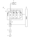
- FIG. 1 is a block diagram illustrating a power supply device for an electrolytic cell according to a first embodiment.
- FIG. 2 is a block diagram illustrating an example of a conversion circuit.
- FIG. 11 is a block diagram illustrating a first converter according to a second embodiment.
- 13 is a graph showing a schematic example of the operation of the electrolytic cell power supply device according to the third embodiment.
- FIG. 13 is a block diagram illustrating a power supply device for an electrolytic cell according to a fourth embodiment.
- FIG. 13 is a block diagram illustrating a power supply device for an electrolytic cell according to a fifth embodiment.
- FIG. 13 is a block diagram illustrating a power supply device for an electrolytic cell according to a sixth embodiment.
- 8(a) and 8(b) are timing charts showing an example of the operation of the power supply device for an electrolytic cell according to the sixth embodiment.
- FIG. 1 is a block diagram showing a schematic diagram of a power supply device for an electrolytic cell according to a first embodiment.
- the electrolytic cell power supply device 10 includes a first converter 11, a second converter 12, a storage element 14, and a control device 16.
- the electrolytic cell power supply device 10 is used in an electrolytic cell 2.
- the electrolytic cell 2 has an anode 2a and a cathode 2b.
- the electrolytic cell power supply device 10 supplies DC power between the anode 2a and the cathode 2b of the electrolytic cell 2, thereby causing the electrolytic cell 2 to perform electrolysis.
- the electrolytic cell 2 performs electrolysis in response to the supply of DC power from the electrolytic cell power supply device 10, thereby producing products such as hydrogen.
- the electrolytic cell 2 may further include, for example, an ion exchange membrane (diaphragm) disposed between the anode and the cathode.
- the electrolytic cell 2 may be configured in any way that has at least an anode 2a and a cathode 2b and is capable of performing electrolysis of an electrolyte by supplying DC power between the anode 2a and the cathode 2b.
- the electrolytic cell power supply device 10 is connected to the electrolytic cell 2 and also to the power system 4.
- the power system 4 is an AC power system.
- the electrolytic cell power supply device 10 is connected to the power system 4, for example, via a transformer 6.
- the power of the power system 4 is, for example, three-phase AC power.
- the power of the power system 4 is not limited to three-phase AC power, and may be single-phase AC power, etc.
- the first converter 11 is connected to the power system 4.
- the first converter 11 is connected to the power system 4, for example, via a transformer 6.
- the first converter 11 converts AC power supplied from the power system 4 into DC power.
- the first converter 11 is, for example, an AC-DC converter circuit.
- the storage element 14 stores the DC power output from the first converter 11.
- the storage element 14 is, for example, a capacitor or a secondary battery.
- the storage element 14 may be any element capable of storing the DC power output from the first converter 11.
- the second converter 12 converts the DC power stored in the storage element 14 into another DC power appropriate for the electrolytic cell 2, and supplies the converted DC power between the anode 2a and cathode 2b of the electrolytic cell 2.
- the second converter 12 is, for example, a DC-DC converter circuit.
- the second converter 12 has, for example, a plurality of conversion circuits 20 connected in parallel.
- FIG. 2 is a block diagram illustrating an example of a conversion circuit. As shown in FIG. 2, each of the multiple conversion circuits 20 has, for example, a pair of input terminals 20a, 20b, a pair of output terminals 20c, 20d, switching elements 21, 22, rectifying elements 23, 24, a capacitor 25, and a reactor 26.
- One input terminal, 20a is connected to the high-potential terminal of the storage element 14.
- the other input terminal, 20b is connected to the low-potential terminal of the storage element 14. This allows the DC power stored in the storage element 14 to be input to the conversion circuit 20 via the pair of input terminals 20a, 20b.
- the switching elements 21 and 22 have a pair of main terminals and a control terminal.
- the switching elements 21 and 22 also have an on state and an off state.
- the on state is a state in which a current flows between the pair of main terminals.
- the off state is a state in which the flow of current between the pair of main terminals is blocked.
- Each of the switching elements 21 and 22 switches between the on state and the off state depending on the voltage between the pair of main terminals and the voltage of the control terminal. Note that the off state is not limited to a state in which no current flows between the pair of main terminals, but may also be a state in which a weak current flows between the pair of main terminals within a range that does not affect the operation of the conversion circuit 20.
- the switching elements 21 and 22 are, for example, self-excited semiconductor switching elements such as IGBTs and MOSFETs. However, the switching elements 21 and 22 are not limited to this and may be any elements that can be arbitrarily switched between an on state and an off state.
- One main terminal of the switching element 21 is electrically connected to the input terminal 20a.
- the other main terminal of the switching element 21 is electrically connected to one main terminal of the switching element 22.
- the switching element 22 is connected in series with the switching element 21.
- the other main terminal of the switching element 22 is electrically connected to the input terminal 20b.
- the switching elements 21 and 22 are connected in series between the input terminals 20a and 20b. In other words, the switching element 21 is provided between the input terminal 20a and the switching element 22, and the switching element 22 is provided between the switching element 21 and the input terminal 20b.
- the rectifier element 23 is connected in anti-parallel to the switching element 21.
- the rectifier element 24 is connected in anti-parallel to the switching element 22.
- the rectifier elements 23 and 24 are, for example, diodes.
- the anodes of the rectifier elements 23 and 24 are electrically connected to the low-potential main terminals of the switching elements 21 and 22, and the cathodes of the rectifier elements 23 and 24 are electrically connected to the high-potential main terminals of the switching elements 21 and 22.
- the direction of the current flowing through the rectifier elements 23 and 24 (direction of rectification) is opposite to the direction of the current flowing through the switching elements 21 and 22.
- Capacitor 25 is provided between input terminals 20a and 20b. Capacitor 25, for example, suppresses fluctuations in the DC power input from storage element 14 to conversion circuit 20.
- One end of the reactor 26 is electrically connected to the connection point of the switching elements 21 and 22.
- the other end of the reactor 26 is electrically connected to one output terminal 20c.
- the other output terminal 20d is electrically connected to the input terminal 20b.
- Each of the multiple conversion circuits 20 has switching elements 21, 22, and converts DC power by switching the switching elements 21, 22.
- the conversion circuit 20 is, for example, a step-down chopper circuit.
- the conversion circuit 20 converts the DC power stored in the storage element 14 into another DC power corresponding to the electrolytic cell 2, for example, by switching the switching element 21.
- the second converter 12 has multiple conversion circuits 20 connected in parallel. This makes it possible to handle large DC power while suppressing increases in the allowable values of current and voltage required for the switching elements 21 and 22.
- the conversion circuit 20 also has, for example, multiple switching elements 21 connected in parallel, multiple switching elements 22 connected in parallel, multiple rectifier elements 23 connected in anti-parallel to each of the multiple switching elements 21, and multiple rectifier elements 24 connected in anti-parallel to each of the multiple switching elements 22. This makes it possible to further suppress increases in the allowable values of current and voltage required for the switching elements 21 and 22.
- the configuration of the conversion circuit 20 and the configuration of the second converter 12 are not limited to the above, and may be any configuration capable of converting the DC power stored in the storage element 14 into another DC power according to the electrolytic cell 2.
- the number of parallel connections of the conversion circuit 20 and the number of parallel connections of each switching element 21, 22 may be set appropriately depending on, for example, the magnitude of the DC power to be handled.
- the control device 16 controls the operation of the first converter 11 and the second converter 12.
- the control device 16 for example, generates a plurality of control signals corresponding to each of the switching elements 21, 22 of the plurality of conversion circuits 20, inputs each control signal to the control terminal of each switching element 21, 22, and controls the switching of each switching element 21, 22, thereby controlling the operation of the second converter 12.
- the control device 16 has a normal operation mode and a corrosion prevention operation mode.
- the normal operation mode is a mode in which, when the power system 4 is normal, the operation of the first converter 11 and the second converter 12 is controlled so that DC power for electrolysis is supplied to the electrolytic cell 2 based on AC power supplied from the power system 4.
- the control device 16 receives command values for the DC current and DC voltage to be supplied to the electrolytic cell 2 from, for example, a higher-level controller, and controls the operation of the first converter 11 and the second converter 12 so as to output a DC current and a DC voltage according to the received command values.
- the command values change, for example, according to the amount of product produced in the electrolytic cell 2. This makes it possible to produce the required amount of product in the electrolytic cell 2 based on the supply of DC power from the electrolytic cell power supply device 10 (second converter 12).
- the anticorrosion operation mode is a mode in which, during a power outage in the power grid 4, the operation of the second converter 12 is controlled so as to suppress the generation of a reverse current, which is a current in the opposite direction to normal electrolysis in the electrolytic cell 2, by supplying to the electrolytic cell 2 a DC power that is smaller than the DC power supplied to the electrolytic cell 2 in the normal operation mode, based on the DC power stored in the storage element 14.
- the power supply for the control device 16 during a power outage in the power grid 4 may be supplied from the storage element 14 or from another power source such as a battery.
- the control device 16 may have an auxiliary power source such as a battery to continue operation during a power outage in the power grid 4.
- the magnitude of the DC current supplied from the second converter 12 to the electrolytic cell 2 is set, for example, to about 1% (e.g., 0.5% to 5%) of the maximum value of the DC current supplied from the second converter 12 to the electrolytic cell 2 in the normal operation mode.
- the anticorrosion operation mode may be, for example, a state in which the magnitude of the DC current supplied by the electrolytic cell 2 is set close to zero, while a DC voltage of a predetermined magnitude is applied between the anode 2a and cathode 2b of the electrolytic cell 2.
- the control device 16 stops the operation of the first converter 11.
- the control device 16 stops the operation of the first converter 11, for example, by stopping the input of a control signal to the first converter 11.
- the control device 16 stops the operation of the first converter 11 by performing a so-called gate block.
- the electrolytic cell power supply device 10 further includes, for example, a measuring instrument (not shown).
- the measuring instrument measures, for example, the AC current and AC voltage of the power grid 4 and inputs the measurement results to the control device 16.
- the measuring instrument is a measuring instrument for detecting a power outage in the power grid 4.
- the control device 16 In the normal operation mode, the control device 16 detects a power outage in the power system 4 based on the measurement results of the measuring instruments, and switches from the normal operation mode to the anti-corrosion operation mode in response to the detection of the power outage. In the anti-corrosion operation mode, the control device 16 detects the recovery from a power outage in the power system 4 based on the measurement results of the measuring instruments, and switches from the anti-corrosion operation mode to the normal operation mode in response to the detection of the recovery from the power outage.
- control device 16 detects a power outage in the power system 4 and detects recovery from a power outage in the power system 4 is not limited to the above.
- the control device 16 may detect a power outage and recovery from a power outage, for example, based on a signal input from a higher-level controller.
- the method by which the control device 16 detects a power outage in the power system 4 and detects recovery from a power outage in the power system 4 may be any method that can appropriately detect a power outage in the power system 4 and recovery from a power outage.
- a "power outage” is not limited to a drop in the voltage of the power grid 4 that continues for a specified period of time or longer, but also includes momentary interruptions and momentary voltage drops in which the voltage of the power grid 4 drops temporarily for a short period of time, such as less than one minute.
- the control device 16 has a normal operation mode and an anti-corrosion operation mode, and switches from the normal operation mode to the anti-corrosion operation mode upon detection of a power outage.
- the electrolytic cell power supply device 10 can prevent the configuration of the equipment related to the electrolytic cell 2 from becoming more complicated compared to, for example, a case in which a corrosion prevention power supply is prepared separately from the electrolytic cell power supply device 10 and power is supplied to the electrolytic cell 2 from the corrosion prevention power supply in the event of a power outage. For example, it is possible to prevent the equipment from becoming larger and the costs from increasing.
- the electrolytic cell power supply device 10 can prevent the occurrence of reverse current with a simpler configuration.
- the operation of the first converter 11 is stopped in the anticorrosion operation mode.
- FIG. 3 is a block diagram illustrating a first converter according to the second embodiment. 3, the first converter 11 has a plurality of full-bridge-connected switching elements 30 and a plurality of rectifying elements 32 connected in anti-parallel to each of the plurality of switching elements 30.
- the first converter 11 has a plurality of full-bridge-connected switching elements 30 and a plurality of rectifying elements 32 connected in anti-parallel to each of the plurality of switching elements 30.
- components that are substantially the same in function and configuration as those in the first embodiment are denoted by the same reference numerals, and detailed description thereof will be omitted.
- the first converter 11 has six switching elements 30 connected in a three-phase full bridge configuration, and six rectifier elements 32 connected in anti-parallel to each of the six switching elements 30.
- the first converter 11 converts the AC power supplied from the power system 4 into DC power by rectifying the power using a plurality of rectifying elements 32.
- the plurality of rectifying elements 32 are, for example, diodes.
- the first converter 11 converts the AC power supplied from the power system 4 into DC power using, for example, a diode bridge circuit.
- the first converter 11 also converts the DC power stored in the storage element 14 into AC power by switching the multiple switching elements 30.
- the first converter 11 has the function of converting the AC power supplied from the power system 4 into DC power and supplying it to the storage element 14, and the function of converting the DC power stored in the storage element 14 into AC power and supplying it to the power system 4.
- the first converter 11 has a bidirectional conversion function of converting AC power to DC power and converting DC power to AC power.
- control device 16 controls the operation of the first converter 11 so as to supply only reactive power to the power grid 4 based on the DC power stored in the storage element 14.
- the first converter 11 has a bidirectional conversion function, and the control device 16 controls the operation of the first converter 11 so that it supplies only reactive power to the power grid 4 during the corrosion prevention operation mode.
- the control device 16 controls the operation of the first converter 11 so that it supplies only reactive power to the power grid 4 during the corrosion prevention operation mode.
- Whether to stop the operation of the first converter 11 during the anticorrosion operation mode or to operate the first converter 11 to supply only reactive power may be appropriately selected depending on the capacity of the storage element 14, the specifications of the power system 4, and the like. For example, it may be possible to switch between a mode in which the operation of the first converter 11 is stopped and a mode in which the first converter 11 is operated to supply only reactive power based on a signal input from the outside.
- FIG. 4 is a graph showing a schematic example of the operation of the power supply device for an electrolytic cell according to the third embodiment.
- FIG. 4 shows an example of a schematic diagram of the effective value of the AC voltage (receiving voltage) supplied from the power grid 4, the period of the anticorrosion operation mode, and the command value of the DC current (output current) supplied to the electrolytic cell 2.
- the control device 16 detects a power outage in the power system 4 based on the power receiving voltage of the power system 4 measured by a measuring instrument (not shown).
- the control device 16 detects a power outage in the power system 4 when the power receiving voltage of the power system 4 falls below the power outage determination level VL1.
- the control device 16 switches from the normal operation mode to the anticorrosion operation mode in response to the detection of a power outage in the power system 4.
- the control device 16 switches to the anticorrosion operation mode, it gradually reduces the magnitude of the DC power supplied to the electrolytic cell 2.
- the control device 16 gradually reduces the magnitude of the DC power supplied to the electrolytic cell 2, for example, by gradually reducing the command value of the DC current supplied to the electrolytic cell 2 from the level of the normal operation mode to the level of the anticorrosion operation mode. In other words, the control device 16 gradually reduces the magnitude of the DC current supplied to the electrolytic cell 2.
- the control device 16 When operating in the anti-corrosion operation mode, the control device 16 detects the recovery of the power system 4 from a power outage based on the power receiving voltage of the power system 4 measured by a measuring instrument (not shown). The control device 16 detects the recovery of the power system 4 from a power outage when the power receiving voltage of the power system 4 becomes equal to or higher than the recovery determination level VL2.
- the recovery determination level VL2 is set to a value greater than the power outage determination level VL1, for example. This makes it possible to prevent the control device 16 from detecting the occurrence of a power outage immediately after detecting the recovery from the power outage, for example.
- the control device 16 switches from the anti-corrosion operation mode to the normal operation mode in response to detection of recovery of the power system 4 from a power outage.
- the control device 16 switches to the normal operation mode, it gradually increases the magnitude of the DC power supplied to the electrolytic cell 2.
- the control device 16 gradually increases the magnitude of the DC power supplied to the electrolytic cell 2, for example, by gradually increasing the command value of the DC current supplied to the electrolytic cell 2 from the level of the anti-corrosion operation mode to the level of the normal operation mode. In other words, the control device 16 gradually increases the magnitude of the DC current supplied to the electrolytic cell 2.
- control device 16 gradually changes the magnitude of the DC power supplied to the electrolytic cell 2 when switching from the normal operation mode to the anticorrosion operation mode, and when switching from the anticorrosion operation mode to the normal operation mode. This makes it possible to suppress, for example, deterioration of the electrolytic cell 2 due to a sudden change in the DC power (DC current) supplied to the electrolytic cell 2.
- the capacity of the storage element 14 (the magnitude of the DC power stored in the storage element 14) is determined according to the energy consumption required to gradually change the magnitude of the DC power.
- the magnitude of the DC power supplied to the electrolytic cell 2 is gradually changed by continuously changing the command value for the DC current at a constant slope.
- the command value for the DC current is not limited to a continuous change, and may be changed in steps, for example.
- the control device 16 may gradually change the magnitude of the DC power supplied to the electrolytic cell 2, for example, by gradually changing the command value for the DC voltage.
- the method for gradually changing the magnitude of the DC power supplied to the electrolytic cell 2 is not limited to the above, and any method capable of gradually changing the magnitude of the DC power supplied to the electrolytic cell 2 may be used.
- FIG. 5 is a block diagram showing a schematic diagram of a power supply device for an electrolytic cell according to a fourth embodiment.
- the electrolytic cell power supply device 10 a has an emergency generator 40 , a rectifier 42 , switches 44 and 46 , and a transformer 48 .
- the emergency generator 40 is a generator for charging the storage element 14 in the event of a power outage in the power system 4.
- the power generated by the emergency generator 40 is, for example, AC power.
- the emergency generator 40 is, for example, an AC generator.
- the emergency generator 40 is, for example, an engine generator that generates power using fuel such as gasoline or gas.
- the start and stop of the emergency generator 40 is controlled, for example, by the control device 16.
- the rectifier 42 is a rectifier for initially charging the storage element 14 based on the AC power supplied from the power system 4.
- the rectifier 42 is, for example, a diode bridge circuit.
- the rectifier 42 for example, full-wave rectifies the AC power supplied from the power system 4 and supplies the rectified power to the storage element 14, thereby initially charging the storage element 14.
- the configuration of the rectifier 42 is not limited to the above, and any configuration that allows initial charging of the storage element 14 based on the AC power supplied from the power system 4 may be used.
- the rectifier 42 is connected to the power system 4, for example, via a switch 44 and a transformer 48.
- the opening and closing of the switch 44 is controlled, for example, by the control device 16.
- the control device 16 closes the switch 44 and charges the storage element 14 via the rectifier 42 to a level at which the first converter 11 and the second converter 12 can operate normally.
- the control device 16 opens the switch 44 and starts the operation of the first converter 11 and the second converter 12.
- the emergency generator 40 is connected to the storage element 14 via the rectifier 42.
- the emergency generator 40 generates AC power and supplies the generated AC power to the rectifier 42, thereby charging the storage element 14 via the rectifier 42.
- the switch 46 is provided between the emergency generator 40 and the rectifier 42.
- the emergency generator 40 is connected to the storage element 14, for example, via the switch 46 and the rectifier 42.
- the opening and closing of the switch 46 is controlled, for example, by the control device 16.
- the control device 16 stops the emergency generator 40 and opens the switch 46.
- the control device 16 switches from the normal operation mode to the anticorrosion operation mode in response to the detection of a power outage in the power system 4
- the control device 16 starts the operation of the emergency generator 40 and closes the switch 46 to charge the storage element 14 based on the power generated by the emergency generator 40 during a power outage in the power system 4.
- the control device 16 may detect the voltage of the storage element 14 in the anticorrosion operation mode, and charge the storage element 14 based on the power generated by the emergency generator 40 only when the voltage of the storage element 14 drops.
- the electrolytic cell power supply device 10a further includes an emergency generator 40. This allows the DC power stored in the storage element 14 to continue operation in the anticorrosion operation mode for a longer period of time, and thus allows deterioration of the electrolytic cell 2 due to the occurrence of reverse current to be suppressed for a longer period of time.
- the capacity of the storage element 14 is set so that the anticorrosion operation mode can be executed with the DC power stored in the storage element 14 for the startup time of the emergency generator 40. This makes it possible to prevent the storage element 14 from requiring excessive capacity. By reducing the capacity required for the storage element 14, it is possible to prevent the storage element 14 from becoming larger and the costs from increasing. It is possible to continue the anticorrosion operation mode for a long period of time while reducing the capacity of the storage element 14.
- the electrolytic cell power supply device 10a further includes a rectifier 42, and the emergency generator 40 supplies the generated AC power to the rectifier 42, thereby charging the storage element 14 via the rectifier 42.
- the emergency generator 40 supplies the generated AC power to the rectifier 42, thereby charging the storage element 14 via the rectifier 42.
- the storage element 14 is charged via the rectifier 42 for initial charging. This reduces the need to further add another rectifier, etc., even when an AC emergency generator 40 is used, and reduces the increase in the number of parts and additional costs.
- the power generated by the emergency generator 40 is not limited to AC power, and may be DC power.
- the emergency generator 40 may be a DC generator or a storage battery.
- the rectifier 42 may be omitted.
- the electrolytic cell power supply device 10a does not necessarily have to have the rectifier 42.
- FIG. 6 is a block diagram showing a schematic diagram of a power supply device for an electrolytic cell according to a fifth embodiment.
- the electrolytic cell power supply device 10 b further includes a first current sensor 51 and a second current sensor 52 .
- the first current sensor 51 is a sensor for detecting the DC current supplied from the second converter 12 to the electrolytic cell 2 in the normal operation mode.
- the electrolytic cell power supply device 10b has, for example, a plurality of first current sensors 51 corresponding to each of the plurality of conversion circuits 20.
- the plurality of first current sensors 51 detect the DC current supplied from each of the plurality of conversion circuits 20 to the electrolytic cell 2 in the normal operation mode.
- the plurality of first current sensors 51 input the detection results of the DC current to the control device 16.
- the control device 16 controls the operation of the second converter 12 based on the detection result of the first current sensor 51.
- the control device 16 controls the operation of each of the multiple conversion circuits 20 based on the detection result of each of the multiple first current sensors 51.
- the control device 16 controls the operation of each of the multiple conversion circuits 20 based on the detection result of each of the multiple first current sensors 51 so that a direct current corresponding to a current command value is output from each of the multiple conversion circuits 20.
- the second current sensor 52 is a sensor for detecting the DC current supplied from the second converter 12 to the electrolytic cell 2 in the anticorrosion operation mode.
- the second current sensor 52 is provided, for example, between the second converter 12 and the electrolytic cell 2.
- the second current sensor 52 is provided between the multiple conversion circuits 20 and the electrolytic cell 2.
- the second current sensor 52 detects, for example, the DC current after merging of the multiple conversion circuits 20 connected in parallel.
- the second current sensor 52 inputs the detection result of the DC current to the control device 16.
- the control device 16 controls the operation of the second converter 12 based on the detection result of the second current sensor 52.
- the control device 16 controls the operation of each of the multiple conversion circuits 20 based on the detection result of the second current sensor 52.
- the control device 16 controls the operation of each of the multiple conversion circuits 20 based on the detection result of the second current sensor 52 so that a direct current corresponding to a current command value is output from each of the multiple conversion circuits 20.
- control device 16 controls the operation of the second converter 12 based on the detection result of the first current sensor 51, and in the corrosion prevention operation mode, the control device 16 controls the operation of the second converter 12 based on the detection result of the second current sensor 52.
- the DC current supplied from the second converter 12 to the electrolytic cell 2 in the anticorrosion operation mode is a small current, approximately 1% of the maximum value of the DC current supplied from the second converter 12 to the electrolytic cell 2 in the normal operation mode.
- the same current sensor as that used in the normal operation mode may not be able to properly detect the magnitude of the DC current supplied from the second converter 12 to the electrolytic cell 2 in the anticorrosion operation mode.
- the electrolytic cell power supply device 10b is equipped with two types of current sensors: a first current sensor 51 and a second current sensor 52.
- the second current sensor 52 is, for example, a current sensor that can detect a smaller DC current than the first current sensor 51. This makes it possible to more appropriately detect the magnitude of the DC current supplied from the second converter 12 to the electrolytic cell 2 in the anticorrosion operation mode.
- the detection result of the second current sensor 52 makes it possible to more appropriately control the operation of the second converter 12 in the anticorrosion operation mode.
- first current sensors 51 are provided corresponding to the multiple conversion circuits 20, respectively.
- the first current sensor 51 is not limited to this, and a single first current sensor 51 may be provided between the second converter 12 and the electrolytic cell 2, similar to the second current sensor 52.
- FIG. 7 is a block diagram showing a schematic diagram of a power supply device for an electrolytic cell according to a sixth embodiment. As shown in FIG. 7, the electrolytic cell power supply device 10 c further includes a plurality of current sensors 60 .
- the multiple current sensors 60 are provided corresponding to each of the multiple conversion circuits 20.
- the multiple current sensors 60 detect the DC current supplied to the electrolytic cell 2 from each of the multiple conversion circuits 20.
- the multiple current sensors 60 input the detection results of the DC current to the control device 16.
- the control device 16 controls the operation of the second converter 12 based on the detection results of the multiple current sensors 60. More specifically, the control device 16 controls the operation of each of the multiple conversion circuits 20 based on the detection results of each of the multiple current sensors 60. For example, the control device 16 controls the operation of each of the multiple conversion circuits 20 based on the detection results of each of the multiple current sensors 60 so that a direct current corresponding to a current command value is output from each of the multiple conversion circuits 20.
- the configuration of the electrolytic cell power supply unit 10c is a configuration in which the second current sensor 52 of the configuration of the electrolytic cell power supply unit 10b in the above embodiment is omitted, and only multiple first current sensors 51 are provided.
- the control device 16 controls the operation of the second converter 12 based on the detection results of the multiple current sensors 60 in both the normal operation mode and the anticorrosion operation mode.
- the control device 16 operates each of the multiple conversion circuits 20 in the normal operation mode, and operates only some of the multiple conversion circuits 20 in the anticorrosion operation mode.
- the control device 16 operates each of the multiple conversion circuits 20 connected in parallel in the normal operation mode, and operates only one of the multiple conversion circuits 20 in the anticorrosion operation mode.
- the control device 16 operates only some of the multiple conversion circuits 20 in the anticorrosion operation mode. This allows current to be concentrated in the portion of the conversion circuits 20 that are operated in the anticorrosion operation mode. In this way, by concentrating current in only some of the conversion circuits 20 during the anticorrosion operation mode, the value of the current detected by the current sensor 60 can be increased, and it is possible to accurately detect minute currents in the anticorrosion operation mode even with the same current sensor 60 as in the normal operation mode. For example, this eliminates the need to separately provide a second current sensor 52 with high detection accuracy. This prevents an increase in the number of parts and allows operation in the anticorrosion operation mode to be achieved with a simpler configuration.
- FIG. 8(a) and 8(b) are timing charts showing an example of the operation of the power supply device for an electrolytic cell according to the sixth embodiment.
- Fig. 8(a) shows an example of the operation of the control device 16 in the normal operation mode
- Fig. 8(b) shows an example of the operation of the control device 16 in the anticorrosion operation mode.
- Figures 8(a) and 8(b) show schematic examples of the switching timing of the switching elements 21 provided in each of the multiple conversion circuits 20.
- the on/off state of the switching elements 21 in each conversion circuit 20 is represented by a High/Low signal. That is, the on state of the switching element 21 is represented by a High signal, and the off state of the switching element 21 is represented by a Low signal.
- the control device 16 controls the magnitude of DC power output from each conversion circuit 20, for example, by periodically switching the switching element 21 of each conversion circuit 20 on and off and appropriately changing the on time and off time of the switching element 21 of each conversion circuit 20.
- the control device 16 controls the magnitude of DC power output from each conversion circuit 20, for example, by performing PWM control.
- control device 16 performs control to shift the switching timing of each of the switching elements 21 of the multiple conversion circuits 20.
- the control device 16 shifts the on-timing of the PWM control of each of the switching elements 21 of the multiple conversion circuits 20 according to, for example, the number of multiple conversion circuits 20 connected in parallel.
- the control device 16 controls the switching frequency of the switching elements 21 of some of the multiple conversion circuits 20 to be higher than the switching frequency of each of the switching elements 21 of the multiple conversion circuits 20 in the normal operation mode.
- FIG. 8(b) shows an example in which only one of the multiple conversion circuits 20 is operated and the switching frequency of the switching element 21 of the one conversion circuit 20 is set to twice the switching frequency in the normal operation mode. Note that the switching frequency in the anticorrosion operation mode is not limited to twice, and may be any frequency higher than the switching frequency in the normal operation mode.
- control device 16 performs control to shift the switching timing of each of the switching elements 21 of the multiple conversion circuits 20 in the normal operation mode. This makes it possible to reduce the ripple superimposed on the output current in the normal operation mode.
- control device 16 controls the switching frequency of the switching elements 21 of some of the multiple conversion circuits 20 in the anticorrosion operation mode to be higher than the switching frequency of each of the switching elements 21 of the multiple conversion circuits 20 in the normal operation mode. This makes it possible to reduce the ripple superimposed on the output current even in the anticorrosion operation mode. Even when the number of conversion circuits 20 in operation is reduced, it is possible to prevent the ripple superimposed on the output current from increasing excessively. For example, a more stable direct current can be supplied to the electrolytic cell 2.
- a power supply device for an electrolytic cell that causes an electrolytic cell to perform electrolysis by supplying DC power between an anode and a cathode of the electrolytic cell, a first converter that converts AC power supplied from a power grid into DC power; a storage element for storing the DC power output from the first converter; a second converter that converts the DC power stored in the storage element into another DC power suitable for the electrolytic cell, and supplies the converted DC power between the anode and the cathode of the electrolytic cell;
- Appendix 7 a first current sensor for detecting a direct current supplied from the second converter to the electrolytic cell in the normal operation mode; a second current sensor for detecting a direct current supplied from the second converter to the electrolytic cell in the anticorrosion operation mode; Further equipped with 7.
- the second converter has a plurality of converter circuits connected in parallel; 8.
- Each of the plurality of conversion circuits has a switching element and performs conversion of DC power by switching the switching element; 9. The power supply device for an electrolytic cell as described in claim 8, wherein the control device performs control to shift the switching timing of the switching elements of each of the plurality of conversion circuits in the normal operation mode, and performs control to make the switching frequency of the switching elements of some of the plurality of conversion circuits higher than the switching frequency of the switching elements of each of the plurality of conversion circuits in the normal operation mode in the corrosion prevention operation mode.
- 2...electrolytic cell 2a...anode, 2a...cathode, 4...power system, 6...transformer, 10, 10a to 10c...power supply device for electrolytic cell, 11...first converter, 12...second converter, 14...storage element, 16...control device, 20...conversion circuit, 20a, 20b...input terminal, 20c, 20d...output terminal, 21, 22...switching element, 23, 24...rectifier element, 25...capacitor, 26...reactor, 30...switching element, 32...rectifier element, 40...emergency generator, 42...rectifier, 44, 46...switch, 48...transformer, 51...first current sensor, 52...second current sensor, 60...current sensor
Landscapes
- Chemical & Material Sciences (AREA)
- Engineering & Computer Science (AREA)
- Chemical Kinetics & Catalysis (AREA)
- Electrochemistry (AREA)
- Materials Engineering (AREA)
- Metallurgy (AREA)
- Organic Chemistry (AREA)
- Automation & Control Theory (AREA)
- Analytical Chemistry (AREA)
- Inorganic Chemistry (AREA)
- Inverter Devices (AREA)
- Electrolytic Production Of Non-Metals, Compounds, Apparatuses Therefor (AREA)
Priority Applications (3)
| Application Number | Priority Date | Filing Date | Title |
|---|---|---|---|
| JP2024559761A JP7772494B2 (ja) | 2022-11-22 | 2022-11-22 | 電解槽用電源装置 |
| PCT/JP2022/043119 WO2024111043A1 (ja) | 2022-11-22 | 2022-11-22 | 電解槽用電源装置 |
| US18/837,761 US20250146146A1 (en) | 2022-11-22 | 2022-11-22 | Electrolytic cell power supply device |
Applications Claiming Priority (1)
| Application Number | Priority Date | Filing Date | Title |
|---|---|---|---|
| PCT/JP2022/043119 WO2024111043A1 (ja) | 2022-11-22 | 2022-11-22 | 電解槽用電源装置 |
Publications (1)
| Publication Number | Publication Date |
|---|---|
| WO2024111043A1 true WO2024111043A1 (ja) | 2024-05-30 |
Family
ID=91195331
Family Applications (1)
| Application Number | Title | Priority Date | Filing Date |
|---|---|---|---|
| PCT/JP2022/043119 Ceased WO2024111043A1 (ja) | 2022-11-22 | 2022-11-22 | 電解槽用電源装置 |
Country Status (3)
| Country | Link |
|---|---|
| US (1) | US20250146146A1 (https=) |
| JP (1) | JP7772494B2 (https=) |
| WO (1) | WO2024111043A1 (https=) |
Cited By (1)
| Publication number | Priority date | Publication date | Assignee | Title |
|---|---|---|---|---|
| CN118825942A (zh) * | 2024-07-12 | 2024-10-22 | 北京雷动智创科技有限公司 | 一种具有反向电流抑制功能的电源及控制方法 |
Citations (2)
| Publication number | Priority date | Publication date | Assignee | Title |
|---|---|---|---|---|
| JPH02156099A (ja) * | 1988-12-08 | 1990-06-15 | Permelec Electrode Ltd | 直流電源回路 |
| JP2001026893A (ja) * | 1999-07-14 | 2001-01-30 | Toagosei Co Ltd | 塩化アルカリ電解槽の保護方法及び保護装置 |
Family Cites Families (10)
| Publication number | Priority date | Publication date | Assignee | Title |
|---|---|---|---|---|
| JPS54134342A (en) * | 1978-04-10 | 1979-10-18 | Toshiba Corp | Captive generator control system |
| JPH03293941A (ja) * | 1990-04-12 | 1991-12-25 | Toshiba Corp | 無停電電源装置 |
| JPH07242402A (ja) * | 1994-03-02 | 1995-09-19 | Sasakura Eng Co Ltd | 水電解式オゾン発生装置 |
| JP3513393B2 (ja) | 1998-06-16 | 2004-03-31 | 三菱電機株式会社 | 無停電電源装置 |
| JP2004064975A (ja) | 2002-07-31 | 2004-02-26 | Densei Lambda Kk | 無停電電源装置 |
| JP4069896B2 (ja) | 2004-04-01 | 2008-04-02 | 富士電機システムズ株式会社 | 無停電電源装置 |
| JP5366475B2 (ja) | 2008-08-20 | 2013-12-11 | 株式会社中央製作所 | 停電補償機能を備えためっき装置 |
| JP5746928B2 (ja) | 2011-08-23 | 2015-07-08 | 株式会社Nttファシリティーズ | 直流電源装置 |
| US20140097093A1 (en) | 2012-10-05 | 2014-04-10 | Miox Corporation | Transformerless On-Site Generation |
| KR102195169B1 (ko) * | 2019-04-25 | 2020-12-24 | (주)지필로스 | 입력전압 안정화를 위한 유효 및 무효전력 조정기능을 갖는 수전해 시스템 |
-
2022
- 2022-11-22 US US18/837,761 patent/US20250146146A1/en active Pending
- 2022-11-22 JP JP2024559761A patent/JP7772494B2/ja active Active
- 2022-11-22 WO PCT/JP2022/043119 patent/WO2024111043A1/ja not_active Ceased
Patent Citations (2)
| Publication number | Priority date | Publication date | Assignee | Title |
|---|---|---|---|---|
| JPH02156099A (ja) * | 1988-12-08 | 1990-06-15 | Permelec Electrode Ltd | 直流電源回路 |
| JP2001026893A (ja) * | 1999-07-14 | 2001-01-30 | Toagosei Co Ltd | 塩化アルカリ電解槽の保護方法及び保護装置 |
Cited By (1)
| Publication number | Priority date | Publication date | Assignee | Title |
|---|---|---|---|---|
| CN118825942A (zh) * | 2024-07-12 | 2024-10-22 | 北京雷动智创科技有限公司 | 一种具有反向电流抑制功能的电源及控制方法 |
Also Published As
| Publication number | Publication date |
|---|---|
| US20250146146A1 (en) | 2025-05-08 |
| JP7772494B2 (ja) | 2025-11-18 |
| JPWO2024111043A1 (https=) | 2024-05-30 |
Similar Documents
| Publication | Publication Date | Title |
|---|---|---|
| US9735619B2 (en) | Power conversion device | |
| JP5641144B2 (ja) | 電力変換装置 | |
| US8159850B2 (en) | Converter control device | |
| US6800963B2 (en) | Power controller, power generation system, and control method of power controller | |
| JP2013042627A (ja) | 直流電源制御装置および直流電源制御方法 | |
| JP2007157733A (ja) | 燃料電池電源装置 | |
| JP7272897B2 (ja) | 充放電制御装置およびそれを備えたバッテリ並びに直流給電システム | |
| KR20000048954A (ko) | 스위칭 모드 전력 공급기의 펄스 전력 공급기 | |
| US20210066951A1 (en) | Power supply apparatus | |
| WO2021261094A1 (ja) | 直流バス制御システム | |
| CN111106601A (zh) | 直流电压分布系统的控制 | |
| JP2017085892A (ja) | 蓄電池用変換装置、電力供給システムおよび電力供給制御方法 | |
| JP2011024294A (ja) | 電力変換回路の制御回路、および、この制御回路を備えた電力変換装置 | |
| US20070077467A1 (en) | Fuel cell system and method of correcting fuel cell current | |
| JP7772494B2 (ja) | 電解槽用電源装置 | |
| JPWO2003103126A1 (ja) | 電力変換装置 | |
| CN102044986A (zh) | 单元逆变器系统 | |
| JP4859932B2 (ja) | 瞬時電圧低下・停電対策機能を有する電力変換システムの制御装置および制御方法 | |
| WO2021200902A1 (ja) | 直流バス制御システム | |
| JPH11113191A (ja) | 無停電電源装置及びその充電制御方法 | |
| JPH0765851A (ja) | 直流出力燃料電池システムおよびその運転方法 | |
| CN112531864A (zh) | 混合能量存储系统及发电机逆变器系统 | |
| JP2003208913A (ja) | 電力制御装置、発電システム、電力制御装置の制御方法 | |
| US11539223B2 (en) | Charging/discharging apparatus | |
| US12316122B2 (en) | Direct-current power supply and distribution system |
Legal Events
| Date | Code | Title | Description |
|---|---|---|---|
| 121 | Ep: the epo has been informed by wipo that ep was designated in this application |
Ref document number: 22966453 Country of ref document: EP Kind code of ref document: A1 |
|
| WWE | Wipo information: entry into national phase |
Ref document number: 18837761 Country of ref document: US |
|
| WWE | Wipo information: entry into national phase |
Ref document number: 2024559761 Country of ref document: JP |
|
| WWP | Wipo information: published in national office |
Ref document number: 18837761 Country of ref document: US |
|
| NENP | Non-entry into the national phase |
Ref country code: DE |
|
| 122 | Ep: pct application non-entry in european phase |
Ref document number: 22966453 Country of ref document: EP Kind code of ref document: A1 |