WO2024101113A1 - 画像処理装置、画像処理方法、プログラム - Google Patents
画像処理装置、画像処理方法、プログラム Download PDFInfo
- Publication number
- WO2024101113A1 WO2024101113A1 PCT/JP2023/037971 JP2023037971W WO2024101113A1 WO 2024101113 A1 WO2024101113 A1 WO 2024101113A1 JP 2023037971 W JP2023037971 W JP 2023037971W WO 2024101113 A1 WO2024101113 A1 WO 2024101113A1
- Authority
- WO
- WIPO (PCT)
- Prior art keywords
- pixel
- polarization
- pixels
- polarization characteristics
- image processing
- Prior art date
- Legal status (The legal status is an assumption and is not a legal conclusion. Google has not performed a legal analysis and makes no representation as to the accuracy of the status listed.)
- Ceased
Links
Images


Classifications
-
- H—ELECTRICITY
- H04—ELECTRIC COMMUNICATION TECHNIQUE
- H04N—PICTORIAL COMMUNICATION, e.g. TELEVISION
- H04N25/00—Circuitry of solid-state image sensors [SSIS]; Control thereof
- H04N25/10—Circuitry of solid-state image sensors [SSIS]; Control thereof for transforming different wavelengths into image signals
-
- H—ELECTRICITY
- H04—ELECTRIC COMMUNICATION TECHNIQUE
- H04N—PICTORIAL COMMUNICATION, e.g. TELEVISION
- H04N25/00—Circuitry of solid-state image sensors [SSIS]; Control thereof
- H04N25/60—Noise processing, e.g. detecting, correcting, reducing or removing noise
- H04N25/68—Noise processing, e.g. detecting, correcting, reducing or removing noise applied to defects
Definitions
- This technology relates to an image processing device, an image processing method, and a program that estimates polarization characteristics based on a polarized image.
- the image processing device described in Patent Document 1 when a defect is detected in one of four polarization pixels whose polarization directions differ by 45 degrees, estimates the pixel value of the polarization pixel where the defect was detected based on the pixel values of the three polarization pixels where no defect was detected.
- the image processing device described above if a defect is detected in one of four polarization pixels whose polarization directions differ by 45 degrees, it is possible to estimate the pixel value of the polarization pixel in which the defect was detected.
- the image processing device described above for example, if a defect is detected in two or more of four polarization pixels whose polarization directions differ by 45 degrees, it is not possible to estimate the pixel value of the polarization pixel in which the defect was detected. Therefore, in the image processing device described above, if a defect is detected in two or more of four polarization pixels whose polarization directions differ by 45 degrees, it is not possible to estimate the polarization characteristics.
- This technology was developed in consideration of the above issues, and aims to estimate polarization characteristics regardless of the number of effective pixels.
- An image processing device includes an image acquisition unit that acquires a plurality of polarized images with different polarization directions, and a polarization characteristics estimation unit that detects the number of effective pixels for each pixel position based on the plurality of polarized images, and estimates polarization characteristics for pixel positions where the detected number of effective pixels is less than a threshold value based on polarization information of surrounding pixel positions. This enables the image processing device to estimate the polarization characteristics for pixel positions where the detected number of effective pixels is less than the threshold value.
- FIG. 1 is a block diagram showing an example of the configuration of an image processing device according to a first embodiment of the present technology
- 2 is a diagram showing an example of the configuration of a pixel array section of a polarization sensor
- FIG. 1A to 1C are diagrams illustrating schematic diagrams of polarized images in each polarization direction obtained by image acquisition processing.
- 11 is an explanatory diagram of a polarization characteristic estimation process.
- FIG. FIG. 4 is an explanatory diagram of a polarization information image forming process.
- 10 is a flowchart showing a flow of a polarization characteristics estimation process in the first embodiment.
- 13 is a flowchart showing a flow of an invalid pixel detection process.
- FIG. 13 is a diagram illustrating an example of peripheral pixel positions.
- FIG. 13 is a diagram illustrating an example of peripheral pixel positions.
- FIG. 13 is a diagram illustrating an example of peripheral pixel positions.
- FIG. 13 is a diagram illustrating an example of peripheral pixel positions.
- FIG. 13 is a diagram illustrating an example of peripheral pixel positions.
- FIG. 13 is a diagram illustrating an example of peripheral pixel positions.
- FIG. 13 is a diagram illustrating an example of peripheral pixel positions.
- 11A and 11B are diagrams illustrating an example of determining polarization characteristics used when interpolating pixel values.
- FIGS. 11A and 11B are diagrams illustrating an example of determining polarization characteristics used when interpolating pixel values.
- 11A and 11B are diagrams illustrating an example of determining polarization characteristics used when interpolating pixel values.
- FIG. 13 is a diagram illustrating an example of machine learning in a modified example.
- FIG. 13 is a diagram illustrating an example of machine learning in a modified example.
- FIG. 13 is a diagram illustrating an example of machine learning in a modified example.
- FIG. 1 is a block diagram showing an example of the configuration of an image processing device 1 according to a first embodiment of the present technology.
- the image processing device 1 includes a polarization sensor 2, an image acquisition unit 3, a first signal processing unit 4, a polarization characteristics estimation unit 5, a second signal processing unit 6, a memory unit 7, and a bus 8.
- the bus 8 is provided so that the image acquisition unit 3, the first signal processing unit 4, the polarization characteristics estimation unit 5, and the second signal processing unit 6 can each read and write data to the memory unit 7.
- the image acquisition unit 3, the first signal processing unit 4, the polarization characteristic estimation unit 5, and the second signal processing unit 6 may each be configured as hardware, or may be configured as software using a single piece of hardware. If configured as hardware, the image acquisition unit 3, the first signal processing unit 4, the polarization characteristic estimation unit 5, and the second signal processing unit 6 may each be configured as different signal processing circuits or computers. If configured as software, the image processing device 1 may be configured as a computer device such as a microcomputer having a CPU (Central Processing Unit), ROM (Read Only Memory), RAM (Random Access Memory), etc., and the CPU may execute a program stored in the ROM, etc. to function as the image acquisition unit 3, the first signal processing unit 4, the polarization characteristic estimation unit 5, and the second signal processing unit 6.
- a computer device such as a microcomputer having a CPU (Central Processing Unit), ROM (Read Only Memory), RAM (Random Access Memory), etc.
- the CPU may execute a program stored in the ROM, etc. to function as the image acquisition unit 3, the first signal processing
- the polarization sensor 2 is an image sensor that obtains a pixel value (brightness value) for each pixel in a specific polarization direction. Note that the image sensor referred to here means a sensor in which pixels having light receiving elements are arranged two-dimensionally.
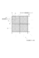
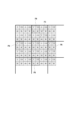
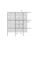
- FIG. 2 shows an example of the configuration of the pixel array section 2a of the polarization sensor 2.
- the pixel array section 2a is formed by arranging pixels Px, each of which has a photodiode as a light receiving element, in a two-dimensional manner.
- the pixel array section 2a has a color polarization pixel unit PC consisting of a plurality of polarization pixel units PP arranged two-dimensionally.
- the number of different polarization directions of light that can be received by the polarization pixel unit PP is arbitrary.
- the increment width of the polarization direction for each pixel Px in the polarization pixel unit PP is not limited to the 45 degree increments illustrated above, and other increment widths can be adopted.
- the color polarization pixel unit PC is a pixel unit in which a plurality of types of polarization pixel units PP, each of which selectively receives light of a different color component, are two-dimensionally arranged in a predetermined pattern.
- the color polarization pixel unit PC is configured such that a total of four polarization pixel units PP are arranged in a two-dimensional predetermined pattern: one polarization pixel unit PP that receives only red (R) light, two polarization pixel units PP that receive only green (G) light, and one polarization pixel unit PP that receives only blue (B) light.
- polarization pixel units PP that selectively receive red light are marked with diagonal lines running downward to the right
- polarization pixel units PP that selectively receive green light are marked with horizontal lines
- polarization pixel units PP that selectively receive blue light are marked with diagonal lines running downward to the left.
- the color polarization pixel unit PC of this example four polarization pixel units PP that receive red light, green light, and blue light are arranged in a Bayer type.
- the pixel array section 2a is configured by arranging color polarization pixel units PC as described above two-dimensionally. That is, the pixel array section 2a is configured by arranging multiple color polarization pixel units PC in the vertical direction (column direction) and horizontal direction (row direction).
- each pixel Px is configured to selectively receive light of a predetermined polarization direction and light of a predetermined color component (wavelength band).
- a polarizing filter and a color filter are disposed in front of the photodiode.
- the color filters are configured as optical bandpass filters that selectively transmit light in a predetermined wavelength band.
- an optical bandpass filter that selectively transmits red light is formed as a color filter.
- an optical bandpass filter that selectively transmits green light and an optical bandpass filter that selectively transmits blue light are formed as color filters, respectively.
- a polarizing filter is configured with a polarizer that selectively transmits linearly polarized light that vibrates in a specific direction (angle). Examples of polarizers include those that use a wire grid and those that have a crystal structure such as a photonic crystal.
- the image acquisition unit 3 receives the captured image obtained by the polarization sensor 2, extracts the luminance values of pixels that receive light in the same polarization direction from the captured image, and acquires a polarized image, which is an image for each polarization direction.
- FIG. 3A is a schematic diagram of a captured image (RAW image) output from the polarization sensor 2.
- FIG. 3B is a schematic diagram of polarized images in each polarization direction obtained by the image acquisition process.
- the captured image (RAW image) as shown in Fig. 3A is input from the polarization sensor 2.
- the captured image may be a still image or a moving image.
- the image acquisition section 3 performs an image acquisition process when writing an input captured image into the memory section 7 or when reading out the written captured image from the memory section 7 .
- the image acquisition unit 3 extracts pixel values between pixels Px that receive light with a polarization direction of 0 degrees, and generates a polarized image (hereinafter referred to as a "0 degree image”) consisting only of pixels that exhibit pixel values with a polarization direction of 0 degrees.
- the image acquisition unit 3 extracts the pixel values of pixels Px that receive light with a polarization direction of 45 degrees, and generates a polarized image (hereinafter referred to as a "45-degree image”) consisting only of pixels that exhibit pixel values with a polarization direction of 45 degrees.
- the image acquisition unit 3 extracts the pixel values of pixels Px that receive light with a polarization direction of 90 degrees, and generates a polarized image (hereinafter referred to as a "90-degree image") consisting only of pixels that exhibit pixel values with a polarization direction of 90 degrees.
- the image acquisition unit 3 extracts the pixel values of pixels Px that receive light with a polarization direction of 135 degrees, and generates a polarized image (hereinafter referred to as a "135-degree image”) consisting only of pixels that exhibit pixel values with a polarization direction of 135 degrees.
- pixels Px belonging to the same polarization pixel unit PP pixel values are obtained at the same pixel position in each of the polarization images of 0 degree image, 45 degree image, 90 degree image, and 135 degree image. Note that the pixel position represents the coordinates (Xi, Yj) in the polarization image.
- the first signal processing unit 4 performs image signal processing on each polarized image acquired by the image acquiring unit 3. Specifically, the image signal processing includes noise reduction processing, shading processing, demosaic processing, and the like. Here, the first signal processing unit 4 performs image signal processing on the polarized images for each polarization direction.
- the first signal processing unit 4 performs demosaic processing on each polarization image in which R, G, and B pixels are arranged in a Bayer array, for example. At this time, the first signal processing unit 4 can perform demosaic processing compatible with a general Bayer array.
- the arrangement of the polarization pixel units PP of each color is not limited to a Bayer pattern, and may be any arrangement according to a predetermined pattern that allows demosaic processing.
- each pixel position contains R, G, and B pixels with a polarization direction of 0 degrees, R, G, and B pixels with a polarization direction of 45 degrees, R, G, and B pixels with a polarization direction of 90 degrees, and R, G, and B pixels with a polarization direction of 135 degrees.
- the polarization characteristics estimation unit 5 performs a polarization characteristics estimation process to estimate the polarization characteristics for each color component at each pixel position based on the pixel values of the polarized image output by the first signal processing unit 4.
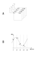
- FIG. 4 is an explanatory diagram of the polarization characteristic estimation process.
- Fig. 4A is a diagram showing a 0 degree image, a 45 degree image, a 90 degree image, and a 135 degree image
- Fig. 4B is a diagram showing a schematic diagram of polarization characteristics.
- fitting to a sine wave as shown in FIG. 4B is performed for each color component at each pixel position based on the 0 degree image, 45 degree image, 90 degree image, and 135 degree image.
- the polarization state of the incident light is represented by a sine wave with the vertical axis representing brightness (pixel value) and the horizontal axis representing the polarization direction. Therefore, for each polarized image, by fitting a sine wave based on the pixel value (brightness value) for each color component at each pixel position, the polarization characteristics for each color component at each pixel position can be estimated and calculated.
- the polarization characteristic f fitted to a sine wave can be expressed by any of the equations (1).
- f(Xi, Yj, B) ⁇ B ⁇ cos( ⁇ - ⁇ B ) + ⁇ B
- ⁇ indicates the amplitude
- ⁇ indicates the phase
- ⁇ indicates the offset.
- the subscript R indicates red
- the subscript G indicates green
- the subscript B indicates blue. Therefore, for example, ⁇ R indicates the amplitude of the polarization characteristic of red.
- the polarization characteristics estimation unit 5 calculates the amplitude ⁇ , phase ⁇ , and offset ⁇ for each color component at each pixel position by substituting pixel values (denoted as I0 , I45 , I90, and I135 in FIG. 4A) of four different polarization directions for each color component at each pixel position based on each of the polarization images of 0 degrees, 45 degrees, 90 degrees , and 135 degrees . This allows the polarization characteristics estimation unit 5 to estimate the polarization characteristics for each color component at each pixel position.
- the second signal processing unit 6 generates a polarization information image based on the polarization characteristics estimated by the polarization characteristics estimation unit 5.
- the second signal processing unit 6 also performs image processing such as gamma correction on the polarization information image.
- FIG. 5 is an explanatory diagram of the polarization information image forming process.
- the polarization characteristics estimation process estimates the polarization characteristics for each color component at each pixel position, making it possible to generate various polarization information images based on the polarization characteristics.
- examples of the polarization information images include a reflection-enhanced image, a polarization component image, a reflection-removed image, and an average image.
- the reflection-enhanced image is an image obtained by calculating a reflection-enhanced signal, which is calculated as the maximum value (Imax) of the polarization characteristic (sine wave) as shown in FIG. 5. Therefore, the second signal processing unit 6 can generate a reflection-enhanced image by calculating the maximum value of the sine wave for each color component at each pixel position.
- the reflection-removed image is an image obtained by calculating the reflection-removed signal, which is calculated as the minimum value (Imin) of a sine wave as shown in FIG. 5. Therefore, the second signal processing unit 6 can generate the reflection-removed image by calculating the minimum value of the sine wave for each color component at each pixel position.
- the polarization component image is an image obtained by calculating the polarization component signal, which is calculated as the amplitude of a sine wave as shown in FIG. 5. Therefore, the second signal processing unit 6 can generate a polarization component image by calculating the difference value (Imax-Ic) between the maximum value and average value (Ic) of the sine wave for each color component at each pixel position.
- the average image is an image obtained by calculating the average value of a sine wave, and the second signal processing unit 6 can generate the average image by calculating the average value (Ic) of the sine wave for each color component at each pixel position.
- polarization information images that can be generated by the second signal processing unit 6 are not limited to the four types exemplified above: reflection-enhanced image, polarization component image, reflection-removed image, and average image.
- each pixel Px receives light that has passed through a polarizing filter, so the pixel value becomes smaller or larger depending on the polarization direction due to the polarization characteristics. Therefore, the captured image obtained by the polarization sensor 2 is prone to saturated pixels and blocked-up pixels.
- a phase difference detection pixel having a pair of light receiving elements (diodes) into which pupil-divided light is incident within one pixel may be provided.
- the phase difference detection pixel is provided for calculating the defocus amount, and is not provided for obtaining a captured image. If the polarization characteristics are estimated based on the pixel values of invalid pixels such as saturated pixels, blocked-up pixels, and phase difference detection pixels that do not produce a captured image, the polarization characteristics cannot be estimated with high accuracy.
- the polarization characteristics estimation unit 5 detects the number of effective pixels for each color component at each pixel position based on multiple polarized images, and for color components for which the detected number of effective pixels is less than a threshold, estimates the polarization characteristics based on the polarization information of other color components at the same pixel position.
- pixels that need to be intentionally excluded such as saturated pixels, blacked-out pixels, and phase difference pixels (hereinafter referred to as defective pixels), i.e., pixels that cannot be used or are not suitable for calculations when estimating polarization characteristics, are collectively referred to as invalid pixels.
- pixels other than invalid pixels i.e., pixels that can be used for calculations when estimating polarization characteristics, are collectively referred to as valid pixels.
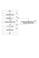
- FIG. 6 is a flowchart showing the flow of the polarization characteristics estimation process in the first embodiment.
- FIG. 7 is a flowchart showing the flow of the invalid pixel detection process.
- the polarization characteristics estimation unit 5 executes the polarization characteristics estimation process, it first performs an invalid pixel detection process in which all pixels (pixels resulting from a combination of color components and polarization directions) included in each pixel position are treated as target pixels, and it detects whether each target pixel is an invalid pixel (step S1).
- step S11 when the polarization characteristics estimation unit 5 starts the invalid pixel detection process, it determines whether the target pixel is a saturated pixel (step S11).
- the polarization characteristics estimation unit 5 determines whether the target pixel is a blocked-up pixel (step S12).
- the polarization characteristics estimation unit 5 determines whether the target pixel is a preset defective pixel (step S13).
- the polarization characteristics estimation unit 5 determines whether the target pixel is a noise pixel (step S14).
- the target pixel is determined to be a noise pixel if there is a difference of a predetermined value or more from the average pixel value of pixels of the same color component at the surrounding pixel positions. The surrounding pixel positions will be described later.
- the polarization characteristics estimation unit 5 detects the target pixel as a valid pixel.
- the polarization characteristics estimation unit 5 detects the target pixel as an invalid pixel.
- the polarization characteristics estimating unit 5 determines whether the number of valid pixels for each color component at each pixel position is greater than a threshold value Tn (step S2).
- the polarization characteristics can be expressed by equation (1).
- the amplitude ⁇ , phase ⁇ , and offset ⁇ are three unknowns. Therefore, if three pixels among the pixels in the four polarization directions of 0 degrees, 45 degrees, 90 degrees, and 135 degrees are valid pixels, the polarization characteristics estimation unit 5 can calculate the three unknowns using equation (1). Therefore, the threshold value Tn is set to a value (2) that allows the three unknowns to be calculated using equation (1).
- the polarization characteristics estimation unit 5 calculates the unknowns in equation (1), that is, the amplitude ⁇ , phase ⁇ , and offset ⁇ , by substituting the pixel values of the effective pixels into equation (1) and solving the simultaneous equation. This enables the polarization characteristics estimating unit 5 to estimate the polarization characteristics of the color component that is the calculation target (step S3).
- the polarization characteristics estimation unit 5 determines whether the number of valid pixels for each color component at each pixel position is two (threshold value Tn) (step S4). Here, it is determined whether two of the pixels of the four polarization directions of the same color component at the same pixel position are valid pixels.
- the polarization characteristics estimation unit 5 estimates the polarization characteristics based on the pixel values of the two effective pixels and the phase ⁇ of the other color component at the same pixel position (step S5).
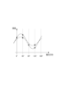
- FIG. 8 is a diagram explaining the polarization characteristic estimation process when there are two effective pixels.
- a black circle indicates the red pixel value (brightness value) at a given pixel position
- a black square indicates the green pixel value at that pixel position
- a solid line indicates the red polarization characteristic at that pixel position
- a dashed dotted line indicates the green polarization characteristic at that pixel position that will be estimated from this.
- red is detected as an effective pixel in any of the polarization directions of 0 degrees, 45 degrees, 90 degrees, and 135 degrees, and the polarization characteristics of red are also calculated in step S4. Therefore, it is assumed that the amplitude ⁇ R , phase ⁇ R , and offset ⁇ R in equation (1) are all calculated for red.
- the polarization characteristics estimation unit 5 can estimate the polarization characteristics when fitting the polarization characteristics with a sine wave even if there are only two effective pixels for a given color component at each pixel position.
- the polarization characteristics cannot be estimated.
- Second embodiment> Next, a second embodiment will be described.
- the polarization characteristics were estimated using the polarization characteristics of different color components at the same pixel position when there was an invalid pixel.
- the polarization characteristics are estimated using pixel values or polarization characteristics at surrounding pixel positions.
- the pixel values and polarization characteristics of the surrounding pixel positions are collectively referred to as polarization information.
- the polarization information may include other information related to polarization at the surrounding pixel positions in addition to the pixel values and polarization characteristics of the surrounding pixel positions.
- the first signal processing unit 4 performs image signal processing using image filters, such as noise reduction processing and shading processing, but does not perform demosaic processing. Therefore, in the polarized image for each polarization direction after image signal processing in the first signal processing unit 4, demosaic processing has not been performed, and therefore each pixel position contains only a pixel of one color component (either an R pixel, a G pixel, or a B pixel).
- the polarization characteristics estimation unit 5 performs polarization characteristics estimation processing using the polarized images for each polarization direction that have not been subjected to demosaicing.
- FIG. 9 is a flowchart showing the flow of the polarization characteristics estimation process in the second embodiment.
- the polarization characteristics estimation unit 5 executes the polarization characteristics estimation process, it first performs an invalid pixel detection process to detect invalid pixels at each pixel position (step S21). Note that the invalid pixel detection process is the same as in the first embodiment.
- the polarization characteristics estimation unit 5 determines whether the number of valid pixels at each pixel position is greater than a threshold value Tn (step S2). Note that the threshold value Tn is the same as in the first embodiment.
- step S22 if the number of valid pixels at each pixel position is greater than the threshold value Tn of 2 (Yes in step S22), i.e., if the number of valid pixels is 3 or 4, the polarization characteristics estimation unit 5 determines that fitting a sine wave is possible using equation (1) and makes the decision to use the pixel values of the valid pixels as is (step S23).
- the polarization characteristics estimating unit 5 interpolates the pixel values of the detected invalid pixels using the polarization information of the surrounding pixel positions (step S24).
- FIG. 10 to 15 are diagrams illustrating examples of peripheral pixel positions.
- a pixel group at a pixel position where the number of effective pixels is two or less is set as a target pixel group PS
- pixel groups adjacent to the target pixel group PS on the top, bottom, left and right sides are set as peripheral pixel groups PN.
- the image groups adjacent to the target pixel group PS on the top, bottom, left and right, and the four pixel groups adjacent in diagonal directions (top right, bottom right, top left and bottom left) are defined as surrounding pixel groups PN.
- FIG. 10 to 15 are diagrams illustrating examples of peripheral pixel positions.
- the pixel groups closest to it on the top, bottom, left and right are set as the surrounding pixel groups PN.
- the pixel groups closest to each other in the top, bottom, left, and right directions, and the four pixel groups closest to each other in diagonal directions (top right, bottom right, top left, bottom left), are defined as the surrounding pixel groups PN.
- a pixel group based on the same color polarization pixel unit PC as the target pixel group PS is defined as a peripheral pixel group PN.
- a group of pixels located in the same direction as the target pixel group PS with respect to the edge in the captured image is defined as a surrounding pixel group PN.
- the polarization characteristics estimation unit 5 determines the surrounding pixel group PN using one of the examples shown in Figures 10 to 15, and determines the pixel positions of the polarized image corresponding to the determined surrounding pixel group PN as the surrounding pixel positions.
- the polarization characteristics estimation unit 5 calculates the polarization characteristics of the surrounding pixel positions. Note that here, it is also possible to calculate only the polarization characteristics of surrounding pixel positions where the number of effective pixels is 3 or 4. In other words, it is also possible to exclude surrounding pixel positions where the number of effective pixels is 2 or less. This makes it possible to estimate the pixel values of invalid pixels using polarization characteristics with higher accuracy.
- the polarization characteristics estimation unit 5 determines the surrounding pixel positions to be used when interpolating the pixel values of the invalid pixels.
- Figures 16 to 18 are diagrams that explain an example of determining the surrounding pixel positions used when interpolating pixel values.
- multiple (two) polarization characteristics at the surrounding pixel positions are indicated by solid lines and dashed dotted lines.
- the pixel values of the effective pixels at pixel positions where the number of effective pixels is two or less are indicated by black squares.
- the polarization characteristics estimation unit 5 calculates the difference between the multiple polarization characteristics at the surrounding pixel positions and the pixel values of the effective pixels at the target pixel position.
- the polarization characteristics estimation unit 5 selects the surrounding pixel position corresponding to the polarization characteristics that have the smallest difference from the pixel value of the effective pixel at the target pixel position. In this case, the surrounding pixel position corresponding to the polarization characteristics indicated by the solid lines that are closest to the black square is selected. This results in the selection of the surrounding pixel position that best represents the polarization characteristics obtained from the effective pixels at the target pixel position.
- the pixel value of an effective pixel at one surrounding pixel position is indicated by a filled circle, and the pixel value of an effective pixel at another surrounding pixel position is indicated by a filled triangle.
- the pixel value of an effective pixel at a target pixel position is indicated by a filled square.
- the polarization characteristics estimation unit 5 calculates the difference between the pixel values of multiple effective pixels at each surrounding pixel position and the pixel value of the effective pixel at the target pixel position for the same polarization direction. Then, the polarization characteristics estimation unit 5 selects the surrounding pixel position that has the smallest sum of differences with the pixel values of the effective pixels at the target pixel position.
- the polarization characteristics estimation unit 5 selects the surrounding pixel position that includes a pixel value that has the smallest difference with the pixel value of the effective pixel at the target pixel position. In this case, the surrounding pixel position that includes the pixel indicated by the filled triangle is selected. This results in the selection of the surrounding pixel position that has a pixel whose value is closest to that of the effective pixel at the target pixel position.
- multiple polarization characteristics at surrounding pixel positions are shown by thin solid lines, thick solid lines, thin dashed dot lines, and thick dashed dot lines, respectively.
- the polarization characteristics estimation unit 5 selects, from the multiple polarization characteristics at the surrounding pixel positions, those that have many polarization characteristics that show a similar tendency.
- a similar tendency means, for example, that the phase ⁇ is included within a predetermined range. Therefore, here, the polarization characteristics shown by the thin solid lines, thick solid lines, and thick dashed dot lines show a similar tendency, so one of the surrounding pixel positions corresponding to these polarization characteristics is selected. This results in the selection of the surrounding pixel position that best represents the polarization characteristics around the target pixel position.
- the polarization characteristics estimation unit 5 selects one of the multiple surrounding pixel positions using any of the examples shown in Figures 16 to 18, it interpolates the pixel value of the invalid pixel based on the polarization information (polarization characteristics, pixel value) of the selected surrounding pixel position.
- the polarization characteristics estimation unit 5 extracts the offset ⁇ of the polarization characteristics at the selected surrounding pixel position. In addition, the polarization characteristics estimation unit 5 calculates the average value of the effective pixels at the target pixel position.
- the gain is calculated as the ratio between the value obtained by subtracting the offset ⁇ from the pixel value in the same polarization direction as the effective pixel at the selected peripheral pixel position, and the value obtained by subtracting the average value calculated from the pixel values of the effective pixels.
- the polarization characteristics estimation unit 5 calculates the pixel value of the invalid pixel by multiplying the pixel value in the same polarization direction as the invalid pixel at the selected surrounding pixel position by a gain and adding the average value.
- the polarization characteristics estimation unit 5 determines the pixel value of the invalid pixel to be the pixel value obtained by adding the saturation value to the pixel value in the same polarization direction as the invalid pixel at the selected surrounding pixel position.
- the polarization characteristics estimation unit 5 offsets the selected surrounding pixel positions so that the maximum value of the polarization characteristics of the selected surrounding pixel positions becomes 0, and then sets the pixel value of the invalid pixel in the same polarization direction as the invalid pixel in the offset polarization characteristics as the pixel value of the invalid pixel.
- the polarization characteristics estimation unit 5 After the pixel values of the invalid pixels are interpolated in this manner, the polarization characteristics estimation unit 5 performs demosaic processing on each polarization image using the pixel values of the valid pixels and the interpolated pixel values of the invalid pixels (step S25).
- the polarization characteristics estimation unit 5 calculates the polarization characteristics for each color component at each pixel position (step S26).
- the image processing device 1 is able to estimate the polarization characteristics at each pixel position by interpolating the pixel values of invalid pixels based on the polarization information of surrounding pixel positions, regardless of the number of invalid pixels at that pixel position.
- the image processing device 1 can generate a polarization information image regardless of the number of ineffective pixels.
- the image processing device 1 as an embodiment, giving two specific examples.
- the image processing device as an embodiment is not limited to the specific examples described above, and may adopt various modified configurations.
- the image processing device 1 has been described above as having a device configuration including the polarization sensor 2, the image processing device 1 may have a device configuration that does not include the polarization sensor 2.
- the polarization sensor 2 is configured to obtain a color image.
- the polarization sensor 2 may be configured to obtain a monochrome image.
- the pixel values of the invalid pixels may be interpolated based on the polarization information of the surrounding pixel positions corresponding to the surrounding pixel group PN shown in FIG. 10 or FIG. 11.
- the polarization sensor 2 has pixels with different polarization directions arranged two-dimensionally.
- the polarization sensor 2 may be configured to be replaceable with filters with different polarization directions, and the image acquisition unit 3 may acquire polarized images with different polarization directions by capturing polarized images for each of the different polarization directions.
- an invalid pixel detection process may be executed before the demosaic process, and if an invalid pixel is detected, the pixel value of the invalid pixel detected before the demosaic process may be interpolated using a known interpolation method such as linear interpolation.
- the method of interpolating the pixel values of invalid pixels in the second embodiment described above is not limited to the above example, and any other method may be used as long as it is possible to interpolate the pixel values of invalid pixels at the target pixel position using polarization information at surrounding pixel positions.
- the polarization properties estimation unit 5 may estimate (interpolate) the pixel values of invalid pixels by machine learning.
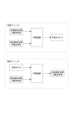
- the image processing device 1 includes a learning device as the polarization properties estimation unit 5, and in the learning phase, the learning device (polarization properties estimation unit 5) uses the pixel value of the target pixel position as teacher data and learns a prediction model for obtaining the teacher data from the pixel values of the surrounding pixel positions. Then, in the estimation phase, the learning device (polarization properties estimation unit 5) estimates (interpolates) the pixel values of the invalid pixels using the prediction model and the pixel values of the surrounding pixel positions.
- the learning device in the learning phase, not only valid pixels but also invalid pixels may be included among the pixels at the surrounding pixel positions.
- the learning device polarization characteristics estimation unit 5
- the learning device can estimate (interpolate) the pixel values of invalid pixels at the target pixel position using the prediction model and the pixel values at the surrounding pixel positions, even if invalid pixels are included among the pixels at the surrounding pixel positions.
- the polarization characteristics estimation unit 5 may estimate (interpolate) the polarization characteristics of the target pixel position including the invalid pixel by machine learning.
- the learning device uses the polarization characteristics of the target pixel position as teacher data and learns a prediction model for obtaining the teacher data from the polarization characteristics of the surrounding pixel positions. Then, in the estimation phase, the learning device estimates (interpolates) the polarization characteristics of the target pixel position including the invalid pixel by using the prediction model and the polarization characteristics of the surrounding pixel positions.
- the image processing device 1 includes an image acquisition unit 3 that acquires a plurality of polarized images with different polarization directions, and a polarization characteristics estimation unit 5 that estimates polarization characteristics based on polarization information of surrounding pixel positions for pixel positions where the number of effective pixels determined based on the plurality of polarized images is less than a threshold value.
- a threshold value a threshold value that estimates polarization characteristics based on polarization information of surrounding pixel positions for pixel positions where the number of effective pixels determined based on the plurality of polarized images is less than a threshold value.
- the image processing device 1 estimates the polarization characteristics for pixel positions where the number of effective pixels is less than the threshold value.
- the image processing device 1 is capable of estimating the polarization characteristics even if two or more of the pixels in the four polarization directions are invalid pixels. Therefore, the image processing device 1 can estimate the polarization characteristics regardless of the number of effective pixels.
- the polarized image is a color image
- the polarization characteristics estimation unit 5 estimates the polarization characteristics for color components in which the number of effective pixels at each pixel position obtained based on multiple polarized images is less than a threshold value, based on the polarization information of other color components at the same pixel position.
- the image processing device 1 is able to estimate the polarization characteristics of a color component having two invalid pixels using the polarization characteristics of other color components, even if the polarization characteristics are represented by a sine wave and there are two invalid pixels among the pixels in the four polarization directions.
- the polarization characteristics are represented by a sine wave
- the polarization characteristics estimation unit 5 estimates the polarization characteristics for a color component for which the number of effective pixels is less than a threshold value, using the phase of the polarization characteristics of other color components at the same pixel position. Since the phase ⁇ between different color components is identical or almost identical at the same pixel position, when the polarization characteristics are represented by a sine wave and there are two invalid pixels among the pixels in the four polarization directions, the image processing device 1 is able to accurately estimate the polarization characteristics of a color component having two invalid pixels by using the phase ⁇ of the other color components.
- the polarization characteristics estimating unit 5 interpolates the pixel values of the invalid pixels based on the polarization information of the surrounding pixel positions.
- the image processing device 1 can interpolate the pixel values of the invalid pixels based on the polarization information of the surrounding pixel positions, regardless of the number of valid pixels.
- the polarization characteristics estimating unit 5 estimates the polarization characteristics based on the pixel values of the valid pixels and the estimated pixel values of the invalid pixels. This allows the image processing device 1 to estimate the polarization characteristics using the estimated pixel values of the invalid pixels. At this time, since the pixel values of the invalid pixels are estimated based on the polarization information of the surrounding pixel positions, the image processing device 1 can accurately estimate the polarization characteristics for pixel positions where the number of valid pixels is less than a threshold value, regardless of the number of valid pixels.
- the polarization characteristics estimation unit 5 interpolates the pixel values of the invalid pixels based on the polarization information of the surrounding pixel positions that provide polarization characteristics with the smallest difference from the pixel values of the valid pixels. This allows the image processing device 1 to interpolate the pixel values of invalid pixels based on the polarization information of the surrounding pixel positions that provide polarization characteristics, among those obtained at multiple surrounding pixel positions, that are most similar to the polarization characteristics at a pixel position where the number of effective pixels is less than a threshold value. Therefore, the image processing device 1 can interpolate the pixel values of the invalid pixels with high precision.
- the polarization characteristics estimation unit 5 interpolates the pixel values of the invalid pixels based on the polarization information of the surrounding pixel positions that include a pixel value that has the smallest difference from the pixel value of a valid pixel at a pixel position where the number of valid pixels is less than a threshold value.
- This allows the image processing device 1 to interpolate the pixel value of an invalid pixel based on the polarization information of a surrounding pixel position that has a pixel value closest to the pixel value of a valid pixel at a pixel position where the number of valid pixels is less than a threshold value, among the pixel values at multiple surrounding pixel positions. Therefore, the image processing device 1 can interpolate the pixel values of the invalid pixels with high precision.
- the polarization characteristics estimation unit 5 interpolates the pixel values of the invalid pixels based on the polarization information of surrounding pixel positions at which polarization characteristics showing a similar tendency are obtained, among the polarization characteristics at the surrounding pixel positions. This allows the image processing device 1 to interpolate the pixel values of the invalid pixels based on the polarization information of the surrounding pixel positions that have polarization characteristics showing a similar tendency. Therefore, the image processing device 1 can interpolate the pixel values of the invalid pixels with high precision.
- the peripheral pixel positions are pixel positions adjacent to a pixel position in which the number of valid pixels is less than a threshold value. This allows the image processing device 1 to accurately interpolate the pixel value of the invalid pixel based on the polarization information at the closest surrounding pixel position that is likely to have similar polarization characteristics.
- the peripheral pixel positions are pixel positions that correspond to pixels of the same color component as and most adjacent to the pixel group of the pixel position having the number of valid pixels less than the threshold value. This allows the pixel value of an invalid pixel to be interpolated based on the polarization information of surrounding pixel positions of the same color component, so that the image processing device 1 can estimate the pixel value of the invalid pixel with high accuracy.
- the surrounding pixel positions are pixel positions corresponding to a group of pixels included in the same pixel unit as the group of pixels at a pixel position where the number of valid pixels is less than a threshold value, in a pixel unit in which pixels of different color components are arranged two-dimensionally in a predetermined pattern. This allows the pixel values of invalid pixels to be interpolated based on the polarization information of a group of pixels included in the same pixel unit, thereby allowing the image processing device 1 to estimate the pixel values of invalid pixels with high accuracy.
- the peripheral pixel positions are pixel positions that are located in the same direction with respect to the edge of the image as the pixel positions where the number of valid pixels is less than the threshold value. This makes it possible to interpolate the pixel values of invalid pixels based on the polarization information of a group of pixels located in the same direction relative to the edge, thereby enabling the image processing device 1 to estimate the pixel values of invalid pixels with high accuracy.
- the polarization characteristics estimation unit estimates pixel values of invalid pixels for pixel positions where the number of valid pixels is less than a threshold value by machine learning based on pixel values of surrounding pixel positions. This enables the image processing device 1 to easily estimate the pixel values of the invalid pixels.
- the surrounding pixels include invalid pixels. This allows the image processing device 1 to easily estimate the pixel value of an invalid pixel even if the surrounding pixels include invalid pixels.
- the image processing method acquires multiple polarized images with different polarization directions, and for a pixel position where the number of effective pixels determined based on the multiple polarized images is less than a threshold, estimates the polarization characteristics based on polarization information of surrounding pixel positions.
- the program also acquires multiple polarized images with different polarization directions, and causes the computer to execute a process of estimating polarization characteristics for pixel positions where the number of effective pixels determined based on the multiple polarized images is less than a threshold value, based on polarization information of surrounding pixel positions.
- Such a program can be recorded in advance in a HDD serving as a recording medium built into a device such as a computer device, or in a ROM within a microcomputer having a CPU.
- the software may be temporarily or permanently stored (recorded) on a removable recording medium such as a flexible disk, a CD-ROM (Compact Disc Read Only Memory), an MO (Magneto Optical) disk, a DVD (Digital Versatile Disc), a Blu-ray Disc (registered trademark), a magnetic disk, a semiconductor memory, a memory card, etc.
- a removable recording media may be provided as a so-called package software.
- Such a program can be installed in a personal computer or the like from a removable recording medium, or can be downloaded from a download site via a network such as a LAN (Local Area Network) or the Internet.
- LAN Local Area Network
- the present technology can also be configured as follows. (1) an image acquisition unit that acquires a plurality of polarized images with different polarization directions; a polarization characteristics estimation unit that estimates polarization characteristics for a pixel position where the number of effective pixels determined based on the plurality of polarization images is less than a threshold value, based on polarization information of surrounding pixel positions; An image processing device comprising: (2) the polarized image is a color image, The image processing device described in (1), wherein the polarization characteristics estimation unit estimates the polarization characteristics for a color component in which the number of effective pixels at each pixel position obtained based on the multiple polarization images is less than a threshold value, based on polarization information of other color components at the same pixel position.
- the polarization characteristic is represented by a sine wave
- the polarization characteristics estimation unit interpolates pixel values of invalid pixels based on polarization information of surrounding pixel positions for pixel positions where the number of valid pixels is less than a threshold value.
- the polarization characteristics estimation unit interpolates the polarization characteristics based on pixel values of valid pixels and estimated pixel values of invalid pixels for pixel positions where the number of valid pixels is less than a threshold value.
- the polarization characteristics estimation unit interpolates pixel values of invalid pixels based on polarization information at surrounding pixel positions at which polarization characteristics having the smallest difference from pixel values of valid pixels at pixel positions where the number of valid pixels is less than a threshold value are obtained.
- the polarization characteristics estimation unit interpolates pixel values of invalid pixels based on polarization information of surrounding pixel positions including pixel values having the smallest difference from pixel values of valid pixels at a pixel position where the number of valid pixels is less than a threshold.
- the polarization characteristics estimation unit interpolates pixel values of invalid pixels based on polarization information of surrounding pixel positions at which polarization characteristics showing a similar tendency are most obtained.
- peripheral pixel positions are pixel positions adjacent to a pixel position having a number of effective pixels less than a threshold value.
- the peripheral pixel positions are pixel positions that correspond to a pixel group having the same color component as a pixel group at a pixel position where the number of effective pixels is less than a threshold and that are most adjacent to the pixel group.
- the image processing device according to any one of (4) to (12), wherein the polarization characteristics estimation unit estimates pixel values of invalid pixels for pixel positions where the number of valid pixels is less than a threshold value by machine learning based on pixel values of surrounding pixel positions. (14) In the machine learning for estimating the pixel value of the invalid pixel, the invalid pixel is included in the peripheral pixel position. (15) Obtaining multiple polarized images with different polarization directions, The image processing method estimates polarization characteristics of a pixel position where the number of effective pixels determined based on the plurality of polarized images is less than a threshold value, based on polarization information of surrounding pixel positions.
- the program causes a computer to execute a process of estimating polarization characteristics based on polarization information of surrounding pixel positions for a pixel position where the number of effective pixels determined based on the plurality of polarized images is less than a threshold value.
Landscapes
- Engineering & Computer Science (AREA)
- Multimedia (AREA)
- Signal Processing (AREA)
- Color Television Image Signal Generators (AREA)
Priority Applications (1)
| Application Number | Priority Date | Filing Date | Title |
|---|---|---|---|
| JP2024557279A JPWO2024101113A1 (https=) | 2022-11-09 | 2023-10-20 |
Applications Claiming Priority (2)
| Application Number | Priority Date | Filing Date | Title |
|---|---|---|---|
| JP2022-179582 | 2022-11-09 | ||
| JP2022179582 | 2022-11-09 |
Publications (1)
| Publication Number | Publication Date |
|---|---|
| WO2024101113A1 true WO2024101113A1 (ja) | 2024-05-16 |
Family
ID=91032765
Family Applications (1)
| Application Number | Title | Priority Date | Filing Date |
|---|---|---|---|
| PCT/JP2023/037971 Ceased WO2024101113A1 (ja) | 2022-11-09 | 2023-10-20 | 画像処理装置、画像処理方法、プログラム |
Country Status (2)
| Country | Link |
|---|---|
| JP (1) | JPWO2024101113A1 (https=) |
| WO (1) | WO2024101113A1 (https=) |
Citations (3)
| Publication number | Priority date | Publication date | Assignee | Title |
|---|---|---|---|---|
| WO2018042815A1 (ja) * | 2016-08-31 | 2018-03-08 | ソニー株式会社 | 画像処理装置と画像処理方法 |
| JP2021122106A (ja) * | 2020-01-31 | 2021-08-26 | キヤノン株式会社 | 撮像装置、学習装置、撮像装置の制御方法、学習方法、学習済みモデルおよびプログラム |
| WO2022196477A1 (ja) * | 2021-03-19 | 2022-09-22 | 富士フイルム株式会社 | 画像データ処理装置、画像データ処理方法、画像データ処理プログラム及び撮像システム |
-
2023
- 2023-10-20 JP JP2024557279A patent/JPWO2024101113A1/ja active Pending
- 2023-10-20 WO PCT/JP2023/037971 patent/WO2024101113A1/ja not_active Ceased
Patent Citations (3)
| Publication number | Priority date | Publication date | Assignee | Title |
|---|---|---|---|---|
| WO2018042815A1 (ja) * | 2016-08-31 | 2018-03-08 | ソニー株式会社 | 画像処理装置と画像処理方法 |
| JP2021122106A (ja) * | 2020-01-31 | 2021-08-26 | キヤノン株式会社 | 撮像装置、学習装置、撮像装置の制御方法、学習方法、学習済みモデルおよびプログラム |
| WO2022196477A1 (ja) * | 2021-03-19 | 2022-09-22 | 富士フイルム株式会社 | 画像データ処理装置、画像データ処理方法、画像データ処理プログラム及び撮像システム |
Also Published As
| Publication number | Publication date |
|---|---|
| JPWO2024101113A1 (https=) | 2024-05-16 |
Similar Documents
| Publication | Publication Date | Title |
|---|---|---|
| US9179113B2 (en) | Image processing device, and image processing method, and program | |
| US20200184598A1 (en) | System and method for image demosaicing | |
| JP5672776B2 (ja) | 画像処理装置、および画像処理方法、並びにプログラム | |
| JP5872408B2 (ja) | カラー撮像装置及び画像処理方法 | |
| US8891866B2 (en) | Image processing apparatus, image processing method, and program | |
| JP5183880B2 (ja) | カラーフィルタおよび撮像素子 | |
| JP2020043435A (ja) | 画像処理装置、画像処理方法および画像処理プログラム | |
| JP6045767B1 (ja) | 撮像装置、画像取得方法、画像取得プログラムおよび記憶媒体 | |
| JP2006135919A (ja) | カラー撮像画像データの補間方法およびプログラム | |
| JP4717371B2 (ja) | 画像処理装置および画像処理プログラム | |
| JP4305071B2 (ja) | 信号補正方法 | |
| US12579607B2 (en) | Demosaicing method and apparatus for moire reduction | |
| KR101327790B1 (ko) | 영상 보간 방법 및 장치 | |
| WO2024101113A1 (ja) | 画像処理装置、画像処理方法、プログラム | |
| JP2014158267A (ja) | カラーフィルタ、撮像素子、画像処理装置および画像処理方法 | |
| JP2015122576A (ja) | 画素補間処理装置、撮像装置、プログラムおよび集積回路 | |
| JP3965460B2 (ja) | 単板カラーカメラの市松配列緑色信号等インタリーブの関係にある画素信号の補間方法 | |
| JP2009095012A (ja) | 補間方向の判定方法、色補間方法および色補間装置 | |
| CN106485754B (zh) | 鱼眼镜头的标定方法及设备 | |
| JP2021040212A (ja) | 画像処理装置、画像処理方法、及びプログラム | |
| WO2023153156A1 (ja) | 信号処理装置、プログラム | |
| Singh et al. | Joint chromatic aberration correction and demosaicking | |
| JP5195957B2 (ja) | カラーフィルタおよび撮像素子 | |
| JP2014192586A (ja) | 画像処理装置、画像処理方法及び画像処理プログラム | |
| US20060044428A1 (en) | Image pickup device and signal processing method |
Legal Events
| Date | Code | Title | Description |
|---|---|---|---|
| 121 | Ep: the epo has been informed by wipo that ep was designated in this application |
Ref document number: 23888464 Country of ref document: EP Kind code of ref document: A1 |
|
| WWE | Wipo information: entry into national phase |
Ref document number: 2024557279 Country of ref document: JP |
|
| NENP | Non-entry into the national phase |
Ref country code: DE |
|
| 122 | Ep: pct application non-entry in european phase |
Ref document number: 23888464 Country of ref document: EP Kind code of ref document: A1 |