WO2024100910A1 - 二酸化炭素還元装置および二酸化炭素削減量統合管理装置 - Google Patents
二酸化炭素還元装置および二酸化炭素削減量統合管理装置 Download PDFInfo
- Publication number
- WO2024100910A1 WO2024100910A1 PCT/JP2023/002845 JP2023002845W WO2024100910A1 WO 2024100910 A1 WO2024100910 A1 WO 2024100910A1 JP 2023002845 W JP2023002845 W JP 2023002845W WO 2024100910 A1 WO2024100910 A1 WO 2024100910A1
- Authority
- WO
- WIPO (PCT)
- Prior art keywords
- carbon dioxide
- amount
- cathode
- anode
- reduction device
- Prior art date
- Legal status (The legal status is an assumption and is not a legal conclusion. Google has not performed a legal analysis and makes no representation as to the accuracy of the status listed.)
- Ceased
Links
Images







Classifications
-
- C—CHEMISTRY; METALLURGY
- C25—ELECTROLYTIC OR ELECTROPHORETIC PROCESSES; APPARATUS THEREFOR
- C25B—ELECTROLYTIC OR ELECTROPHORETIC PROCESSES FOR THE PRODUCTION OF COMPOUNDS OR NON-METALS; APPARATUS THEREFOR
- C25B3/00—Electrolytic production of organic compounds
- C25B3/20—Processes
- C25B3/25—Reduction
- C25B3/26—Reduction of carbon dioxide
-
- C—CHEMISTRY; METALLURGY
- C25—ELECTROLYTIC OR ELECTROPHORETIC PROCESSES; APPARATUS THEREFOR
- C25B—ELECTROLYTIC OR ELECTROPHORETIC PROCESSES FOR THE PRODUCTION OF COMPOUNDS OR NON-METALS; APPARATUS THEREFOR
- C25B9/00—Cells or assemblies of cells; Constructional parts of cells; Assemblies of constructional parts, e.g. electrode-diaphragm assemblies; Process-related cell features
-
- C—CHEMISTRY; METALLURGY
- C25—ELECTROLYTIC OR ELECTROPHORETIC PROCESSES; APPARATUS THEREFOR
- C25B—ELECTROLYTIC OR ELECTROPHORETIC PROCESSES FOR THE PRODUCTION OF COMPOUNDS OR NON-METALS; APPARATUS THEREFOR
- C25B9/00—Cells or assemblies of cells; Constructional parts of cells; Assemblies of constructional parts, e.g. electrode-diaphragm assemblies; Process-related cell features
- C25B9/50—Cells or assemblies of cells comprising photoelectrodes; Assemblies of constructional parts thereof
Definitions
- the present invention relates to a carbon dioxide reduction device and a carbon dioxide reduction integrated management device.
- Artificial photosynthesis is a method of reducing carbon dioxide using light energy such as sunlight.
- a light reaction electrode and a dark reaction electrode are electrically connected, and the light reaction electrode uses light energy to generate protons and electrons from water, and the dark reaction electrode uses the generated protons and electrons to reduce carbon dioxide to carbon monoxide, formic acid, methane, and methanol.
- a light reaction electrode and a dark reaction electrode are electrically connected, and the light reaction electrode uses light energy to generate electrons, oxygen compounds, and water from hydroxide ions, and the dark reaction electrode supplies hydroxide ions to the light reaction electrode, and carbon dioxide is reduced to carbon monoxide, formic acid, methane, and methanol using the protons in the dark reaction tank and the electrons generated in the light reaction.
- Patent Document 1 describes a method in which only carbon dioxide is supplied to the cathode using a gas diffusion electrode.
- the only gas component supplied is carbon dioxide.
- the air that is the subject of this application is mainly composed of approximately 80% nitrogen and approximately 20% oxygen, with a dilute carbon dioxide concentration of approximately 400 ppm. It is necessary to selectively separate the dilute carbon dioxide in the air. Furthermore, if air is supplied directly to the cathode, the oxygen in the air will react with protons, inhibiting the reduction of carbon dioxide.
- the object of the present invention is to provide a carbon dioxide reduction device and a carbon dioxide reduction integrated management device that can directly reduce carbon dioxide in the atmosphere to hydrocarbons.
- the present invention provides a battery comprising an anode which is a light reaction electrode, a cathode which is a dark reaction electrode electrically connected to the anode and immersed in an electrolyte, and a carbon dioxide separation unit which separates carbon dioxide in the atmosphere in order to supply carbon dioxide to the electrolyte
- This carbon dioxide reduction device is characterized in that protons and electrons are generated from water at the anode using light energy, the protons and electrons generated at the anode are supplied to the cathode, and at the cathode, the protons and electrons generated at the anode react with the carbon dioxide separated in the carbon dioxide separation section to generate a carbon-containing compound.
- the carbon dioxide reduction device is characterized in that at the cathode, protons present in a cathode tank, electrons supplied from the anode, and the supplied carbon dioxide react with each other to generate a carbon-containing product, hydroxide ions generated from water at the cathode are supplied to the anode, and at the anode, the hydroxide ions generate water, an oxygen compound, and electrons using light energy, and the electrons are supplied to the cathode.
- the present invention relates to a carbon dioxide separation unit, (a) an oxygen removing means for removing oxygen from the atmosphere and then supplying the oxygen to the cathode; (b) a selective permeation means for selectively permeating carbon dioxide; (c) a dissolving means for dissolving carbon dioxide in an electrolytic solution in which the cathode is immersed and supplying the carbon dioxide to the cathode; It is preferable to have one of the above.
- the present invention provides a carbon dioxide reduction device and a carbon dioxide reduction integrated management device that can directly reduce atmospheric carbon dioxide to hydrocarbons.
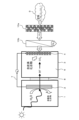
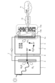
- FIG. 1 is a schematic diagram showing first and second embodiments of a carbon dioxide reduction device according to the present invention.
- FIG. FIG. 11 is a schematic diagram showing a third embodiment of a carbon dioxide reduction device of the present invention.
- FIG. 11 is a schematic diagram showing a fourth embodiment of the carbon dioxide reduction device of the present invention.
- FIG. 11 is a schematic diagram showing a fifth embodiment of the carbon dioxide reduction device of the present invention.
- FIG. 13 is a schematic diagram showing a sixth embodiment of the carbon dioxide reduction device of the present invention.
- FIG. 13 is a schematic diagram showing a seventh embodiment of the carbon dioxide reduction device of the present invention.
- FIG. 13 is a schematic diagram showing an eighth embodiment of the carbon dioxide reduction device of the present invention.
- FIG. 11 is a schematic diagram showing a third embodiment of a carbon dioxide reduction device of the present invention.
- FIG. 11 is a schematic diagram showing a fourth embodiment of the carbon dioxide reduction device of the present invention.
- FIG. 11 is a schematic diagram showing a fifth embodiment of
- FIG. 23 is a functional block diagram showing a control configuration of the eighth embodiment of the carbon dioxide reduction device of the present invention.
- FIG. 13 is a schematic diagram showing a ninth embodiment of the carbon dioxide reduction device of the present invention.
- FIG. 23 is a schematic diagram showing a carbon dioxide reduction device according to a tenth embodiment of the present invention.
- FIG. 15 is a schematic diagram showing an eleventh embodiment of the carbon dioxide reduction device of the present invention.
- FIG. 23 is a schematic diagram showing a carbon dioxide reduction device according to a twelfth embodiment of the present invention.
- FIG. 23 is a schematic diagram showing a thirteenth embodiment of the carbon dioxide reduction device of the present invention.
- FIG. 23 is a schematic diagram showing a fourteenth embodiment of the carbon dioxide reduction device of the present invention.
- FIG. 23 is a schematic diagram showing a fifteenth embodiment of the carbon dioxide reduction device of the present invention.
- Fig. 1 is a schematic diagram of the first embodiment of a carbon dioxide reduction device of the present invention.
- the carbon dioxide reduction device of this embodiment comprises an anode (light reaction electrode) 2 that generates protons (H + ) and electrons (e - ) from water by utilizing light energy such as sunlight, and a carbon dioxide separation section 10 that separates carbon dioxide in the atmosphere and supplies it directly to a cathode (dark reaction electrode) 4, the anode 2 and cathode 4 being electrically connected, and the protons and electrons generated at the anode 2 react with the carbon dioxide separated in the carbon dioxide separation section 10 at the cathode 4 to generate a carbon-containing compound, thereby reducing carbon dioxide in the atmosphere.
- anode light reaction electrode
- e - electrons
- the anode (light reaction electrode) cell 1 is equipped with an anode 2.
- the cathode (dark reaction electrode) cell 3 is equipped with a cathode 4.
- the cathode 4 is immersed in an electrolyte 6.
- the anode cell 1 contains water 5. Since the water in the anode cell is consumed in the electrode reaction, it is preferable to provide a supply means for supplying water to the anode cell.
- the anode 2 and cathode 4 are connected by a conductor 7.
- the water in the anode tank 1 and the electrolyte in the cathode tank 3 are separated by a proton exchange membrane 8.
- the proton exchange membrane may be, for example, a perfluorosulfonic acid proton exchange membrane.
- Carbon dioxide in the atmosphere 9 is supplied to the cathode 4 via a carbon dioxide separation section 10 .
- Carbon dioxide, protons, and electrons react on the cathode 4 to produce carbon-containing compounds (eg, ethylene, ethanol, methane, formic acid, etc.).
- a photocatalyst that absorbs light and excites electrons can be used for the anode 2.
- Examples of the photocatalyst include TiO2 , SrTiO3 , SrTiO2N , BaTaO2N , NaTaO3 , WO3 , ZnO, Fe2O3 , CuO, Ta2O5 , Bi2O3 , SnO2 , BiVO4 , and Y2Ti2O5S2 .
- the surface of the photocatalyst may be appropriately modified with a material that can be a promoter in order to promote the reaction.
- Representative promoter materials include, for example, Pt , Ru , Rh, and Au.
- the photocatalyst may also be supported by a substrate.
- the photocatalyst material may be a powder mixture, a compact, or a sheet.
- oxygen is generated as the oxygen compound
- hypochlorous acid and oxygen can be generated as the oxygen compounds.
- a material capable of reducing carbon dioxide using protons or ions is suitable for the cathode 4. Examples of materials that can be used include Au, Ag, Cu, Pt, Pd, Ni, Co, Fe, Mn, Ti, Cd, Zn, In, Ga, Pb, and Zn. At least one metal, metal oxide, or composite compound (complex compound, alloy, etc.) of these materials can be used.
- At least one metal, metal oxide, or composite compound (complex compound, alloy, etc.) of these materials applied to conductive carbon can be used as the cathode 4.
- an aqueous solution of potassium hydrogen carbonate, an aqueous solution of sodium hydrogen carbonate, an aqueous solution of potassium carbonate, an aqueous solution of sodium carbonate, an aqueous solution of potassium hydroxide, an aqueous solution of potassium chloride, or the like can be used.
- the carbon dioxide separation section 10 may be any section capable of concentrating carbon dioxide in the atmosphere.
- dilute carbon dioxide is separated from the atmosphere in the carbon dioxide separation section 10, and highly concentrated carbon dioxide is supplied to the cathode 4, improving the efficiency of carbon dioxide reduction. Furthermore, it is possible to prevent a decrease in reduction efficiency due to oxygen caused by directly supplying air to the cathode 4.
- the carbon dioxide separation unit 10 includes the following components as a carbon dioxide separation means: (a) an oxygen removing means for removing oxygen from the atmosphere and then supplying the oxygen to the cathode 4; (b) a selective permeation means for selectively permeating carbon dioxide; (c) a dissolving means for dissolving carbon dioxide in the electrolytic solution 6 in which the cathode 4 is immersed and supplying the carbon dioxide to the cathode 4;
- the device has one of the following features.
- Oxygen removal means for removing oxygen from the atmosphere and then supplying it to the cathode 4:
- Possible oxygen absorbers include porous materials that can selectively capture oxygen from the air (e.g., tetracyanoquinodimethane: https://scienceportal.jst.go.jp/newsflash/20100608_01/) and substances that selectively react with oxygen (iron-based oxygen absorbers, non-ferrous oxygen absorbers: https://www.mgc.co.jp/special/ageless/).
- Such oxygen absorbers are packed into the carbon dioxide separation section 10. When the air passes through the carbon dioxide separation section 10, oxygen in the air is removed, making it possible to suppress a decrease in the reduction reaction at the cathode 4 due to oxygen.
- the oxygen absorber can be packed into the carbon dioxide separation section 10 in the form of granules, honeycomb, or the like.
- the carbon dioxide separation section 10 preferably contains the oxygen absorber and is in the form of a sheet or an element made of a rolled up sheet having fine pores through which gas can pass.
- a selective permeation means for selectively permeating carbon dioxide As a carbon dioxide permeable membrane that can selectively permeate carbon dioxide in the atmosphere and supply it to the cathode 4, for example, a carbon dioxide separation membrane (https://cs2.toray.co.jp/news/toray/newsrrs01.nsf/0/4247C58AA8264EA2492586B700260B96?open) having a carbon thin film on the surface of a hollow fiber-shaped porous carbon fiber support or a zeolite membrane (https://www.ngk.co.jp/news/20211112_1.html) can be used.
- a carbon dioxide separation membrane https://cs2.toray.co.jp/news/toray/newsrrs01.nsf/0/4247C58AA8264EA2492586B700260B96?open
- a carbon dioxide separation membrane https://cs2.toray.co.jp/news/toray/newsrrs01.nsf
- the carbon dioxide permeable membrane serving as the selective permeation means can be provided in the carbon dioxide separation section 10 in the form of a hollow fiber membrane, or in the form of a flat membrane, i.e., a sheet or a rolled-up sheet element.
- the carbon dioxide permeable membrane in the form of a sheet or element and contacting the electrolyte 6 or the cathode 4, it is possible to prevent leakage of the electrolyte 6 from the cathode tank 3 to the outside of the tank while simultaneously supplying carbon dioxide to the cathode 4.
- a dissolving means for dissolving carbon dioxide in the electrolyte in which the cathode 4 is immersed and supplying the carbon dioxide to the cathode 4 The carbon dioxide separation section 10 is filled with an ion exchange resin, which converts carbon dioxide in the air into carbonate ions, bicarbonate ions, etc., and supplies the converted ions to the electrolyte 6 .
- a carbon dioxide reduction device according to a third embodiment of the present invention will be described with reference to FIG.
- the third embodiment is similar to the second embodiment, except that: (a) an oxygen removing means for removing oxygen from the atmosphere and then supplying the oxygen to the cathode 4; (b) a selective permeation means for selectively permeating carbon dioxide; This is an embodiment in which the above is combined.
- the air flows into the carbon dioxide separation section 10a (oxygen removal means) filled with an oxygen scavenger, and the oxygen in the air is removed.
- the gas containing nitrogen with oxygen removed and carbon dioxide flows into the carbon dioxide separation section 10b (selective permeation means) that selectively allows carbon dioxide to pass through, and the carbon dioxide is supplied to the cathode 4.
- Motor power is required for the carbon dioxide to move between the atmosphere 9 side and the carbon dioxide discharge side of the carbon dioxide separation unit 10b.
- a pressure difference can be used as a power source.
- the atmosphere may be pressurized to the pressure required for carbon dioxide separation in the upstream stage of the carbon dioxide separation unit 10a and then supplied.
- the carbon dioxide discharge side may be depressurized.
- a carbon dioxide reduction device according to a fourth embodiment of the present invention will be described with reference to FIG.
- the fourth embodiment is similar to the third embodiment described above, except that (a) an oxygen removing means for removing oxygen from the atmosphere and then supplying the oxygen to the cathode 4; (b) a selective permeation means for selectively permeating carbon dioxide;
- This embodiment has a carbon dioxide separation/catalyst electrode integrated section 100 integrated with a cathode 4a to which carbon dioxide is supplied.
- the air flows into the carbon dioxide separation section 10a, which is filled with an oxygen remover, and the oxygen in the air is removed.
- the gas containing nitrogen with oxygen removed and carbon dioxide flows into the carbon dioxide separation section 10b, which selectively allows carbon dioxide to pass through, and the carbon dioxide is supplied to the cathode 4a.
- the cathode 4a is an electrode catalyst having micropores through which carbon dioxide can diffuse. Because the cathode 4a is in contact with the carbon dioxide separation section 10b, the carbon dioxide flowing in from the carbon dioxide separation section 10b diffuses into the fine pores of the cathode 4a, and a reduction reaction to carbon-containing compounds proceeds due to the effect of protons in the electrolyte 6 that has permeated the cathode 4a and electrons from the conductive wire 7.
- a carbon dioxide reduction device according to a fifth embodiment of the present invention will be described with reference to FIG.
- the fifth embodiment is an example in which the carbon dioxide separation section 10 in FIG. 4 is provided with a carbon dioxide amount measuring means 11 for measuring the amount of carbon dioxide supplied to the cathode 4 .
- Typical examples of the carbon dioxide amount measuring means 11 include a non-dispersive infrared method that uses the infrared absorption property of carbon dioxide to measure the carbon dioxide concentration, a photoacoustic method, a solid electrolyte method, and a capacitance method.
- the sixth embodiment includes an anode/cathode reaction control unit 12 and a light energy intake adjustment unit 13 in addition to the components of the fifth embodiment.
- a side reaction other than the specified reaction may occur at cathode 4.
- a specified carbon-containing compound e.g., ethylene
- H/C molar ratio of 2 is the stoichiometric ratio.
- H/C ⁇ 2 proton deficiency relative to carbon dioxide
- the light energy intake adjustment unit 13 is equipped with, for example, a filter for adjusting the amount of light, and adjusts the amount of light energy absorbed into the anode 2 according to commands from the anode/cathode reaction control unit 12.
- the carbon dioxide separation section 10 is equipped with a carbon dioxide supply amount adjustment means 14 (see FIG. 8) that has the function of adjusting the amount of carbon dioxide permeation.
- the carbon dioxide supply amount adjustment means 14 adjusts the amount of carbon dioxide supplied to the cathode 4 according to commands from the anode/cathode reaction control section 12. For example, the adjustment may be made by widening or narrowing the opening area of the air intake section of the carbon dioxide separation section 10. Alternatively, the pressure or air volume for sending air to the carbon dioxide separation section 10 may be adjusted.
- a carbon dioxide reduction device according to a seventh embodiment of the present invention will be described with reference to FIG.
- the seventh embodiment is an embodiment in which the target carbon-containing compound in the anode/cathode reaction control section 12 of the sixth embodiment is ethylene.
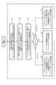
- the control flow in the seventh embodiment is shown in FIG.
- step 101 the anode/cathode reaction control unit 12 acquires the measurement result of the concentration (X) of carbon dioxide supplied to the cathode 4 by the carbon dioxide amount measuring means 11.
- X is the concentration in molar terms.
- step 103 the light energy intake adjustment unit 13 measures the maximum amount of light energy that can be supplied to the anode 2 and transmits it to the anode-cathode reaction control unit 12.
- the anode-cathode reaction control unit 12 calculates the amount of protons generated at the anode (P2).
- step 104 P2/P1 is calculated. Then, it is determined whether P2/P1 is equal to 1, greater than 1, or less than 1.
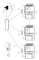
- the carbon dioxide reduction device 1000 according to the eighth embodiment includes, in addition to the carbon dioxide reduction devices according to the above-mentioned embodiments, a carbon dioxide reduction amount estimation unit 16 that estimates the amount of carbon dioxide reduction in the atmosphere.
- the carbon dioxide reduction device 1000 has a configuration in which the carbon dioxide reduction amount estimation unit 16 is added to the sixth embodiment, but the carbon dioxide reduction amount estimation unit 16 may be added to the other embodiments.
- the carbon dioxide reduction estimation unit 16 calculates the amount of carbon dioxide reduction in the atmosphere from the measured amount of carbon dioxide supplied from the atmosphere to the cathode 4 by the carbon dioxide separation unit 10, or from the amount of carbon-containing compounds produced by the reduction reaction of carbon dioxide at the cathode 4.
- the carbon dioxide reduction integrated management device 17 integrates and manages data on the amount of carbon dioxide reduction from multiple carbon dioxide reduction devices 1000.
- the carbon dioxide reduction integrated management device 17 includes a management unit 17a and a communication unit 17b.
- the management unit 17a includes a CPU (Central Processing Unit) and a storage unit such as a memory, and controls the carbon dioxide reduction integrated management device 17. Specifically, the management unit 17a manages data on the amount of carbon dioxide reduction estimated by the carbon dioxide reduction estimation unit 16 of the carbon dioxide reduction device 1000.
- the communication unit 17b is an interface for communicating with the carbon dioxide reduction device 1000, the carbon dioxide reduction display device 18, and the data center 19, and is connected to the management unit 17a.
- the management unit 17a transmits information on the amount of carbon dioxide reduction in the atmosphere or the amount of carbon-containing compounds generated in a specified period of time to the carbon dioxide reduction display device 18 via the communication unit 17b so that the owner of the carbon dioxide reduction device 1000 can confirm the information.
- the carbon dioxide reduction integrated management device 17 is connected online to the carbon dioxide reduction device 1000, the carbon dioxide reduction display device 18 (e.g., an app on a mobile terminal), and the data center 19 via a communication network N.
- the communication network N includes public networks such as telephone networks, mobile communication networks, ISDN, and packet switching networks, as well as computer networks such as LANs, WANs, and the Internet.
- the carbon dioxide reduction device 1000 has a control unit 20, a communication unit 21, a carbon dioxide separation unit 10, and a light energy intake adjustment unit 13.
- the control unit 20 has a CPU (Central Processing Unit) and a storage unit such as memory, and controls the carbon dioxide reduction device 1000 overall.
- the control unit 20 has an anode/cathode reaction control unit 12, and a light energy intake adjustment unit 13.
- the control unit 20 is connected to the carbon dioxide separation unit 10, a carbon dioxide reduction amount estimation unit 16, and a communication unit 21.
- the carbon dioxide separation unit 10 has a carbon dioxide supply amount adjustment means 14 and a carbon dioxide amount measurement means 11.
- the communication unit 21 is an interface for communicating with the carbon dioxide reduction amount integrated management device 17.
- the functions of the anode/cathode reaction control unit 12, carbon dioxide reduction amount estimation unit 16, carbon dioxide supply amount adjustment means 14, carbon dioxide amount measurement means 11, and light energy intake adjustment unit 13 are the same as those described in the above embodiment, so their description will be omitted.
- the owner of a carbon dioxide reduction device 1000 can check the amount of carbon dioxide that his or her device has reduced from the atmosphere over a specified period (hours, days, weeks, months, years, etc.) and the amount of carbon-containing compounds produced through the carbon dioxide reduction amount display device 18. It is also possible to check the amount of carbon dioxide reduced by all carbon dioxide reduction devices 1000 connected to the carbon dioxide reduction amount integrated management device 17. Furthermore, data on the amount of carbon dioxide reduced by multiple carbon dioxide reduction devices 1000 is stored in the data center 19, and analysis using this data is also possible.
- the carbon dioxide reduction device 1000 and carbon dioxide reduction integrated management device 17 of this embodiment make it possible to quantitatively grasp the reduction effect of carbon dioxide in the atmosphere.
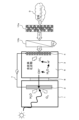
- FIG. 9 is a schematic diagram of the configuration of the ninth embodiment of the carbon dioxide reduction device of the present invention.
- the carbon dioxide reduction device according to this embodiment includes, for example, an anode (light reaction electrode) 2, a cathode (dark reaction electrode) 4, and a carbon dioxide separation unit 10 that separates carbon dioxide in the atmosphere and supplies it directly to the cathode (dark reaction electrode) 4.
- the anode 2 and the cathode 4 are electrically connected.
- the cathode tank 3 contains a cathode 4 immersed in an electrolytic solution 6.
- the electrolytic solution 6 is, for example, an aqueous solution of potassium bicarbonate or H2CO3 dissolved in water.
- protons (H + ) and HCO3- are generated according to the pH of the cathode tank solution. Also, protons (H+ ) and hydroxide ions ( OH- ) are generated from H2O according to the pH. Depending on the pH of the electrolytic solution 6, the water in the electrolytic solution generates protons (H + ) and hydroxide ions (OH ⁇ ) through equilibrium. The generated hydroxide ions (OH ⁇ ) move to the anode 2. Since water is consumed in the cathode chamber, it is preferable to provide a supply means for supplying water to the cathode chamber.
- the anode (light reaction electrode) 2 generates water (H 2 O), oxygen compounds (for example, oxygen), and electrons (e ⁇ ) from hydroxide ions (OH ⁇ ) supplied from the anode 2 by utilizing light energy such as sunlight.
- the carbon dioxide separation unit 10 separates carbon dioxide from the atmosphere and supplies it directly to the cathode (dark reaction electrode) 4 .
- a carbon-containing compound e.g., ethylene, ethanol, methane, formic acid, etc.
- the anode 2 and the cathode 4 are connected by a conductor 7.
- the water in the anode tank 1 and the electrolyte in the cathode tank 3 are separated by an anion exchange membrane 8b.
- the anion exchange membrane 8b has a separation function to prevent the solutions in the anode tank 1 and the cathode tank 3 from mixing, and also a function to supply hydroxide ions generated in the cathode tank 3 to the anode tank 1.
- anion exchange membranes include strongly basic anion exchange resins having quaternary amines as functional groups, and weakly basic anion exchange resins having primary to tertiary amines, such as Sustainion from Dioxide Materials and A-201 from Tokuyama (Sustainion(R) Reigns Over AEMION and Tokuyama A201
- the materials for the anode 2 and the cathode 4 those described in the first embodiment can be used. According to this embodiment, it is possible to improve the efficiency of carbon dioxide reduction since dilute carbon dioxide is separated from the atmosphere in the carbon dioxide separation unit 10 and highly concentrated carbon dioxide is supplied to the cathode 4. Furthermore, it is possible to prevent a decrease in reduction efficiency due to oxygen caused by directly supplying the atmosphere to the cathode 4.
- a carbon dioxide reduction device according to a tenth embodiment of the present invention will be described with reference to FIG.
- the tenth embodiment is the same as the ninth embodiment, except that (a) an oxygen removing means for removing oxygen from the atmosphere and then supplying the oxygen to the cathode 4; (b) a selective permeation means for selectively permeating carbon dioxide; This is an embodiment in which the above is combined.
- the atmospheric air is flowed into the carbon dioxide separation section 10a (oxygen removal means) filled with an oxygen scavenger, and oxygen in the atmospheric air is removed.
- the gas containing nitrogen from which oxygen has been removed and carbon dioxide flows into a carbon dioxide separation section 10 b (selective permeation means) that selectively allows carbon dioxide to permeate, and the carbon dioxide is supplied to the cathode 4 .
- Power is required for the carbon dioxide to move between the atmosphere 9 side and the carbon dioxide discharge side of the carbon dioxide separation unit 10b.
- a pressure difference can be used as a power source.
- the atmosphere may be pressurized to a pressure required for carbon dioxide separation in the upstream stage of the carbon dioxide separation unit 10a and then supplied.
- the carbon dioxide discharge side may be depressurized.
- the eleventh embodiment is the same as the tenth embodiment, except that (a) an oxygen removing means for removing oxygen from the atmosphere and then supplying the oxygen to the cathode 4; (b) a selective permeation means for selectively permeating carbon dioxide;
- This embodiment has a carbon dioxide separation/catalyst electrode integrated section 100 integrated with a cathode 4a to which carbon dioxide is supplied. First, the air flows into the carbon dioxide separation section 10a filled with an oxygen remover, and oxygen in the air is removed.
- the gas containing nitrogen from which oxygen has been removed and carbon dioxide flows into the carbon dioxide separation section 10b, which selectively allows carbon dioxide to permeate, and the carbon dioxide is supplied to the cathode 4a.
- the cathode 4a is an electrode catalyst having micropores through which carbon dioxide can diffuse. Because the cathode 4a is in contact with the carbon dioxide separation section 10b, the carbon dioxide flowing in from the carbon dioxide separation section 10b diffuses into the fine pores of the cathode 4a, and a reduction reaction to carbon-containing compounds proceeds due to the effect of protons in the electrolyte 6 that has permeated the cathode 4a and electrons from the conductive wire 7.
- An example of a method for ensuring the pressure difference required for carbon dioxide to move is shown below.
- the atmospheric air is pressurized to a pressure necessary for carbon dioxide separation in the carbon dioxide separation/catalyst electrode integrated section 100 .
- a carbon dioxide reduction device according to a twelfth embodiment of the present invention will be described with reference to FIG.
- the twelfth embodiment is an example in which the carbon dioxide separation section 10 in FIG. 12 is provided with a carbon dioxide amount measuring means 11 for measuring the amount of carbon dioxide supplied to the cathode 4 .
- Representative examples of the carbon dioxide amount measuring means 11 include a non-dispersive infrared method that measures the carbon dioxide concentration by utilizing the infrared absorbing property of carbon dioxide, a photoacoustic method, a solid electrolyte method, and a capacitance method.
- a carbon dioxide reduction device according to a thirteenth embodiment of the present invention will be described with reference to FIG.
- the thirteenth embodiment includes an anode/cathode reaction control unit 12 and a light energy intake adjustment unit 13 in addition to the components of the twelfth embodiment.
- Protons and hydroxide ions are generated by water equilibrium according to the pH of the cathode electrolyte 6.
- the generated hydroxide ions move to the anode through the anion exchange membrane, and water, oxygen compounds (e.g., oxygen), and electrons are generated using solar energy.
- a specified carbon-containing compound e.g., ethylene
- the protons at the cathode react with carbon dioxide, but there is a possibility that a side reaction other than the specified reaction may occur.
- ethylene C 2 H 4
- a H/C molar ratio of 2 is the stoichiometric ratio.
- H/C ⁇ 2 proton deficiency relative to carbon dioxide
- the light energy intake adjustment unit 13 includes, for example, a filter for adjusting the amount of light, and adjusts the amount of light energy taken in by the anode 2 in response to a command from the anode/cathode reaction control unit 12 .
- the carbon dioxide separation unit 10 is equipped with a carbon dioxide supply amount adjustment means 14 (see FIG. 8 ) that has a function of adjusting the amount of carbon dioxide permeation.
- the carbon dioxide supply amount adjustment means 14 adjusts the amount of carbon dioxide supplied to the cathode 4 in response to a command from the anode/cathode reaction control unit 12. For example, the adjustment may be made by widening or narrowing the opening area of the air intake part of the carbon dioxide separation unit 10. Alternatively, the pressure or air volume for sending air to the carbon dioxide separation unit 10 may be adjusted.
- a carbon dioxide reduction device according to a fourteenth embodiment of the present invention will be described with reference to FIG.
- the fourteenth embodiment is an embodiment in which the target carbon-containing compound in the anode/cathode reaction control section 12 of the thirteenth embodiment is ethylene.
- the control flow in the fourteenth embodiment is shown in FIG.
- the anode/cathode reaction control unit 12 acquires the measurement result of the concentration (X) of carbon dioxide supplied to the cathode 4 by the carbon dioxide amount measuring means 11.
- X is the concentration in molar terms.
- step 103a the light energy intake adjusting unit 13 measures the maximum amount of light energy that can be supplied to the anode, and transmits it to the anode/cathode reaction control unit 11.
- the anode/cathode reaction control unit 12 calculates the amount of hydroxide ions consumed at the anode (P2).
- step 104 P2/P1 is calculated. Then, it is determined whether P2/P1 is equal to 1, greater than 1, or less than 1.
- the carbon dioxide reduction device 1000b according to the fifteenth embodiment includes a carbon dioxide reduction amount estimation unit 16 that estimates the amount of carbon dioxide reduction in the atmosphere, in addition to the carbon dioxide reduction device according to the twelfth embodiment using the anion exchange membrane described above.
- the carbon dioxide reduction device 1000b has a configuration in which the carbon dioxide reduction amount estimation unit 16 is added to the twelfth embodiment, but the carbon dioxide reduction amount estimation unit 16 may be added to the ninth and subsequent embodiments.
- the carbon dioxide reduction estimation unit 16 calculates the amount of carbon dioxide reduction in the atmosphere from the measured amount of carbon dioxide supplied from the atmosphere to the cathode 4 by the carbon dioxide separation unit 10, or from the amount of carbon-containing compounds produced by the reduction reaction of carbon dioxide at the cathode 4.
- the carbon dioxide reduction amount integrated management device 17 integrates and manages data on the amount of carbon dioxide reduction from a plurality of carbon dioxide reduction devices 1000b.
- the carbon dioxide reduction amount integrated management device 17 includes a management unit 17a and a communication unit 17b (see FIG. 8).
- the management unit 17a includes a CPU (Central Processing Unit) and a storage unit such as a memory, and controls the carbon dioxide reduction amount integrated management device 17 in an integrated manner.
- CPU Central Processing Unit
- the management unit 17a manages data on the amount of carbon dioxide reduction estimated by the carbon dioxide reduction amount estimation unit 16 of the carbon dioxide reduction device 1000b.
- the communication unit 17b is an interface for communicating with the carbon dioxide reduction device 1000b, the carbon dioxide reduction amount display device 18, and the data center 19, and is connected to the management unit 17a.
- the management unit 17a transmits information on the amount of carbon dioxide reduction or the amount of carbon-containing compounds generated in the atmosphere during a predetermined period to the carbon dioxide reduction amount display device 18 via the communication unit 17b so that the owner of the carbon dioxide reduction device 1000b can confirm the information.
- the carbon dioxide reduction amount integrated management device 17 is connected online to the carbon dioxide reduction device 1000b, the carbon dioxide reduction amount display device 18 (for example, an application on a mobile terminal), and a data center 19 via a communication network N.
- the communication network N includes public networks such as a telephone network, a mobile communication network, an ISDN, and a packet switching network, and computer networks such as a LAN, a WAN, and the Internet.
- the carbon dioxide reduction device 1000b has a control unit 20, a communication unit 21, a carbon dioxide separation unit 10, and a light energy intake adjustment unit 13 (see FIG. 8).
- the control unit 20 has a CPU (Central Processing Unit) and a storage unit such as a memory, and controls the carbon dioxide reduction device 1000b in an integrated manner.
- CPU Central Processing Unit
- the control unit 20 has an anode/cathode reaction control unit 12 and a light energy intake adjustment unit 13.
- the control unit 20 is connected to the carbon dioxide separation unit 10, a carbon dioxide reduction amount estimation unit 16, and a communication unit 21.
- the carbon dioxide separation unit 10 has a carbon dioxide supply amount adjustment means 14 and a carbon dioxide amount measurement means 11.
- the communication unit 21 is an interface for communicating with the carbon dioxide reduction amount integrated management device 17.
- the owner of the carbon dioxide reduction device 1000b can check the amount of carbon dioxide reduced from the atmosphere and the amount of carbon-containing compounds produced by his/her device over a specified period (hours, days, weeks, months, years, etc.) through the carbon dioxide reduction amount display device 18. It is also possible to check the amount of carbon dioxide reduced by all of the carbon dioxide reduction devices 1000b connected to the carbon dioxide reduction amount integrated management device 17. Furthermore, data on the amount of carbon dioxide reduced by the multiple carbon dioxide reduction devices 1000b is stored in the data center 19, and analysis using the data is also possible. The carbon dioxide reduction device 1000b and the carbon dioxide reduction amount integrated management device 17 according to this embodiment make it possible to quantitatively grasp the reduction effect of carbon dioxide in the atmosphere.
- the present invention has been described above based on the embodiments, but the present invention is not limited to the above-described embodiments and includes various modified examples.
- the above-described embodiments have been described in detail to clearly explain the present invention, and are not necessarily limited to those having all of the configurations described. It is also possible to replace part of the configuration of one embodiment with the configuration of another embodiment, and it is also possible to add the configuration of another embodiment to the configuration of one embodiment. It is also possible to add, delete, or replace part of the configuration of each embodiment with other configurations.
- Carbon dioxide reduction amount estimation unit 17 Carbon dioxide reduction amount integrated management device 17a. Management unit 17b... Communication unit 18... Carbon dioxide reduction amount display device 19... Data center 20... Control unit 21... Communication unit 100... Carbon dioxide separation/catalyst electrode integrated unit 1000... Carbon dioxide reduction device 1000b... Carbon dioxide reduction device N... Communication network
Landscapes
- Chemical & Material Sciences (AREA)
- Organic Chemistry (AREA)
- Engineering & Computer Science (AREA)
- Chemical Kinetics & Catalysis (AREA)
- Electrochemistry (AREA)
- Materials Engineering (AREA)
- Metallurgy (AREA)
- Carbon And Carbon Compounds (AREA)
- Electrolytic Production Of Non-Metals, Compounds, Apparatuses Therefor (AREA)
Abstract
大気中の二酸化炭素を選択的に分離し、光エネルギーと水を利用して含炭素化合物に還元することを課題とする。二酸化炭素還元装置は、明反応電極であるアノード(2)と、アノード(2)と電気的に接続されており、かつ電解液(6)に浸漬された暗反応電極であるカソード(4)と、電解液(6)に二酸化炭素を供給するために、大気中の二酸化炭素を分離する二酸化炭素分離部(10)と、を備えており、アノード(2)において光エネルギー利用して電子を生成し、カソード(4)において、アノード(2)で生成した電子などを利用し、二酸化炭素分離部(10)で分離された二酸化炭素と反応して含炭素化化合物が生成されることを特徴とする。
Description
本発明は、二酸化炭素還元装置および二酸化炭素削減量統合管理装置に関する。
太陽光などの光エネルギーを利用した二酸化炭素還元方法として、人工光合成がある。例えば、明反応電極と暗反応電極を電気的に接続し、明反応電極では光エルギーを利用して水からプロトンと電子を生成し、暗反応電極では生成したプロトンと電子を利用して二酸化炭素を一酸化炭素やギ酸、メタン、メタノールに還元するものである。または、明反応電極と暗反応電極を電気的に接続し、明反応電極では光エルギーを利用して水酸化物イオンから電子と酸素化合物と水を生成し、暗反応電極では水酸化物イオンを明反応電極に供給し、暗反応槽中のプロトンと明反応で生成した電子を利用して二酸化炭素を一酸化炭素やギ酸、メタン、メタノールに還元するものである。
二酸化炭素のみをガス拡散電極を用いてカソードへ供給する方法が特許文献1に記載されている。
二酸化炭素のみをガス拡散電極を用いてカソードへ供給する方法が特許文献1に記載されている。
特許文献1の図1を参照すると、供給するガス成分は二酸化炭素のみである。一方、本願が対象としている大気は約80%の窒素、約20%の酸素が主成分であり、二酸化炭素濃度は400ppm程度と希薄である。大気中の希薄な二酸化炭素を選択的に分離することが必要となる。また、カソードに大気をそのまま供給すると大気中の酸素とプロトンが反応して二酸化炭素の還元が阻害される。
また、大気中の二酸化炭素削減量を定量的に把握することは地球温暖化対策、プラネタリーバウンダリーの観点でも重要である。
本発明の目的は、大気中の二酸化炭素を直接炭化水素に還元することが可能な二酸化炭素還元装置および二酸化炭素削減量統合管理装置を提供することにある。
上記課題を解決するため、本発明は、明反応電極であるアノードと、前記アノードと電気的に接続されており、かつ電解液に浸漬された暗反応電極であるカソードと、前記電解液に二酸化炭素を供給するために、大気中の二酸化炭素を分離する二酸化炭素分離部と、を備えており、
前記アノードにおいて光エネルギー利用して水からプロトンと電子を生成し、前記カソードへ前記アノードで生成したプロトンと電子が供給され、前記カソードにおいて、前記アノードで生成したプロトンと電子と前記二酸化炭素分離部で分離された二酸化炭素とが反応して含炭素化化合物が生成されることを特徴とする二酸化炭素還元装置である。
または、前記カソードにおいてカソード槽に存在するプロトンと前記アノードから供給された電子と前記供給二酸化炭素が反応して含炭素化物が生成し、前記カソードにおいて水から生成した水酸化物イオンは前記アノードへ供給され、前記アノードにおいて光エネルギー利用して前記水酸化物イオンが水と酸素化合物と電子とを生成し、前記電子は前記カソードへ供給されることを特徴とする二酸化炭素還元装置である。
さらに、本発明は、前記二酸化炭素分離部が、
(a)大気中から酸素を除去した後に前記カソードへ供給する酸素除去手段、
(b)二酸化炭素を選択的に透過させる選択的透過手段、
(c)二酸化炭素を前記カソードが浸漬された電解液に溶解させて前記カソードへ供給する溶解手段、
のいずれか一つを備えることが好ましい。
前記アノードにおいて光エネルギー利用して水からプロトンと電子を生成し、前記カソードへ前記アノードで生成したプロトンと電子が供給され、前記カソードにおいて、前記アノードで生成したプロトンと電子と前記二酸化炭素分離部で分離された二酸化炭素とが反応して含炭素化化合物が生成されることを特徴とする二酸化炭素還元装置である。
または、前記カソードにおいてカソード槽に存在するプロトンと前記アノードから供給された電子と前記供給二酸化炭素が反応して含炭素化物が生成し、前記カソードにおいて水から生成した水酸化物イオンは前記アノードへ供給され、前記アノードにおいて光エネルギー利用して前記水酸化物イオンが水と酸素化合物と電子とを生成し、前記電子は前記カソードへ供給されることを特徴とする二酸化炭素還元装置である。
さらに、本発明は、前記二酸化炭素分離部が、
(a)大気中から酸素を除去した後に前記カソードへ供給する酸素除去手段、
(b)二酸化炭素を選択的に透過させる選択的透過手段、
(c)二酸化炭素を前記カソードが浸漬された電解液に溶解させて前記カソードへ供給する溶解手段、
のいずれか一つを備えることが好ましい。
本発明によれば、大気中の二酸化炭素を直接炭化水素に還元することが可能な二酸化炭素還元装置および二酸化炭素削減量統合管理装置を提供することができる。
以下、本発明の二酸化炭素還元装置の実施の形態について図面を用いて説明する。
[第1の実施の形態]
本発明の第1の実施の形態について図1を用いて説明する。図1は本発明の二酸化炭素還元装置の第1の実施の形態の概略構成図である。
本実施形態に係る二酸化炭素還元装置は、例えば太陽光などの光エネルギーを利用して水からプロトン(H+)と電子(e-)を生成するアノード(明反応電極)2と、大気中の二酸化炭素を分離してカソード(暗反応電極)4へ直接供給する二酸化炭素分離部10とを備え、アノード2とカソード4は電気的に接続され、カソード4ではアノード2で生成したプロトンと電子と二酸化炭素分離部10で分離された二酸化炭素との反応により含炭素化化合物を生成する、ことにより大気中の二酸化炭素を削減することを特徴としている。
本発明の第1の実施の形態について図1を用いて説明する。図1は本発明の二酸化炭素還元装置の第1の実施の形態の概略構成図である。
本実施形態に係る二酸化炭素還元装置は、例えば太陽光などの光エネルギーを利用して水からプロトン(H+)と電子(e-)を生成するアノード(明反応電極)2と、大気中の二酸化炭素を分離してカソード(暗反応電極)4へ直接供給する二酸化炭素分離部10とを備え、アノード2とカソード4は電気的に接続され、カソード4ではアノード2で生成したプロトンと電子と二酸化炭素分離部10で分離された二酸化炭素との反応により含炭素化化合物を生成する、ことにより大気中の二酸化炭素を削減することを特徴としている。
アノード(明反応電極)槽1にはアノード2が備えられている。カソード(暗反応電極)槽3にはカソード4が備えられている。また、カソード槽3ではカソード4は電解液6に浸漬されている。アノード槽1には水5が入っている。アノード槽の水は、電極反応で消費されるため、水をアノード槽に供給する供給手段を備えていることが好ましい。
アノード2とカソード4は導線7で繋がっている。またアノード槽1の水とカソード槽3の電解液はプロトン交換膜8で隔離されている。
アノード2に光エネルギーが照射されると水の光分解によりプロトンと電子が生じる。電子は導線7を通じてカソード4へ供給される。プロトンはプロトン交換膜8を介してカソード槽3の電解液6へ供給される。
プロトン交換膜は、例えば、パーフルオロスルホン酸プロトン交換膜が利用できる。
プロトン交換膜は、例えば、パーフルオロスルホン酸プロトン交換膜が利用できる。
大気9中の二酸化炭素は二酸化炭素分離部10を介してカソード4へ供給される。
カソード4上で二酸化炭素とプトロンと電子の反応により含炭素化合物(例えば、エチレン、エタノール、メタン、ギ酸など)が生成する。
アノード2には、光を吸収して電子が励起する光触媒を用いることができる。光触媒としては、TiO2、SrTiO3、SrTiO2N、BaTaO2N、NaTaO3、WO3、ZnO、Fe2O3、CuO、Ta2O5、Bi2O3、SnO2、BiVO4、Y2Ti2O5S2などが挙げられる。反応を促進させるためにその表面に助触媒となり得る材料を適宜修飾しても良い。代表的な助触媒材料として、例えばPt、Ru、Rh、Au等がある。また光触媒は基材によって支持されていてもよい。光触媒材料は、粉末の混合体、圧粉体、シート状でもよい。
アノード槽の電解液として、例えば純水を用いると酸素化合物として酸素が生成し、塩化ナトリウム水溶液を用いると酸素化合物として次亜塩素酸と酸素が生成可能である。
カソード4には、二酸化炭素をプロトンやイオンを用いて還元できる材料が適している。材料例として、Au、Ag、Cu、Pt、Pd、Ni、Co、Fe、Mn、Ti、Cd、Zn、In、Ga、Pb、Znなどを用いることができる。これらの材料の少なくとも一つの金属、金属酸化物、複合化合物(錯体化合物、合金など)を用いることができる。また、これらの材料の少なくとも一つの金属、金属酸化物、複合化合物(錯体化合物、合金など)を導電性カーボンに塗布したものをカソード4として用いても良い。
カソード槽3の電解液6としては、例えば、炭酸水素カリウム水溶液、炭酸水素ナトリウム水溶液、炭酸カリウム水溶液、炭酸ナトリウム水溶液、水酸化カリウム水溶液、塩化カリウム水溶液などを用いることができる。
二酸化炭素分離部10は、大気中の二酸化炭素を濃縮できるものであればよい。
カソード4上で二酸化炭素とプトロンと電子の反応により含炭素化合物(例えば、エチレン、エタノール、メタン、ギ酸など)が生成する。
アノード2には、光を吸収して電子が励起する光触媒を用いることができる。光触媒としては、TiO2、SrTiO3、SrTiO2N、BaTaO2N、NaTaO3、WO3、ZnO、Fe2O3、CuO、Ta2O5、Bi2O3、SnO2、BiVO4、Y2Ti2O5S2などが挙げられる。反応を促進させるためにその表面に助触媒となり得る材料を適宜修飾しても良い。代表的な助触媒材料として、例えばPt、Ru、Rh、Au等がある。また光触媒は基材によって支持されていてもよい。光触媒材料は、粉末の混合体、圧粉体、シート状でもよい。
アノード槽の電解液として、例えば純水を用いると酸素化合物として酸素が生成し、塩化ナトリウム水溶液を用いると酸素化合物として次亜塩素酸と酸素が生成可能である。
カソード4には、二酸化炭素をプロトンやイオンを用いて還元できる材料が適している。材料例として、Au、Ag、Cu、Pt、Pd、Ni、Co、Fe、Mn、Ti、Cd、Zn、In、Ga、Pb、Znなどを用いることができる。これらの材料の少なくとも一つの金属、金属酸化物、複合化合物(錯体化合物、合金など)を用いることができる。また、これらの材料の少なくとも一つの金属、金属酸化物、複合化合物(錯体化合物、合金など)を導電性カーボンに塗布したものをカソード4として用いても良い。
カソード槽3の電解液6としては、例えば、炭酸水素カリウム水溶液、炭酸水素ナトリウム水溶液、炭酸カリウム水溶液、炭酸ナトリウム水溶液、水酸化カリウム水溶液、塩化カリウム水溶液などを用いることができる。
二酸化炭素分離部10は、大気中の二酸化炭素を濃縮できるものであればよい。
本実施形態によれば、二酸化炭素分離部10で大気中から希薄な二酸化炭素が分離され、高濃度化された二酸化炭素がカソード4に供給されるため、二酸化炭素の還元効率を向上できる。さらに、大気を直接カソード4に供給することにより生じる酸素による還元効率の低下も防止できる。
[第2の実施の形態]
本発明の二酸化炭素還元装置の第2の実施の形態について図1を用いて説明する。
第2の実施の形態では、二酸化炭素分離部10は、二酸化炭素の分離手段として、
(a)大気中から酸素を除去した後にカソード4へ供給する酸素除去手段、
(b)二酸化炭素を選択的に透過させる選択的透過手段、
(c)二酸化炭素をカソード4が浸漬された電解液6に溶解させてカソード4へ供給する溶解手段、
のいずれか一つを備える。
本発明の二酸化炭素還元装置の第2の実施の形態について図1を用いて説明する。
第2の実施の形態では、二酸化炭素分離部10は、二酸化炭素の分離手段として、
(a)大気中から酸素を除去した後にカソード4へ供給する酸素除去手段、
(b)二酸化炭素を選択的に透過させる選択的透過手段、
(c)二酸化炭素をカソード4が浸漬された電解液6に溶解させてカソード4へ供給する溶解手段、
のいずれか一つを備える。
以下に具体例を示す。
(a)大気中から酸素を除去した後にカソード4へ供給する酸素除去手段:
大気中の酸素を選択に取り込むことが可能な多孔性材料(例えば、テトラシアノキノジメタン:https://scienceportal.jst.go.jp/newsflash/20100608_01/)や、酸素と選択的に反応する物質(鉄系脱酸素剤、非鉄系脱酸素剤:https://www.mgc.co.jp/special/ageless/)などの脱酸素剤が適用できる。このような脱酸素剤を二酸化炭素分離部10に充填する。大気が二酸化炭素分離部10を通過すると、大気中の酸素が除去されるため、酸素によるカソード4での還元反応低下を抑制できる。
(a)大気中から酸素を除去した後にカソード4へ供給する酸素除去手段:
大気中の酸素を選択に取り込むことが可能な多孔性材料(例えば、テトラシアノキノジメタン:https://scienceportal.jst.go.jp/newsflash/20100608_01/)や、酸素と選択的に反応する物質(鉄系脱酸素剤、非鉄系脱酸素剤:https://www.mgc.co.jp/special/ageless/)などの脱酸素剤が適用できる。このような脱酸素剤を二酸化炭素分離部10に充填する。大気が二酸化炭素分離部10を通過すると、大気中の酸素が除去されるため、酸素によるカソード4での還元反応低下を抑制できる。
なお、脱酸素剤は顆粒状やハニカム状などの形態で二酸化炭素分離部10に充填可能である。また、二酸化炭素分離部10は、脱酸素剤が含まれており、かつガスが透過可能な微細孔を有するシート状またはシートを巻いたエレメント状とするのが好ましい。
脱酸素剤をシートないしエレメント状として電解液6ないしカソード4と接触させることで、電解液6のカソード槽3から槽外への漏洩防止と二酸化炭素のカソード4への供給の両立が可能である。
(b)二酸化炭素を選択的に透過させる選択的透過手段:
大気中の二酸化炭素を選択的に透過させてカソード4へ供給可能な二酸化炭素透過膜として、例えば、中空糸状の多孔質炭素繊維支持体の表面に炭素薄膜を備えた二酸化炭素分離膜(https://cs2.toray.co.jp/news/toray/newsrrs01.nsf/0/4247C58AA8264EA2492586B700260B96?open)やゼオライト膜(https://www.ngk.co.jp/news/20211112_1.html)が適用できる。
大気中の二酸化炭素を選択的に透過させてカソード4へ供給可能な二酸化炭素透過膜として、例えば、中空糸状の多孔質炭素繊維支持体の表面に炭素薄膜を備えた二酸化炭素分離膜(https://cs2.toray.co.jp/news/toray/newsrrs01.nsf/0/4247C58AA8264EA2492586B700260B96?open)やゼオライト膜(https://www.ngk.co.jp/news/20211112_1.html)が適用できる。
選択的透過手段としての二酸化炭素透過膜は、中空糸膜の他、平膜、すなわちシート状やシートを巻いたエレメント状として二酸化炭素分離部10に備えることが可能である。
二酸化炭素透過膜をシートないしエレメント状として電解液6ないしカソード4と接触させることで電解液6のカソード槽3から槽外への漏洩防止と二酸化炭素のカソード4への供給の両立が可能である。
(c)二酸化炭素をカソード4が浸漬された電解液に溶解させてカソード4へ供給する溶解手段:
二酸化炭素分離部10にイオン交換樹脂が充填されており、大気中の二酸化炭素を炭酸イオンや重炭酸イオンなどの形態に変えて電解液6に供給する。
二酸化炭素分離部10にイオン交換樹脂が充填されており、大気中の二酸化炭素を炭酸イオンや重炭酸イオンなどの形態に変えて電解液6に供給する。
溶解手段としてのイオン交換樹脂(二酸化炭素分離部10)を電解液6ないしカソード4と接触させることで電解液6のカソード槽3から槽外への漏洩防止と二酸化炭素のカソード4への供給の両立が可能である。
[第3の実施の形態]
本発明の二酸化炭素還元装置の第3の実施の形態について図2を用いて説明する。
第3の実施の形態は、前記した第2の実施の形態において、
(a)大気中から酸素を除去した後にカソード4へ供給する酸素除去手段と、
(b)二酸化炭素を選択的に透過させる選択的透過手段と、
を組合わせた実施の形態である。
本発明の二酸化炭素還元装置の第3の実施の形態について図2を用いて説明する。
第3の実施の形態は、前記した第2の実施の形態において、
(a)大気中から酸素を除去した後にカソード4へ供給する酸素除去手段と、
(b)二酸化炭素を選択的に透過させる選択的透過手段と、
を組合わせた実施の形態である。
まず、大気は、脱酸素剤が充填された二酸化炭素分離部10a(酸素除去手段)に流入され、大気中の酸素が除去される。
次に、酸素が除去された窒素と二酸化炭素が含まれるガスが、二酸化炭素を選択的に透過させる二酸化炭素分離部10b(選択的透過手段)に流入し、二酸化炭素がカソード4へ供給される。
なお、大気9側と二酸化炭素分離部10bの二酸化炭素吐出側には二酸化炭素が移動するための動力が必要となる。例えば、動力源として差圧がある。大気は二酸化炭素分離部10aの前段で二酸化炭分離に必要な圧力まで加圧して供給してもよい。また、二酸化炭素分離部10bとして二酸化炭素と窒素の分離膜を利用する場合には、二酸化炭素排出側を減圧してもよい。
[第4の実施の形態]
本発明の二酸化炭素還元装置の第4の実施の形態について図3を用いて説明する。
第4の実施の形態は、前記した第3の実施の形態において、
(a)大気中から酸素を除去した後にカソード4へ供給する酸素除去手段と、
(b)二酸化炭素を選択的に透過させる選択的透過手段と、
二酸化炭素が供給されるカソード4aと、が一体化した、二酸化炭素分離・触媒電極一体型部100を有する実施の形態である。
本発明の二酸化炭素還元装置の第4の実施の形態について図3を用いて説明する。
第4の実施の形態は、前記した第3の実施の形態において、
(a)大気中から酸素を除去した後にカソード4へ供給する酸素除去手段と、
(b)二酸化炭素を選択的に透過させる選択的透過手段と、
二酸化炭素が供給されるカソード4aと、が一体化した、二酸化炭素分離・触媒電極一体型部100を有する実施の形態である。
まず、大気は、酸素除去剤が充填された二酸化炭素分離部10aに流入され、大気中の酸素が除去される。
次に、酸素が除去された窒素と二酸化炭素が含まれるガスが、二酸化炭素を選択的に透過させる二酸化炭素分離部10bに流入し、二酸化炭素がカソード4aへ供給される。
カソード4aは二酸化炭素が拡散可能な微細孔を有する電極触媒となっている。
カソード4aが二酸化炭素分離部10bと接触していることで、二酸化炭素分離部10bから流入する二酸化炭素がカソード4aの微細孔内へ拡散され、カソード4aに浸透している電解液6中のプロトンと導線7からの電子との効果で含炭素化合物への還元反応が進行する。
カソード4aが二酸化炭素分離部10bと接触していることで、二酸化炭素分離部10bから流入する二酸化炭素がカソード4aの微細孔内へ拡散され、カソード4aに浸透している電解液6中のプロトンと導線7からの電子との効果で含炭素化合物への還元反応が進行する。
なお、二酸化炭素が移動するための差圧を確保する方法の例を以下に示す。
すなわち、二酸化炭素分離・触媒電極一体型部100の前段に設けられた大気加圧部15において、二酸化炭素分離・触媒電極一体型部100での二酸化炭分離に必要な圧力まで大気を加圧する。
すなわち、二酸化炭素分離・触媒電極一体型部100の前段に設けられた大気加圧部15において、二酸化炭素分離・触媒電極一体型部100での二酸化炭分離に必要な圧力まで大気を加圧する。
[第5の実施の形態]
本発明の二酸化炭素還元装置の第5の実施の形態について図4を用いて説明する。
第5の実施の形態は、図4の二酸化炭素分離部10に、カソード4へ供給された二酸化炭素の供給量を計測する二酸化炭素量計測手段11を備えた例である。
本発明の二酸化炭素還元装置の第5の実施の形態について図4を用いて説明する。
第5の実施の形態は、図4の二酸化炭素分離部10に、カソード4へ供給された二酸化炭素の供給量を計測する二酸化炭素量計測手段11を備えた例である。
二酸化炭素量計測手段11の代表例として、二酸化炭素の赤外線を吸収する性質を利用して二酸化炭素濃度を計測する非分散型赤外線方式や、光音響方式、固体電解質方式、静電容量方式などが利用できる。
[第6の実施の形態]
本発明の二酸化炭素還元装置の第6の実施の形態について図5を用いて説明する。
第6の実施の形態は、前記した第5の実施の形態に加えて、アノード・カソード反応制御部12と、光エネルギー取込み調整部13と、を備えている。
本発明の二酸化炭素還元装置の第6の実施の形態について図5を用いて説明する。
第6の実施の形態は、前記した第5の実施の形態に加えて、アノード・カソード反応制御部12と、光エネルギー取込み調整部13と、を備えている。
カソード4に供給された二酸化炭素の供給量に対して所定の含炭素化合物(例えば、エチレン)を得るために必要な量よりも過不足のあるプロトンと電子がアノード2からカソード4に供給されると、カソード4では所定の反応以外の副反応が生じる可能性がある。
例えば、エチレン(C2H4)の場合には、H/Cのモル比2が化学量論比となる。
二酸化炭素に対してプロトン不足(H/C<2)となると、エチレン生成の中間体(例えば、一酸化炭素など)が生成する可能性がある。
二酸化炭素に対してプロトン不足(H/C<2)となると、エチレン生成の中間体(例えば、一酸化炭素など)が生成する可能性がある。
一方、二酸化炭素に対してプロトン過多(H/C>2)となると、未反応のプロトン同士が反応して水素を生成する可能性がある。
いずれの場合も、目的生成物の純度を低下させること、水素や一酸化炭素の生成を抑制したいこと、などの理由で望ましくない。
以上のことから、カソード4に供給された二酸化炭素の供給量と光エネルギーの取込み量に応じて、アノード2とカソード4での反応量を所定の含炭素化合物を得るために適切に制御することが必要となる。
光エネルギー取込み調整部13は、例えば光量調節用フィルターを備えており、アノード・カソード反応制御部12の指令に応じて、アノード2への光エネルギーの取込み量を調整する。
二酸化炭素分離部10は、二酸化炭素透過量を調節する機能を有する二酸化炭素供給量調整手段14(図8参照)を備えている。二酸化炭素供給量調整手段14は、アノード・カソード反応制御部12の指令に応じて、カソード4への二酸化炭素の供給量を調整する。例えば、二酸化炭素分離部10の大気取込み部の開口部面積を拡げたり狭めたりして調整してもよい。または、二酸化炭素分離部10へ大気を送り出す圧力や風量を調整してもよい。
[第7の実施の形態]
本発明の二酸化炭素還元装置の第7の実施の形態について図6を用いて説明する。
第7の実施の形態は、第6の実施の形態のアノード・カソード反応制御部12での目的含炭素化合物をエチレンとした場合の実施の形態である。第7の実施の形態における制御フローを図6に示す。
本発明の二酸化炭素還元装置の第7の実施の形態について図6を用いて説明する。
第7の実施の形態は、第6の実施の形態のアノード・カソード反応制御部12での目的含炭素化合物をエチレンとした場合の実施の形態である。第7の実施の形態における制御フローを図6に示す。
ステップ101では、二酸化炭素量計測手段11でカソード4に供給された二酸化炭素の濃度(X)の計測結果をアノード・カソード反応制御部12が取得する。ここで、Xはモル換算の濃度とする。
ステップ102では、二酸化炭素の濃度(X)に対してエチレンを得るために必要なプロトン量(P1:モル濃度)を算出する。P1/X=2であることから、P1=2X、となる。
ステップ103では、光エネルギー取込み調整部13はアノード2に供給可能な最大光エネルギー量を計測し、アノード・カソード反応制御部12に伝達する。アノード・カソード反応制御部12ではアノードで生成するプロトン量を算出(P2)する。
ステップ104では、P2/P1を算出する。そして、P2/P1が1に等しいか、1よりも大きいか、または1よりも小さいかが判断される。
ステップ105では、P2/P1=1の場合に、アノード2の光量最大(光量調整をせず)でアノード・カソード反応を実行する。実行後はステップ101に戻る。
ステップ106では、P2/P1>1の場合に、エチレン反応に対してはアノード2の光量過多(プロトン発生過多)と判断する。そこで、P2/P1=1となるように光エネルギー取込み調整部13の例えば光量調節用フィルターで光量を低下させてアノード・カソード反応を実行する。実行後はステップ101に戻る。
ステップ107では、P2/P1<1の場合に、エチレン反応に対してはカソード4の二酸化炭素取込み過多と判断する。そこで、P2/P1=1となるように二酸化炭素分離部10の二酸化炭素取込み量を低下させてアノード・カソード反応を実行する。実行後はステップ101に戻る。
[第8の実施の形態]
本発明の第8の実施の形態について図7、図8を用いて説明する。
第8の実施の形態に係る二酸化炭素還元装置1000は、前記した各実施の形態に係る二酸化炭素還元装置に加えて、大気中の二酸化炭素の削減量を推算する二酸化炭素削減量推算部16を備える。なお、図8において、二酸化炭素還元装置1000は、第6の実施形態に対して二酸化炭素削減量推算部16を加えた構成としているが、他の実施形態に対して二酸化炭素削減量推算部16を加えた構成としてもよい。
本発明の第8の実施の形態について図7、図8を用いて説明する。
第8の実施の形態に係る二酸化炭素還元装置1000は、前記した各実施の形態に係る二酸化炭素還元装置に加えて、大気中の二酸化炭素の削減量を推算する二酸化炭素削減量推算部16を備える。なお、図8において、二酸化炭素還元装置1000は、第6の実施形態に対して二酸化炭素削減量推算部16を加えた構成としているが、他の実施形態に対して二酸化炭素削減量推算部16を加えた構成としてもよい。
二酸化炭素削減量推算部16は、大気中の二酸化炭素削減量を、二酸化炭素分離部10が大気からカソード4へ供給した二酸化炭素量の供給量の計測値、またはカソード4での二酸化炭素の還元反応によって生成した含炭素化合物の生成量から算定する。
二酸化炭素削減量統合管理装置17は、複数の二酸化炭素還元装置1000からの二酸化炭素の削減量に関するデータを統合管理する。二酸化炭素削減量統合管理装置17は、管理部17aと、通信部17bとを備えている。管理部17aは、CPU(Central Processing Unit)とメモリ等の記憶部とを備えており、二酸化炭素削減量統合管理装置17を統括的に制御する。管理部17aは、具体的には、二酸化炭素還元装置1000の二酸化炭素削減量推算部16によって推算された二酸化炭素の削減量に関するデータを管理する。通信部17bは、二酸化炭素還元装置1000、二酸化炭素削減量表示装置18、およびデータセンター19等と通信を行うためのインタフェースであり、管理部17aに接続されている。管理部17aは、所定期間における大気中の二酸化炭素の削減量または含炭素化合物の生成量に関する情報を、二酸化炭素還元装置1000の所有者が確認できるように、通信部17bを介して二酸化炭素削減量表示装置18に送信する。
二酸化炭素削減量統合管理装置17は、二酸化炭素還元装置1000、二酸化炭素削減量表示装置18(例えば、携帯端末のアプリなど)、およびデータセンター19等と、通信ネットワークNを介してオンラインで繋がっている。通信ネットワークNは、電話網、移動通信網、ISDN、パケット交換網等の公衆網、およびLAN、WAN、インターネット等のコンピュータネットワークを含むものである。
二酸化炭素還元装置1000は、制御部20と、通信部21と、二酸化炭素分離部10と、光エネルギー取込み調整部13とを有している。制御部20は、CPU(Central Processing Unit)とメモリ等の記憶部とを備えており、二酸化炭素還元装置1000を統括的に制御する。制御部20は、アノード・カソード反応制御部12と、光エネルギー取込み調整部13とを備えている。制御部20には、二酸化炭素分離部10と、二酸化炭素削減量推算部16と、通信部21とが接続されている。二酸化炭素分離部10は、二酸化炭素供給量調整手段14と、二酸化炭素量計測手段11とを備えている。通信部21は、二酸化炭素削減量統合管理装置17と通信を行うためのインタフェースである。なお、アノード・カソード反応制御部12、二酸化炭素削減量推算部16、二酸化炭素供給量調整手段14、二酸化炭素量計測手段11、および光エネルギー取込み調整部13の各機能は、前記した実施の形態において説明した通りであるため、説明を省略する。
例えば、二酸化炭素還元装置1000の所有者は、自分の装置が所定期間(時間、日、週、月、年など)で大気中から削減した二酸化炭素量や含炭素化合物の生成量を二酸化炭素削減量表示装置18を通して確認できる。また、二酸化炭素削減量統合管理装置17に繋がっている全ての二酸化炭素還元装置1000で削減した二酸化炭素量も確認することも可能となる。また、データセンター19において、複数の二酸化炭素還元装置1000で削減した二酸化炭素量のデータが保存されるとともに、該データを利用した分析等も可能となる。
本実施形態による二酸化炭素還元装置1000と二酸化炭素削減量統合管理装置17とにより、大気中の二酸化炭素の削減効果を定量的に把握することが可能となる。
[第9の実施の形態]
本発明の第9の実施の形態について図9を用いて説明する。図9は本発明の二酸化炭素還元装置の第9の実施の形態の概略構成図である。
本実施形態に係る二酸化炭素還元装置は、例えば、アノード(明反応電極)2、カソード(暗反応電極)4と大気中の二酸化炭素を分離してカソード(暗反応電極)4へ直接供給する二酸化炭素分離部10を備える。アノード2とカソード4は電気的に接続されている。
カソード槽3には、電解溶液6に浸漬されたカソード4がある。電解溶液6は、例えば、炭酸水素カリウムやH2CO3を水に溶解した水溶液である。電解液がH2CO3の場合には、カソード槽溶液のpHに応じてプロトン(H+)とHCO3 -が生成する。また、pHに応じてH2Oからプロトン(H+)と水酸化物イオン(OH-)が生成する。
この電解溶液6のpHに応じて電解溶液中の水は平衡によりプロトン(H+)と水酸化物イオン(OH-)を生成する。
生成した水酸化物イオン(OH-)はアノード2に移動する。カソード槽では、水が消費されるため、カソード槽に水を供給する供給手段を備えていることが好ましい。
アノード(明反応電極)2は、太陽光などの光エネルギーを利用してアノード2から供給された水酸化物イオン(OH-)から水(H2O)と酸素化合物(例えば、酸素)と電子(e-)を生成する。
二酸化炭素分離部10は、大気中の二酸化炭素を分離してカソード(暗反応電極)4へ直接供給する。
カソード4では、カーソド槽に存在するプロトンとアノードから供給された電子と二酸化炭素分離部10で分離された二酸化炭素との反応により含炭素化化合物(例えば、エチレン、エタノール、メタン、ギ酸など)を生成する。
なお、アノード2とカソード4は導線7で繋がっている。またアノード槽1の水とカソード槽3の電解液はアニオン交換膜8bで隔離されている。アニオン交換膜8bは、アノード槽1とカソード槽3の溶液が混合しないようにする分離機能と共に、カソード槽3で生成した水酸化物イオンをアノード槽1へ供給する機能を有する。
アニオン交換膜として、例えば、官能基として4級アミンを有する強塩基性アニオン交換樹脂と、1~3級アミンを有する弱塩基性アニオン交換樹脂がある。例えば、Dioxide Materials社のSustanionやTokuyama社のA-201などがある(Sustainion(R) Reigns Over AEMION and Tokuyama A201 | Dioxide Materials)。
アノード2およびカソード4の材料として、第1の実施の形態に記載のものが利用可能である。
本実施形態によれば、二酸化炭素分離部10で大気中から希薄な二酸化炭素が分離され、高濃度化された二酸化炭素がカソード4に供給されるため、二酸化炭素の還元効率を向上できる。さらに、大気を直接カソード4に供給することにより生じる酸素による還元効率の低下も防止できる。
本発明の第9の実施の形態について図9を用いて説明する。図9は本発明の二酸化炭素還元装置の第9の実施の形態の概略構成図である。
本実施形態に係る二酸化炭素還元装置は、例えば、アノード(明反応電極)2、カソード(暗反応電極)4と大気中の二酸化炭素を分離してカソード(暗反応電極)4へ直接供給する二酸化炭素分離部10を備える。アノード2とカソード4は電気的に接続されている。
カソード槽3には、電解溶液6に浸漬されたカソード4がある。電解溶液6は、例えば、炭酸水素カリウムやH2CO3を水に溶解した水溶液である。電解液がH2CO3の場合には、カソード槽溶液のpHに応じてプロトン(H+)とHCO3 -が生成する。また、pHに応じてH2Oからプロトン(H+)と水酸化物イオン(OH-)が生成する。
この電解溶液6のpHに応じて電解溶液中の水は平衡によりプロトン(H+)と水酸化物イオン(OH-)を生成する。
生成した水酸化物イオン(OH-)はアノード2に移動する。カソード槽では、水が消費されるため、カソード槽に水を供給する供給手段を備えていることが好ましい。
アノード(明反応電極)2は、太陽光などの光エネルギーを利用してアノード2から供給された水酸化物イオン(OH-)から水(H2O)と酸素化合物(例えば、酸素)と電子(e-)を生成する。
二酸化炭素分離部10は、大気中の二酸化炭素を分離してカソード(暗反応電極)4へ直接供給する。
カソード4では、カーソド槽に存在するプロトンとアノードから供給された電子と二酸化炭素分離部10で分離された二酸化炭素との反応により含炭素化化合物(例えば、エチレン、エタノール、メタン、ギ酸など)を生成する。
なお、アノード2とカソード4は導線7で繋がっている。またアノード槽1の水とカソード槽3の電解液はアニオン交換膜8bで隔離されている。アニオン交換膜8bは、アノード槽1とカソード槽3の溶液が混合しないようにする分離機能と共に、カソード槽3で生成した水酸化物イオンをアノード槽1へ供給する機能を有する。
アニオン交換膜として、例えば、官能基として4級アミンを有する強塩基性アニオン交換樹脂と、1~3級アミンを有する弱塩基性アニオン交換樹脂がある。例えば、Dioxide Materials社のSustanionやTokuyama社のA-201などがある(Sustainion(R) Reigns Over AEMION and Tokuyama A201 | Dioxide Materials)。
アノード2およびカソード4の材料として、第1の実施の形態に記載のものが利用可能である。
本実施形態によれば、二酸化炭素分離部10で大気中から希薄な二酸化炭素が分離され、高濃度化された二酸化炭素がカソード4に供給されるため、二酸化炭素の還元効率を向上できる。さらに、大気を直接カソード4に供給することにより生じる酸素による還元効率の低下も防止できる。
[第10の実施の形態]
本発明の二酸化炭素還元装置の第10の実施の形態について図10を用いて説明する。
第10の実施の形態は、前記した第9の実施の形態において、
(a)大気中から酸素を除去した後にカソード4へ供給する酸素除去手段と、
(b)二酸化炭素を選択的に透過させる選択的透過手段と、
を組合わせた実施の形態である。
まず、大気は、脱酸素剤が充填された二酸化炭素分離部10a(酸素除去手段)に流入され、大気中の酸素が除去される。
次に、酸素が除去された窒素と二酸化炭素が含まれるガスが、二酸化炭素を選択的に透過させる二酸化炭素分離部10b(選択的透過手段)に流入し、二酸化炭素がカソード4へ供給される。
なお、大気9側と二酸化炭素分離部10bの二酸化炭素吐出側には二酸化炭素が移動するための動力が必要となる。例えば、動力源として差圧がある。大気は二酸化炭素分離部10aの前段で二酸化炭分離に必要な圧力まで加圧して供給してもよい。また、二酸化炭素分離部10bとして二酸化炭素と窒素の分離膜を利用する場合には、二酸化炭素排出側を減圧してもよい。
本発明の二酸化炭素還元装置の第10の実施の形態について図10を用いて説明する。
第10の実施の形態は、前記した第9の実施の形態において、
(a)大気中から酸素を除去した後にカソード4へ供給する酸素除去手段と、
(b)二酸化炭素を選択的に透過させる選択的透過手段と、
を組合わせた実施の形態である。
まず、大気は、脱酸素剤が充填された二酸化炭素分離部10a(酸素除去手段)に流入され、大気中の酸素が除去される。
次に、酸素が除去された窒素と二酸化炭素が含まれるガスが、二酸化炭素を選択的に透過させる二酸化炭素分離部10b(選択的透過手段)に流入し、二酸化炭素がカソード4へ供給される。
なお、大気9側と二酸化炭素分離部10bの二酸化炭素吐出側には二酸化炭素が移動するための動力が必要となる。例えば、動力源として差圧がある。大気は二酸化炭素分離部10aの前段で二酸化炭分離に必要な圧力まで加圧して供給してもよい。また、二酸化炭素分離部10bとして二酸化炭素と窒素の分離膜を利用する場合には、二酸化炭素排出側を減圧してもよい。
[第11の実施の形態]
本発明の二酸化炭素還元装置の第11の実施の形態について図11を用いて説明する。
第11の実施の形態は、前記した第10の実施の形態において、
(a)大気中から酸素を除去した後にカソード4へ供給する酸素除去手段と、
(b)二酸化炭素を選択的に透過させる選択的透過手段と、
二酸化炭素が供給されるカソード4aと、が一体化した、二酸化炭素分離・触媒電極一体型部100を有する実施の形態である。
まず、大気は、酸素除去剤が充填された二酸化炭素分離部10aに流入され、大気中の酸素が除去される。
次に、酸素が除去された窒素と二酸化炭素が含まれるガスが、二酸化炭素を選択的に透過させる二酸化炭素分離部10bに流入し、二酸化炭素がカソード4aへ供給される。
カソード4aは二酸化炭素が拡散可能な微細孔を有する電極触媒となっている。
カソード4aが二酸化炭素分離部10bと接触していることで、二酸化炭素分離部10bから流入する二酸化炭素がカソード4aの微細孔内へ拡散され、カソード4aに浸透している電解液6中のプロトンと導線7からの電子との効果で含炭素化合物への還元反応が進行する。
なお、二酸化炭素が移動するための差圧を確保する方法の例を以下に示す。
すなわち、二酸化炭素分離・触媒電極一体型部100の前段に設けられた大気加圧部15において、二酸化炭素分離・触媒電極一体型部100での二酸化炭分離に必要な圧力まで大気を加圧する。
本発明の二酸化炭素還元装置の第11の実施の形態について図11を用いて説明する。
第11の実施の形態は、前記した第10の実施の形態において、
(a)大気中から酸素を除去した後にカソード4へ供給する酸素除去手段と、
(b)二酸化炭素を選択的に透過させる選択的透過手段と、
二酸化炭素が供給されるカソード4aと、が一体化した、二酸化炭素分離・触媒電極一体型部100を有する実施の形態である。
まず、大気は、酸素除去剤が充填された二酸化炭素分離部10aに流入され、大気中の酸素が除去される。
次に、酸素が除去された窒素と二酸化炭素が含まれるガスが、二酸化炭素を選択的に透過させる二酸化炭素分離部10bに流入し、二酸化炭素がカソード4aへ供給される。
カソード4aは二酸化炭素が拡散可能な微細孔を有する電極触媒となっている。
カソード4aが二酸化炭素分離部10bと接触していることで、二酸化炭素分離部10bから流入する二酸化炭素がカソード4aの微細孔内へ拡散され、カソード4aに浸透している電解液6中のプロトンと導線7からの電子との効果で含炭素化合物への還元反応が進行する。
なお、二酸化炭素が移動するための差圧を確保する方法の例を以下に示す。
すなわち、二酸化炭素分離・触媒電極一体型部100の前段に設けられた大気加圧部15において、二酸化炭素分離・触媒電極一体型部100での二酸化炭分離に必要な圧力まで大気を加圧する。
[第12の実施の形態]
本発明の二酸化炭素還元装置の第12の実施の形態について図12を用いて説明する。
第12の実施の形態は、図12の二酸化炭素分離部10に、カソード4へ供給された二酸化炭素の供給量を計測する二酸化炭素量計測手段11を備えた例である。
二酸化炭素量計測手段11の代表例として、二酸化炭素の赤外線を吸収する性質を利用して二酸化炭素濃度を計測する非分散型赤外線方式や、光音響方式、固体電解質方式、静電容量方式などが利用できる。
本発明の二酸化炭素還元装置の第12の実施の形態について図12を用いて説明する。
第12の実施の形態は、図12の二酸化炭素分離部10に、カソード4へ供給された二酸化炭素の供給量を計測する二酸化炭素量計測手段11を備えた例である。
二酸化炭素量計測手段11の代表例として、二酸化炭素の赤外線を吸収する性質を利用して二酸化炭素濃度を計測する非分散型赤外線方式や、光音響方式、固体電解質方式、静電容量方式などが利用できる。
[第13の実施の形態]
本発明の二酸化炭素還元装置の第13の実施の形態について図13を用いて説明する。
第13の実施の形態は、前記した第12の実施の形態に加えて、アノード・カソード反応制御部12と、光エネルギー取込み調整部13と、を備えている。
カソードの電解液6のpHに応じて水の平衡によりプロトンと水酸化物イオンが生成する。生成した水酸化物イオンはアニオン交換膜を介してアノードへ移動し、太陽光エネルギーを利用して水と酸素化合物(例えば、酸素)と電子を生成する。
二酸化炭素量計測手段11でカソードに供給された二酸化炭素濃度に対して所定の含炭素化合物(例えば、エチレン)を得るために必要な電子がアノードからカソードに供給されるとカソードにあるプロトンと二酸化炭素が反応するが、所定の反応以外の副反応が生じる可能性がある。
例えば、エチレン(C2H4)の場合には、H/Cのモル比2が化学量論比となる。
二酸化炭素に対してプロトン不足(H/C<2)となると、エチレン生成の中間体(例えば、一酸化炭素など)が生成する可能性がある。
一方、二酸化炭素に対してプロトン過多(H/C>2)となると、未反応のプロトン同士が反応して水素を生成する可能性がある。
いずれの場合も、目的生成物の純度を低下させること、水素や一酸化炭素の生成を抑制したいこと、などの理由で望ましくない。
以上のことから、カソード4に供給された二酸化炭素の供給量と光エネルギーの取込み量に応じて、アノード2とカソード4での反応量を所定の含炭素化合物を得るために適切に制御することが必要となる。
光エネルギー取込み調整部13は、例えば光量調節用フィルターを備えており、アノード・カソード反応制御部12の指令に応じて、アノード2への光エネルギーの取込み量を調整する。
二酸化炭素分離部10は、二酸化炭素透過量を調節する機能を有する二酸化炭素供給量調整手段14(図8参照)を備えている。二酸化炭素供給量調整手段14は、アノード・カソード反応制御部12の指令に応じて、カソード4への二酸化炭素の供給量を調整する。例えば、二酸化炭素分離部10の大気取込み部の開口部面積を拡げたり狭めたりして調整してもよい。または、二酸化炭素分離部10へ大気を送り出す圧力や風量を調整してもよい。
本発明の二酸化炭素還元装置の第13の実施の形態について図13を用いて説明する。
第13の実施の形態は、前記した第12の実施の形態に加えて、アノード・カソード反応制御部12と、光エネルギー取込み調整部13と、を備えている。
カソードの電解液6のpHに応じて水の平衡によりプロトンと水酸化物イオンが生成する。生成した水酸化物イオンはアニオン交換膜を介してアノードへ移動し、太陽光エネルギーを利用して水と酸素化合物(例えば、酸素)と電子を生成する。
二酸化炭素量計測手段11でカソードに供給された二酸化炭素濃度に対して所定の含炭素化合物(例えば、エチレン)を得るために必要な電子がアノードからカソードに供給されるとカソードにあるプロトンと二酸化炭素が反応するが、所定の反応以外の副反応が生じる可能性がある。
例えば、エチレン(C2H4)の場合には、H/Cのモル比2が化学量論比となる。
二酸化炭素に対してプロトン不足(H/C<2)となると、エチレン生成の中間体(例えば、一酸化炭素など)が生成する可能性がある。
一方、二酸化炭素に対してプロトン過多(H/C>2)となると、未反応のプロトン同士が反応して水素を生成する可能性がある。
いずれの場合も、目的生成物の純度を低下させること、水素や一酸化炭素の生成を抑制したいこと、などの理由で望ましくない。
以上のことから、カソード4に供給された二酸化炭素の供給量と光エネルギーの取込み量に応じて、アノード2とカソード4での反応量を所定の含炭素化合物を得るために適切に制御することが必要となる。
光エネルギー取込み調整部13は、例えば光量調節用フィルターを備えており、アノード・カソード反応制御部12の指令に応じて、アノード2への光エネルギーの取込み量を調整する。
二酸化炭素分離部10は、二酸化炭素透過量を調節する機能を有する二酸化炭素供給量調整手段14(図8参照)を備えている。二酸化炭素供給量調整手段14は、アノード・カソード反応制御部12の指令に応じて、カソード4への二酸化炭素の供給量を調整する。例えば、二酸化炭素分離部10の大気取込み部の開口部面積を拡げたり狭めたりして調整してもよい。または、二酸化炭素分離部10へ大気を送り出す圧力や風量を調整してもよい。
[第14の実施の形態]
本発明の二酸化炭素還元装置の第14の実施の形態について図14を用いて説明する。
第14の実施の形態は、第13の実施の形態のアノード・カソード反応制御部12での目的含炭素化合物をエチレンとした場合の実施の形態である。第14の実施の形態における制御フローを図14に示す。
ステップ101では、二酸化炭素量計測手段11でカソード4に供給された二酸化炭素の濃度(X)の計測結果をアノード・カソード反応制御部12が取得する。ここで、Xはモル換算の濃度とする。
ステップ102では、二酸化炭素の濃度(X)に対してエチレンを得るために必要なプロトン量(P1:モル濃度)を算出する。P1/X=2であることから、P1=2X、となる。
ステップ103aでは、光エネルギー取込み調整部13はアノードに供給可能な最大光エネルギー量を計測し、アノード・カソード反応制御部11に伝達する。アノード・カソード反応制御部12ではアノードで消費する水酸化物イオン量を算出(P2)する。
ステップ104では、P2/P1を算出する。そして、P2/P1が1に等しいか、1よりも大きいか、または1よりも小さいかが判断される。
ステップ105では、P2/P1=1の場合に、アノード2の光量最大(光量調整をせず)でアノード・カソード反応を実行する。実行後はステップ101に戻る。
ステップ106では、P2/P1>1の場合に、エチレン反応に対してはアノード2の光量過多(プロトン発生過多)と判断する。そこで、P2/P1=1となるように光エネルギー取込み調整部13の例えば光量調節用フィルターで光量を低下させてアノード・カソード反応を実行する。実行後はステップ101に戻る。
ステップ107では、P2/P1<1の場合に、エチレン反応に対してはカソード4の二酸化炭素取込み過多と判断する。そこで、P2/P1=1となるように二酸化炭素分離部10の二酸化炭素取込み量を低下させてアノード・カソード反応を実行する。実行後はステップ101に戻る。
本発明の二酸化炭素還元装置の第14の実施の形態について図14を用いて説明する。
第14の実施の形態は、第13の実施の形態のアノード・カソード反応制御部12での目的含炭素化合物をエチレンとした場合の実施の形態である。第14の実施の形態における制御フローを図14に示す。
ステップ101では、二酸化炭素量計測手段11でカソード4に供給された二酸化炭素の濃度(X)の計測結果をアノード・カソード反応制御部12が取得する。ここで、Xはモル換算の濃度とする。
ステップ102では、二酸化炭素の濃度(X)に対してエチレンを得るために必要なプロトン量(P1:モル濃度)を算出する。P1/X=2であることから、P1=2X、となる。
ステップ103aでは、光エネルギー取込み調整部13はアノードに供給可能な最大光エネルギー量を計測し、アノード・カソード反応制御部11に伝達する。アノード・カソード反応制御部12ではアノードで消費する水酸化物イオン量を算出(P2)する。
ステップ104では、P2/P1を算出する。そして、P2/P1が1に等しいか、1よりも大きいか、または1よりも小さいかが判断される。
ステップ105では、P2/P1=1の場合に、アノード2の光量最大(光量調整をせず)でアノード・カソード反応を実行する。実行後はステップ101に戻る。
ステップ106では、P2/P1>1の場合に、エチレン反応に対してはアノード2の光量過多(プロトン発生過多)と判断する。そこで、P2/P1=1となるように光エネルギー取込み調整部13の例えば光量調節用フィルターで光量を低下させてアノード・カソード反応を実行する。実行後はステップ101に戻る。
ステップ107では、P2/P1<1の場合に、エチレン反応に対してはカソード4の二酸化炭素取込み過多と判断する。そこで、P2/P1=1となるように二酸化炭素分離部10の二酸化炭素取込み量を低下させてアノード・カソード反応を実行する。実行後はステップ101に戻る。
[第15の実施の形態]
本発明の第15の実施の形態について図15を用いて説明する。
第15の実施の形態に係る二酸化炭素還元装置1000bは、前記したアニオン交換膜を用いた第12の実施の形態に係る二酸化炭素還元装置に加えて、大気中の二酸化炭素の削減量を推算する二酸化炭素削減量推算部16を備える。なお、図15において、二酸化炭素還元装置1000bは、第12の実施形態に対して二酸化炭素削減量推算部16を加えた構成としているが、第9以降の実施形態に対して二酸化炭素削減量推算部16を加えた構成としてもよい。
二酸化炭素削減量推算部16は、大気中の二酸化炭素削減量を、二酸化炭素分離部10が大気からカソード4へ供給した二酸化炭素量の供給量の計測値、またはカソード4での二酸化炭素の還元反応によって生成した含炭素化合物の生成量から算定する。
二酸化炭素削減量統合管理装置17は、複数の二酸化炭素還元装置1000bからの二酸化炭素の削減量に関するデータを統合管理する。二酸化炭素削減量統合管理装置17は、管理部17aと、通信部17bとを備えている(図8参照)。管理部17aは、CPU(Central Processing Unit)とメモリ等の記憶部とを備えており、二酸化炭素削減量統合管理装置17を統括的に制御する。管理部17aは、具体的には、二酸化炭素還元装置1000bの二酸化炭素削減量推算部16によって推算された二酸化炭素の削減量に関するデータを管理する。通信部17bは、二酸化炭素還元装置1000b、二酸化炭素削減量表示装置18、およびデータセンター19等と通信を行うためのインタフェースであり、管理部17aに接続されている。管理部17aは、所定期間における大気中の二酸化炭素の削減量または含炭素化合物の生成量に関する情報を、二酸化炭素還元装置1000bの所有者が確認できるように、通信部17bを介して二酸化炭素削減量表示装置18に送信する。
二酸化炭素削減量統合管理装置17は、二酸化炭素還元装置1000b、二酸化炭素削減量表示装置18(例えば、携帯端末のアプリなど)、およびデータセンター19等と、通信ネットワークNを介してオンラインで繋がっている。通信ネットワークNは、電話網、移動通信網、ISDN、パケット交換網等の公衆網、およびLAN、WAN、インターネット等のコンピュータネットワークを含むものである。
二酸化炭素還元装置1000bは、制御部20と、通信部21と、二酸化炭素分離部10と、光エネルギー取込み調整部13とを有している(図8参照)。制御部20は、CPU(Central Processing Unit)とメモリ等の記憶部とを備えており、二酸化炭素還元装置1000bを統括的に制御する。制御部20は、アノード・カソード反応制御部12と、光エネルギー取込み調整部13とを備えている。制御部20には、二酸化炭素分離部10と、二酸化炭素削減量推算部16と、通信部21とが接続されている。二酸化炭素分離部10は、二酸化炭素供給量調整手段14と、二酸化炭素量計測手段11とを備えている。通信部21は、二酸化炭素削減量統合管理装置17と通信を行うためのインタフェースである。なお、アノード・カソード反応制御部12、二酸化炭素削減量推算部16、二酸化炭素供給量調整手段14、二酸化炭素量計測手段11、および光エネルギー取込み調整部13の各機能は、前記した実施の形態において説明した通りであるため、説明を省略する。
例えば、二酸化炭素還元装置1000bの所有者は、自分の装置が所定期間(時間、日、週、月、年など)で大気中から削減した二酸化炭素量や含炭素化合物の生成量を二酸化炭素削減量表示装置18を通して確認できる。また、二酸化炭素削減量統合管理装置17に繋がっている全ての二酸化炭素還元装置1000bで削減した二酸化炭素量も確認することも可能となる。また、データセンター19において、複数の二酸化炭素還元装置1000bで削減した二酸化炭素量のデータが保存されるとともに、該データを利用した分析等も可能となる。
本実施形態による二酸化炭素還元装置1000bと二酸化炭素削減量統合管理装置17とにより、大気中の二酸化炭素の削減効果を定量的に把握することが可能となる。
本発明の第15の実施の形態について図15を用いて説明する。
第15の実施の形態に係る二酸化炭素還元装置1000bは、前記したアニオン交換膜を用いた第12の実施の形態に係る二酸化炭素還元装置に加えて、大気中の二酸化炭素の削減量を推算する二酸化炭素削減量推算部16を備える。なお、図15において、二酸化炭素還元装置1000bは、第12の実施形態に対して二酸化炭素削減量推算部16を加えた構成としているが、第9以降の実施形態に対して二酸化炭素削減量推算部16を加えた構成としてもよい。
二酸化炭素削減量推算部16は、大気中の二酸化炭素削減量を、二酸化炭素分離部10が大気からカソード4へ供給した二酸化炭素量の供給量の計測値、またはカソード4での二酸化炭素の還元反応によって生成した含炭素化合物の生成量から算定する。
二酸化炭素削減量統合管理装置17は、複数の二酸化炭素還元装置1000bからの二酸化炭素の削減量に関するデータを統合管理する。二酸化炭素削減量統合管理装置17は、管理部17aと、通信部17bとを備えている(図8参照)。管理部17aは、CPU(Central Processing Unit)とメモリ等の記憶部とを備えており、二酸化炭素削減量統合管理装置17を統括的に制御する。管理部17aは、具体的には、二酸化炭素還元装置1000bの二酸化炭素削減量推算部16によって推算された二酸化炭素の削減量に関するデータを管理する。通信部17bは、二酸化炭素還元装置1000b、二酸化炭素削減量表示装置18、およびデータセンター19等と通信を行うためのインタフェースであり、管理部17aに接続されている。管理部17aは、所定期間における大気中の二酸化炭素の削減量または含炭素化合物の生成量に関する情報を、二酸化炭素還元装置1000bの所有者が確認できるように、通信部17bを介して二酸化炭素削減量表示装置18に送信する。
二酸化炭素削減量統合管理装置17は、二酸化炭素還元装置1000b、二酸化炭素削減量表示装置18(例えば、携帯端末のアプリなど)、およびデータセンター19等と、通信ネットワークNを介してオンラインで繋がっている。通信ネットワークNは、電話網、移動通信網、ISDN、パケット交換網等の公衆網、およびLAN、WAN、インターネット等のコンピュータネットワークを含むものである。
二酸化炭素還元装置1000bは、制御部20と、通信部21と、二酸化炭素分離部10と、光エネルギー取込み調整部13とを有している(図8参照)。制御部20は、CPU(Central Processing Unit)とメモリ等の記憶部とを備えており、二酸化炭素還元装置1000bを統括的に制御する。制御部20は、アノード・カソード反応制御部12と、光エネルギー取込み調整部13とを備えている。制御部20には、二酸化炭素分離部10と、二酸化炭素削減量推算部16と、通信部21とが接続されている。二酸化炭素分離部10は、二酸化炭素供給量調整手段14と、二酸化炭素量計測手段11とを備えている。通信部21は、二酸化炭素削減量統合管理装置17と通信を行うためのインタフェースである。なお、アノード・カソード反応制御部12、二酸化炭素削減量推算部16、二酸化炭素供給量調整手段14、二酸化炭素量計測手段11、および光エネルギー取込み調整部13の各機能は、前記した実施の形態において説明した通りであるため、説明を省略する。
例えば、二酸化炭素還元装置1000bの所有者は、自分の装置が所定期間(時間、日、週、月、年など)で大気中から削減した二酸化炭素量や含炭素化合物の生成量を二酸化炭素削減量表示装置18を通して確認できる。また、二酸化炭素削減量統合管理装置17に繋がっている全ての二酸化炭素還元装置1000bで削減した二酸化炭素量も確認することも可能となる。また、データセンター19において、複数の二酸化炭素還元装置1000bで削減した二酸化炭素量のデータが保存されるとともに、該データを利用した分析等も可能となる。
本実施形態による二酸化炭素還元装置1000bと二酸化炭素削減量統合管理装置17とにより、大気中の二酸化炭素の削減効果を定量的に把握することが可能となる。
以上、本発明について実施形態に基づいて説明したが、本発明は前記した実施形態に限定されるものではなく、様々な変形例が含まれる。例えば、前記した実施形態は本発明を分かりやすく説明するために詳細に説明したものであり、必ずしも説明した全ての構成を備えるものに限定されるものではない。また、一の実施形態の構成の一部を他の実施形態の構成に置き換えることが可能であり、また、一の実施形態の構成に他の実施形態の構成を加えることも可能である。また、各実施形態の構成の一部について、他の構成の追加・削除・置換をすることが可能である。
1…アノード(明反応電極)槽
2…アノード(明反応電極)
3…カソード(暗反応電極)槽
4…カソード(暗反応電極)
4a…カソード(暗反応電極)
5…水
6…電解液
7…導線
8…プロトン交換膜
8b…アニオン交換膜
9…大気
10…二酸化炭素分離部
10a…二酸化炭素分離部(酸素除去手段)
10b…二酸化炭素分離部(選択的透過手段)
11…二酸化炭素量計測手段
12…アノード・カソード反応制御部
13…光エネルギー取込み調整部
14…二酸化炭素供給量調整手段
15…大気加圧部
16…二酸化炭素削減量推算部
17…二酸化炭素削減量統合管理装置
17a…管理部
17b…通信部
18…二酸化炭素削減量表示装置
19…データセンター
20…制御部
21…通信部
100…二酸化炭素分離・触媒電極一体型部
1000…二酸化炭素還元装置
1000b…二酸化炭素還元装置
N…通信ネットワーク
2…アノード(明反応電極)
3…カソード(暗反応電極)槽
4…カソード(暗反応電極)
4a…カソード(暗反応電極)
5…水
6…電解液
7…導線
8…プロトン交換膜
8b…アニオン交換膜
9…大気
10…二酸化炭素分離部
10a…二酸化炭素分離部(酸素除去手段)
10b…二酸化炭素分離部(選択的透過手段)
11…二酸化炭素量計測手段
12…アノード・カソード反応制御部
13…光エネルギー取込み調整部
14…二酸化炭素供給量調整手段
15…大気加圧部
16…二酸化炭素削減量推算部
17…二酸化炭素削減量統合管理装置
17a…管理部
17b…通信部
18…二酸化炭素削減量表示装置
19…データセンター
20…制御部
21…通信部
100…二酸化炭素分離・触媒電極一体型部
1000…二酸化炭素還元装置
1000b…二酸化炭素還元装置
N…通信ネットワーク
Claims (14)
- アノードと、前記アノードと電気的に接続されたカソードと、大気中の二酸化炭素を分離する二酸化炭素分離部と、を備え、
前記アノードにおいて光エネルギーを利用して電子を生成し、
前記カソードにおいて前記アノードで生成した電子と前記二酸化炭素分離部で分離された二酸化炭素とが反応して含炭素化合物が生成されることを特徴とする二酸化炭素還元装置。 - 請求項1に記載の二酸化炭素還元装置おいて、
前記カソードが浸漬された電解液を有するカソード槽と、前記アノードが浸漬された水を有するアノード槽と、を備え、
前記アノードにおいて光エネルギーを利用して水からプロトンと電子を生成し、前記カソードへ前記アノードで生成したプロトンと電子が供給され、
前記二酸化炭素分離部は、前記カソード槽に二酸化炭素を供給し、
前記カソードにおいて、前記アノードで生成したプロトンと電子と前記二酸化炭素分離部で分離された二酸化炭素とが反応して含炭素化化合物が生成されることを特徴とする二酸化炭素還元装置。 - 請求項1に記載の二酸化炭素還元装置おいて、
前記カソードが浸漬された電解液を有するカソード槽を備え、
前記カソードにおいて、前記電解液に含まれる水から生成した水酸化物イオンは前記アノードへ供給され、
前記アノードにおいて光エネルギー利用して前記水酸化物イオンが水と酸素化合物と電子とを生成し、前記電子は前記カソードへ供給され、
前記カソードにおいてカソード槽に存在するプロトンと前記アノードから供給された電子と前記供給二酸化炭素が反応して含炭素化物が生成されることを特徴とする二酸化炭素還元装置。 - 請求項1に記載の二酸化炭素還元装置において、
前記二酸化炭素分離部は、
(a)大気中から酸素を除去した後に前記カソードへ供給する酸素除去手段、
(b)二酸化炭素を選択的に透過させる選択的透過手段、
(c)二酸化炭素を前記カソードが浸漬された電解液に溶解させて前記カソードへ供給する溶解手段、
のいずれか一つを備えることを特徴とする二酸化炭素還元装置。 - 請求項2に記載の二酸化炭素還元装置において、
前記二酸化炭素分離部は、前記カソードに供給した二酸化炭素の供給量を計測する二酸化炭素量計測手段を備えることを特徴とする二酸化炭素還元装置。 - 請求項3に記載の二酸化炭素還元装置において、
前記二酸化炭素分離部は、前記カソードに供給した二酸化炭素の供給量を計測する二酸化炭素量計測手段を備えることを特徴とする二酸化炭素還元装置。 - 請求項5に記載の二酸化炭素還元装置において、
前記アノードでの光エネルギーの取込み量を調整する光エネルギー取込み調整部を備え、
前記光エネルギー取込み調整部は、前記二酸化炭素量計測手段において計測された二酸化炭素の供給量に適応した前記アノードでのプロトンと電子の発生量となるように光エネルギーの取込み量を調整することを特徴とする二酸化炭素還元装置。 - 請求項6に記載の二酸化炭素還元装置において、
前記アノードでの光エネルギーの取込み量を調整する光エネルギー取込み調整部を備え、
前記光エネルギー取込み調整部は、前記二酸化炭素量計測手段において計測された二酸化炭素の供給量に適応した前記アノードでの水酸化物イオンの消費と電子発生を行うように光エネルギー取込み量を調整することを特徴とする二酸化炭素還元装置。 - 請求項5に記載の二酸化炭素還元装置において、
前記カソードへの二酸化炭素の供給量を制御する二酸化炭素供給量調整手段を備え、
前記二酸化炭素供給量調整手段は、前記アノードでの光エネルギーの取込み量に適応した二酸化炭素の供給量となるように調整する、ことを特徴とする二酸化炭素還元装置。 - 請求項6に記載の二酸化炭素還元装置において、
前記カソードへの二酸化炭素の供給量を制御する二酸化炭素供給量調整手段を備え、
前記二酸化炭素供給量調整手段は、前記アノードでの光エネルギーの取込み量に適応した二酸化炭素の供給量となるように調整する、ことを特徴とする二酸化炭素還元装置。 - 請求項7に記載の二酸化炭素還元装置において、
前記カソードへの二酸化炭素の供給量を制御する二酸化炭素供給量調整手段を備え、
前記二酸化炭素供給量調整手段は、前記アノードでの光エネルギーの取込み量に適応した二酸化炭素の供給量となるように調整する、ことを特徴とする二酸化炭素還元装置。 - 請求項8に記載の二酸化炭素還元装置において、
前記カソードへの二酸化炭素の供給量を制御する二酸化炭素供給量調整手段を備え、
前記二酸化炭素供給量調整手段は、前記アノードでの光エネルギーの取込み量に適応した二酸化炭素の供給量となるように調整する、ことを特徴とする二酸化炭素還元装置。 - 請求項1から12のいずれか一項に記載の二酸化炭素還元装置において、
大気中の二酸化炭素の削減量を推算する二酸化炭素削減量推算部を備え、
前記二酸化炭素削減量推算部は、大気中の二酸化炭素の削減量を、前記二酸化炭素分離部が大気から前記カソードへ供給した二酸化炭素の供給量の計測値、または前記カソードでの二酸化炭素の還元反応によって生成した含炭素化合物の生成量から算定することを特徴とする二酸化炭素還元装置。 - 複数台の請求項13に記載の二酸化炭素還元装置、および二酸化炭素削減量表示装置とオンラインで繋がっており、
前記二酸化炭素削減量推算部によって推算された二酸化炭素の削減量に関するデータを管理する管理部を有し、
前記管理部は、所定期間における大気中の二酸化炭素の削減量または含炭素化合物の生成量に関する情報を、前記二酸化炭素還元装置の所有者が確認できるように、前記二酸化炭素削減量表示装置に送信することを特徴とする二酸化炭素削減量統合管理装置。
Applications Claiming Priority (2)
| Application Number | Priority Date | Filing Date | Title |
|---|---|---|---|
| JPPCT/JP2022/041882 | 2022-11-10 | ||
| PCT/JP2022/041882 WO2024100834A1 (ja) | 2022-11-10 | 2022-11-10 | 二酸化炭素還元装置および二酸化炭素削減量統合管理装置 |
Publications (1)
| Publication Number | Publication Date |
|---|---|
| WO2024100910A1 true WO2024100910A1 (ja) | 2024-05-16 |
Family
ID=91032472
Family Applications (2)
| Application Number | Title | Priority Date | Filing Date |
|---|---|---|---|
| PCT/JP2022/041882 Ceased WO2024100834A1 (ja) | 2022-11-10 | 2022-11-10 | 二酸化炭素還元装置および二酸化炭素削減量統合管理装置 |
| PCT/JP2023/002845 Ceased WO2024100910A1 (ja) | 2022-11-10 | 2023-01-30 | 二酸化炭素還元装置および二酸化炭素削減量統合管理装置 |
Family Applications Before (1)
| Application Number | Title | Priority Date | Filing Date |
|---|---|---|---|
| PCT/JP2022/041882 Ceased WO2024100834A1 (ja) | 2022-11-10 | 2022-11-10 | 二酸化炭素還元装置および二酸化炭素削減量統合管理装置 |
Country Status (1)
| Country | Link |
|---|---|
| WO (2) | WO2024100834A1 (ja) |
Citations (4)
| Publication number | Priority date | Publication date | Assignee | Title |
|---|---|---|---|---|
| JP2010540214A (ja) * | 2007-09-20 | 2010-12-24 | スカイオニック コーポレイション | 炭酸塩および/または炭酸水素塩鉱物の同時生成による廃棄ガス流からの二酸化炭素除去方法 |
| WO2015159348A1 (ja) * | 2014-04-14 | 2015-10-22 | 富士通株式会社 | 光合成装置 |
| US20190177860A1 (en) * | 2016-08-19 | 2019-06-13 | Ecole Polytechnique Federale De Lausanne (Epfl) | Integrated photo-electrochemical device for concentrated irradiation |
| US20210277525A1 (en) * | 2020-03-03 | 2021-09-09 | Brandon Iglesias | Unlimited Ethanol Based Hand Sanitizer |
-
2022
- 2022-11-10 WO PCT/JP2022/041882 patent/WO2024100834A1/ja not_active Ceased
-
2023
- 2023-01-30 WO PCT/JP2023/002845 patent/WO2024100910A1/ja not_active Ceased
Patent Citations (4)
| Publication number | Priority date | Publication date | Assignee | Title |
|---|---|---|---|---|
| JP2010540214A (ja) * | 2007-09-20 | 2010-12-24 | スカイオニック コーポレイション | 炭酸塩および/または炭酸水素塩鉱物の同時生成による廃棄ガス流からの二酸化炭素除去方法 |
| WO2015159348A1 (ja) * | 2014-04-14 | 2015-10-22 | 富士通株式会社 | 光合成装置 |
| US20190177860A1 (en) * | 2016-08-19 | 2019-06-13 | Ecole Polytechnique Federale De Lausanne (Epfl) | Integrated photo-electrochemical device for concentrated irradiation |
| US20210277525A1 (en) * | 2020-03-03 | 2021-09-09 | Brandon Iglesias | Unlimited Ethanol Based Hand Sanitizer |
Also Published As
| Publication number | Publication date |
|---|---|
| WO2024100834A1 (ja) | 2024-05-16 |
Similar Documents
| Publication | Publication Date | Title |
|---|---|---|
| US12334611B2 (en) | Electrochemical devices and fuel cell systems | |
| US11111589B2 (en) | Electrolytic cell and electrolytic device for carbon dioxide | |
| US11964884B2 (en) | System and method for removing nitrate from water | |
| JP5105937B2 (ja) | 一酸化炭素濃度を低減する方法 | |
| US20120193222A1 (en) | Electrochemical Reactor for CO2 Conversion Utilization and Associated Carbonate Electrocatalyst | |
| WO2024100910A1 (ja) | 二酸化炭素還元装置および二酸化炭素削減量統合管理装置 | |
| JP5204633B2 (ja) | 一酸化炭素を選択的に酸化する触媒、一酸化炭素濃度を低減する方法および燃料電池システム | |
| JP7195950B2 (ja) | アニオン交換膜およびその製造方法 | |
| EP4349792A1 (en) | Device for the capture of carbon dioxide | |
| JPH09320624A (ja) | 一酸化炭素除去用触媒体、同触媒体を備えた燃料電池装置および燃料電池へ供給する改質ガス中の一酸化炭素除去方法 | |
| JP2006045652A (ja) | 水素製造装置、アンモニア製造装置、水素製造方法およびアンモニア製造方法 | |
| JP2023125258A (ja) | 二酸化炭素の回収脱離濃縮装置および二酸化炭素の回収脱離濃縮方法 | |
| EP4435149A2 (en) | Carbon dioxide electrolytic device and method of electrolyzing carbon dioxide | |
| WO2022049638A1 (ja) | エチレンオキサイドの製造方法 | |
| JP2023135510A (ja) | 二酸化炭素および酸素の回収装置 | |
| JP7041316B1 (ja) | 燃料電池用電解質膜、及び燃料電池 | |
| JP7760935B2 (ja) | 電解反応装置 | |
| EP4729658A1 (en) | Method and system for co2 reduction | |
| JP2001023673A (ja) | 燃料電池システム | |
| Samiee et al. | Role of Hydrogen in Polymer Electrolyte Fuel Cell Systems | |
| KR20240049164A (ko) | 전기분해 장치 및 이의 작동 방법 | |
| JP2026074589A (ja) | 電解デバイス及び電解システム | |
| CN118685798A (zh) | 二氧化碳电解装置和二氧化碳电解方法 | |
| KR20240018056A (ko) | 전기분해 장치 작동 방법 | |
| AU2025213629A1 (en) | Electrochemical reaction device and method of manufacturing electrochemical reaction device |
Legal Events
| Date | Code | Title | Description |
|---|---|---|---|
| 121 | Ep: the epo has been informed by wipo that ep was designated in this application |
Ref document number: 23888269 Country of ref document: EP Kind code of ref document: A1 |
|
| NENP | Non-entry into the national phase |
Ref country code: DE |
|
| 122 | Ep: pct application non-entry in european phase |
Ref document number: 23888269 Country of ref document: EP Kind code of ref document: A1 |
|
| NENP | Non-entry into the national phase |
Ref country code: JP |