WO2024100893A1 - モデル生成装置及びモデル生成方法並びにモデル生成プログラム - Google Patents
モデル生成装置及びモデル生成方法並びにモデル生成プログラム Download PDFInfo
- Publication number
- WO2024100893A1 WO2024100893A1 PCT/JP2022/042108 JP2022042108W WO2024100893A1 WO 2024100893 A1 WO2024100893 A1 WO 2024100893A1 JP 2022042108 W JP2022042108 W JP 2022042108W WO 2024100893 A1 WO2024100893 A1 WO 2024100893A1
- Authority
- WO
- WIPO (PCT)
- Prior art keywords
- unit
- communication quality
- physical space
- model
- space information
- Prior art date
- Legal status (The legal status is an assumption and is not a legal conclusion. Google has not performed a legal analysis and makes no representation as to the accuracy of the status listed.)
- Ceased
Links
Images





Classifications
-
- H—ELECTRICITY
- H04—ELECTRIC COMMUNICATION TECHNIQUE
- H04W—WIRELESS COMMUNICATION NETWORKS
- H04W16/00—Network planning, e.g. coverage or traffic planning tools; Network deployment, e.g. resource partitioning or cells structures
- H04W16/18—Network planning tools
-
- H—ELECTRICITY
- H04—ELECTRIC COMMUNICATION TECHNIQUE
- H04W—WIRELESS COMMUNICATION NETWORKS
- H04W24/00—Supervisory, monitoring or testing arrangements
- H04W24/06—Testing, supervising or monitoring using simulated traffic
Definitions
- This disclosure relates to a model generation device, a model generation method, and a model generation program.
- the communication quality changes according to changes in the environment, such as the movement of objects in the vicinity. Due to changes in the environment, it may become impossible to meet the service provided by the communication device or the communication quality required by the system.
- fifth-generation communications such as "IEEE802.11ad” and cellular communications use high frequencies in the millimeter range, so blocking caused by obstacles between the transmitter and receiver in wireless communications has a significant impact on communication quality.
- Non-Patent Documents 1 and 2 disclose a method of predicting communication quality when the wireless communication channel of millimeter wave communication is interrupted by the passage of an object, using physical space information obtained from a depth camera.
- Non-Patent Documents 1 and 2 when generating a model of wireless communication quality, people participate in experiments to collect the data required for predicting wireless communication quality. For example, data is collected by people walking while holding a communication terminal, walking while wearing a VR device, etc., which poses the problem of requiring a lot of manual labor.
- the present disclosure has been made in consideration of the above circumstances, and its purpose is to provide a model generation device, a model generation method, and a model generation program that are capable of collecting data and generating a predictive model with reduced manual effort.
- a model generation device includes a moving unit, an information acquisition unit that acquires physical space information around the moving unit, a communication quality acquisition unit that acquires communication quality of the moving unit or a communication terminal installed around the moving unit, a generation unit that performs machine learning based on the communication quality and the physical space information to generate a prediction model that associates the physical space information with communication quality, an evaluation unit that evaluates the prediction result based on the prediction result of the prediction model and an actual measurement value of the communication quality, and a designation unit that designates the movement conditions of the moving unit based on the evaluation result by the evaluation unit.
- a model generation method includes acquiring physical space information around a moving unit, acquiring communication quality of the moving unit or a communication terminal installed around the moving unit, performing machine learning based on the communication quality and the physical space information, generating a prediction model that associates the physical space information with communication quality, evaluating the prediction result based on the prediction result of the prediction model and an actual measurement value of the communication quality, and specifying the movement conditions of the moving unit based on the evaluation result.
- One aspect of the present disclosure is a model generation program for causing a computer to function as the model generation device.
- This disclosure makes it possible to collect data and generate predictive models with less manual effort.
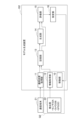
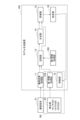
- FIG. 1 is a block diagram showing the configuration of a model generating device according to an embodiment and its peripheral devices.
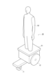
- FIG. 2 is a perspective view showing the configuration of the moving unit.
- FIG. 3 is a flowchart showing a processing procedure for generating a prediction model by the model generation device according to the embodiment.
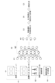
- FIG. 4 is a flow diagram showing a flow of generating a prediction model for predicting communication quality based on physical space information of the moving unit and communication quality of the communication terminal.
- FIG. 5 is a graph showing the estimation results when a test was conducted using a prediction model trained using five hours' worth of robot data and five minutes' worth of human data.
- FIG. 6 is a graph showing estimated values and actual measured values of throughput estimated using 19 hours' worth of robot data and 5 minutes' worth of human data.
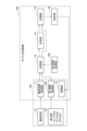
- FIG. 7 is a block diagram showing the configuration of a model generating device according to a first modified example and its peripheral devices.
- FIG. 8 is a block diagram showing the configuration of a model generating device according to the second modified example and its peripheral devices.
- FIG. 9 is a block diagram showing the configuration of a model generating device according to the third modified example and its peripheral devices.
- FIG. 10 is a block diagram showing the configuration of a model generating device according to the fourth modified example and its peripheral devices.
- FIG. 11 is a block diagram showing the hardware configuration of this embodiment.
- Fig. 1 is a block diagram showing the configuration of a model generation device according to an embodiment and its peripheral devices.
- a model generation device 101 includes a moving unit 10, a communication quality acquisition unit 11, an information acquisition unit 12, a storage unit 13, a generation unit 14, an evaluation unit 15, and a designation unit 16.
- the moving unit 10 is capable of moving on the floor surface, and moves on the floor surface along a travel route input by the user or a travel route specified by the specification unit 16 (details of which will be described later).
- the moving unit 10 is equipped with a cart 51 equipped with wheels r1 and r2 and capable of moving on the road, and a robot 52 installed on the upper surface of the cart 51.
- the robot 52 is designed to simulate a human being.
- the relative dielectric constant and electrical conductivity of the robot 52 are designed to be close to those of the human body.
- the moving unit 10 is equipped with a communication terminal 21 and a detection unit 22, which will be described later.
- the robot 52's right hand, left hand, head, and torso can move in a way that mimics the movements of a human. For example, it can hold a communication terminal 21 in its right hand.
- the moving unit 10 may have other configurations as long as it has a configuration capable of reproducing a scenario to be predicted other than the robot 52. Scenarios to be predicted include walking scenes, scenes in which goggles are worn and VR (Virtual Reality) is used, etc.
- the moving unit 10 may be configured without the cart 51 if it can be used in place of a human body. In addition, it does not have to be a combination of the cart 51 and the robot 52, and it may be configured to collect data in place of a human, such as by preparing a bipedal human body model and having it walk on its own.
- the communication terminal 21 shown in FIG. 1 is, for example, a smartphone, a tablet terminal, or a PC (personal computer), and is capable of voice calls, data communications, etc.
- the detection unit 22 detects physical space information of the robot 52.
- the physical space information includes information on the positions, speed, and acceleration of parts of the robot 52 (hands, shoulders, head, etc.).
- the physical space information includes information on obstacles and moving objects that exist around the moving unit 10.
- the detection unit 22 includes at least one of a sensor 22A, a camera 22B, and a GPS receiver 22C.
- the sensor 22A detects the position, speed, acceleration, and combinations of these of parts of the robot 52.
- Sensor 22A is, for example, a three-dimensional position sensor, a speed sensor, and an acceleration sensor. Sensor 22A detects the position, speed, and acceleration of parts of robot 52.
- Camera 22B captures images of robot 52 and analyzes the captured images to detect the positions, speed, and acceleration of parts of robot 52. Camera 22B captures images of the surroundings of robot 52 and analyzes the captured images to detect stationary objects and moving objects present around robot 52.
- the GPS receiver 22C acquires GPS information for the communication terminal 21 by communicating with GPS satellites.
- the communication quality acquisition unit 11 is connected to the communication terminal 21 wirelessly or by wire.
- the communication quality acquisition unit 11 may be integrated with the communication terminal 21.
- the communication quality acquisition unit 11 acquires the communication quality when the communication terminal 21 communicates with an external device via a network.
- the communication quality is, for example, bandwidth throughput, RSSI (Received Signal Strength Indicator) indicating the received signal strength of radio waves, RSRP (Reference Signal Received Power) indicating the radio wave strength of a base station, RSRQ (Reference Signal Received Quality) indicating the received strength of radio waves, and SINR (Signal to Interference and Noise) indicating the reception quality of a signal.
- RSSI Receiveived Signal Strength Indicator
- RSRP Reference Signal Received Power
- RSRQ Reference Signal Received Quality
- SINR Signal to Interference and Noise
- the information acquisition unit 12 acquires physical space information of the moving unit 10 detected by the detection unit 22.
- the information acquisition unit 12 classifies the physical space information into categories, creates a database to be input to a model of a prediction model for predicting wireless communication quality, and utilizes the information as learning data for the prediction model for predicting wireless communication quality.
- the categories include a bounding box 61 shown in C1 of FIG. 4, which will be described later, skeleton coordinate information 62, and GPS information of the communication terminal 21. Note that the components shown within the frame marked with symbol Q1 in FIG. 1 are mounted on the moving unit 10 and move together with the moving unit 10.
- the storage unit 13 includes a storage medium such as a hard disk, and stores the communication quality acquired by the communication quality acquisition unit 11 and the physical space information acquired by the information acquisition unit 12.
- the generation unit 14 performs machine learning based on the communication quality and physical space information stored in the storage unit 13 to generate a prediction model that uses physical space information as input and communication quality as output. That is, the generation unit 14 performs machine learning based on the communication quality and physical space information to associate the physical space information with communication quality.
- the evaluation unit 15 compares the prediction results of the prediction model generated by the generation unit 14 with the communication quality and physical space information stored in the storage unit 13 to evaluate the accuracy of the prediction model. That is, the evaluation unit 15 evaluates the prediction results based on the prediction results of the prediction model and the actual measured values of the communication quality.
- the designation unit 16 designates the movement conditions of the movement unit 10 based on the evaluation result by the evaluation unit 15. Based on the evaluation result by the evaluation unit 15 of the prediction model generated by the generation unit 14, the designation unit 16 outputs an instruction to the movement unit 10 to focus on moving areas where the evaluation of the prediction model is lower than a predetermined value.
- the designation unit 16 designates at least one of an area where the user of the communication terminal 21 can operate and an area where the frequency of operation of the user is higher than a predetermined value as the movement route along which the movement unit 10 moves.
- Fig. 3 is a flowchart showing the processing procedure for generating a prediction model of communication quality
- Fig. 4 is a flow diagram showing the flow for generating a prediction model of communication quality using physical space information of the moving unit 10 and the communication quality of the communication terminal 21 as input.
- the communication quality acquisition unit 11 acquires the communication quality when the communication terminal 21 is communicating with an external device via a network. Furthermore, the information acquisition unit 12 acquires physical space information of the moving unit 10.
- the position, speed, and acceleration of parts of the robot 52 are detected from the coordinates of the image within the bounding box and changes in the coordinates.
- position information of the hands, head, and torso of the robot 52 is detected based on the coordinate information of the skeleton.
- the sensor 22A detects skeletal coordinate information 62, as shown in C1 of FIG. 4 as an example.
- the camera 22B detects information on a bounding box 61 that changes over time, as shown in C1 of FIG. 4 as an example.
- the GPS receiver 22C acquires GPS information 63, as shown in C1 of FIG. 4 as an example. Each of these data is output to the information acquisition unit 12.
- step S12 the storage unit 13 stores the physical space information acquired by the information acquisition unit 12, the communication quality acquired by the communication quality acquisition unit 11, and the GPS information.
- step S13 the generation unit 14 generates a prediction model that takes physical space information as input and outputs communication quality based on the communication quality and physical space information stored in the storage unit 13.
- the generation unit 14 generates a prediction model that estimates communication quality using physical space information as input, using a neural network consisting of an input layer W1, at least one intermediate layer W2, and an output layer W3, as shown in "C2" in Figure 4.
- step S14 the evaluation unit 15 compares the estimation result using the prediction model generated by the generation unit 14 with the communication quality and physical space information stored in the storage unit 13, and evaluates the accuracy of the prediction model based on indicators such as the error between the two. In other words, it determines whether the accuracy of the estimation result using the prediction model generated by the generation unit 14 is higher than a predetermined value.
- step S15 the designation unit 16 designates a driving route along which the moving unit 10 will move. Specifically, the designation unit 16 designates a driving route so as to focus on areas where the evaluation by the evaluation unit 15 is lower than a predetermined value and areas where the surrounding environment has changed significantly. As a result, communication quality and physical space information can be obtained at points where the prediction accuracy is lower than a predetermined value, and the accuracy of the prediction model can be improved. After that, the process is repeated from step S11.
- Figure 5 is a graph showing the estimation results when a test was conducted using a prediction model trained using five hours' worth of data (hereafter referred to as "robot data”) acquired using a robot in accordance with a scenario of straight-line walking, and five minutes' worth of data (hereafter referred to as "human data”) acquired by a person actually carrying a communications terminal 21.
- robot data five hours' worth of data
- human data five minutes' worth of data
- Curve s1 shows the estimation results when 5 hours' worth of robot data and 5 minutes' worth of human data are used
- curve s2 shows the estimation results when only 5 hours' worth of robot data is used
- curve s3 shows the estimation results when only 5 minutes' worth of human data is used.
- curves s1, s2, and s3 where the MAPE is 2% show CDFs of 75%, 68%, and 50%, respectively.
- the CDFs where the MAPE is within 2% are 75%, 68%, and 50%.
- FIG. 6 is a graph showing the results of estimating throughput using 19 hours' worth of robot data and 5 minutes' worth of human data.
- the measured values are shown by solid lines, and the estimated values are shown by dashed lines. It can be seen from the graph shown in FIG. 6 that the results of estimation using the prediction model according to this embodiment are almost identical to the measured values.
- the model generation device 101 includes a moving unit 10, an information acquisition unit 12 that acquires physical space information around the moving unit, a communication quality acquisition unit 11 that acquires communication quality of the moving unit 10 or a communication terminal 21 installed around the moving unit 10, a generation unit 14 that performs machine learning based on the communication quality and the physical space information to generate a prediction model that associates the physical space information with the communication quality, an evaluation unit 15 that evaluates the prediction result based on the prediction result of the prediction model and the actual measured value of the communication quality, and a designation unit 16 that designates the movement conditions of the moving unit 10 based on the evaluation result by the evaluation unit.
- the robot 52 mounted on the moving unit 10 acquires physical space information and generates a predictive model. This reduces the work of a person having to carry a communication terminal to collect physical space information when generating a predictive model, making it possible to simplify the work.
- Human movements are particularly diverse, and it is difficult to obtain the data necessary to predict communication quality based on human movements.
- the robot 52 mounted on the moving unit 10 is moved for a long period of time, and data is obtained focusing on locations where the prediction accuracy is lower than a predetermined value, making it possible to generate a highly accurate prediction model.
- robot data can be used as a precise substitute for human data, making it possible to collect the vast amounts of data required for deep learning.
- Fig. 7 is a block diagram showing the configuration of a model generation device 102 according to a first modified example.
- the first modified example differs from the first embodiment described above in that the communication terminal 21 and the communication quality acquisition unit 11 are not mounted on the moving unit 10. That is, the components in the symbol Q2 are mounted on the moving unit 10 and move together with the moving unit 10.
- the communication terminal 21 and the communication quality acquisition unit 11 are mounted on a control device installed in, for example, a base station that remotely operates the mobile unit 10.
- a control device installed in, for example, a base station that remotely operates the mobile unit 10.
- the model generation device 102 it becomes possible to generate a prediction model capable of predicting the communication quality of the communication terminal 21, for example, when the mobile unit 10 passes near a person who is communicating using the communication terminal 21.
- FIG. 8 is a block diagram showing the configuration of a model generating device 103 according to the second modified example.
- the second modified example is equipped with a first information acquisition unit 12A and a second information acquisition unit 12B, and differs from the first embodiment described above in that the first information acquisition unit 12A is mounted on the moving unit 10, while the second information acquisition unit 12B is not mounted on the moving unit 10.
- the components in the symbol Q3 are mounted on the moving unit 10 and move together with the moving unit 10.
- the second information acquisition unit acquires various types of physical space information, for example, from a detection unit (not shown) such as a sensor or camera installed near the road on which the moving unit 10 travels.
- a detection unit such as a sensor or camera installed near the road on which the moving unit 10 travels.
- the first information acquisition unit 12A and the second information acquisition unit 12B it is possible to acquire physical space information in the vicinity of the moving unit 10 and physical space information around the moving unit 10, making it possible to generate a prediction model with higher accuracy.
- FIG. 9 is a block diagram showing the configuration of a model generation device 104 according to the third modified example.
- the third modified example is equipped with a first information acquisition unit 12A and a second information acquisition unit 12B, and differs from the first modified example shown in FIG. 7 in that the first information acquisition unit 12A is mounted on the moving unit 10, while the second information acquisition unit 12B is not mounted on the moving unit 10.
- the components in the symbol Q4 are mounted on the moving unit 10 and move together with the moving unit 10.
- the second information acquisition unit 12B acquires various types of physical space information, for example, from a detection unit (not shown) such as a sensor or a camera that is installed near the road on which the moving unit 10 travels.
- a detection unit such as a sensor or a camera that is installed near the road on which the moving unit 10 travels.
- the model generation device 104 is capable of generating a prediction model that can predict the communication quality of the communication terminal 21 when the moving unit 10 passes near a person who is communicating using the communication terminal 21.
- FIG. 10 is a block diagram showing the configuration of a model generating device 105 according to the fourth modified example.
- the fourth modified example differs from the first embodiment described above in that the communication quality acquisition unit 11 and the information acquisition unit 12 are not mounted on the moving unit 10.
- the components in the symbol Q5 are mounted on the moving unit 10 and move together with the moving unit 10.
- the communication quality acquisition unit 11 is mounted on, for example, a control device installed in a base station that remotely operates the mobile unit 10.
- the detection unit 22 and the information acquisition unit 12 are installed, for example, near the road on which the mobile unit 10 travels, and acquire various types of physical space information.
- model generation device 105 In the model generation device 105 according to the fourth modified example, only the moving unit 10 moves, and the other components do not move together with the moving unit 10. Therefore, as in the first and third modified examples, it becomes possible to generate a prediction model capable of predicting the communication quality of the communication terminal 21, for example, when the moving unit 10 passes near a person who is communicating using the communication terminal 21.
- the model generating device 101 of the present embodiment described above can be, for example, a general-purpose computer system including a CPU (Central Processing Unit, processor) 901, memory 902, storage 903 (HDD: Hard Disk Drive, SSD: Solid State Drive), communication device 904, input device 905, and output device 906, as shown in FIG. 11.
- the memory 902 and storage 903 are storage devices.
- the CPU 901 executes a predetermined program loaded onto the memory 902, thereby realizing each function of the model generating device 101.
- the model generating device 101 may be implemented in one computer, or in multiple computers.
- the model generating device 101 may also be a virtual machine implemented in a computer.
- the program for the model generating device 101 can be stored on a computer-readable recording medium such as a HDD, SSD, USB (Universal Serial Bus) memory, CD (Compact Disc), or DVD (Digital Versatile Disc), or can be distributed via a network.
- a computer-readable recording medium such as a HDD, SSD, USB (Universal Serial Bus) memory, CD (Compact Disc), or DVD (Digital Versatile Disc), or can be distributed via a network.
- the computer-readable recording medium is, for example, a non-transitory recording medium.
Landscapes
- Engineering & Computer Science (AREA)
- Computer Networks & Wireless Communication (AREA)
- Signal Processing (AREA)
- Management, Administration, Business Operations System, And Electronic Commerce (AREA)
Abstract
移動部(10)と、移動部周辺のフィジカル空間情報を取得する取得部(12)と、移動部(10)、または移動部(10)の周辺に設置された通信端末(21)の通信品質を取得する通信部(11)と、通信品質と、フィジカル空間情報に基づいて機械学習を実施し、フィジカル空間情報と通信品質を対応づける予測モデルを生成する生成部(14)と、予測モデルの予測結果と、通信品質の実測値に基づいて、予測結果を評価する評価部(15)と、評価部(15)による評価結果に基づいて、移動部(10)の移動条件を指定する指定部(16)を備える。
Description
本開示は、モデル生成装置及びモデル生成方法並びにモデル生成プログラムに関する。
通信デバイスを用いて無線通信を行う場合には、その周辺に存在する物体の移動などの環境の変化に応じて通信品質が変化する。環境の変化により、通信デバイスによるサービス、或いは、システムが要求する通信品質を満たせなくなる可能性がある。
例えば、「IEEE802.11ad」、セルラー通信などの第5世代通信(5G通信)では、波長がミリメートル帯の高い周波数を用いるため、無線通信を行う送受の間の遮蔽物によるブロッキングが通信品質に大きな影響を与える。
予め通信品質を予測できれば、サービス或いはシステムが影響を受ける前に対策がとれる可能性がある。非特許文献1、2には、深度カメラから取得するフィジカル空間情報を用いて、オブジェクトの通過によるミリ波通信の無線通信路遮断時における通信品質を予測することが開示されている。
T. Nishio,H. Okamoto, K. Nakashima, Y. Koda, K. Yamamoto, M. Morikura, Y. Asai, and R. Miyatake, "Proactive Received Power Prediction Using Machine Learningand Depth Imagesfor mmWave Networks," IEEE Journal on Selected Areasin Communications, vol. 37, no. 11, pp. 2413-2427, Nov. 2019. doi: 10.1109/JSAC.2019.2933763.
H. Okamotoet al., "Machine-learning-based throughput estimation using imagesfor mmWave communications," in Proc.,IEEE VTC 2017-spring, Jan. 2017.
しかし、上述した非特許文献1、2では、無線通信品質のモデルを生成する際に、人が実験に参加して無線通信品質の予測に必要なデータを収集する。例えば、人が通信端末を所持して歩く、人がVRデバイスを装着して歩く、などの動作を行ってデータを収集するので、人手による多くの労力を要するという問題がある。
また、人は多様な動きをするため、それらのバリエーションを考慮したデータの収集は難しいという問題がある。このため、データ不足に陥ってしまい、予測精度が部分的に低下する可能性があった。
本開示は、上記事情に鑑みてなされたものであり、その目的とするところは、人手の労力を軽減してデータを収集し、予測モデルを生成することが可能なモデル生成装置及びモデル生成方法並びにモデル生成プログラムを提供することにある。
本開示の一態様のモデル生成装置は、移動部と、前記移動部周辺のフィジカル空間情報を取得する情報取得部と、前記移動部、または前記移動部の周辺に設置された通信端末の通信品質を取得する通信品質取得部と、前記通信品質と、前記フィジカル空間情報に基づいて機械学習を実施し、前記フィジカル空間情報と通信品質を対応づける予測モデルを生成する生成部と、前記予測モデルの予測結果と、前記通信品質の実測値に基づいて、前記予測結果を評価する評価部と、前記評価部による評価結果に基づいて、前記移動部の移動条件を指定する指定部と、を備える。
本開示の一態様のモデル生成方法は、移動部周辺のフィジカル空間情報を取得し、前記移動部、または前記移動部の周辺に設置された通信端末の通信品質を取得し、前記通信品質と、前記フィジカル空間情報に基づいて機械学習を実施し、前記フィジカル空間情報と通信品質を対応づける予測モデルを生成し、前記予測モデルの予測結果と、前記通信品質の実測値に基づいて、前記予測結果を評価し、評価結果に基づいて、前記移動部の移動条件を指定する。
本開示の一態様は、上記モデル生成装置としてコンピュータを機能させるためのモデル生成プログラムである。
本開示によれば、人手の労力を軽減してデータを収集し、予測モデルを生成することが可能になる。
[実施形態の説明]
以下、図面を参照して実施形態について説明する。図1は、実施形態に係るモデル生成装置、及びその周辺機器の構成を示すブロック図である。図1に示すように、実施形態に係るモデル生成装置101は、移動部10と、通信品質取得部11と、情報取得部12と、記憶部13と、生成部14と、評価部15と、指定部16を備えている。
以下、図面を参照して実施形態について説明する。図1は、実施形態に係るモデル生成装置、及びその周辺機器の構成を示すブロック図である。図1に示すように、実施形態に係るモデル生成装置101は、移動部10と、通信品質取得部11と、情報取得部12と、記憶部13と、生成部14と、評価部15と、指定部16を備えている。
移動部10は、床面を移動可能であり、ユーザにより入力された走行経路或いは指定部16(詳細は後述する)にて指定された走向経路に沿って床面上を移動する。移動部10は、例えば図2に示すように、車輪r1、r2が搭載されて路上を走向可能な台車51と、台車51の上面に設置されたロボット52を備えている。ロボット52は、人間を模擬して設計されている。ロボット52の比誘電率、導電率は人体に近づくように設計されている。移動部10には、後述する通信端末21及び検出部22が設けられている。
ロボット52は、右手、左手、頭部、胴体が人間の動作を模擬して動作可能である。例えば、右手で通信端末21を所持することができる。
移動部10は、ロボット52以外にも予測対象のシナリオを再現できる構成を有していれば、他の構成としても良い。予測対象のシナリオとは、歩行シーン、ゴーグルを装着してVR(Virtual Reality)を利用するシーンなどである。移動部10は、人体の代用が可能であれば、台車51を設けない構成としてもよい。また、台車51とロボット52の組み合わせでなくてもよく、二足歩行が可能な人体模型を用意してそれ自身で歩行させるなど、人の代わりにデータ収集できる構成であれば良い。
図1に示す通信端末21は、例えばスマートフォン、タブレット端末、PC(personal computer)であり、音声通話、データ通信などが可能である。
検出部22は、ロボット52のフィジカル空間情報を検出する。フィジカル空間情報は、ロボット52の部位(手、肩、頭部など)の位置、速度、及び加速度の情報を含む。フィジカル空間情報は、移動部10の周囲に存在する障害物、移動物体の情報を含む。
検出部22は、センサ22A、カメラ22B、及びGPS受信機22Cのうちの少なくとも一つを含む。センサ22Aは、ロボット52の部位の位置、速度、加速度、及びこれらの組み合わせを検出する。
センサ22Aは、例えば三次元位置センサ、速度センサ、及び加速度センサである。センサ22Aは、ロボット52の部位の位置、速度、及び加速度を検出する。
カメラ22Bは、ロボット52を撮像し、撮像した画像を解析してロボット52の部位の位置、速度、及び加速度を検出する。カメラ22Bは、ロボット52の周囲画像を撮像し、撮像した画像を解析してロボット52の周囲に存在する静止物体、及び移動物体を検出する。
GPS受信機22Cは、GPS衛星との通信により、通信端末21のGPS情報を取得する。
通信品質取得部11は、無線或いは有線にて通信端末21と接続されている。通信品質取得部11は、通信端末21と一体化されていてもよい。通信品質取得部11は、通信端末21がネットワークを経由して外部機器と通信しているときの通信品質を取得する。通信品質は、例えば帯域のスループット、電波の受信信号強度を表すRSSI(Received Signal StrengthIndicator)、基地局の電波強度を表すRSRP(Reference SignalReceived Power)、電波の受信強度を表すRSRQ(Reference Signal ReceivedQuality)、信号の受信品質を表すSINR(Signal to Interference and Noise)である。これらの数値が大きいほど通信品質が高い。また、通信品質は、データのダウンロードに要する時間を含む。この時間が短いほど通信品質は高い。
情報取得部12は、検出部22で検出された移動部10のフィジカル空間情報を取得する。情報取得部12は、フィジカル空間情報をカテゴリごとに分類し、無線通信品質予測の予測モデルのモデルへ入力するデータベースを作成し、無線通信品質予測の予測モデルの学習データとして活用する。カテゴリとは、後述する図4のC1に示すバウンディングボックス61、骨格座標情報62、通信端末21のGPS情報などである。なお、図1に示す符号Q1の枠内に示す構成要素は、移動部10に搭載され、移動部10と共に移動する。
記憶部13は、例えばハードディスクなどの記憶媒体を備えており、通信品質取得部11で取得した通信品質、及び情報取得部12で取得したフィジカル空間情報を記憶する。
生成部14は、記憶部13に記憶されている通信品質、及びフィジカル空間情報に基づいて機械学習を実施することにより、フィジカル空間情報を入力とし、通信品質を出力とする予測モデルを生成する。即ち、生成部14は、通信品質と、フィジカル空間情報に基づいて機械学習を実施し、フィジカル空間情報と通信品質を対応づける。
評価部15は、生成部14で生成された予測モデルによる予測結果と、記憶部13に記憶されている通信品質、及びフィジカル空間情報を比較して、予測モデルの精度を評価する。即ち、評価部15は、予測モデルの予測結果と、通信品質の実測値に基づいて、予測結果を評価する。
指定部16は、評価部15による評価結果に基づいて、移動部10の移動条件を指定する。指定部16は、生成部14で生成された予測モデルに対して評価部15が評価した結果に基づき、予測モデルの評価が所定値よりも低い領域を重点的に移動させる指示を、移動部10に出力する。指定部16は、通信端末21のユーザが動作可能な領域、及びユーザが動作する頻度が所定値よりも高い領域の少なくとも一方を、移動部10が移動する移動経路に指定する。
次に、上述した本実施形態に係るモデル生成装置101の動作について、図3、図4を参照して説明する。図3は、通信品質の予測モデルを生成する処理手順を示すフローチャート、図4は、移動部10のフィジカル空間情報、及び通信端末21の通信品質を入力として、通信品質の予測モデルを生成する流れを示すフロー図である。
初めに図3に示すステップS11において通信品質取得部11は、通信端末21がネットワークを経由して外部機器と通信しているときの通信品質を取得する。更に情報取得部12は、移動部10のフィジカル空間情報を取得する。
例えば、図4のC1に示すように、バウンディングボックス内の画像の座標、及び座標の変化から、ロボット52の部位の位置、速度、加速度を検出する。また、骨格の座標情報に基づいて、ロボット52の手、頭部、胴体の位置情報を検出する。
センサ22Aは、一例として図4のC1に示す骨格座標情報62を検出する。カメラ22Bは、一例として図4のC1に示す時系列的に変化するバウンディングボックス61の情報を検出する。GPS受信機22Cは、例えば図4のC1に示すGPS情報63を取得する。これらの各データは情報取得部12に出力される。
ステップS12において記憶部13は、情報取得部12で取得されたフィジカル空間情報、及び通信品質取得部11で取得された通信品質、及びGPS情報を記憶する。
ステップS13において生成部14は、記憶部13に記憶されている通信品質、及びフィジカル空間情報に基づいて、フィジカル空間情報を入力とし、通信品質を出力とする予測モデルを生成する。生成部14は、図4の「C2」に示すように入力層W1、少なくとも一つの中間層W2、及び出力層W3からなるニューラルネットワークにより、フィジカル空間情報を入力として通信品質を推定する予測モデルを生成する。
ステップS14において評価部15は、生成部14で生成された予測モデルを用いた推定結果と、記憶部13に記憶されている通信品質及びフィジカル空間情報を比較して、双方の誤差などの指標に基づき、予測モデルの精度を評価する。即ち、生成部14で生成された予測モデルによる推定結果の精度が所定値よりも高いか否かを判定する。
ステップS15において指定部16は、移動部10が移動する走行路を指定する。具体的には、評価部15による評価が所定値よりも低い領域、周辺環境が大きく変化した領域を重点的に走向するように、走行路を指定する。その結果、予測精度が所定値よりも低い地点において、通信品質及びフィジカル空間情報を取得することができ、予測モデルの精度を向上させることができる。その後、ステップS11からの処理を繰り返す。
図5は、直線歩行のシナリオに沿って、ロボットを用いて取得した5時間分のデータ(以下、「ロボットデータ」という)と、人が実際に通信端末21を所持して取得した5分間分のデータ(以下、「人データ」という)を用意し、これらを用いて学習させた予測モデルを用いて、テストを実施したときの推定結果を示すグラフである。図5に示す横軸は、平均絶対パーセント誤差(MAPE:Mean Absolute Percentage Error)を示し、縦軸は累積分布関数(CDF)を示している。
曲線s1は、5時間分のロボットデータ及び5分間分の人データを用いたときの推定結果を示し、曲線s2は、5時間分のロボットデータのみを用いたときの推定結果を示し、曲線s3は、5分間分の人データのみを用いたときの推定結果を示している。
図5に示すMAPEが2%における曲線s1、s2、s3では、CDFはそれぞれ75%、68%、50%を示している。即ち、各曲線s1、s2、s3において、MAPEが2%以内となるCDFが75%、68%、50%であることを示している。このため、図5に示すグラフで、左上にあるほど精度が高いことになり、曲線s1、s2の5時間分のロボットデータを用いて予測モデルを作成することにより、より高精度な予測モデルが生成できることが理解される。
図6は、19時間分のロボットデータ、及び5分間分の人データを用いて、スループットを推定した結果を示すグラフである。図6において、測定値を実線で示し、推定値を破線で示している。図6に示すグラフから本実施形態に係る予測モデルを使用して推定した結果、ほぼ測定値と一致していることが理解される。
このように、本実施形態に係るモデル生成装置101は、移動部10と、移動部周辺のフィジカル空間情報を取得する情報取得部12と、移動部10または移動部10の周辺に設置された通信端末21の通信品質を取得する通信品質取得部11と、通信品質と、フィジカル空間情報に基づいて機械学習を実施し、フィジカル空間情報と通信品質を対応づける予測モデルを生成する生成部14と、予測モデルの予測結果と、通信品質の実測値に基づいて、予測結果を評価する評価部15と、評価部による評価結果に基づいて、移動部10の移動条件を指定する指定部16と、を備える。
本実施形態では、移動部10に搭載したロボット52により、フィジカル空間情報を取得して、予測モデルを生成する。このため、予測モデルの生成時に、人が通信端末を所持してフィジカル空間情報を収集するという作業が軽減され、作業を簡素化することが可能になる。
特に人の動きは多様であり、人の動きに基づいて通信品質の予測に必要なデータを取得することは難しい。本実施形態では、移動部10に搭載したロボット52を長時間移動させ、且つ、予測精度が所定値よりも低い箇所において重点的にデータを取得することにより、高精度な予測モデルを生成することが可能になる。
また、ロボットデータを用いることで人データを精緻に代用することができ、深層学習に必要な膨大なデータ量を収集することが可能になる。
[変形例の説明]
次に、上述した実施形態に係るモデル生成装置101の変形例について説明する。図7は、第1変形例に係るモデル生成装置102の構成を示すブロック図である。図7に示すように、第1変形例では、通信端末21、及び通信品質取得部11が移動部10に搭載されていない点で前述した第1実施形態と相違する。即ち、符号Q2内の構成要素が移動部10に搭載され、移動部10と共に移動する。
次に、上述した実施形態に係るモデル生成装置101の変形例について説明する。図7は、第1変形例に係るモデル生成装置102の構成を示すブロック図である。図7に示すように、第1変形例では、通信端末21、及び通信品質取得部11が移動部10に搭載されていない点で前述した第1実施形態と相違する。即ち、符号Q2内の構成要素が移動部10に搭載され、移動部10と共に移動する。
通信端末21及び通信品質取得部11は、例えば移動部10を遠隔で操作する基地局に設置した制御装置に搭載される。第1変形例に係るモデル生成装置102では、例えば通信端末21を用いて通信している人の近傍を移動部10が通過した場合において、通信端末21の通信品質を予測可能な予測モデルを生成することが可能になる。
図8は、第2変形例に係るモデル生成装置103の構成を示すブロック図である。図8に示すように、第2変形例では、第1情報取得部12A及び第2情報取得部12Bを備えており、第1情報取得部12Aが移動部10に搭載され、第2情報取得部12Bが移動部10に搭載されていない点で前述した第1実施形態と相違する。即ち、符号Q3内の構成要素が移動部10に搭載され、移動部10と共に移動する。
第2情報取得部は、例えば移動部10が走行する走行路の近傍に設置されているセンサ、カメラなどの検出部(図示省略)から、各種のフィジカル空間情報を取得する。
第1情報取得部12A、及び第2情報取得部12Bを備えることにより、移動部10近傍のフィジカル空間情報、及び移動部10の周辺のフィジカル空間情報を取得することができ、より高精度に予測モデルを生成することが可能になる。
図9は、第3変形例に係るモデル生成装置104の構成を示すブロック図である。図9に示すように、第3変形例では、第1情報取得部12A及び第2情報取得部12Bを備えており、第1情報取得部12Aが移動部10に搭載され、第2情報取得部12Bが移動部10に搭載されていない点で図7に示した第1変形例と相違する。即ち、符号Q4内の構成要素が移動部10に搭載され、移動部10と共に移動する。
第2情報取得部12Bは、例えば移動部10が走行する走行路の近傍に設置されているセンサ、カメラなどの検出部(図示省略)から、各種のフィジカル空間情報を取得する。第3変形例に係るモデル生成装置104では、第1変形例と同様に、例えば通信端末21を用いて通信している人の近傍を移動部10が通過した場合において、通信端末21の通信品質を予測可能な予測モデルを生成することが可能になる。
また、第1変形例と同様に、移動部10近傍のフィジカル空間情報、及び移動部10の周辺のフィジカル空間情報を取得することができ、より高精度に予測モデルを生成することが可能になる。
図10は、第4変形例に係るモデル生成装置105の構成を示すブロック図である。図10に示すように、第4変形例では、通信品質取得部11及び情報取得部12が移動部10に搭載されていない点で前述した第1実施形態と相違する。即ち、符号Q5内の構成要素が移動部10に搭載され、移動部10と共に移動する。
通信品質取得部11は、例えば移動部10を遠隔で操作する基地局に設置した制御装置に搭載される。検出部22及び情報取得部12は、例えば移動部10が走行する走行路の近傍に設置されて、各種のフィジカル空間情報を取得する。
第4変形例に係るモデル生成装置105では、移動部10のみが移動し、それ以外の構成要素は、移動部10と共に移動しない。このため、第1、第3変形例と同様に、例えば通信端末21を用いて通信している人の近傍を移動部10が通過した場合において、通信端末21の通信品質を予測可能な予測モデルを生成することが可能になる。
また、通信端末21、及び検出部22が移動部10に搭載されないので、構成を簡素化することが可能になる。
上記説明した本実施形態のモデル生成装置101には、図11に示すように例えば、CPU(Central Processing Unit、プロセッサ)901と、メモリ902と、ストレージ903(HDD:Hard Disk Drive、SSD:Solid StateDrive)と、通信装置904と、入力装置905と、出力装置906とを備える汎用的なコンピュータシステムを用いることができる。メモリ902およびストレージ903は、記憶装置である。このコンピュータシステムにおいて、CPU901がメモリ902上にロードされた所定のプログラムを実行することにより、モデル生成装置101の各機能が実現される。
なお、モデル生成装置101は、1つのコンピュータで実装されてもよく、あるいは複数のコンピュータで実装されても良い。また、モデル生成装置101は、コンピュータに実装される仮想マシンであっても良い。
なお、モデル生成装置101用のプログラムは、HDD、SSD、USB(Universal Serial Bus)メモリ、CD (Compact Disc)、DVD (Digital Versatile Disc)などのコンピュータ読取り可能な記録媒体に記憶することも、ネットワークを介して配信することもできる。コンピュータ読取り可能な記録媒体は、例えば非一時的な(non-transitory)記録媒体である。
なお、本開示は上記実施形態に限定されるものではなく、その要旨の範囲内で数々の変形が可能である。
10 移動部
11 通信品質取得部
12 情報取得部
12A 第1情報取得部
12B 第2情報取得部
13 記憶部
14 生成部
15 評価部
16 指定部
21 通信端末
22 検出部
22A センサ
22B カメラ
22C GPS受信機
51 台車
52 ロボット
61 バウンディングボックス
62 骨格座標情報
63 GPS情報
101、102、103、104、105 モデル生成装置
11 通信品質取得部
12 情報取得部
12A 第1情報取得部
12B 第2情報取得部
13 記憶部
14 生成部
15 評価部
16 指定部
21 通信端末
22 検出部
22A センサ
22B カメラ
22C GPS受信機
51 台車
52 ロボット
61 バウンディングボックス
62 骨格座標情報
63 GPS情報
101、102、103、104、105 モデル生成装置
Claims (7)
- 移動部と、
前記移動部周辺のフィジカル空間情報を取得する情報取得部と、
前記移動部、または前記移動部の周辺に設置された通信端末の通信品質を取得する通信品質取得部と、
前記通信品質と、前記フィジカル空間情報に基づいて機械学習を実施し、前記フィジカル空間情報と通信品質を対応づける予測モデルを生成する生成部と、
前記予測モデルの予測結果と、前記通信品質の実測値に基づいて、前記予測結果を評価する評価部と、
前記評価部による評価結果に基づいて、前記移動部の移動条件を指定する指定部と、
を備えたモデル生成装置。 - 前記情報取得部は、前記移動部に搭載され、該移動部周辺の画像を撮像するカメラ、及び、移動部の部位の位置、速度、加速度の少なくとも1つを検出するセンサから、前記フィジカル空間情報を取得する
請求項1に記載のモデル生成装置。 - 前記指定部は、通信端末のユーザが動作可能な領域、及びユーザが動作する頻度が所定値よりも高い領域の少なくとも一方を、前記移動部の移動経路に指定する
請求項1に記載のモデル生成装置。 - 前記指定部は、予測モデルの評価が所定値よりも低い領域を、前記移動部の移動経路に指定する
請求項1に記載のモデル生成装置。 - 前記情報取得部は、前記移動部に搭載された第1情報取得部、及び前記移動部に搭載されない第2情報取得部、
を含む請求項1に記載のモデル生成装置。 - 移動部周辺のフィジカル空間情報を取得し、
前記移動部、または前記移動部の周辺に設置された通信端末の通信品質を取得し、
前記通信品質と、前記フィジカル空間情報に基づいて機械学習を実施し、前記フィジカル空間情報と通信品質を対応づける予測モデルを生成し、
前記予測モデルの予測結果と、前記通信品質の実測値に基づいて、前記予測結果を評価し、
評価結果に基づいて、前記移動部の移動条件を指定する
モデル生成方法。 - 請求項1に記載のモデル生成装置としてコンピュータを機能させるモデル生成プログラム。
Priority Applications (2)
| Application Number | Priority Date | Filing Date | Title |
|---|---|---|---|
| PCT/JP2022/042108 WO2024100893A1 (ja) | 2022-11-11 | 2022-11-11 | モデル生成装置及びモデル生成方法並びにモデル生成プログラム |
| JP2024556995A JPWO2024100893A1 (ja) | 2022-11-11 | 2022-11-11 |
Applications Claiming Priority (1)
| Application Number | Priority Date | Filing Date | Title |
|---|---|---|---|
| PCT/JP2022/042108 WO2024100893A1 (ja) | 2022-11-11 | 2022-11-11 | モデル生成装置及びモデル生成方法並びにモデル生成プログラム |
Publications (1)
| Publication Number | Publication Date |
|---|---|
| WO2024100893A1 true WO2024100893A1 (ja) | 2024-05-16 |
Family
ID=91032148
Family Applications (1)
| Application Number | Title | Priority Date | Filing Date |
|---|---|---|---|
| PCT/JP2022/042108 Ceased WO2024100893A1 (ja) | 2022-11-11 | 2022-11-11 | モデル生成装置及びモデル生成方法並びにモデル生成プログラム |
Country Status (2)
| Country | Link |
|---|---|
| JP (1) | JPWO2024100893A1 (ja) |
| WO (1) | WO2024100893A1 (ja) |
Citations (1)
| Publication number | Priority date | Publication date | Assignee | Title |
|---|---|---|---|---|
| CN113839725A (zh) * | 2020-06-24 | 2021-12-24 | 华为技术有限公司 | 无线信号传播预测方法及装置 |
-
2022
- 2022-11-11 WO PCT/JP2022/042108 patent/WO2024100893A1/ja not_active Ceased
- 2022-11-11 JP JP2024556995A patent/JPWO2024100893A1/ja active Pending
Patent Citations (1)
| Publication number | Priority date | Publication date | Assignee | Title |
|---|---|---|---|---|
| CN113839725A (zh) * | 2020-06-24 | 2021-12-24 | 华为技术有限公司 | 无线信号传播预测方法及装置 |
Non-Patent Citations (1)
| Title |
|---|
| RIICH KUDO: "Wireless Link Quality Prediction Using Physical Space Information based on Deep Learning", IEICE TRANSACTIONS ON INFORMATION AND COMMUNICATION ENGINEERS, B, vol. J105-B, no. 10, 12 May 2022 (2022-05-12), pages 749 - 760, XP093169416, DOI: 10.14923/transcomj.2021mji0003 * |
Also Published As
| Publication number | Publication date |
|---|---|
| JPWO2024100893A1 (ja) | 2024-05-16 |
Similar Documents
| Publication | Publication Date | Title |
|---|---|---|
| US12028788B2 (en) | Communication system and base station | |
| Atia et al. | Dynamic online-calibrated radio maps for indoor positioning in wireless local area networks | |
| KR102332925B1 (ko) | 무선 커버리지를 제공하기 위한 방법 및 디바이스들 | |
| Butt et al. | ML-assisted UE positioning: Performance analysis and 5G architecture enhancements | |
| CN105336097B (zh) | 人口流动轨迹的交通预警方法及装置 | |
| JP6296454B2 (ja) | 基地局による測位方法及び装置 | |
| Mohamed et al. | DeepFeat: Robust large-scale multi-features outdoor localization in LTE networks using deep learning | |
| KR102398413B1 (ko) | 건설 통합 플랫폼을 제공하는 방법 및 장치 | |
| Shin et al. | MRI: Model-based radio interpolation for indoor war-walking | |
| US20220345919A1 (en) | Communication terminal and communication quality prediction method | |
| Nguyen et al. | Low speed vehicle localization using wifi fingerprinting | |
| Kianoush et al. | Leveraging RF signals for human sensing: fall detection and localization in human-machine shared workspaces | |
| Dashti et al. | RSSI localization with Gaussian processes and tracking | |
| EP4205311A1 (en) | Technique for predicting radio quality | |
| CN109462820B (zh) | 一种用于跟踪低速移动车辆的rssi拟合方法 | |
| Wang et al. | Mobile device localization in 5G wireless networks | |
| Zheng et al. | RSS-based indoor passive localization using clustering and filtering in a LTE network | |
| KR20200074719A (ko) | 이동체의 자기 위치 추정 방법 및 그 이동체 | |
| US20250315238A1 (en) | Charging station update platform | |
| CN114514437B (zh) | 用于定位和跟踪的传感器选择的方法和装置 | |
| JP2018115974A (ja) | 情報処理装置、情報処理方法、およびプログラム | |
| Palaniappan et al. | Autonomous RF surveying robot for indoor localization and tracking | |
| TW201728361A (zh) | 以無線訊號強度評估卡路里消耗量之分析系統及分析方法 | |
| JP7453587B2 (ja) | 通信品質予測装置、通信品質予測システム、通信品質予測方法、及び、通信品質予測プログラム | |
| KR102492309B1 (ko) | 사용자 단말 및 이를 이용한 위치 추정 방법 |
Legal Events
| Date | Code | Title | Description |
|---|---|---|---|
| 121 | Ep: the epo has been informed by wipo that ep was designated in this application |
Ref document number: 22965217 Country of ref document: EP Kind code of ref document: A1 |
|
| WWE | Wipo information: entry into national phase |
Ref document number: 2024556995 Country of ref document: JP |
|
| NENP | Non-entry into the national phase |
Ref country code: DE |
|
| 122 | Ep: pct application non-entry in european phase |
Ref document number: 22965217 Country of ref document: EP Kind code of ref document: A1 |