WO2024100723A1 - ガスセンサ - Google Patents
ガスセンサ Download PDFInfo
- Publication number
- WO2024100723A1 WO2024100723A1 PCT/JP2022/041407 JP2022041407W WO2024100723A1 WO 2024100723 A1 WO2024100723 A1 WO 2024100723A1 JP 2022041407 W JP2022041407 W JP 2022041407W WO 2024100723 A1 WO2024100723 A1 WO 2024100723A1
- Authority
- WO
- WIPO (PCT)
- Prior art keywords
- gas
- resonators
- light
- gas sensor
- sensor according
- Prior art date
- Legal status (The legal status is an assumption and is not a legal conclusion. Google has not performed a legal analysis and makes no representation as to the accuracy of the status listed.)
- Ceased
Links
Images


Classifications
-
- G—PHYSICS
- G01—MEASURING; TESTING
- G01N—INVESTIGATING OR ANALYSING MATERIALS BY DETERMINING THEIR CHEMICAL OR PHYSICAL PROPERTIES
- G01N21/00—Investigating or analysing materials by the use of optical means, i.e. using sub-millimetre waves, infrared, visible or ultraviolet light
- G01N21/17—Systems in which incident light is modified in accordance with the properties of the material investigated
- G01N21/25—Colour; Spectral properties, i.e. comparison of effect of material on the light at two or more different wavelengths or wavelength bands
- G01N21/31—Investigating relative effect of material at wavelengths characteristic of specific elements or molecules, e.g. atomic absorption spectrometry
- G01N21/35—Investigating relative effect of material at wavelengths characteristic of specific elements or molecules, e.g. atomic absorption spectrometry using infrared light
- G01N21/3504—Investigating relative effect of material at wavelengths characteristic of specific elements or molecules, e.g. atomic absorption spectrometry using infrared light for analysing gases, e.g. multi-gas analysis
-
- G—PHYSICS
- G01—MEASURING; TESTING
- G01N—INVESTIGATING OR ANALYSING MATERIALS BY DETERMINING THEIR CHEMICAL OR PHYSICAL PROPERTIES
- G01N21/00—Investigating or analysing materials by the use of optical means, i.e. using sub-millimetre waves, infrared, visible or ultraviolet light
- G01N21/01—Arrangements or apparatus for facilitating the optical investigation
- G01N21/03—Cuvette constructions
- G01N21/031—Multipass arrangements
-
- G—PHYSICS
- G01—MEASURING; TESTING
- G01N—INVESTIGATING OR ANALYSING MATERIALS BY DETERMINING THEIR CHEMICAL OR PHYSICAL PROPERTIES
- G01N21/00—Investigating or analysing materials by the use of optical means, i.e. using sub-millimetre waves, infrared, visible or ultraviolet light
- G01N21/17—Systems in which incident light is modified in accordance with the properties of the material investigated
- G01N21/25—Colour; Spectral properties, i.e. comparison of effect of material on the light at two or more different wavelengths or wavelength bands
- G01N21/31—Investigating relative effect of material at wavelengths characteristic of specific elements or molecules, e.g. atomic absorption spectrometry
- G01N21/39—Investigating relative effect of material at wavelengths characteristic of specific elements or molecules, e.g. atomic absorption spectrometry using tunable lasers
-
- G—PHYSICS
- G01—MEASURING; TESTING
- G01N—INVESTIGATING OR ANALYSING MATERIALS BY DETERMINING THEIR CHEMICAL OR PHYSICAL PROPERTIES
- G01N21/00—Investigating or analysing materials by the use of optical means, i.e. using sub-millimetre waves, infrared, visible or ultraviolet light
- G01N21/17—Systems in which incident light is modified in accordance with the properties of the material investigated
- G01N21/25—Colour; Spectral properties, i.e. comparison of effect of material on the light at two or more different wavelengths or wavelength bands
- G01N21/31—Investigating relative effect of material at wavelengths characteristic of specific elements or molecules, e.g. atomic absorption spectrometry
- G01N21/39—Investigating relative effect of material at wavelengths characteristic of specific elements or molecules, e.g. atomic absorption spectrometry using tunable lasers
- G01N2021/391—Intracavity sample
Definitions
- This disclosure relates to a gas sensor.
- Gas molecules have a light absorption spectrum with a specific wavelength. Therefore, the gas type is determined by causing a laser beam with a narrow spectral linewidth to interfere with the gas and detecting the absorption of the laser beam by the gas (see, for example, Patent Document 1).
- This disclosure has been made to solve the problems described above, and its purpose is to obtain a small, inexpensive gas sensor.
- the gas sensor according to the present disclosure comprises one gain medium, a plurality of resonators having different resonator lengths and simultaneously generating a plurality of laser beams having different wavelengths from the light emitted from the gain medium, and a light receiving element for detecting the plurality of laser beams, and is characterized in that the plurality of laser beams are made to interfere with the gas to be measured inside the plurality of resonators.
- multiple resonators with different resonator lengths it is possible to obtain laser light of multiple wavelengths even with a single gain medium.
- Multiple laser light beams are made to interfere with the measured gas inside the multiple resonators, and multiple gas types can be determined by detecting the absorption of the multiple laser light beams by the measured gas. Since only one expensive gain medium is required, and only one set of components such as a power supply circuit that drives the gain medium is required, a small and inexpensive gas sensor can be realized.
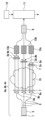
- FIG. 1 is a diagram showing a gas sensor according to a first embodiment
- FIG. 2 is a diagram showing absorption spectra of main gases.
- FIG. 3 is a graph showing the absorption spectrum of methane gas extracted from FIG. 2.
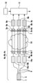
- FIG. 13 is a diagram showing a gas sensor according to a second embodiment.
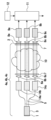
- FIG. 13 is a diagram showing a gas sensor according to a third embodiment.
- FIG. 13 is a diagram showing a modified example of the gas sensor according to the third embodiment.
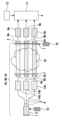
- FIG. 13 is a diagram showing a gas sensor according to a fourth embodiment.
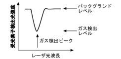
- FIG. 4 is a diagram showing the light intensity detected by a light receiving element.
- Embodiment 1. 1 is a diagram showing a gas sensor according to a first embodiment.
- One gain medium 3 is disposed between one mirror 1 and multiple semi-transparent mirrors 2a, 2b, and 2c.
- the mirror 1 and the semi-transparent mirror 2a are like a pair of mirrors and constitute a resonator 4a.
- the mirror 1 and the semi-transparent mirror 2b constitute a resonator 4b
- the mirror 1 and the semi-transparent mirror 2c constitute a resonator 4c.
- the distances between the mirror 1 and each of the semi-transparent mirrors 2a, 2b, and 2c are different from one another. Therefore, the mirror 1 and the multiple semi-transparent mirrors 2a, 2b, and 2c constitute multiple resonators 4a, 4b, and 4c having different resonator lengths from one another.
- the gain medium 3 is a semiconductor optical amplifier or an Er-doped fiber that amplifies the intensity of light passing through it. When a voltage is applied to the gain medium 3, broad natural light having a wide wavelength is emitted.
- the optical waveguide 5 branches the light emitted from the gain medium 3 into multiple lights.
- the optical waveguide 5 is an optical fiber or the like, and may be a waveguide formed on a substrate using Si or SiO 2.
- the optical waveguide 5 and the gain medium 3 may be directly connected, or a lens or an MMI (Multimode Interferometer) coupler may be introduced between them.
- the light emitted from the optical waveguide 5 into the air is emitted at a certain angle due to the refractive index difference.
- the lenses 6a, 6b, and 6c convert the multiple lights emitted from the optical waveguide 5 into parallel collimated lights and provide them to the multiple resonators 4a, 4b, and 4c, respectively.
- each resonator 4a, 4b, 4c with different resonator lengths simultaneously generate multiple laser lights with different wavelengths from the light emitted from the gain medium 3.
- Each laser light has a narrow spectral linewidth. Note that if the resonator lengths are similar and the oscillation wavelengths are close, interference may occur and stable laser light may not be obtained.
- a gas cell 7 made of transparent glass or the like is inserted inside the multiple resonators 4a, 4b, 4c.
- the optical system including the gain medium 3, resonators 4a, 4b, 4c, and lenses 6a, 6b, 6c, etc. are hermetically sealed inside a case, and the inside of the gas cell 7 is exposed to the outside.
- the lenses 6a, 6b, 6c and lenses 8a, 8b, 8c may also function as partitions to the gas cell 7.
- the windows of the resonators 4a, 4b, 4c may also serve as the two parallel surfaces of the gas cell 7.
- Lenses 8a, 8b, and 8c converge the multiple laser beams that have passed through semi-transparent mirrors 2a, 2b, and 2c onto the input surfaces of light-receiving elements 9a, 9b, and 9c. If there is an optical waveguide in front of the light-receiving elements 9a, 9b, and 9c, lenses 6a, 6b, and 6c adjust the beam diameter to converge the light onto the optical waveguide.
- the light-receiving elements 9a, 9b, and 9c each detect the multiple laser beams.
- the gas cell 7 is provided with the gas to be measured 10, and multiple laser beams are made to interfere with the gas to be measured 10 inside the resonators 4a, 4b, and 4c. If the gas to be measured 10 contains gas components that have an absorption spectrum according to the wavelength of the laser beam, the intensity of the laser beam decreases.
- the detection unit 11 detects the absorption of multiple laser beams by the measured gas 10 from the output of the light receiving elements 9a, 9b, and 9c, and determines the gas type and concentration of the measured gas 10. Specifically, the gas type can be determined from the wavelength of the laser beam with reduced intensity, and the gas concentration can be determined from the amount of change in intensity of the laser beam.
- the intensities of laser light of multiple wavelengths are detected by a photoreceiver.
- the detection results of the light receiving elements 9a, 9b, and 9c are stored in advance in the memory unit 12 as reference data.
- the detection unit 11 compares the detection results of the light receiving elements 9a, 9b, and 9c with the reference data to determine the gas type and gas concentration of the measured gas 10.
- the intensity of the laser light may be detected using a standard sample whose gas type and gas concentration are known, and recorded as reference data. In this case, the measured gas 10 is introduced into the sensor, and the intensity of the laser light detected is compared with the reference data to calculate the gas type and gas concentration.
- Figure 2 shows the absorption spectra of major gases.
- Figure 3 shows the absorption spectrum of methane gas extracted from Figure 2.
- Figure 2 shows the rough band in which the absorption spectrum exists, and in reality, as shown in Figure 3, multiple fine absorption spectra exist within the band.
- multiple resonators 4a, 4b, and 4c with different resonator lengths, it is possible to obtain laser light of multiple wavelengths even with a single gain medium 3.
- Multiple laser lights are made to interfere with the measured gas 10 inside the multiple resonators 4a, 4b, and 4c, and multiple gas types can be determined by detecting the absorption of the multiple laser lights by the measured gas 10. Since only one expensive gain medium 3 is required and only one set of components such as a power supply circuit that drives the gain medium 3 is required, a small and inexpensive gas sensor can be realized.
- the gas sensor according to this embodiment is used, for example, as an odor sensor.
- the resonator lengths of the resonators 4a, 4b, and 4c are set so as to generate laser light with a wavelength corresponding to the gas to be detected. If there are three resonators 4a, 4b, and 4c, three types of gases, for example, ammonia, carbon dioxide, and nitrous oxide, can be detected. Furthermore, if five types of gases including methane and hydrogen chloride are to be detected, five resonators should be used.
- the oscillation wavelength of the laser light is determined by the resonator length and the refractive index of the light path, but strictly speaking the refractive index changes depending on the type and concentration of gas in the light path, so the oscillation wavelength changes slightly. However, since gas detection in everyday life is assumed, this is not thought to have a significant effect. When detecting high concentration gases, gas concentrations can be detected with high accuracy by combining this with a peak search using wavelength scanning.
- Embodiment 2. 4 is a diagram showing a gas sensor according to the second embodiment.
- the optical switches 13a, 13b, and 13c switch whether or not to pass the incident light.
- the laser lights of different wavelengths coming out of the three resonators 4a, 4b, and 4c are passed in order by the optical switches 13a, 13b, and 13c, respectively, and made to enter one light receiving element 9.
- the identification of the gas type is time-shared. This makes it possible to reduce the number of light receiving elements 9.
- the other configurations and effects are the same as those of the first embodiment.
- Embodiment 3. 5 is a diagram showing a gas sensor according to a third embodiment.
- the mirror 1 is spaced apart from the semi-transparent mirrors 2a, 2b, and 2c at the same interval.
- a plurality of delay elements 14a, 14b, and 14c are provided in the resonators 4a, 4b, and 4c, respectively.
- the refractive indices of the delay elements 14a, 14b, and 14c are different from one another.
- the delay devices 14a, 14b, and 14c are elements used for signal modulation in optical communication, and are made of an insulator such as LiNbO3 , or a semiconductor such as InP or Si.
- the delay devices made of LiNbO3 adjust the refractive index by the Pockels effect caused by the application of a voltage.
- the delay devices made of InP or Si adjust the refractive index by the thermo-optic effect or carrier plasma effect caused by a current.
- FIG. 6 is a diagram showing a modified example of the gas sensor according to the third embodiment.
- the positions of the multiple semi-transparent mirrors 2a, 2b, and 2c are shifted to roughly align with the target oscillation wavelength, and the resolution is increased by fine-tuning the delay units 14a, 14b, and 14c.
- the delay units 14a, 14b, and 14c have sufficient dynamic range and resolution.
- the oscillation wavelength can be controlled by the delay units 14a, 14b, and 14c, so that oscillation wavelength control by the position of the semi-transparent mirror is not necessary. Therefore, the number of semi-transparent mirrors 2 can be reduced to one regardless of the number of laser light wavelengths to be handled. In other words, one mirror 1 and one semi-transparent mirror 2 facing each other are shared by the multiple resonators 4a, 4b, and 4c.
- Embodiment 4. 7 is a diagram showing a gas sensor according to a fourth embodiment.
- the temperature adjustment unit 15 adjusts the temperature of the gain medium 3 to adjust the refractive index of the gain medium 3.
- the temperature adjustment unit 15 may be, for example, a Peltier element or a current source for temperature adjustment using the self-heating of the semiconductor amplifier.
- the position adjustment unit 16 is a piezoelectric element or MEMS that physically moves the semi-transparent mirror 2, and adjusts the position of the semi-transparent mirror 2.
- the position adjustment unit 16 may be configured to adjust the positions of the semi-transparent mirrors 2a, 2b, and 2c individually. The other configurations are the same as those of the first to third embodiments.
- Figure 8 shows the light intensity detected by the light receiving element.
- the difference between the gas detection peak generated by the absorption of the laser light by the measured gas 10 and the background level of the sensor including dirt or aging is detected.
- the temperature of the gain medium 3 is adjusted to determine the required range of oscillation wavelength.
- the positions of the semi-transparent mirrors 2, 2a, 2b, 2c are adjusted to operate the laser light within the range of the absorption spectrum of the measured gas 10.
- the delay devices 14a, 14b, 14c are adjusted to set the oscillation wavelengths of the resonators 4a, 4b, 4c individually.
- the accuracy of gas detection can be improved by adjusting the temperature of the gain medium 3, the positions of the semi-transparent mirrors 2, 2a, 2b, 2c, or the refractive index of the delay devices 14a, 14b, 14c to scan the oscillation wavelengths of the resonators 4a, 4b, 4c.
Landscapes
- Physics & Mathematics (AREA)
- Spectroscopy & Molecular Physics (AREA)
- Analytical Chemistry (AREA)
- Health & Medical Sciences (AREA)
- Life Sciences & Earth Sciences (AREA)
- Chemical & Material Sciences (AREA)
- Biochemistry (AREA)
- General Health & Medical Sciences (AREA)
- General Physics & Mathematics (AREA)
- Immunology (AREA)
- Pathology (AREA)
- Optics & Photonics (AREA)
- Investigating Or Analysing Materials By Optical Means (AREA)
Abstract
Description
図1は、実施の形態1に係るガスセンサを示す図である。1つのミラー1と複数の半透過ミラー2a,2b,2cとの間に1つの利得媒体3が配置されている。ミラー1と半透過ミラー2aは合わせ鏡のようになっており共振器4aを構成する。同様にミラー1と半透過ミラー2bは共振器4bを構成し、ミラー1と半透過ミラー2cは共振器4cを構成する。ただし、ミラー1と半透過ミラー2a,2b,2cのそれぞれとの間隔は互いに異なる。従って、ミラー1と複数の半透過ミラー2a,2b,2cは、互いに異なる共振器長を有する複数の共振器4a,4b,4cを構成する。
図4は、実施の形態2に係るガスセンサを示す図である。光スイッチ13a,13b,13cは、入射した光を通過させるか否かを切り替える。3つの共振器4a,4b,4cから出てくる異なる波長のレーザ光をそれぞれ光スイッチ13a,13b,13cが順番に通過させて1つの受光素子9に入射させる。即ち、ガス種の同定を時分割する。これにより、受光素子9の数を削減することができる。その他の構成及び効果は実施の形態1と同様である。
図5は、実施の形態3に係るガスセンサを示す図である。ミラー1と複数の半透過ミラー2a,2b,2cとのそれぞれの間隔は同じである。複数の遅延器14a,14b,14cがそれぞれ複数の共振器4a,4b,4cの中に設けられている。遅延器14a,14b,14cの屈折率は互いに異なる。
図7は、実施の形態4に係るガスセンサを示す図である。温度調整部15は、利得媒体3の屈折率を調整するために利得媒体3の温度を調整する。利得媒体3が半導体増幅器の場合には、温度調整15は例えばペルチェ素子でもよいし、半導体増幅器の自己発熱を利用した温度調整のための電流源でもよい。位置調整部16は、半透過ミラー2を物理的に移動させるピエゾ素子又はMEMSであり、半透過ミラー2の位置を調整する。なお、位置調整部16が半透過ミラー2a,2b,2cの位置を個別に調整するように構成することもできる。その他の構成は実施の形態1-3と同様である。
Claims (8)
- 1つの利得媒体と、
互いに異なる共振器長を有し、前記利得媒体の出射光から互いに異なる波長を有する複数のレーザ光を同時に発生させる複数の共振器と、
前記複数のレーザ光を検出する受光素子とを備え、
前記複数の共振器の内部で前記複数のレーザ光を被測定ガスと干渉させることを特徴とするガスセンサ。 - 前記受光素子の出力から前記被測定ガスによる前記複数のレーザ光の吸収を検出することで前記被測定ガスのガス種を判定する検出部を更に備えることを特徴とする請求項1に記載のガスセンサ。
- 参照データを記憶する記憶部を更に備え、
前記検出部は、前記受光素子の検出結果と前記参照データを比較して前記被測定ガスのガス種又は濃度を判定することを特徴とする請求項2に記載のガスセンサ。 - 前記利得媒体の出射光を複数の光に分岐する光導波路と、
前記複数の光をそれぞれコリメート光に変換して前記複数の共振器にそれぞれ提供するレンズとを更に備えることを特徴とする請求項1~3の何れか1項に記載のガスセンサ。 - 前記複数の共振器から出てくるレーザ光を順番に前記受光素子に入射させる光スイッチを更に備えることを特徴とする請求項1~4の何れか1項に記載のガスセンサ。
- 前記複数の共振器の中にそれぞれ設けられ、屈折率が互いに異なる複数の遅延器を更に備えることを特徴とする請求項1~5の何れか1項に記載のガスセンサ。
- 向かい合わせになった1つのミラーと1つの半透過ミラーを前記複数の共振器が共有していることを特徴とする請求項6に記載のガスセンサ。
- 前記利得媒体の温度を調整する温度調整部と、
前記複数の共振器のミラーの位置を調整する位置調整部とを更に備えることを特徴とする請求項1~7の何れか1項に記載のガスセンサ。
Priority Applications (4)
| Application Number | Priority Date | Filing Date | Title |
|---|---|---|---|
| CN202280101024.9A CN120129828A (zh) | 2022-11-07 | 2022-11-07 | 气体传感器 |
| JP2024556851A JP7726410B2 (ja) | 2022-11-07 | 2022-11-07 | ガスセンサ |
| PCT/JP2022/041407 WO2024100723A1 (ja) | 2022-11-07 | 2022-11-07 | ガスセンサ |
| US18/871,758 US20250341464A1 (en) | 2022-11-07 | 2022-11-07 | Gas sensor |
Applications Claiming Priority (1)
| Application Number | Priority Date | Filing Date | Title |
|---|---|---|---|
| PCT/JP2022/041407 WO2024100723A1 (ja) | 2022-11-07 | 2022-11-07 | ガスセンサ |
Publications (1)
| Publication Number | Publication Date |
|---|---|
| WO2024100723A1 true WO2024100723A1 (ja) | 2024-05-16 |
Family
ID=91032293
Family Applications (1)
| Application Number | Title | Priority Date | Filing Date |
|---|---|---|---|
| PCT/JP2022/041407 Ceased WO2024100723A1 (ja) | 2022-11-07 | 2022-11-07 | ガスセンサ |
Country Status (4)
| Country | Link |
|---|---|
| US (1) | US20250341464A1 (ja) |
| JP (1) | JP7726410B2 (ja) |
| CN (1) | CN120129828A (ja) |
| WO (1) | WO2024100723A1 (ja) |
Citations (6)
| Publication number | Priority date | Publication date | Assignee | Title |
|---|---|---|---|---|
| JP3304846B2 (ja) * | 1997-09-16 | 2002-07-22 | アロカ株式会社 | ガス測定装置及び同位体濃度比測定装置 |
| JP2011258828A (ja) * | 2010-06-10 | 2011-12-22 | Canon Inc | 光源装置及びこれを用いた撮像装置 |
| CN104697933A (zh) * | 2015-03-04 | 2015-06-10 | 中国科学院合肥物质科学研究院 | 三通道声学谐振腔光声光谱传感装置 |
| WO2020075246A1 (ja) * | 2018-10-10 | 2020-04-16 | 三菱電機株式会社 | レーザ装置 |
| US20210018430A1 (en) * | 2019-07-20 | 2021-01-21 | Dalian University Of Technology | Multi-cavity semi-open resonant photoacoustic cell and multi-gas simultaneous measurement system |
| CN114047136A (zh) * | 2021-11-09 | 2022-02-15 | 大连理工大学 | 一种高灵敏度组合光源式光声光谱多组分气体检测系统及方法 |
-
2022
- 2022-11-07 US US18/871,758 patent/US20250341464A1/en active Pending
- 2022-11-07 JP JP2024556851A patent/JP7726410B2/ja active Active
- 2022-11-07 CN CN202280101024.9A patent/CN120129828A/zh active Pending
- 2022-11-07 WO PCT/JP2022/041407 patent/WO2024100723A1/ja not_active Ceased
Patent Citations (6)
| Publication number | Priority date | Publication date | Assignee | Title |
|---|---|---|---|---|
| JP3304846B2 (ja) * | 1997-09-16 | 2002-07-22 | アロカ株式会社 | ガス測定装置及び同位体濃度比測定装置 |
| JP2011258828A (ja) * | 2010-06-10 | 2011-12-22 | Canon Inc | 光源装置及びこれを用いた撮像装置 |
| CN104697933A (zh) * | 2015-03-04 | 2015-06-10 | 中国科学院合肥物质科学研究院 | 三通道声学谐振腔光声光谱传感装置 |
| WO2020075246A1 (ja) * | 2018-10-10 | 2020-04-16 | 三菱電機株式会社 | レーザ装置 |
| US20210018430A1 (en) * | 2019-07-20 | 2021-01-21 | Dalian University Of Technology | Multi-cavity semi-open resonant photoacoustic cell and multi-gas simultaneous measurement system |
| CN114047136A (zh) * | 2021-11-09 | 2022-02-15 | 大连理工大学 | 一种高灵敏度组合光源式光声光谱多组分气体检测系统及方法 |
Also Published As
| Publication number | Publication date |
|---|---|
| JP7726410B2 (ja) | 2025-08-20 |
| CN120129828A (zh) | 2025-06-10 |
| JPWO2024100723A1 (ja) | 2024-05-16 |
| US20250341464A1 (en) | 2025-11-06 |
Similar Documents
| Publication | Publication Date | Title |
|---|---|---|
| US10883929B2 (en) | Optical absorption spectroscopy based gas analyzer systems and methods | |
| Waclawek et al. | Balanced-detection interferometric cavity-assisted photothermal spectroscopy | |
| CN109416318B (zh) | 光热干涉测量装置和方法 | |
| JP4693409B2 (ja) | キャビティリングダウン分光法用の光源を制御するためのシステム及び方法 | |
| US6980297B2 (en) | Wavelength monitor | |
| US4958354A (en) | Apparatus for stabilizing the intensity of light | |
| US5544186A (en) | Gas laser for emitting light modulated at two different wavelengths and an arrangement incorporating the gas laser to detect a gaseous substance | |
| CA2792032A1 (en) | Method and apparatus for the photo-acoustic identification and quantification of analyte species in a gaseous or liquid medium | |
| US9250130B2 (en) | Quantum cascade laser with autonomously aligned external cavity and related methods | |
| JP7726410B2 (ja) | ガスセンサ | |
| JPH0543983B2 (ja) | ||
| JP2659554B2 (ja) | 光強度相関装置 | |
| Hernandez-Cordero et al. | Fiber laser intra-cavity spectroscopy (FLICS) | |
| CN118671027A (zh) | 一种痕量气体检测系统及方法 | |
| US8290007B2 (en) | Apparatus and method for stabilizing frequency of laser | |
| JP2006507673A (ja) | ダイヤモンドエタロンを含む波長固定器 | |
| US20250208038A1 (en) | Measuring arrangements and methods for the detection of trace gases in a sample gas | |
| US20250146870A1 (en) | Reduction of optical interference signals by means of vibratory movements of optically active elements of a spectrometer | |
| JPH11274643A (ja) | 可変波長半導体レーザ光源 | |
| TW202532814A (zh) | 測定裝置 | |
| JPH05160467A (ja) | 半導体レーザーのモードホッピング検出装置 | |
| Zanetti et al. | CO2 Sensing Using Symmetrical Three-Wavelength Precompensated Current-Modulated Diode Laser Differential Absorption Lidar | |
| Vervoort et al. | Interferometrically Enhanced Intensity and Wavelength Modulation in Tunable Diode Laser Spectroscopy. Photonics 2024, 11, 740 | |
| JPH05312523A (ja) | 半導体レーザ測長器 | |
| JPH0789147B2 (ja) | 距離測定装置 |
Legal Events
| Date | Code | Title | Description |
|---|---|---|---|
| 121 | Ep: the epo has been informed by wipo that ep was designated in this application |
Ref document number: 22965050 Country of ref document: EP Kind code of ref document: A1 |
|
| WWE | Wipo information: entry into national phase |
Ref document number: 2024556851 Country of ref document: JP |
|
| WWE | Wipo information: entry into national phase |
Ref document number: 18871758 Country of ref document: US |
|
| WWE | Wipo information: entry into national phase |
Ref document number: 202280101024.9 Country of ref document: CN |
|
| WWP | Wipo information: published in national office |
Ref document number: 202280101024.9 Country of ref document: CN |
|
| NENP | Non-entry into the national phase |
Ref country code: DE |
|
| 122 | Ep: pct application non-entry in european phase |
Ref document number: 22965050 Country of ref document: EP Kind code of ref document: A1 |
|
| WWP | Wipo information: published in national office |
Ref document number: 18871758 Country of ref document: US |