WO2024095915A1 - レンズ集合体 - Google Patents
レンズ集合体 Download PDFInfo
- Publication number
- WO2024095915A1 WO2024095915A1 PCT/JP2023/038865 JP2023038865W WO2024095915A1 WO 2024095915 A1 WO2024095915 A1 WO 2024095915A1 JP 2023038865 W JP2023038865 W JP 2023038865W WO 2024095915 A1 WO2024095915 A1 WO 2024095915A1
- Authority
- WO
- WIPO (PCT)
- Prior art keywords
- lens assembly
- lens
- glass
- protective film
- main surface
- Prior art date
- Legal status (The legal status is an assumption and is not a legal conclusion. Google has not performed a legal analysis and makes no representation as to the accuracy of the status listed.)
- Ceased
Links
Images






Classifications
-
- G—PHYSICS
- G01—MEASURING; TESTING
- G01N—INVESTIGATING OR ANALYSING MATERIALS BY DETERMINING THEIR CHEMICAL OR PHYSICAL PROPERTIES
- G01N21/00—Investigating or analysing materials by the use of optical means, i.e. using sub-millimetre waves, infrared, visible or ultraviolet light
- G01N21/84—Systems specially adapted for particular applications
-
- G—PHYSICS
- G02—OPTICS
- G02B—OPTICAL ELEMENTS, SYSTEMS OR APPARATUS
- G02B3/00—Simple or compound lenses
Definitions
- This disclosure relates to a lens assembly comprising multiple glass lenses.
- Lens assemblies used in printers, scanners, inspection equipment, etc. are known (see, for example, Patent Document 1). This lens assembly is placed between an object to be irradiated with light from a light source and an object to be imaged.
- the lens assembly described in Patent Document 1 is composed of a first lens array and a second lens array stacked in the optical axis direction.
- the relative movement of the first lens array and the second lens array is restricted by a positioning portion, ensuring the optical characteristics of the lens assembly.
- Patent Document 1 does not address the above issues, and this poses problems from the standpoint of durability.
- the lens assembly according to the present disclosure is characterized in that it is a lens assembly arranged between an object to be irradiated with light from a light source and an image forming object, with the surface facing the object to be irradiated and the surface facing the image forming object being open, and is provided with a plurality of glass lenses formed in a columnar shape having a first main surface consisting of a flat surface facing the object to be irradiated, a second main surface consisting of a flat surface facing the image forming object, and a side surface connecting the first main surface and the second main surface, an adhesive member that bonds the side surfaces of the plurality of adjacent glass lenses, and a protective film that covers at least one of the first main surface and the second main surface.
- the lens assembly in this configuration is provided with a protective film that covers at least one of the first and second principal surfaces of the glass lens, thereby preventing tarnish on the first and second principal surfaces that are exposed to the outside air.
- This protective film is preferably provided on both the first and second principal surfaces, but may be provided on at least one of the first and second principal surfaces depending on the usage environment.
- the lens assembly is capable of preventing the growth of tarnish on the first and second principal surfaces that are exposed to the outside air, and ensuring good optical properties over a long period of time.
- the first and second principal surfaces that are covered with the protective film suppress the reflection of light on these principal surfaces, so there is no need to provide a separate anti-reflection film. In this way, a lens assembly in which light is less likely to be reflected on the lens surface and good optical properties can be ensured over a long period of time has been obtained.
- the refractive index differs between the center and the side in a cross section parallel to the first principal surface.
- the desired optical characteristics can be achieved even if the lens is columnar.
- Another characteristic feature is that the refractive index of the glass lens decreases from the center to the side in a cross section parallel to the first principal surface.
- the refractive index is made smaller from the center of the glass lens to the sides, as in this configuration, the light will converge toward the center, ensuring the desired amount of light even in a columnar shape.
- the glass lens is formed in a cylindrical shape.
- the glass lens is cylindrical as in this configuration, the light will converge smoothly and the desired optical characteristics can be achieved.
- the adhesive member is made of resin.
- the adhesive member is made of resin as in this configuration, the sides of the glass lens are adequately protected.
- Another characteristic feature is that the side surface is covered with the protective film at a portion adjacent to at least one of the first region of the adhesive member adjacent to the first main surface and the second region of the adhesive member adjacent to the second main surface.
- Another characteristic feature is that at least a portion of at least one of the first region and the second region adjacent to the side surface covered with the protective film is covered with the protective film.
- the refractive index of the protective film is equal to or greater than the refractive index of air and equal to or less than the refractive index of the center of the glass lens.
- the refractive index of the protective film is set to be equal to or greater than the refractive index of air and equal to or less than the refractive index of the center of the glass lens, as in this configuration, it is possible to suppress light reflection and ensure the amount of light that passes through the glass lens.
- the protective film includes spherical microparticles and an adhesive layer that is thinner than the microparticles.
- the air between the fine particles can lower the refractive index of the entire protective film, further suppressing light reflection.
- Another characteristic feature is that the first main surface is covered with the protective film.
- the paper dust absorbs moisture in the air or moisture during wiping, which can easily cause discoloration on the first and second principal surfaces, and this can impair the optical properties.
- discoloration is also likely to occur due to moisture during maintenance. This is particularly noticeable on the first principal surface facing the irradiated object. Therefore, discoloration on the first principal surface can be suppressed by covering the first principal surface with a protective film. In addition, when the first principal surface is covered with a protective film, the reflection of light incident on the first principal surface is suppressed.
- the amount of light incident on the lens assembly is sufficiently large without the need for a separate anti-reflection film, and the image of the irradiated object formed on the image forming object is sufficiently bright even without increasing the amount of light from the light source. As a result, it becomes easier to read the image information of the irradiated object.
- Another characteristic feature is that it can be used in testing equipment.
- the optical properties of the lens assembly can be maintained for a long period of time, so the performance of the inspection device can be maintained for a long period of time.
- FIG. 1 is a schematic configuration diagram of a line inspection device using a lens assembly according to an embodiment of the present invention.
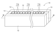
- 1 is a perspective view showing a lens assembly according to an embodiment of the present invention.
- 1 is a diagram showing the refractive index distribution of a glass rod and a glass lens.
- FIG. 2 is a diagram showing the adhesive material filled between a plurality of glass lenses after it has been hardened.
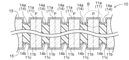
- 4 is a cross-sectional view taken along line IV-IV in FIG. 2.
- FIG. 4C is an enlarged view of part B in FIG. 4B.
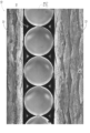
- 3 is a photograph of the lens assembly according to the example before a humidity resistance test.
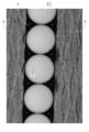
- 4 is a photograph of the lens assembly according to the example after a humidity resistance test.
- 13 is a photograph of a lens assembly according to a comparative example before a humidity resistance test.
- 13 is a photograph of a lens assembly according to a comparative example after a humidity resistance test.
- a lens assembly used in an inspection device will be described as an example of a lens assembly.
- the present invention is not limited to the following embodiment, and various modifications are possible without departing from the spirit of the present invention.
- FIG. 1 is a diagram for explaining a line inspection device 1 (an example of an inspection device) using a lens assembly 10 according to an embodiment of the present disclosure.
- the line inspection device 1 has an image sensor unit 2 built in, and the lens assembly 10 is used in the image sensor unit 2.
- the line inspection device 1 includes the image sensor unit 2, a conveyor 3 on which an object to be inspected 9 (an example of an object to be irradiated) is placed and transported on a transport surface 3a, and an image processing unit (not shown) that processes data read by the image sensor unit 2.
- FIG. 1 is a diagram for explaining a line inspection device 1 (an example of an inspection device) using a lens assembly 10 according to an embodiment of the present disclosure.
- the line inspection device 1 has an image sensor unit 2 built in, and the lens assembly 10 is used in the image sensor unit 2.
- the line inspection device 1 includes the image sensor unit 2, a conveyor 3 on which an object to be inspected 9 (an example of an object to be irradiated) is placed and transported on a
- FIG. 1 shows a cross-sectional view of the image sensor unit 2 cut along a plane perpendicular to the transport surface 3a of the conveyor 3 and parallel to the transport direction of the object to be inspected 9.
- the transport direction is the direction of the arrow in FIG. 1 (to the left on the paper).
- the image sensor unit 2 has a line-shaped light source 4 (an example of a light source) that irradiates light onto the object 9 to be inspected placed on the conveyor 3, a lens assembly 10 that collects reflected light from the object 9 to be inspected, a line image sensor 5 (an example of an image-forming object) that receives the light collected by the lens assembly 10, a substrate 6 on which the line image sensor 5 is mounted, and a housing 7 that houses these.
- the lens assembly 10 is disposed between the object 9 to be inspected and the line image sensor 5, and the surface facing the object 9 to be inspected (the surface having the first main surface 11a described below) and the surface facing the line image sensor 5 (the surface having the second main surface 11b described below) are open.
- the object 9 to be inspected is transported along the transport direction.
- the lens assembly 10 extends along a direction perpendicular to the transport direction of the object 9 to be inspected, and a row of multiple glass lenses 11 is arranged and integrated.
- the linear light source 4 is also long in a direction perpendicular to the transport direction, and a linear light is irradiated toward the object 9 to be inspected. Since a known LED or the like is used for the linear light source 4, a detailed description is omitted.
- the line image sensor 5 is configured by arranging multiple photoelectric conversion elements along a direction perpendicular to the transport direction of the substrate 6. Since the configuration of the photoelectric conversion elements is known, a detailed description is omitted.
- the lens assembly 10, the linear light source 4, and the line image sensor 5 are all arranged along a direction perpendicular to the transport direction, and the light irradiated from the linear light source 4 is reflected by the object 9 to enter the lens assembly 10, and is configured to be imaged on the light receiving surface 5a of the line image sensor 5.
- the housing 7 has the function of fixing the lens assembly 10, the line light source 4, and the line image sensor 5 so that they maintain the positional relationship described above.
- the lens assembly 10 is arranged so that its optical axis P is perpendicular to the transport surface 3a of the conveyor 3, and the line light source 4 is arranged so that its emitted light uniformly and most brightly illuminates an irradiation area including an intersection f between the optical axis P of the lens assembly 10 and the transport surface 3a of the conveyor 3.
- the line image sensor 5 is fixed to the housing 7 on the optical axis P so that the position of its light receiving surface 5a is in a substantially upright, life-size relationship with the intersection f via the lens assembly 10.
- the line inspection device 1 the light from the line-shaped light source 4 is irradiated onto the object 9 to be inspected through the conveyor 3, and the reflected light from the object 9 is collected by the lens assembly 10 and imaged on the light receiving surface 5a of the line image sensor 5, thereby reading the image information of the object 9 to be inspected.
- the conveyor 3 transports the object 9 to be inspected on the transport surface 3a, and when the object 9 to be inspected passes directly under the image sensor unit 2, the image sensor unit 2 reads the image information of the desired area of the object 9 to be inspected.
- the transport speed of the conveyor 3 is controlled by a control unit (not shown).
- a similar embodiment is a roll-to-roll method in which textiles or sheet-like objects to be inspected are directly transported by rolls without using the conveyor 3. Even in an embodiment using such a method, the image information of the desired area can be read by adjusting the distance between the image sensor unit 2 and the object 9 to be inspected.
- the working distance L0 of the lens assembly 10 shown in Fig. 1 is preferably 8 mm or more, more preferably 10 mm or more, even more preferably 15 mm or more, particularly preferably 20 mm or more, and particularly preferably 25 mm or more.
- the working distance L0 is, for example, 60 mm or less, may be 55 mm or less, or may be 50 mm or less.
- the aperture angle ⁇ C (not shown) of the lens assembly 10 is, for example, 3° to 22°, and preferably 4° to 12°.
- the lens assembly 10 constitutes a substantially erect life-size imaging system, and the working distance L1 is substantially equal to the working distance L0 .
- the lens assembly 10 is configured by sandwiching a plurality of cylindrical glass lenses 11 between a pair of side plates 12 and a pair of spacers 13, and filling the gaps between the glass lenses 11, the side plates 12, and the spacers 13 with an adhesive member 14. If the glass lenses 11 are cylindrical, light can be smoothly converged, and desired optical characteristics can be exhibited.
- the glass lenses 11 are Selfoc lenses ("Selfoc" is a registered trademark).
- the side plates 12 and the spacers 13 are made of FRP (Fiber Reinforced Plastics) having light absorbing properties.
- the adhesive member 14 is made of a resin of a color that does not transmit light (e.g., black), and fixes the plurality of glass lenses 11 by bonding the side surfaces 11c of the adjacent glass lenses 11 to each other. If the adhesive member 14 is made of a resin, the side surfaces 11c of the glass lenses 11 can be properly protected.
- a resin of a color that does not transmit light e.g., black
- Glass lens 11 (Selfoc lens) is manufactured by immersing a glass rod in a melt of nitrates or the like. By immersing the glass rod in a melt of nitrates or the like, the alkali metal ions in the glass rod are exchanged with ions in the nitrates or the like (ion exchange). As a result, the refractive index distribution in a cross section parallel to the first main surface 11a of glass lens 11 formed by ion exchanging the glass rod becomes parabolic. In other words, the refractive index is different at the center (optical axis P) and the side surface 11c inside glass lens 11.
- Figure 3 shows the refractive index distribution of (a) the glass rod before ion exchange and (b) glass lens 11, which is the glass rod after ion exchange.
- the refractive index distribution in a cross section parallel to the first main surface 11a of the glass lens 11 is constant near the optical axis P and near the side surface 11c
- the refractive index distribution in a cross section parallel to the first main surface 11a of the glass lens 11 is high near the optical axis P and decreases continuously in a parabolic shape toward the side surface 11c. This allows the glass rod to function as a lens (glass lens 11).
- the desired optical characteristics can be achieved even with a cylindrical glass lens 11.
- the refractive index of air is 1.00
- the refractive index of the center of the glass lens 11 is 1.40 to 1.65, preferably 1.45 to 1.63.
- the refractive index of the glass lens 11 near the optical axis P is 1.60.
- the glass lens 11 refers to a SELFOC lens in which the refractive index distribution in the glass rod is parabolic.
- the "center” refers to the area around the optical axis P of the glass lens 11, which is within one-third of the distance from the central axis (optical axis P) of the glass lens 11 to the outer peripheral surface (side surface 11c) of the lens in the radial direction (the radius of the glass lens 11).
- Glass lens 11 contains alkali metals, so when exposed to the outside air, the alkali metals dissolve and become carbonates, causing tarnish 16 on the glass surface. Tarnish 16 are spots that appear on the glass surface (see Figure 9).
- ion exchange is carried out to manufacture Selfoc lenses, and the composition of glass lens 11 tends to contain a large amount of alkali metals to promote ion exchange. This makes tarnish 16 even more likely to occur.
- the second main surface 11b of glass lens 11 is the surface of glass lens 11 opposite the first main surface 11a.
- tarnish 16 is likely to occur on the first main surface 11a and the second main surface 11b.
- a small gap is generated at the interface between adhesive member 14 and the side surface 11c of glass lens 11. If water penetrates into this gap, tarnish 16 may grow from the side surface 11c of glass lens 11, causing deterioration.
- the lens assembly 10 when the lens assembly 10 is used for visual inspection of a printed matter (illuminated matter) where scattering of paper dust and the like occurs, the paper dust absorbs moisture in the air or moisture during wiping, which can easily cause discoloration 16 on the first main surface 11a and the second main surface 11b, and there is a risk of impairing the optical properties.
- discoloration 16 when performing maintenance to remove paper dust, discoloration 16 is also likely to occur due to moisture during maintenance. This is particularly noticeable on the first main surface 11a that faces the printed matter. Therefore, in this embodiment, the parts of the lens assembly 10 that are exposed to the outside air are covered with a protective film 15. Details of the protective film 15 will be described later.
- one spacer 13 is attached to one end of one side plate 12.
- the side plate 12 is slightly inclined so that the spacer 13 is at the bottom, and a plurality of columnar glass rods are densely arranged on the side plate 12.
- the glass rods may be arranged in a single row as in this embodiment, or in multiple rows.
- the other spacer 13 is attached to the other end of the side plate 12.
- the other side plate 12 is placed on top of the spacer 13 to assemble the intermediate body of the lens assembly 10.
- the adhesive member 14 is filled in the gaps of the assembled intermediate body and hardened.
- the adhesive member 14 can be filled by, for example, supplying liquid resin from one end of the gap and sucking it from the other end, so that the gaps of the intermediate body can be completely and uniformly filled. After this, the filled liquid adhesive member 14 is hardened. Next, the glass rods integrated by the hardening of the adhesive member 14 are cut to a predetermined lens length, and both end faces of the cut ends (rod lens end faces) are polished.
- the first region 14a which is the end of the adhesive member 14 adjacent to the first main surface 11a, may recede toward the second main surface 11b in the direction along the optical axis P.
- the second region 14b which is the end of the adhesive member 14 adjacent to the second main surface 11b, may recede toward the first main surface 11a in the direction along the optical axis P.
- the adhesive member 14 and the side surface 11c of the glass lens 11 may not be properly bonded, and a gap may occur between the adhesive member 14 and the side surface 11c of the glass lens 11. In these cases, the side surface 11c between the first main surface 11a and the first region 14a, and the side surface 11c between the second main surface 11b and the second region 14b are not coated with the adhesive member 14 and are exposed.
- a protective film 15 is formed to cover the first principal surface 11a, the side surface 11c, and the first region 14a, and a protective film 15 is also formed to cover the second principal surface 11b, the side surface 11c, and the second region 14b.
- the protective film 15 is formed by applying a liquid protective liquid by a known method such as spray coating, roll coating, dip coating, or bar coating, and then drying and hardening the liquid. This completes the lens assembly 10.
- the protective film 15 to cover the first main surface 11a, the side surface 11c, and the first region 14a as well as the second main surface 11b, the side surface 11c, and the second region 14b in this manner, reflection and diffusion of light are prevented, and malfunction of the device can be prevented.
- the protective film 15 can prevent the lens assembly 11 from being exposed to the outside air and causing discoloration 16.
- the optical characteristics of the lens assembly 10 can be maintained for a long period of time, so the performance of the line inspection device 1 can be maintained for a long period of time.
- the protective film 15 is formed to cover the first main surface 11a, the side surface 11c, and the first region 14a, and also to cover the second main surface 11b, the side surface 11c, and the second region 14b, so that reflection of light on the first main surface 11a and the second main surface 11b is suppressed.
- the line inspection device 1 can easily read the image information of the object to be inspected 9.
- the protective film 15 includes spherical silicon oxide particles 15a (an example of fine particles) and a binder 15b (an example of an adhesive layer) made of silicon oxide.
- FIG. 5 is an enlarged view of region B in FIG. 4B.
- the diameter of the silicon oxide particles 15a is 100 nm to 500 nm, preferably 100 nm to 300 nm, more preferably 100 nm to 200 nm, and further preferably more than 100 nm to 150 nm or less. In this embodiment, the diameter of the silicon oxide particles 15a is, for example, 120 nm.
- the thickness (film thickness) of the binder 15b is 10 nm to 300 nm, preferably 10 nm to 200 nm, and more preferably 10 nm to 70 nm.
- the film thickness of the binder 15b is preferably equal to or less than the radius of the silicon oxide particle 15a. In this embodiment, the film thickness of the binder 15b is equal to, for example, the radius of the silicon oxide particle 15a.
- the film thickness of the binder 15b is 60 nm. That is, the film thickness of the binder 15b is smaller than the diameter of the silicon oxide particle 15a. In other words, the silicon oxide particle 15a protrudes from the binder 15b. Therefore, the film thickness of the entire protective film 15 is equal to, for example, the diameter of the silicon oxide particle 15a. Specifically, if the diameter of the silicon oxide particle 15a is 120 nm, the film thickness of the entire protective film 15 is 120 nm.
- the refractive index of the silicon oxide particles 15a and the binder 15b is slightly smaller than that of the center of the glass lens 11. Therefore, when the refractive index of the protective film 15 is viewed in the direction away from the first main surface 11a along the optical axis P (film thickness direction), the protective film 15 contains both the silicon oxide particles 15a and the binder 15b from the first main surface 11a of the glass lens 11 to 60 nm, which is the film thickness of the binder 15b, along the optical axis P, so the refractive index of the protective film 15 is slightly smaller than the refractive index of 1.60 at the center of the glass lens 11.
- the protective film 15 consists only of silicon oxide particles 15a, and there is air between adjacent silicon oxide particles 15a. Since the silicon oxide particles 15a are spherical, the proportion of air in the protective film 15 increases from 60 nm to 120 nm. Therefore, the refractive index of the protective film 15 decreases from 60 nm to 120 nm. Therefore, the refractive index of the protective film 15 is greater than or equal to the refractive index of air and less than or equal to the refractive index of the center of the glass lens 11. Above 120 nm, the protective film 15 disappears and only air remains, so the refractive index is 1.00.
- the apparent refractive index of the protective film 15, which is made of silicon oxide particles 15a and binder 15b, both of which have a refractive index slightly smaller than that of the center of the glass lens 11, can be reduced.
- the proportion of light emitted from the glass lens 11 that is reflected by the second main surface 11b can be reduced, allowing more light to be emitted from the second main surface 11b.
- the line inspection device 1 the light emitted from the line light source 4 can be effectively used to form an image on the line image sensor 5.
- the embodiment of the lens assembly 10 according to the present disclosure can be applied to lenses other than the glass lens 11.
- the surface of the plastic lens can be appropriately protected and deterioration over time can be suppressed.
- materials for plastic lenses include translucent acrylic resin, polycarbonate resin, polyolefin resin, silicone resin, etc.
- the lens assembly according to the comparative example does not have a protective film 15 on the lens assembly 10, and the first principal surface 11a and the second principal surface 11b are exposed to the outside air.
- the only difference between the example and the comparative example is the presence or absence of the protective film 15; the glass lens 11 is the same.
- one spacer 13 was attached to one end of one side plate 12.
- the side plate 12 was then tilted slightly so that the spacer 13 was at the bottom, and multiple columnar glass rods were densely arranged in a row on the side plate 12.
- the other spacer 13 was attached to the other end of the side plate 12.
- the other side plate 12 was placed on top of that to assemble an intermediate body of the lens assembly 10.
- An adhesive material 14 was then filled in the gaps in the assembled intermediate body and hardened, fixing the multiple glass rods between the two side plates 12.
- the glass rods integrated by the curing of the adhesive member 14 were cut to a predetermined lens length, and both cut end faces (rod lens end faces) were polished to obtain glass lenses 11 according to the example and comparative example.
- a protective film 15 was formed so as to cover the first main surface 11a, the side surface 11c, and the first region 14a, and a protective film 15 was formed so as to cover the second main surface 11b, the side surface 11c, and the second region 14b, completing the lens assembly 10.
- Table 1 shows the working distance L 1 , lens length Z, conjugate length TC, field of view radius X 0 , aperture angle ⁇ C , refractive index distribution constant g [mm ⁇ 1 ], and central refractive index n 0 , which is the refractive index at the center of the glass lens 11, of this glass lens 11 (see also FIG. 1 ).
- the refractive index was measured in accordance with JIS B7071 (2018).
- the hydrolyzable silicon compound may be SiX 4.
- X is at least one of the group consisting of an alkoxyl group, an acetoxy group, an alkenyloxy group, an amino group, and a halogen atom.
- the hydrolyzable silicon compound may also be RSiY3 having a hydrophobic group directly bonded to silicon.
- Y is at least one selected from the group consisting of an alkoxy group, an acetoxy group, an alkenyloxy group, an amino group, and a halogen atom.
- a coating liquid was obtained by mixing and stirring 16.0 g of the above-mentioned stock solution A, 5.0 g of propylene glycol (solvent), 78.5 g of 1-methoxy-2-propanol (solvent), 0.4 g of an aqueous aluminum chloride solution (concentration 47.6% by mass as AlCl3 , prepared by dissolving reagent-grade aluminum chloride hexahydrate (manufactured by Sigma-Aldrich) in deionized water), and 0.1 g of KP-112 (Shin-Etsu Chemical Co., Ltd., polyether-type surface modifier, 50% by mass, 1-methoxy-2-propanol solution).
- the above-mentioned coating liquid was applied by dip coating to the entire surfaces on both sides of the glass lens 11 fixed with the adhesive member 14 (the first main surface 11a, the second main surface 11b, the side surface 11c, the first region 14a, and the second region 14b shown in FIG. 4B), forming a coating film, and this coating film was heated at 200°C for 1800 seconds to form a protective film 15. In this way, the lens assembly 10 according to the embodiment was obtained.
- FIG. 6 is a photograph of the first main surfaces 11a of the glass lenses 11 constituting the lens assembly 10 according to the embodiment before the humidity test.
- FIG. 7 is a photograph of the first main surfaces 11a of the glass lenses 11 constituting the lens assembly 10 according to the embodiment after the humidity test.
- FIG. 8 is a photograph of the first main surfaces 11a of the glass lenses 11 constituting the lens assembly according to the comparative example before the humidity test.
- FIG. 9 is a photograph of the first main surfaces 11a of the glass lenses 11 constituting the lens assembly according to the comparative example after the humidity test.
- the lens assembly 10 according to the embodiment can ensure good optical characteristics for a long period of time.
- the lens assembly 10 has a protective film 15 that covers the first main surface 11a and side surface 11c of the glass lens 11, and the first region 14a, and also covers the second main surface 11b and side surface 11c of the glass lens 11, and the second region 14b. Therefore, even if exposed to high temperature and high humidity for a long time, a tarnish 16 does not occur on the surface.
- the protective film 15 can reduce the reflectance of light on the first main surface 11a without providing a separate protective film. As a result, the lens assembly 10 is less likely to reflect light on the surface of the glass lens 11, and good optical characteristics can be ensured for a long period of time. As a result, the performance of the line inspection device 1 can be maintained for a long period of time.
- the protective film 15 of this embodiment has water resistance and anti-reflection properties.
- anti-reflection films having anti-reflection properties are often formed by placing the lens assembly 10 in a vacuum.
- the protective film 15 of this embodiment is formed by liquid phase deposition as described above, so it can be formed without placing the lens assembly 10 in a vacuum.
- the protective film 15 formed by liquid phase deposition has better film-forming properties on the side surface 11c of the glass lens 11 than protective films formed by gas phase deposition or the like. That is, since gas phase deposition is usually performed from one direction, it is not possible to form a sufficient film on the shadowed parts.
- liquid phase deposition can be performed on all parts that are wetted by the liquid, which is particularly advantageous for deposition that requires the liquid to wrap around the side surface 11c, such as the glass lens 11.
- the protective film 15 is formed to cover the first main surface 11a, the side surface 11c, the first region 14a, the second main surface 11b, the side surface 11c, and the second region 14b, but is not limited thereto.
- the protective film 15 may be formed only on the first main surface 11a, the side surface 11c, and the first region 14a, or only on the second main surface 11b, the side surface 11c, and the second region 14b.
- the protective film 15 may also be formed on at least one of the first main surface 11a and the side surface 11c, or the second main surface 11b and the side surface 11c.
- the protective film 15 may be formed on at least one of the first main surface 11a and the second main surface 11b.
- the protective film 15 may be formed at any location where the scorch 16 may occur.
- the particle size of the silicon oxide particles 15a, the film thickness of the binder 15b, and the content ratio of the silicon oxide particles 15a and the binder 15b are not limited to the above embodiment, and can be any configuration that provides the desired refractive index, i.e., the desired optical characteristics in the lens assembly 10.
- the proportion of the silicon oxide particles 15a in the protective film 15 is 35% to 90% by mass, preferably 40% to 90% by mass, and more preferably 45% to 85% by mass.
- the glass lenses 11 constituting the lens assembly 10 are arranged in a single row, but they may be arranged in two or more rows. In the case of two or more rows, it is preferable that the glass lenses 11 in adjacent rows are arranged in a staggered manner.
- the protective film 15 is formed to cover the first main surface 11a and the side surface 11c, and the entire first region 14a, and is also formed to cover the second main surface 11b and the side surface 11c, and the entire second region 14b, but this is not limited to this.
- the protective film 15 may be formed on at least a portion of at least one of the first region 14a and the second region 14b.
- the first region 14a is configured so that the center is recessed toward the second main surface 11b and the second region 14b is configured so that the center is recessed toward the first main surface 11a as the adhesive member 14 hardens, but this is not limited to the above.
- the adhesive member 14 may be configured so that the center of the first region 14a bulges toward the first main surface 11a and the center of the second region 14b bulges toward the second main surface 11b as the adhesive member 14 hardens.
- the first region 14a may be configured so that the center of the first region 14a is approximately flush with the first main surface 11a and the center of the second region 14b is approximately flush with the second main surface 11b. In these cases, if the adhesive member 14 does not adhere during hardening and a gap occurs between the adhesive member 14 and the side surface 11c of the glass lens 11, a protective liquid can enter the gap and form a protective film 15 on the side surface 11c.
- the glass lens 11 is cylindrical, but it may be rectangular or elliptical.
- This disclosure can be used for lens assemblies built into inspection equipment for visual inspection of printed matter, surface inspection of transparent films, defect inspection of steel plates, etc.
Landscapes
- Physics & Mathematics (AREA)
- General Physics & Mathematics (AREA)
- Health & Medical Sciences (AREA)
- Life Sciences & Earth Sciences (AREA)
- Chemical & Material Sciences (AREA)
- Analytical Chemistry (AREA)
- Biochemistry (AREA)
- General Health & Medical Sciences (AREA)
- Immunology (AREA)
- Pathology (AREA)
- Optics & Photonics (AREA)
- Lens Barrels (AREA)
Abstract
レンズ集合体(10)は、光源からの光が照射される被照射物と結像物の間に配置され、被照射物に対向する面及び結像物に対向する面が開放されている。レンズ集合体(10)は、被照射物に対向する平坦面からなる第1主面(11a)と、結像物に対向する平坦面からなる第2主面(11b)と、第1主面(11a)と第2主面(11b)とを接続する側面(11c)とを有する、柱状に形成された複数のガラスレンズ(11)と、隣り合う複数のガラスレンズ(11)の側面(11c)どうしを接着する接着部材(14)と、第1主面(11a)及び第2主面(11b)の少なくとも一方を覆う保護膜(15)と、を備えている。
Description
本開示は、複数のガラスレンズを備えたレンズ集合体に関する。
従来、プリンタ、スキャナー、検査機器等に用いられるレンズ集合体が知られている(例えば特許文献1参照)。このレンズ集合体は、光源からの光が照射される被照射物と結像物の間に配置される。
特許文献1に記載のレンズ集合体は、光軸方向に重ねられた第1レンズアレイ及び第2レンズアレイで構成されている。第1レンズアレイ及び第2レンズアレイは、位置決め部によってそれぞれの相対移動が規制され、レンズ集合体の光学特性を確保している。
ところで、紙粉等の飛散が生じる印刷物の外観検査や、高度な照明条件が必要な透明フィルムの表面検査、対象物のばらつきが大きい鋼板等の欠陥検査等の検査機器に内蔵されたレンズ集合体においては、ガラスレンズの一部が開放されており、外気に晒される場合がある。一般的にガラスレンズはアルカリ金属を含有しているため、外気に晒されると外気に含まれる水分によりアルカリ金属が溶出して炭酸塩となり、ガラス表面にヤケが生じる。このヤケによってガラスレンズが劣化し、光学特性が損なわれるおそれがある。特許文献1には、上記課題が記載されておらず、耐久性の観点から問題があった。
また、これらの検査機器にレンズ集合体を用いた場合、被検査物に衝突しない様に作動距離を大きくすることが望ましい。しかしながら、作動距離を大きくするとレンズ集合体に入射する光量が低下し、検査機器のラインイメージセンサで撮像される被検査物の像は明るくなり難い。レンズの作動距離又は開口角にもよるが、例えば、作動距離が1.5倍長いレンズを用いた場合、ラインイメージセンサに到達する光量が3割程度減少することがある。また、レンズ集合体のレンズ表面で光が反射した場合には、レンズ集合体に入射する光量は更に低下する。被検査物の像を明るくするために、例えば被検査物に照射する光源の光量を大きくすることが考えられる。しかし、光源の光量が大きいと、検査機器のランニングコストが高くなりやすく、光源の発熱量の増加に伴う被検査物への悪影響も懸念される。
そこで、レンズ表面で光が反射し難く、長期に亘って良好な光学特性を確保可能なレンズ集合体が望まれている。
本開示に係るレンズ集合体の特徴構成は、光源からの光が照射される被照射物と結像物の間に配置され、前記被照射物に対向する面及び前記結像物に対向する面が開放されたレンズ集合体であって、前記被照射物に対向する平坦面からなる第1主面と、前記結像物に対向する平坦面からなる第2主面と、前記第1主面と前記第2主面とを接続する側面とを有する、柱状に形成された複数のガラスレンズと、隣り合う複数の前記ガラスレンズの前記側面どうしを接着する接着部材と、前記第1主面及び前記第2主面の少なくとも一方を覆う保護膜と、を備えた点にある。
本構成のように、複数のガラスレンズの側面を接着部材で接着し、第1主面や第2主面を開放した状態にした場合、第1主面や第2主面が外気に晒される。その結果、第1主面や第2主面にヤケが生じやすい。特に、紙粉等の飛散が生じる印刷物(被照射物)の外観検査にレンズ集合体を使用した場合、第1主面や第2主面のヤケが成長しやすくなり、光学特性が損なわれるおそれがある。
そこで、本構成におけるレンズ集合体では、ガラスレンズの第1主面及び第2主面の少なくとも一方を覆う保護膜を備えることにより、外気に晒される第1主面や第2主面のヤケを防止することができる。この保護膜は、第1主面及び第2主面の両方に設けることが好ましいが、使用環境に応じて第1主面及び第2主面の少なくとも一方に設けてもよい。このように、外気に晒される第1主面や第2主面のヤケの成長を防止し、長期に亘って良好な光学特性を確保可能なレンズ集合体となっている。また、第1主面及び第2主面のうち保護膜で覆われた主面では、当該主面での光の反射が抑制されるので、別途反射防止膜を設ける必要がない。このように、レンズ表面で光が反射し難く、長期に亘って良好な光学特性を確保可能なレンズ集合体を得ることができた。
他の特徴構成は、前記ガラスレンズは、前記第1主面と平行な断面において、中心部と前記側面との屈折率が異なる点にある。
本構成のようにガラスレンズの中心部と側面との屈折率を異ならせれば、柱状であっても所望の光学特性を発揮できる。
他の特徴構成は、前記ガラスレンズは、前記第1主面と平行な断面において、前記中心部から前記側面に行くほど屈折率が小さくなる点にある。
本構成のようにガラスレンズの中心部から側面に行くほど屈折率を小さくすれば光が中心に向かって収束し、柱状であっても所望の光量を確保できる。
他の特徴構成は、前記ガラスレンズは、円柱状に形成されている点にある。
本構成のようにガラスレンズが円柱状であれば、光が滑らかに収束し、所望の光学特性を発揮できる。
他の特徴構成は、前記接着部材は樹脂で構成されている点にある。
本構成のように接着部材を樹脂で構成すれば、ガラスレンズの側面が適正に保護される。
他の特徴構成は、前記側面は、前記第1主面に隣り合う前記接着部材の第1領域及び前記第2主面に隣り合う前記接着部材の第2領域の少なくとも一方に隣接する部位が、前記保護膜で覆われている点にある。
上述した構成のように、複数のガラスレンズの側面を接着部材により接着すると、接着部材とガラスレンズの側面との界面に僅かな隙間が生じる。この隙間に水が浸入すると、ガラスレンズの側面からヤケが成長して劣化するおそれがある。そこで、本構成のように、接着部材の第1領域や第2領域に隣接するガラスレンズの側面及び接着部材が接着せず接着部材との間に隙間が生じたガラスレンズの側面に保護膜を設ければ、側面と接着部材との界面に水が浸入することを防止できる。また、側面の一部に接着部材に覆われていない部位があった場合でも、この保護膜によって外気に晒されてヤケが生じるといった不都合を防止できる。
他の特徴構成は、前記保護膜で覆われた前記側面に隣接する前記第1領域及び前記第2領域の少なくとも一方における少なくとも一部が前記保護膜で覆われている点にある。
光源からの光が接着部材に反射することにより光の拡散が生じる。その結果、レンズ集合体を用いる機器の誤作動に繋がるおそれがある。しかし、本構成のように、接着部材の表面を保護膜で覆うことにより、当該機器の誤作動を防止することができる。また、接着部材の表面を保護膜で覆うと、保護膜で覆われた箇所からの外気に含まれる水分の浸入を確実に防止できる。
他の特徴構成は、前記保護膜の屈折率は、空気の屈折率以上且つ前記ガラスレンズの前記中心部の屈折率以下である点にある。
本構成のように保護膜の屈折率を空気の屈折率以上且つガラスレンズの中心部の屈折率以下とすれば、光の反射を抑制して、ガラスレンズを通過する光量を確保することができる。
他の特徴構成は、前記保護膜は、球状の微粒子と、前記微粒子よりも小さい厚みで構成される接着層とを含んでいる点にある。
本構成のように微粒子を接着層に対して突出させれば、微粒子の間にある空気によって保護膜全体の屈折率を下げて、光の反射をより抑制することができる。
他の特徴構成は、前記第1主面が前記保護膜に覆われている点にある。
紙粉等の飛散が生じる被照射物の外観検査にレンズ集合体を使用した場合、紙粉が空気中の水分や拭取り時の水分を吸収し、この水分により第1主面や第2主面にヤケが発生しやすくなり、光学特性が損なわれるおそれがある。また、紙粉を除去するためのメンテナンスを行う際、メンテナンス時の水分によってもヤケが発生しやすい。これは、特に、被照射物に対向する第1主面において顕著である。そこで、第1主面を保護膜で覆うことにより、第1主面のヤケの発生を抑制することができる。また、第1主面が保護膜で覆われていると、第1主面に入射する光の反射が抑制される。そのため、別途反射防止膜を設けずともレンズ集合体に入射する光量が十分大きくなり、光源の光量を大きくしなくても結像物に結像された被照射物の像は十分明るくなる。その結果、被照射物の画像情報の読み取りを容易にする。
他の特徴構成は、検査機器に用いられる点である。
本構成のレンズ集合体を検査機器に用いると、長期に亘ってレンズ集合体の光学特性を確保可能なので、長期間に亘って検査機器の性能を維持することができる。
以下に、本開示に係るレンズ集合体の実施形態について、図面に基づいて説明する。本実施形態では、レンズ集合体の一例として、検査機器に用いられるレンズ集合体として説明する。ただし、以下の実施形態に限定されることなく、その要旨を逸脱しない範囲内で種々の変形が可能である。
〔ライン検査装置の構成〕
図1は、本開示の実施形態に係るレンズ集合体10を用いたライン検査装置1(検査機器の一例)を説明するための図である。ライン検査装置1はイメージセンサユニット2を内蔵しており、レンズ集合体10はイメージセンサユニット2に用いられている。ライン検査装置1は、イメージセンサユニット2、搬送面3aに被検査物9(被照射物の一例)が載置されて搬送されるコンベヤ3、及びイメージセンサユニット2によって読み取られたデータを処理する画像処理部(図示せず)等を備える。図1は、イメージセンサユニット2をコンベヤ3の搬送面3aに垂直且つ被検査物9の搬送方向に平行な面で切断したときの断面図を表している。搬送方向は、図1における矢印の方向(紙面の左方向)である。
図1は、本開示の実施形態に係るレンズ集合体10を用いたライン検査装置1(検査機器の一例)を説明するための図である。ライン検査装置1はイメージセンサユニット2を内蔵しており、レンズ集合体10はイメージセンサユニット2に用いられている。ライン検査装置1は、イメージセンサユニット2、搬送面3aに被検査物9(被照射物の一例)が載置されて搬送されるコンベヤ3、及びイメージセンサユニット2によって読み取られたデータを処理する画像処理部(図示せず)等を備える。図1は、イメージセンサユニット2をコンベヤ3の搬送面3aに垂直且つ被検査物9の搬送方向に平行な面で切断したときの断面図を表している。搬送方向は、図1における矢印の方向(紙面の左方向)である。
イメージセンサユニット2は、コンベヤ3上に載置された被検査物9に光を照射するライン状光源4(光源の一例)、被検査物9からの反射光を集光するレンズ集合体10、レンズ集合体10により集光された光を受けるラインイメージセンサ5(結像物の一例)、ラインイメージセンサ5を搭載した基板6、及びこれらを収容する筐体7を有する。レンズ集合体10は、被検査物9とラインイメージセンサ5との間に配置され、被検査物9に対向する面(後述する第1主面11aを有する面)及びラインイメージセンサ5に対向する面(後述する第2主面11bを有する面)が開放されている。
図1において、被検査物9は、搬送方向に沿って搬送される。レンズ集合体10は被検査物9の搬送方向に垂直な方向に沿って延出し、一列の複数のガラスレンズ11が配列されて一体化されている。ライン状光源4も搬送方向に垂直な方向に長く、被検査物9に向けてライン状の光が照射される。ライン状光源4には公知のLED等が用いられているので、詳細な説明は省略する。ラインイメージセンサ5は、基板6の搬送方向に垂直な方向に沿って複数の光電変換素子が配列されて構成されている。光電変換素子の構成は公知なので、詳細な説明は省略する。レンズ集合体10、ライン状光源4、及びラインイメージセンサ5は、いずれも搬送方向に垂直な方向沿って配置されており、ライン状光源4から照射された光が被検査物9で反射されてレンズ集合体10に入射し、ラインイメージセンサ5の受光面5aに結像されるように構成されている。
筐体7は、レンズ集合体10、ライン状光源4、及びラインイメージセンサ5を上述した位置関係を維持するように固定する機能を有している。レンズ集合体10は、その光軸Pがコンベヤ3の搬送面3aと垂直になるように配置され、さらにライン状光源4は、その照射光がレンズ集合体10の光軸Pとコンベヤ3の搬送面3aとの交点fを含む照射領域を均一且つ最も明るく照明する様に配置される。またラインイメージセンサ5は、光軸P上であり、且つ、その受光面5aの位置が交点fとレンズ集合体10を介して略正立等倍の関係となるように、筐体7に固定される。
ライン検査装置1においては、ライン状光源4からの照射光がコンベヤ3を通して被検査物9に照射され、被検査物9からの反射光をレンズ集合体10によって集光し、ラインイメージセンサ5の受光面5a上に結像することで被検査物9の画像情報を読み取る。具体的には、コンベヤ3が搬送面3a上の被検査物9を搬送して、被検査物9がイメージセンサユニット2の真下を通過するときに、イメージセンサユニット2は被検査物9の所望の領域の画像情報の読み取りを行う。コンベヤ3の搬送速度は、不図示の制御部により制御されている。なお、類似の実施形態としては、テキスタイルやシート状の被検査物を、コンベヤ3を用いることなくロールで直接搬送するロールツーロール方式がある。このような方式を用いた実施形態においても、イメージセンサユニット2と被検査物9との距離を調整すれば、所望の領域の画像情報を読み取ることができる。
図1に示されるレンズ集合体10の作動距離L0は、望ましくは8mm以上であり、より望ましくは10mm以上であり、更に望ましくは15mm以上であり、特に望ましくは20mm以上であり、とりわけ望ましくは25mm以上である。作動距離L0は、例えば、60mm以下であり、55mm以下であってもよく、50mm以下であってもよい。
また、レンズ集合体10の共役長TCは、TC=L0+Z+L1で定義され、例えば35mm~160mmであり、望ましくは40mm~150mmであり、より望ましくは48mm~100mmである。さらに、レンズ集合体10の開口角θC(不図示)は、例えば3°~22°であり、望ましくは4°~12°である。図1においてレンズ集合体10は、略正立等倍結像系を構成しており、作動距離L1は、作動距離L0と略等しい。
〔レンズ集合体の構成〕
次に、本実施形態に係るレンズ集合体10について説明する。レンズ集合体10は、図2に示されるように、円柱状の複数のガラスレンズ11を一対の側板12と一対のスペーサ13とで挟持し、ガラスレンズ11と側板12、スペーサ13との隙間に接着部材14を充填して構成されている。ガラスレンズ11が円柱状であれば、光が滑らかに収束し、所望の光学特性を発揮できる。ガラスレンズ11は、セルフォックレンズ(「セルフォック」は登録商標)である。側板12とスペーサ13とは、光吸収性を有するFRP(Fiber Reinforced Plastics)からなる。接着部材14は、光を透過しない色(例えば黒色)の樹脂からなり、隣り合うガラスレンズ11の側面11cどうしを接着することにより複数のガラスレンズ11を固定する。接着部材14を樹脂で構成すれば、ガラスレンズ11の側面11cを適正に保護することができる。
次に、本実施形態に係るレンズ集合体10について説明する。レンズ集合体10は、図2に示されるように、円柱状の複数のガラスレンズ11を一対の側板12と一対のスペーサ13とで挟持し、ガラスレンズ11と側板12、スペーサ13との隙間に接着部材14を充填して構成されている。ガラスレンズ11が円柱状であれば、光が滑らかに収束し、所望の光学特性を発揮できる。ガラスレンズ11は、セルフォックレンズ(「セルフォック」は登録商標)である。側板12とスペーサ13とは、光吸収性を有するFRP(Fiber Reinforced Plastics)からなる。接着部材14は、光を透過しない色(例えば黒色)の樹脂からなり、隣り合うガラスレンズ11の側面11cどうしを接着することにより複数のガラスレンズ11を固定する。接着部材14を樹脂で構成すれば、ガラスレンズ11の側面11cを適正に保護することができる。
ガラスレンズ11(セルフォックレンズ)は、ガラスロッドを硝酸塩等の融液に浸漬することにより製造される。ガラスロッドを硝酸塩等の融液に浸漬することにより、ガラスロッド中のアルカリ金属イオンと硝酸塩等の中のイオンとが交換される(イオン交換)。これにより、ガラスロッドをイオン交換して形成されたガラスレンズ11の第1主面11aに平行な断面における屈折率の分布が放物線状になる。すなわち、ガラスレンズ11の内部における中心(光軸P)と側面11cとの屈折率が異なっている。図3に、(a)イオン交換前のガラスロッドと、(b)イオン交換後のガラスロッドであるガラスレンズ11の屈折率分布を示す。図3(a)では、ガラスレンズ11の第1主面11aに平行な断面における屈折率分布が光軸P近傍と側面11c近傍とで屈折率が一定であるのに対し、図3(b)では、ガラスレンズ11の第1主面11aに平行な断面における屈折率分布が光軸P近傍で屈折率が高く、側面11cに近づくにつれて放物線状に連続的に屈折率が小さくなっている。これによりガラスロッドはレンズ(ガラスレンズ11)として機能するようになる。
このように、ガラスレンズ11の光軸P近傍と側面11cとの屈折率を異ならせれば、柱状のガラスレンズ11であっても所望の光学特性を発揮できる。また、ガラスレンズ11の光軸P近傍から側面11cに向かうほど屈折率を小さくすれば、光が光軸Pに向かって収束し、柱状のガラスレンズ11であっても所望の光量を確保できる。なお、空気の屈折率は1.00、ガラスレンズ11の中心部の屈折率は1.40~1.65であり、好ましくは1.45~1.63である。本実施形態においては、ガラスレンズ11の光軸P近傍の屈折率は1.60である。以下、ガラスレンズ11は、ガラスロッド内の屈折率分布が放物線状であるセルフォックレンズを意味するものとする。なお、「中心部」とは、ガラスレンズ11の光軸Pを含むその周囲であって、ガラスレンズ11の中心軸線(光軸P)から径方向で同レンズの外周面(側面11c)までの距離(ガラスレンズ11の半径)の3分の1以内の距離にある領域を意味する。
ガラスレンズ11は、アルカリ金属を含有しているので、外気に晒されるとアルカリ金属が溶出して炭酸塩となり、ガラス表面にヤケ16が生じる。ヤケ16とはガラス表面に現れる斑点状のものである(図9参照)。特に、セルフォックレンズ製造のためにはイオン交換が行われており、ガラスレンズ11の組成にはイオン交換が促進されるようにアルカリ金属が多く含まれる傾向にある。したがって、ヤケ16が更に発生しやすくなる。
仮に、複数のガラスレンズ11の側面11cを接着部材14で接着し、ガラスレンズ11の第1主面11aや第2主面11bを開放した状態にした場合、第1主面11aや第2主面11bが外気に晒される。ガラスレンズ11の第2主面11bとは、ガラスレンズ11における第1主面11aと反対側の面である。その結果、第1主面11aや第2主面11bにヤケ16が生じやすい。また、複数のガラスレンズ11の側面11cを接着部材14により接着すると、接着部材14とガラスレンズ11の側面11cとの界面に僅かな隙間が生じる。この隙間に水が浸入すると、ガラスレンズ11の側面11cからヤケ16が成長して劣化するおそれがある。特に、紙粉等の飛散が生じる印刷物(被照射物)の外観検査にレンズ集合体10を使用した場合、紙粉が空気中の水分や拭取り時の水分を吸収し、この水分により第1主面11aや第2主面11bにヤケ16が発生しやすくなり、光学特性が損なわれるおそれがある。また、紙粉を除去するためのメンテナンスを行う際、メンテナンス時の水分によってもヤケ16が発生しやすい。これは、特に、印刷物に対向する第1主面11aにおいて顕著である。そこで、本実施形態においては、レンズ集合体10の外気に晒された箇所を保護膜15で覆っている。保護膜15の詳細については後述する。
〔レンズ集合体の製造方法〕
次に、レンズ集合体10の製造方法について、図4A及び図4Bを用いて説明する。まず、一方の側板12の片側端部上に一方のスペーサ13を取り付ける。次に、該スペーサ13が下になるように前記側板12を若干傾斜させ、該側板12上に柱状のガラスロッドを複数、密に配列する。ガラスロッドは、本実施形態のように一列配列であってもよいし、複数列配列であってもよい。所定数のガラスロッドを配列した後、他方のスペーサ13を側板12の他方の端部に取り付ける。その上に、他方の側板12を重ねてレンズ集合体10の中間体を組み立てる。そして、組み立てた中間体の間隙部に接着部材14を充填させ硬化させる。接着部材14の充填は、例えば隙間部の一端側から液状樹脂を供給し、他端側から吸引することによって、中間体の間隙部に、全体的且つ均等に浸透充填させることができる。この後、充填した液状の接着部材14を硬化させる。次に、接着部材14の硬化により一体化された複数のガラスロッドを所定のレンズ長に切断し、切断した両端面(ロッドレンズ端面)を研磨する。
次に、レンズ集合体10の製造方法について、図4A及び図4Bを用いて説明する。まず、一方の側板12の片側端部上に一方のスペーサ13を取り付ける。次に、該スペーサ13が下になるように前記側板12を若干傾斜させ、該側板12上に柱状のガラスロッドを複数、密に配列する。ガラスロッドは、本実施形態のように一列配列であってもよいし、複数列配列であってもよい。所定数のガラスロッドを配列した後、他方のスペーサ13を側板12の他方の端部に取り付ける。その上に、他方の側板12を重ねてレンズ集合体10の中間体を組み立てる。そして、組み立てた中間体の間隙部に接着部材14を充填させ硬化させる。接着部材14の充填は、例えば隙間部の一端側から液状樹脂を供給し、他端側から吸引することによって、中間体の間隙部に、全体的且つ均等に浸透充填させることができる。この後、充填した液状の接着部材14を硬化させる。次に、接着部材14の硬化により一体化された複数のガラスロッドを所定のレンズ長に切断し、切断した両端面(ロッドレンズ端面)を研磨する。
このとき、図4Aに示されるように、接着部材14の、第1主面11aに隣接した端部である第1領域14aは、光軸Pに沿う方向で第2主面11bに近づく側に後退している場合がある。また、接着部材14の、第2主面11bに隣接した端部である第2領域14bは、光軸Pに沿う方向で第1主面11aに近づく側に後退している場合がある。さらに、接着部材14とガラスレンズ11の側面11cとがきちんと接着されず、接着部材14とガラスレンズ11の側面11cとの間に隙間が生じている場合がある。これらの場合、第1主面11aと第1領域14aとの間にある側面11c、及び第2主面11bと第2領域14bとの間にある側面11cは、接着部材14が塗布されておらず、露出した状態になっている。
この後、図4Bに示されるように、第1主面11a、側面11c、第1領域14aを覆うように保護膜15を形成すると共に、第2主面11b、側面11c、第2領域14bを覆うように保護膜15を形成する。保護膜15は、液状の保護液を、例えば、スプレーコーティング、ロールコーティング、ディップコーティング、バーコーティング等の公知の方法で塗布した後、乾燥、硬化させることにより形成する。これにより、レンズ集合体10が完成する。
光源からの光が接着部材14に反射することにより光の拡散が生じる。その結果、レンズ集合体10を用いる機器の誤作動に繋がるおそれがある。しかし、このように、第1主面11a、側面11c、第1領域14aを覆うと共に、第2主面11b、側面11c、第2領域14bを覆うように保護膜15を形成すると、光の反射、拡散が防止され、当該機器の誤作動を防止することができる。また、接着部材14の表面を保護膜15で覆うと、外気に晒される可能性があるレンズ集合体10の全域が保護膜15で覆われ、第1主面11a、第2主面11bのみならず、側面11c、さらには側面11cと接着部材14との界面も外気に含まれる水分に晒されることがないので、側面11cと接着部材14との界面に水分が浸入することを防止できる。これにより、ガラスレンズ11中のアルカリ金属が溶出してヤケ16を発生することを防止することができる。また、側面11cの一部に接着部材14に覆われていない部位があった場合でも、この保護膜15によって外気に晒されてヤケ16が生じるといった不都合を防止できる。これにより、長期にわたって良好な光学特性を確保可能なレンズ集合体10を得ることができる。また、レンズ集合体10用いたライン検査装置1においては、長期に亘ってレンズ集合体10の光学特性を確保可能なので、長期間に亘ってライン検査装置1の性能を維持することができる。
一般に、被検査物で反射された光がレンズ集合体のレンズに入射するときには、光の一部がレンズの表面で反射して、レンズを透過する光量は低下する。しかし、本実施形態のレンズ集合体10であれば、第1主面11a、側面11c、第1領域14aを覆うと共に、第2主面11b、側面11c、第2領域14bを覆うように保護膜15が形成されているので、第1主面11a及び第2主面11bにおける光の反射が抑制される。そのため、レンズ集合体10に入射する光量が十分大きくなり、ライン状光源4の光量を大きくしなくても、ライン検査装置1のラインイメージセンサ5の受光面5aに結像された被検査物9の像は十分明るくなる。その結果、ライン検査装置1は、被検査物9の画像情報を容易に読み取ることができる。
〔保護膜の構成〕
次に、保護膜15の構成について説明する。保護膜15は、図5に示されるように、球状の酸化シリコン粒子15a(微粒子の一例)と酸化シリコンからなるバインダ15b(接着層の一例)を含んでいる。図5は、図4Bの領域Bを拡大した図である。酸化シリコン粒子15aの直径は、100nm~500nmであり、望ましくは100nm~300nmであり、より望ましくは100nm~200nmであり、更に望ましくは100nmを超えて150nm以下である。本実施形態においては、酸化シリコン粒子15aの直径は、例えば120nmである。図5では、保護膜15で覆った第1主面11a、側面11c、第1領域14aを表している。図5では、酸化シリコン粒子15aとバインダ15bとが第1主面11a、側面11c、第1領域14aに接触している。バインダ15bは隣接する酸化シリコン粒子15aの間に配置されている。バインダ15bの厚さ(膜厚)は、10nm~300nmであり、望ましくは10nm~200nmであり、より望ましくは10nm~70nmである。バインダ15bの膜厚は、酸化シリコン粒子15aの半径以下であることが望ましい。本実施形態においては、バインダ15bの膜厚は、例えば、酸化シリコン粒子15aの半径に等しい。具体的には、酸化シリコン粒子15aの直径が120nmであれば、バインダ15bの膜厚は60nmである。すなわち、バインダ15bの膜厚は酸化シリコン粒子15aの直径よりも小さい。換言すると、酸化シリコン粒子15aは、バインダ15bから突出している。このため、保護膜15全体の膜厚は、例えば、酸化シリコン粒子15aの直径に等しい。具体的には、酸化シリコン粒子15aの直径が120nmであれば、保護膜15全体の膜厚は120nmである。
次に、保護膜15の構成について説明する。保護膜15は、図5に示されるように、球状の酸化シリコン粒子15a(微粒子の一例)と酸化シリコンからなるバインダ15b(接着層の一例)を含んでいる。図5は、図4Bの領域Bを拡大した図である。酸化シリコン粒子15aの直径は、100nm~500nmであり、望ましくは100nm~300nmであり、より望ましくは100nm~200nmであり、更に望ましくは100nmを超えて150nm以下である。本実施形態においては、酸化シリコン粒子15aの直径は、例えば120nmである。図5では、保護膜15で覆った第1主面11a、側面11c、第1領域14aを表している。図5では、酸化シリコン粒子15aとバインダ15bとが第1主面11a、側面11c、第1領域14aに接触している。バインダ15bは隣接する酸化シリコン粒子15aの間に配置されている。バインダ15bの厚さ(膜厚)は、10nm~300nmであり、望ましくは10nm~200nmであり、より望ましくは10nm~70nmである。バインダ15bの膜厚は、酸化シリコン粒子15aの半径以下であることが望ましい。本実施形態においては、バインダ15bの膜厚は、例えば、酸化シリコン粒子15aの半径に等しい。具体的には、酸化シリコン粒子15aの直径が120nmであれば、バインダ15bの膜厚は60nmである。すなわち、バインダ15bの膜厚は酸化シリコン粒子15aの直径よりも小さい。換言すると、酸化シリコン粒子15aは、バインダ15bから突出している。このため、保護膜15全体の膜厚は、例えば、酸化シリコン粒子15aの直径に等しい。具体的には、酸化シリコン粒子15aの直径が120nmであれば、保護膜15全体の膜厚は120nmである。
本実施形態において、酸化シリコン粒子15a及びバインダ15bの屈折率は、ガラスレンズ11の中心部の屈折率よりもやや小さい。そのため、保護膜15の屈折率を光軸Pに沿って第1主面11aから離れる方向(膜厚方向)に見ると、ガラスレンズ11の第1主面11aから光軸Pに沿ってバインダ15bの膜厚である60nmまでの間では、保護膜15は酸化シリコン粒子15aとバインダ15bの両方を含んでいるので、保護膜15の屈折率は、ガラスレンズ11の中心部の屈折率1.60よりやや小さい。その後、60nmから120nmまでは、保護膜15は酸化シリコン粒子15aだけになり、隣接する酸化シリコン粒子15aの間には空気がある。酸化シリコン粒子15aは球体状であるため、60nmから120nmに向かうにつれて、保護膜15に占める空気の割合が多くなる。そのため、60nmから120nmに向かうにつれて、保護膜15の屈折率は低下していく。したがって、保護膜15としての屈折率は、空気の屈折率以上且つガラスレンズ11の中心部の屈折率以下である。120nm以上は、保護膜15がなくなり空気だけになるので、屈折率は1.00である。
保護膜15を上記のように構成することにより、共に屈折率がガラスレンズ11の中心部の屈折率よりもやや小さい酸化シリコン粒子15aとバインダ15bからなる保護膜15の見かけの屈折率を小さくすることができる。これにより、空気とガラスレンズ11との間の屈折率の変化を緩やかにできるので、ガラスレンズ11に入射する光が第1主面11aで反射する割合を低減することができ、より多くの光をガラスレンズ11内に入射させることができる。また、ガラスレンズ11から出射される光が第2主面11bで反射される割合を低減することができ、より多くの光を第2主面11bから出射させることができる。このように、保護膜15の屈折率がガラスレンズ11の中心部の屈折率よりも小さければ、反射防止効果が生じて好ましい。したがって、ライン検査装置1において、ライン状光源4から出射される光を有効に活用してラインイメージセンサ5に結像させることができる。
本開示に係るレンズ集合体10の実施形態は、ガラスレンズ11以外にも適用可能である。例えば、樹脂製レンズに適用した場合、樹脂製レンズの表面を適切に保護し、また、経時劣化を抑制することができる。樹脂製レンズの材料としては、例えば、透光性があるアクリル樹脂、ポリカーボネート樹脂、ポリオレフィン系樹脂、シリコン樹脂等が挙げられる。
次に、本実施形態の実施例に係るレンズ集合体10と比較例に係るレンズ集合体に対し、耐湿試験を行った結果について説明する。比較例に係るレンズ集合体は、レンズ集合体10に対して保護膜15を有しておらず、第1主面11a、第2主面11bが外気に晒されている。つまり、実施例と比較例との差異は、保護膜15の有無だけで、ガラスレンズ11は共通である。
〔レンズ集合体の製造〕
最初にレンズ集合体の製造方法について説明する。まず、所望の光学特性が得られるようにガラス原料を混合し、混合物を熔融して、実施例と比較例とに係る熔融ガラス(ガラス組成物)を得る。実施例と比較例とに係る熔融ガラスを紡糸してファイバー状に成形し、得られたガラスファイバーを所定の長さで切断した。これにより、実施例と比較例とに係るガラスロッドを得た。ガラスロッドの直径(線径)は、1000μmである。次に、各ガラスロッドを構成するガラス組成物のガラス転移温度付近に加熱した硝酸ナトリウム溶融塩に各ガラスロッドを浸漬し、イオン交換処理を行った。これにより、各ガラスロッドに屈折率分布を形成した。
最初にレンズ集合体の製造方法について説明する。まず、所望の光学特性が得られるようにガラス原料を混合し、混合物を熔融して、実施例と比較例とに係る熔融ガラス(ガラス組成物)を得る。実施例と比較例とに係る熔融ガラスを紡糸してファイバー状に成形し、得られたガラスファイバーを所定の長さで切断した。これにより、実施例と比較例とに係るガラスロッドを得た。ガラスロッドの直径(線径)は、1000μmである。次に、各ガラスロッドを構成するガラス組成物のガラス転移温度付近に加熱した硝酸ナトリウム溶融塩に各ガラスロッドを浸漬し、イオン交換処理を行った。これにより、各ガラスロッドに屈折率分布を形成した。
次に、一方の側板12の片側端部上に一方のスペーサ13を取り付けた。そして、該スペーサ13が下になるように前記側板12を若干傾斜させ、該側板12上に複数の柱状のガラスロッドを一列に密に配列した。所定数のガラスロッドを配列した後、他方のスペーサ13を側板12の他方の端部に取り付けた。その上に、他方の側板12を重ねてレンズ集合体10の中間体を組み立てた。そして、組み立てた中間体の間隙部に接着部材14を充填させ硬化させて、複数のガラスロッドを2枚の側板12の間に固定した。
その後、接着部材14の硬化により一体化された複数のガラスロッドを所定のレンズ長に切断し、切断した両端面(ロッドレンズ端面)を研磨して、実施例と比較例とに係るガラスレンズ11を得た。この後、第1主面11a、側面11c、第1領域14aを覆うように保護膜15を形成すると共に、第2主面11b、側面11c、第2領域14bを覆うように保護膜15を形成し、レンズ集合体10を完成させた。以下の表1に、このガラスレンズ11の作動距離L1、レンズ長Z、共役長TC、視野半径X0、開口角θC、屈折率分布定数g[mm-1]、ガラスレンズ11の中心部の屈折率である中心屈折率n0を示す(図1も参照)。
ガラスレンズ11の中心屈折率n0は、イオン交換処理前のガラスロッドの屈折率と等しいと考えて、ガラスロッドと同組成物からなる母材ガラスブロックの屈折率NCの評価を行い、NC=n0として代用した。これは、ガラスロッドの中心部において、屈折率の支配的元素のひとつである1価の陽イオンは、イオン交換の前後で濃度の変化がないためである。屈折率の測定は、JIS B7071(2018)に準拠して行った。具体的には、各ガラスロッドと同組成物からなる母材ガラスを切り出して、15mm平方の断面積を有する直方体状の試料を作製し、波長λ=530nmにおいて、Vブロック法で測定した。

〔保護膜の形成〕
次に実施例に係るガラスレンズ11を覆う保護膜15について説明する。シリカ微粒子分散液(クォートロンPL-7、平均粒径125nmの略球状の一次粒子、固形分濃度23重量%、扶桑化学工業株式会社製)28.3質量部、1-メトキシ-2-プロパノール(溶媒)58.6質量部、1N塩酸(加水分解触媒)1質量部を撹拌混合し、更に撹拌しながらテトラエトキシシラン(正珪酸エチル、多摩化学工業株式会社製)12.1質量部を添加し、引き続き40℃に保温しながら8時間撹拌してテトラエトキシシランを加水分解し、原液Aを得た。原液Aにおいて、シリカ微粒子の質量と、バインダ15bに含まれる加水分解性シリコン化合物の加水分解縮合生成物の質量との比は、65:35であった。なお、加水分解性シリコン化合物は、SiX4であってもよい。Xは、アルコキシル基、アセトキシ基、アルケニルオキシ基、アミノ基、及びハロゲン原子からなる群の中の少なくとも1つである。また、加水分解性シリコン化合物は、シリコンに直接結合した疎水基を有するRSiY3であってもよい。Yは、アルコキシル基、アセトキシ基、アルケニルオキシ基、アミノ基、及びハロゲン原子からなる群の中の少なくとも1つである。Rは、疎水基、又は、C=1~30の鎖状アルキル基若しくは環状アルキル基である。これらのアルキル基においては、水素原子の一部がフッ素原子に置換されたものでもよい。
次に実施例に係るガラスレンズ11を覆う保護膜15について説明する。シリカ微粒子分散液(クォートロンPL-7、平均粒径125nmの略球状の一次粒子、固形分濃度23重量%、扶桑化学工業株式会社製)28.3質量部、1-メトキシ-2-プロパノール(溶媒)58.6質量部、1N塩酸(加水分解触媒)1質量部を撹拌混合し、更に撹拌しながらテトラエトキシシラン(正珪酸エチル、多摩化学工業株式会社製)12.1質量部を添加し、引き続き40℃に保温しながら8時間撹拌してテトラエトキシシランを加水分解し、原液Aを得た。原液Aにおいて、シリカ微粒子の質量と、バインダ15bに含まれる加水分解性シリコン化合物の加水分解縮合生成物の質量との比は、65:35であった。なお、加水分解性シリコン化合物は、SiX4であってもよい。Xは、アルコキシル基、アセトキシ基、アルケニルオキシ基、アミノ基、及びハロゲン原子からなる群の中の少なくとも1つである。また、加水分解性シリコン化合物は、シリコンに直接結合した疎水基を有するRSiY3であってもよい。Yは、アルコキシル基、アセトキシ基、アルケニルオキシ基、アミノ基、及びハロゲン原子からなる群の中の少なくとも1つである。Rは、疎水基、又は、C=1~30の鎖状アルキル基若しくは環状アルキル基である。これらのアルキル基においては、水素原子の一部がフッ素原子に置換されたものでもよい。
前述の原液A16.0g、プロピレングリコール(溶媒)5.0g、1-メトキシ-2-プロパノール(溶媒)78.5g、塩化アルミニウム水溶液(AlCl3として濃度47.6質量%、試薬グレードの塩化アルミニウム6水和物(シグマアルドリッチ社製)を脱イオン水に溶解させて調製)0.4g、KP-112(信越化学株式会社、ポリエーテル型表面改質剤、50質量%、1-メトキシ―2-プロパノール溶液)0.1gを撹拌混合し、コーティング液を得た。
接着部材14で固定されたガラスレンズ11の両側の全面(図4Bに示される第1主面11a、第2主面11b、側面11c、第1領域14a、第2領域14b)に上記のコーティング液をディップコートで塗付して塗膜を形成し、この塗膜を200℃で1800秒間加熱して、保護膜15を形成した。このようにして、実施例に係るレンズ集合体10を得た。
〔耐湿試験〕
上記のように製造した実施例に係るレンズ集合体10と比較例に係るレンズ集合体とに対し、60℃90%RH環境下で1000時間放置する耐湿試験を行った。その結果を、図6から図9に示す。図6は、実施例に係るレンズ集合体10を構成する複数のガラスレンズ11の第1主面11aの耐湿試験前の写真である。図7は、実施例に係るレンズ集合体10を構成する複数のガラスレンズ11の第1主面11aの耐湿試験後の写真である。図8は、比較例に係るレンズ集合体を構成する複数のガラスレンズ11の第1主面11aの耐湿試験前の写真である。図9は、比較例に係るレンズ集合体を構成する複数のガラスレンズ11の第1主面11aの耐湿試験後の写真である。
上記のように製造した実施例に係るレンズ集合体10と比較例に係るレンズ集合体とに対し、60℃90%RH環境下で1000時間放置する耐湿試験を行った。その結果を、図6から図9に示す。図6は、実施例に係るレンズ集合体10を構成する複数のガラスレンズ11の第1主面11aの耐湿試験前の写真である。図7は、実施例に係るレンズ集合体10を構成する複数のガラスレンズ11の第1主面11aの耐湿試験後の写真である。図8は、比較例に係るレンズ集合体を構成する複数のガラスレンズ11の第1主面11aの耐湿試験前の写真である。図9は、比較例に係るレンズ集合体を構成する複数のガラスレンズ11の第1主面11aの耐湿試験後の写真である。
図6、図7から分かるように、実施例に係るレンズ集合体10においては、耐湿試験の前後において、第1主面11aの状態に差はみられない。すなわち、耐湿試験後であっても、第1主面11aにはヤケ16が発生していない。一方、図8、図9から分かるように、比較例に係るレンズ集合体において、耐湿試験前(図8)の第1主面11aには見られないヤケ16(黒色の斑点)が、耐湿試験後(図9)の第1主面11aには多数発生している。このように、保護膜15で覆われていない比較例に係るレンズ集合体においては、高温多湿下に長時間晒されることによりヤケ16が発生する一方、保護膜15で覆われた実施例に係るレンズ集合体10においては、高温多湿下に長時間晒されてもヤケ16が発生しない。したがって、実施例に係るレンズ集合体10は、長期間に亘って良好な光学特性を確保することができる。
〔反射率の測定〕
上記のように製造したレンズ集合体10において、ガラスレンズ11の第1主面11aにおける光の反射率を測定した。波長λ=530nmの光を用いて反射率を測定したところ、保護膜15を有しない第1主面11aにおける反射率が5.1%であったところ、保護膜15を有する第1主面11aにおける反射率は1.1%であった。すなわち、保護膜15を設けることにより、別途反射防止膜を設けずとも第1主面11aにおける光の反射率を低下させることができた。
上記のように製造したレンズ集合体10において、ガラスレンズ11の第1主面11aにおける光の反射率を測定した。波長λ=530nmの光を用いて反射率を測定したところ、保護膜15を有しない第1主面11aにおける反射率が5.1%であったところ、保護膜15を有する第1主面11aにおける反射率は1.1%であった。すなわち、保護膜15を設けることにより、別途反射防止膜を設けずとも第1主面11aにおける光の反射率を低下させることができた。
〔本実施形態の効果〕
本実施形態に係るレンズ集合体10は、ガラスレンズ11の第1主面11a及び側面11c、並びに第1領域14aを覆うと共に、ガラスレンズ11の第2主面11b及び側面11c、並びに第2領域14bを覆う保護膜15を有している。そのため、高温多湿下に長時間晒されても表面にヤケ16が発生しない。また、別途保護膜を設けずとも、保護膜15により第1主面11aにおける光の反射率を低下させることができた。これにより、レンズ集合体10は、ガラスレンズ11の表面で光が反射し難く、長期間に亘って良好な光学特性を確保することができる。その結果、長期間に亘ってライン検査装置1の性能を維持することができる。
本実施形態に係るレンズ集合体10は、ガラスレンズ11の第1主面11a及び側面11c、並びに第1領域14aを覆うと共に、ガラスレンズ11の第2主面11b及び側面11c、並びに第2領域14bを覆う保護膜15を有している。そのため、高温多湿下に長時間晒されても表面にヤケ16が発生しない。また、別途保護膜を設けずとも、保護膜15により第1主面11aにおける光の反射率を低下させることができた。これにより、レンズ集合体10は、ガラスレンズ11の表面で光が反射し難く、長期間に亘って良好な光学特性を確保することができる。その結果、長期間に亘ってライン検査装置1の性能を維持することができる。
本実施形態の保護膜15は耐水性機能と反射防止機能とを有する。一般に、反射防止機能を有する反射防止膜は、真空中に載置して成膜されることが多い。しかし、本実施形態に係るレンズ集合体10を真空中に載置すると、接着部材14が発泡する等の問題を起こすおそれがある。それに対し、本実施形態の保護膜15は、上述したように液相成膜であるため、レンズ集合体10を真空中に載置しなくても成膜することができる。また、液相成膜による保護膜15は、気相成膜等により成膜された保護膜よりもガラスレンズ11の側面11cへの成膜性が優れている。すなわち、通常、気相成膜は一方向からの成膜であるため、影となる部分には十分に成膜することができない。しかし、液相成膜では液が濡れるすべての部分に成膜することができるので、ガラスレンズ11のような側面11cへの回り込みが必要な成膜に関しては特に有利になる。
〔その他の実施形態〕
(1)上記実施形態においては、保護膜15は、第1主面11a、側面11c、第1領域14a、第2主面11b、側面11c、及び第2領域14bを覆うように形成したが、これに限られるものではない。第1主面11a、側面11c、第1領域14aのみ、又は第2主面11b、側面11c、第2領域14bのみに形成されるようにしてもよい。また、第1主面11aと側面11c、第2主面11bと側面11cの少なくとも一方に形成されるようにしてもよい。さらには、第1主面11aと第2主面11bの少なくとも一方に形成されるようにしてもよい。保護膜15は、ヤケ16が発生するおそれのある任意の箇所に形成することができる。
(1)上記実施形態においては、保護膜15は、第1主面11a、側面11c、第1領域14a、第2主面11b、側面11c、及び第2領域14bを覆うように形成したが、これに限られるものではない。第1主面11a、側面11c、第1領域14aのみ、又は第2主面11b、側面11c、第2領域14bのみに形成されるようにしてもよい。また、第1主面11aと側面11c、第2主面11bと側面11cの少なくとも一方に形成されるようにしてもよい。さらには、第1主面11aと第2主面11bの少なくとも一方に形成されるようにしてもよい。保護膜15は、ヤケ16が発生するおそれのある任意の箇所に形成することができる。
(2)酸化シリコン粒子15aの粒径やバインダ15bの膜厚、酸化シリコン粒子15aとバインダ15bとの含有比率は、上記実施形態に限らず、所望の屈折率、すなわちレンズ集合体10において所望の光学特性が得られる任意の構成にすることができる。保護膜15中の酸化シリコン粒子15aの割合は、35質量%~90質量%であり、望ましくは40質量%~90質量%であり、より望ましくは45質量%~85質量%である。
(3)本実施形態において、レンズ集合体10を構成するガラスレンズ11は一列に配置されていたが、二列以上配置されるように構成してもよい。二列以上の場合は隣り合う列のガラスレンズ11は互いに千鳥状態に配置するのが好ましい。
(4)本実施形態においては、保護膜15を、第1主面11a及び側面11c、並びに第1領域14aの全体を覆うように形成すると共に、第2主面11b及び側面11c、並びに第2領域14bの全体を覆うように形成したが、これに限られるものではない。第1領域14a及び第2領域14bに関しては、第1領域14a及び第2領域14bの少なくとも一方における少なくとも一部に保護膜15が形成されるように構成してもよい。
(5)本実施形態においては、接着部材14の硬化により、第1領域14aは中央部が第2主面11b側に窪み、第2領域14bは中央部が第1主面11a側に窪むように構成されていたが、これに限られるものではない。接着部材14の硬化により、第1領域14aの中央部が第1主面11a側に膨らみ、第2領域14bの中央部が第2主面11b側に膨らむように構成される場合もある。また、このとき、第1領域14aの中央部が第1主面11aと略面一になり、第2領域14bの中央部が第2主面11bと略面一になるように構成される場合もある。これらの場合であって、硬化時に接着部材14が接着せず接着部材14とガラスレンズ11の側面11cとの間に隙間が生じた場合には、当該隙間に保護液が入り込み、側面11cに保護膜15を形成することができる。
(6)ガラスレンズ11は円柱状であったが、角柱状や楕円柱状であってもよい。
本開示は、印刷物の外観検査、透明フィルムの表面検査、鋼板等の欠陥検査等の検査機器に内蔵されたレンズ集合体に利用可能である。
1 :ライン検査装置(検査機器)
4 :ライン状光源(光源)
5 :ラインイメージセンサ(結像物)
9 :被検査物(被照射物)
10 :レンズ集合体
11 :ガラスレンズ
11a :第1主面
11b :第2主面
11c :側面
14 :接着部材
14a :第1領域
14b :第2領域
15 :保護膜
15a :酸化シリコン粒子(微粒子)
15b :バインダ(接着層)
4 :ライン状光源(光源)
5 :ラインイメージセンサ(結像物)
9 :被検査物(被照射物)
10 :レンズ集合体
11 :ガラスレンズ
11a :第1主面
11b :第2主面
11c :側面
14 :接着部材
14a :第1領域
14b :第2領域
15 :保護膜
15a :酸化シリコン粒子(微粒子)
15b :バインダ(接着層)
Claims (11)
- 光源からの光が照射される被照射物と結像物の間に配置され、前記被照射物に対向する面及び前記結像物に対向する面が開放されたレンズ集合体であって、
前記被照射物に対向する平坦面からなる第1主面と、前記結像物に対向する平坦面からなる第2主面と、前記第1主面と前記第2主面とを接続する側面とを有する、柱状に形成された複数のガラスレンズと、
隣り合う複数の前記ガラスレンズの前記側面どうしを接着する接着部材と、
前記第1主面及び前記第2主面の少なくとも一方を覆う保護膜と、を備えたレンズ集合体。 - 前記ガラスレンズは、前記第1主面と平行な断面において、中心部と前記側面との屈折率が異なる請求項1に記載のレンズ集合体。
- 前記ガラスレンズは、前記第1主面と平行な断面において、前記中心部から前記側面に行くほど屈折率が小さくなる請求項2に記載のレンズ集合体。
- 前記ガラスレンズは、円柱状に形成されている請求項3に記載のレンズ集合体。
- 前記接着部材は樹脂で構成されている請求項4に記載のレンズ集合体。
- 前記側面は、前記第1主面に隣り合う前記接着部材の第1領域及び前記第2主面に隣り合う前記接着部材の第2領域の少なくとも一方に隣接する部位が、前記保護膜で覆われている請求項1に記載のレンズ集合体。
- 前記保護膜で覆われた前記側面に隣接する前記第1領域及び前記第2領域の少なくとも一方における少なくとも一部が前記保護膜で覆われている請求項6に記載のレンズ集合体。
- 前記保護膜の屈折率は、空気の屈折率以上且つ前記ガラスレンズの中心部の屈折率以下である請求項1~7のいずれか一項に記載のレンズ集合体。
- 前記保護膜は、球状の微粒子と、前記微粒子よりも小さい厚みで構成される接着層とを含んでいる請求項8に記載のレンズ集合体。
- 前記第1主面が前記保護膜に覆われている請求項1に記載のレンズ集合体。
- 検査機器に用いられる請求項1に記載のレンズ集合体。
Applications Claiming Priority (2)
| Application Number | Priority Date | Filing Date | Title |
|---|---|---|---|
| JP2022174534 | 2022-10-31 | ||
| JP2022-174534 | 2022-10-31 |
Publications (1)
| Publication Number | Publication Date |
|---|---|
| WO2024095915A1 true WO2024095915A1 (ja) | 2024-05-10 |
Family
ID=90930426
Family Applications (1)
| Application Number | Title | Priority Date | Filing Date |
|---|---|---|---|
| PCT/JP2023/038865 Ceased WO2024095915A1 (ja) | 2022-10-31 | 2023-10-27 | レンズ集合体 |
Country Status (1)
| Country | Link |
|---|---|
| WO (1) | WO2024095915A1 (ja) |
Citations (8)
| Publication number | Priority date | Publication date | Assignee | Title |
|---|---|---|---|---|
| JPH0229602A (ja) * | 1988-07-19 | 1990-01-31 | Nippon Sheet Glass Co Ltd | 結像素子 |
| JPH11292568A (ja) * | 1997-12-09 | 1999-10-26 | Nippon Sheet Glass Co Ltd | 反射防止ガラス板、その製造方法および反射防止膜用被覆組成物 |
| JP2001356207A (ja) * | 2000-06-12 | 2001-12-26 | Tomoegawa Paper Co Ltd | 光拡散部材 |
| JP2004054251A (ja) * | 2002-05-28 | 2004-02-19 | Mitsubishi Rayon Co Ltd | ロッドレンズアレイ、その製造方法、及びこれを用いたイメージセンサ並びにプリンタ |
| JP2005321686A (ja) * | 2004-05-11 | 2005-11-17 | Fuji Photo Film Co Ltd | マルチステップインデックス型プラスチック光ファイバ |
| JP2014092632A (ja) * | 2012-11-01 | 2014-05-19 | Olympus Corp | 内面反射防止用塗料および光学素子の製造方法 |
| JP2016133704A (ja) * | 2015-01-21 | 2016-07-25 | 三菱レイヨン株式会社 | ロッドレンズアレイ及びロッドレンズアレイを用いた等倍結像光学装置 |
| US20200189951A1 (en) * | 2017-04-24 | 2020-06-18 | Lg Electronics Inc. | Curved glass and manufacturing method thereof |
-
2023
- 2023-10-27 WO PCT/JP2023/038865 patent/WO2024095915A1/ja not_active Ceased
Patent Citations (8)
| Publication number | Priority date | Publication date | Assignee | Title |
|---|---|---|---|---|
| JPH0229602A (ja) * | 1988-07-19 | 1990-01-31 | Nippon Sheet Glass Co Ltd | 結像素子 |
| JPH11292568A (ja) * | 1997-12-09 | 1999-10-26 | Nippon Sheet Glass Co Ltd | 反射防止ガラス板、その製造方法および反射防止膜用被覆組成物 |
| JP2001356207A (ja) * | 2000-06-12 | 2001-12-26 | Tomoegawa Paper Co Ltd | 光拡散部材 |
| JP2004054251A (ja) * | 2002-05-28 | 2004-02-19 | Mitsubishi Rayon Co Ltd | ロッドレンズアレイ、その製造方法、及びこれを用いたイメージセンサ並びにプリンタ |
| JP2005321686A (ja) * | 2004-05-11 | 2005-11-17 | Fuji Photo Film Co Ltd | マルチステップインデックス型プラスチック光ファイバ |
| JP2014092632A (ja) * | 2012-11-01 | 2014-05-19 | Olympus Corp | 内面反射防止用塗料および光学素子の製造方法 |
| JP2016133704A (ja) * | 2015-01-21 | 2016-07-25 | 三菱レイヨン株式会社 | ロッドレンズアレイ及びロッドレンズアレイを用いた等倍結像光学装置 |
| US20200189951A1 (en) * | 2017-04-24 | 2020-06-18 | Lg Electronics Inc. | Curved glass and manufacturing method thereof |
Similar Documents
| Publication | Publication Date | Title |
|---|---|---|
| US12421165B2 (en) | Windshield and windshield manufacturing method | |
| EP2657011A1 (en) | Article having low reflection film | |
| JP7117165B2 (ja) | 防眩膜付基材、画像表示装置、及びデジタルサイネージ | |
| EP3489054A1 (en) | Antifog film | |
| JP7308171B2 (ja) | 屈折率分布型レンズ、ロッドレンズアレイ、イメージスキャナ、プリンタ、及び検査装置 | |
| US20110043100A1 (en) | Method of forming phosphor film and method of manufacturing light emitting diode package incorporating the same | |
| CN105652351B (zh) | 光学元件和光学元件的制备方法 | |
| EP1363142A1 (en) | Reflection reducing coating, base material and photoelectric transducer with the reflection reducing coating | |
| KR102623827B1 (ko) | 광학 필터 및 촬상 장치 | |
| US20240417317A1 (en) | Member with porous layer and coating liquid for forming porous layer | |
| JP4821033B2 (ja) | 集光型太陽光発電ユニットおよびその柱状光学ガラス部材 | |
| TWI597252B (zh) | 紅外線吸收玻璃晶圓及其製造方法 | |
| US20240280731A1 (en) | Optical element and imaging device | |
| EP4266089A1 (en) | Article including porous layer containing inorganic particles, and coating liquid for forming porous layer containing inorganic particles | |
| US20230149913A1 (en) | Greenhouse and glass sheet with coating film | |
| US12287503B2 (en) | Light-absorbing composition and optical filter | |
| TW201714852A (zh) | 玻璃板 | |
| CN102650705A (zh) | 光学层压膜和显示装置 | |
| JP7281607B2 (ja) | セキュリティカメラ用防曇膜付き透明物品及びセキュリティカメラ | |
| WO2022260145A1 (ja) | 防曇膜付きガラス物品及び防曇膜形成用塗布液 | |
| US20260023198A1 (en) | Light-absorbing composition, light absorber, optical filter, ambient light sensor, imaging apparatus, light-absorbing composition manufacturing method, and light absorber manufacturing method | |
| WO2024095931A1 (ja) | レンズアレイ | |
| JP7499568B2 (ja) | レンズユニット、光学ユニットおよびレンズに親水膜を形成する方法 | |
| CN100456051C (zh) | 玻璃光学元件及其生产方法 | |
| US20230350103A1 (en) | Glass body |
Legal Events
| Date | Code | Title | Description |
|---|---|---|---|
| 121 | Ep: the epo has been informed by wipo that ep was designated in this application |
Ref document number: 23885671 Country of ref document: EP Kind code of ref document: A1 |
|
| NENP | Non-entry into the national phase |
Ref country code: DE |
|
| 122 | Ep: pct application non-entry in european phase |
Ref document number: 23885671 Country of ref document: EP Kind code of ref document: A1 |
|
| NENP | Non-entry into the national phase |
Ref country code: JP |