WO2024095860A1 - 変倍光学系、光学機器および変倍光学系の製造方法 - Google Patents
変倍光学系、光学機器および変倍光学系の製造方法 Download PDFInfo
- Publication number
- WO2024095860A1 WO2024095860A1 PCT/JP2023/038491 JP2023038491W WO2024095860A1 WO 2024095860 A1 WO2024095860 A1 WO 2024095860A1 JP 2023038491 W JP2023038491 W JP 2023038491W WO 2024095860 A1 WO2024095860 A1 WO 2024095860A1
- Authority
- WO
- WIPO (PCT)
- Prior art keywords
- lens group
- optical system
- variable magnification
- magnification optical
- lens
- Prior art date
- Legal status (The legal status is an assumption and is not a legal conclusion. Google has not performed a legal analysis and makes no representation as to the accuracy of the status listed.)
- Ceased
Links
Images
Classifications
-
- G—PHYSICS
- G02—OPTICS
- G02B—OPTICAL ELEMENTS, SYSTEMS OR APPARATUS
- G02B15/00—Optical objectives with means for varying the magnification
- G02B15/14—Optical objectives with means for varying the magnification by axial movement of one or more lenses or groups of lenses relative to the image plane for continuously varying the equivalent focal length of the objective
- G02B15/16—Optical objectives with means for varying the magnification by axial movement of one or more lenses or groups of lenses relative to the image plane for continuously varying the equivalent focal length of the objective with interdependent non-linearly related movements between one lens or lens group, and another lens or lens group
- G02B15/163—Optical objectives with means for varying the magnification by axial movement of one or more lenses or groups of lenses relative to the image plane for continuously varying the equivalent focal length of the objective with interdependent non-linearly related movements between one lens or lens group, and another lens or lens group having a first movable lens or lens group and a second movable lens or lens group, both in front of a fixed lens or lens group
- G02B15/167—Optical objectives with means for varying the magnification by axial movement of one or more lenses or groups of lenses relative to the image plane for continuously varying the equivalent focal length of the objective with interdependent non-linearly related movements between one lens or lens group, and another lens or lens group having a first movable lens or lens group and a second movable lens or lens group, both in front of a fixed lens or lens group having an additional fixed front lens or group of lenses
-
- G—PHYSICS
- G02—OPTICS
- G02B—OPTICAL ELEMENTS, SYSTEMS OR APPARATUS
- G02B13/00—Optical objectives specially designed for the purposes specified below
- G02B13/18—Optical objectives specially designed for the purposes specified below with lenses having one or more non-spherical faces, e.g. for reducing geometrical aberration
-
- G—PHYSICS
- G02—OPTICS
- G02B—OPTICAL ELEMENTS, SYSTEMS OR APPARATUS
- G02B15/00—Optical objectives with means for varying the magnification
- G02B15/14—Optical objectives with means for varying the magnification by axial movement of one or more lenses or groups of lenses relative to the image plane for continuously varying the equivalent focal length of the objective
- G02B15/145—Optical objectives with means for varying the magnification by axial movement of one or more lenses or groups of lenses relative to the image plane for continuously varying the equivalent focal length of the objective having five groups only
- G02B15/1455—Optical objectives with means for varying the magnification by axial movement of one or more lenses or groups of lenses relative to the image plane for continuously varying the equivalent focal length of the objective having five groups only the first group being negative
-
- G—PHYSICS
- G02—OPTICS
- G02B—OPTICAL ELEMENTS, SYSTEMS OR APPARATUS
- G02B15/00—Optical objectives with means for varying the magnification
- G02B15/14—Optical objectives with means for varying the magnification by axial movement of one or more lenses or groups of lenses relative to the image plane for continuously varying the equivalent focal length of the objective
- G02B15/146—Optical objectives with means for varying the magnification by axial movement of one or more lenses or groups of lenses relative to the image plane for continuously varying the equivalent focal length of the objective having more than five groups
- G02B15/1461—Optical objectives with means for varying the magnification by axial movement of one or more lenses or groups of lenses relative to the image plane for continuously varying the equivalent focal length of the objective having more than five groups the first group being positive
-
- G—PHYSICS
- G02—OPTICS
- G02B—OPTICAL ELEMENTS, SYSTEMS OR APPARATUS
- G02B15/00—Optical objectives with means for varying the magnification
- G02B15/14—Optical objectives with means for varying the magnification by axial movement of one or more lenses or groups of lenses relative to the image plane for continuously varying the equivalent focal length of the objective
- G02B15/16—Optical objectives with means for varying the magnification by axial movement of one or more lenses or groups of lenses relative to the image plane for continuously varying the equivalent focal length of the objective with interdependent non-linearly related movements between one lens or lens group, and another lens or lens group
-
- G—PHYSICS
- G02—OPTICS
- G02B—OPTICAL ELEMENTS, SYSTEMS OR APPARATUS
- G02B15/00—Optical objectives with means for varying the magnification
- G02B15/14—Optical objectives with means for varying the magnification by axial movement of one or more lenses or groups of lenses relative to the image plane for continuously varying the equivalent focal length of the objective
- G02B15/16—Optical objectives with means for varying the magnification by axial movement of one or more lenses or groups of lenses relative to the image plane for continuously varying the equivalent focal length of the objective with interdependent non-linearly related movements between one lens or lens group, and another lens or lens group
- G02B15/20—Optical objectives with means for varying the magnification by axial movement of one or more lenses or groups of lenses relative to the image plane for continuously varying the equivalent focal length of the objective with interdependent non-linearly related movements between one lens or lens group, and another lens or lens group having an additional movable lens or lens group for varying the objective focal length
Definitions
- This disclosure relates to a variable magnification optical system, an optical instrument, and a method for manufacturing a variable magnification optical system.
- variable magnification optical systems have been proposed for use in optical devices such as photo cameras, electronic still cameras, and video cameras (see, for example, Patent Document 1).
- variable magnification optical system has, in order from the object side, a first lens group having positive refractive power, a second lens group having negative refractive power, a third lens group having positive refractive power, and a subsequent lens group having a plurality of lens groups, and during magnification change, the first lens group and the third lens group are fixed with respect to the image plane and the spacing between adjacent lens groups changes, and satisfies the following conditional expression: 0.24 ⁇ (TL/f1)/(ft/fw) ⁇ 0.55 however, TL: Distance from the lens surface closest to the object to the image surface f1: Focal length of the first lens group ft: Focal length of the variable magnification optical system in the telephoto end state fw: Focal length of the variable magnification optical system in the wide-angle end state
- a manufacturing method for a variable magnification optical system includes configuring a variable magnification optical system having, in order from the object side, a first lens group having positive refractive power, a second lens group having negative refractive power, a third lens group having positive refractive power, and a subsequent lens group having a plurality of lens groups, such that, during magnification change, the first lens group and the third lens group are fixed with respect to the image plane and the spacing between adjacent lens groups changes, and the following conditional expression is satisfied: 0.24 ⁇ (TL/f1)/(ft/fw) ⁇ 0.55 however, TL: Distance from the lens surface closest to the object to the image surface f1: Focal length of the first lens group ft: Focal length of the variable magnification optical system in the telephoto end state fw: Focal length of the variable magnification optical system in the wide-angle end state
- FIG. 2 is a cross-sectional view of the variable magnification optical system of the first embodiment when focused on an object at infinity in the wide-angle end state.
- 1A is a diagram showing various aberrations when the variable magnification optical system of Example 1 is in the wide-angle end state and focused on an object at infinity
- FIG. 1B is a diagram showing various aberrations when the variable magnification optical system of Example 1 is in the telephoto end state and focused on an object at infinity
- FIG. 11 is a cross-sectional view of the variable magnification optical system of the second embodiment when focused on an object at infinity in the wide-angle end state.
- FIG. 13A is a diagram showing various aberrations when the variable magnification optical system of the second embodiment is in the wide-angle end state and focuses on an object at infinity
- FIG. 13B is a diagram showing various aberrations when the variable magnification optical system of the second embodiment is in the telephoto end state and focuses on an object at infinity
- FIG. 13 is a cross-sectional view of the variable magnification optical system of the third embodiment when focused on an object at infinity in the wide-angle end state.
- 13A is a diagram showing various aberrations when the variable magnification optical system of the third embodiment is in the wide-angle end state and focuses on an object at infinity
- FIG. 13B is a diagram showing various aberrations when the variable magnification optical system of the third embodiment is in the telephoto end state and focuses on an object at infinity.
- FIG. 13 is a cross-sectional view of the variable magnification optical system of the fourth embodiment when focused on an object at infinity in the wide-angle end state.
- 13A is a diagram showing various aberrations when the variable magnification optical system of the fourth embodiment is in the wide-angle end state and focuses on an object at infinity
- FIG. 13B is a diagram showing various aberrations when the variable magnification optical system of the fourth embodiment is in the telephoto end state and focuses on an object at infinity.
- FIG. 13A is a diagram showing various aberrations when the variable magnification optical system of the fourth embodiment is in the wide-angle end state and focuses on an object at infinity
- FIG. 13B is a diagram showing various aberrations when the variable magnification optical system of the fourth embodiment is in the telephoto end state and focuses on
- FIG. 13 is a cross-sectional view of a variable magnification optical system according to a fifth embodiment when focused on an object at infinity in a wide-angle end state.
- 13A is a diagram showing various aberrations when the variable magnification optical system of Example 5 is in the wide-angle end state and focused on an object at infinity
- FIG. 13B is a diagram showing various aberrations when the variable magnification optical system of Example 5 is in the telephoto end state and focused on an object at infinity
- FIG. 13 is a cross-sectional view of the variable magnification optical system of Example 6 when focused on an object at infinity in the wide-angle end state.
- FIG. 13A is a diagram showing various aberrations when the variable magnification optical system of Example 6 is in the wide-angle end state and focused on an object at infinity
- FIG. 13B is a diagram showing various aberrations when the variable magnification optical system of Example 6 is in the telephoto end state and focused on an object at infinity.
- FIG. 1 is a schematic diagram of a camera equipped with a variable magnification optical system according to an embodiment of the present invention. 4 is a flowchart outlining a method for manufacturing the variable magnification optical system of the present embodiment.
- variable magnification optical system optical device, and manufacturing method of the variable magnification optical system according to the embodiments of the present application.
- the variable magnification optical system of this embodiment has, in order from the object side, a first lens group having positive refractive power, a second lens group having negative refractive power, a third lens group having positive refractive power, and a subsequent lens group having multiple lens groups, and during magnification change, the first lens group and the third lens group are fixed with respect to the image plane and the spacing between adjacent lens groups changes, and satisfies the following conditional expression: (1) 0.24 ⁇ (TL/f1)/(ft/fw) ⁇ 0.55 however, TL: Distance from the lens surface closest to the object to the image surface f1: Focal length of the first lens group ft: Focal length of the variable magnification optical system in the telephoto end state fw: Focal length of the variable magnification optical system in the wide-angle end state
- variable magnification optical system of this embodiment has a first lens group with positive refractive power, a second lens group with negative refractive power, a third lens group with positive refractive power, and a subsequent lens group having multiple lens groups, which makes it possible to suppress fluctuations in various aberrations, including spherical aberration, during magnification.
- Conditional formula (1) defines the ratio between the distance from the lens surface closest to the object to the image plane and the focal length of the first lens group, and the ratio between the focal length in the wide-angle end state of the variable magnification optical system and the focal length in the telephoto end state (variable magnification ratio).
- the variable magnification optical system of this embodiment can suppress fluctuations in various aberrations, including spherical aberration, during magnification.
- variable magnification optical system of this embodiment if the value of conditional expression (1) exceeds the upper limit, the refractive power of the first lens group becomes too strong relative to the distance from the lens surface closest to the object to the image plane and the variable magnification ratio, making it difficult to suppress fluctuations in various aberrations, including spherical aberration, when the magnification is changed.
- the effect of this embodiment can be made more certain by setting the upper limit value of conditional expression (1) to 0.55. In order to make the effect of this embodiment more certain, it is preferable to set the upper limit value of conditional expression (1) to 0.53, and more preferably to 0.50.
- variable magnification optical system of this embodiment if the value of conditional formula (1) falls below the lower limit, the refractive power of the first lens group becomes too weak for the distance from the lens surface closest to the object to the image plane and for the variable magnification ratio, making it difficult to suppress fluctuations in various aberrations, including spherical aberration, when the magnification is changed.
- the effect of this embodiment can be made more certain by setting the lower limit of conditional expression (1) to 0.24. In order to make the effect of this embodiment more certain, it is preferable to set the lower limit of conditional expression (1) to 0.28, 0.30, 0.33, or even 0.36.
- variable magnification optical system of this embodiment it is preferable that the following conditional expression be satisfied. (2) 3.00 ⁇ f1/(-f2) ⁇ 5.80 however, f2: focal length of the second lens group
- Conditional formula (2) defines the ratio between the focal length of the first lens group and the focal length of the second lens group.
- variable magnification optical system of this embodiment if the value of conditional expression (2) exceeds the upper limit, the refractive power of the second lens group becomes too strong, making it difficult to suppress fluctuations in various aberrations, including coma, during magnification.
- the upper limit value of conditional expression (2) is set to 5.80, thereby making it possible to ensure the effect of this embodiment.
- variable magnification optical system of this embodiment if the value of conditional expression (2) falls below the lower limit, the refractive power of the first lens group becomes too strong, making it difficult to suppress fluctuations in various aberrations, including coma, during magnification.
- the effect of this embodiment can be made more certain by setting the lower limit of conditional expression (2) to 3.00. In order to make the effect of this embodiment more certain, it is preferable to set the lower limit of conditional expression (2) to 3.30, 3.50, 3.75, or even 3.90.
- variable magnification optical system of this embodiment it is preferable that the following conditional expression be satisfied. (3) 0.45 ⁇ f1 / f3 ⁇ 6.00 however, f3: focal length of the third lens group
- Conditional expression (3) defines the ratio between the focal length of the first lens group and the focal length of the third lens group.
- variable magnification optical system of this embodiment if the value of conditional expression (3) exceeds the upper limit, the refractive power of the third lens group becomes too strong, making it difficult to suppress fluctuations in various aberrations, including coma, during magnification.
- the effect of this embodiment can be made more certain by setting the upper limit value of conditional expression (3) to 6.00. In order to make the effect of this embodiment more certain, it is preferable to set the upper limit value of conditional expression (3) to 5.50, 5.00, 4.80, 4.50, or even 4.00.
- variable magnification optical system of this embodiment if the value of conditional expression (3) falls below the lower limit, the refractive power of the first lens group becomes too strong, making it difficult to suppress fluctuations in various aberrations, including coma, during magnification.
- the effect of this embodiment can be made more certain by setting the lower limit of conditional expression (3) to 0.45. In order to make the effect of this embodiment more certain, it is preferable to set the lower limit of conditional expression (3) to 0.50, 0.55, or even 0.60.
- the subsequent lens group includes a focusing lens group that has negative refractive power and moves during focusing, and that the following conditional expression is satisfied. (4) 0.30 ⁇ f2 / fF ⁇ 1.00 however, f2: focal length of the second lens group fF: focal length of the focusing lens group
- the subsequent lens group includes a focusing lens group, which makes it possible to suppress fluctuations in various aberrations, including spherical aberration, during focusing.
- Conditional expression (4) defines the ratio between the focal length of the second lens group and the focal length of the focusing lens group.
- variable magnification optical system of this embodiment if the value of conditional expression (4) exceeds the upper limit, the refractive power of the focusing lens group becomes too strong, making it difficult to suppress fluctuations in various aberrations, including spherical aberration, during focusing.
- the effect of this embodiment can be made more certain by setting the upper limit value of conditional expression (4) to 1.00. In order to make the effect of this embodiment more certain, it is preferable to set the upper limit value of conditional expression (4) to 0.90, 0.80, 0.75, or even 0.70.
- variable magnification optical system of this embodiment if the value of conditional expression (4) falls below the lower limit, the refractive power of the second lens group becomes too strong, making it difficult to suppress fluctuations in various aberrations, including coma, during magnification.
- the effect of this embodiment can be made more certain by setting the lower limit of conditional expression (4) to 0.30. In order to make the effect of this embodiment more certain, it is preferable to set the lower limit of conditional expression (4) to 0.33, and more preferably 0.35.
- the final lens group which is the lens group closest to the image plane among the subsequent lens groups, is fixed relative to the image plane during magnification variation.
- variable magnification optical system of this embodiment has such a configuration, which simplifies the mechanism for moving each lens group when changing magnification, and allows the variable magnification optical system to be made smaller and lighter.
- the subsequent lens group includes a focusing lens group which has negative refractive power and moves during focusing, and a final lens group which is arranged closest to the image plane, and that the following conditional expression is satisfied: (5) 2.00 ⁇
- Conditional expression (5) defines the ratio between the focal length of the final lens group and the focal length of the focusing lens group.
- variable magnification optical system of this embodiment if the value of conditional expression (5) exceeds the upper limit, the refractive power of the focusing lens group becomes too strong, making it difficult to suppress fluctuations in various aberrations, including spherical aberration, during focusing.
- the effect of this embodiment can be made more certain by setting the upper limit value of conditional expression (5) to 100.00. In order to make the effect of this embodiment more certain, it is preferable to set the upper limit value of conditional expression (5) to 80.00, 65.00, 55.00, 40.00, 25.00, or even 15.00.
- variable magnification optical system of this embodiment if the value of conditional expression (5) falls below the lower limit, the refractive power of the final lens group becomes too strong, making it difficult to suppress fluctuations in various aberrations, including coma, during magnification.
- the effect of this embodiment can be made more certain by setting the lower limit of conditional expression (5) to 2.00. In order to make the effect of this embodiment more certain, it is preferable to set the lower limit of conditional expression (5) to 2.30, 2.50, or even 2.70.
- variable magnification optical system of this embodiment it is preferable that the following conditional expression be satisfied. (6) 0.15 ⁇ BFw/fw ⁇ 0.95 however, BFw: Back focus of the variable magnification optical system when focusing at infinity in the wide-angle end state
- Conditional expression (6) defines the ratio between the back focus of the variable magnification optical system when focusing on infinity in the wide-angle end state and the focal length of the variable magnification optical system in the wide-angle end state.
- variable magnification optical system of this embodiment if the value of conditional expression (6) exceeds the upper limit, the back focus becomes large relative to the focal length in the wide-angle end state, making it difficult to satisfactorily correct various aberrations, including coma aberration, when focusing on infinity in the wide-angle end state.
- the effect of this embodiment can be made more certain by setting the upper limit value of conditional expression (6) to 0.95. In order to make the effect of this embodiment more certain, it is preferable to set the upper limit value of conditional expression (6) to 0.92, and more preferably to 0.90.
- variable magnification optical system of this embodiment if the value of conditional expression (6) falls below the lower limit, the back focus becomes small relative to the focal length in the wide-angle end state, making it difficult to satisfactorily correct various aberrations, including coma aberration, when focusing on infinity in the wide-angle end state.
- the effect of this embodiment can be made more certain by setting the lower limit of conditional expression (6) to 0.15. In order to make the effect of this embodiment more certain, it is preferable to set the lower limit of conditional expression (6) to 0.20, 0.30, 0.40, or even 0.45.
- variable magnification optical system of this embodiment it is preferable that the following conditional expression be satisfied. (7) 0.08 ⁇ BFt/ft ⁇ 0.24 however, BFt: Back focus of the variable magnification optical system when focusing at infinity in the telephoto end state
- Conditional expression (7) defines the ratio between the back focus of the variable magnification optical system when focusing on infinity in the telephoto end state and the focal length of the variable magnification optical system in the telephoto end state.
- variable magnification optical system of this embodiment if the value of conditional expression (7) exceeds the upper limit, the back focus becomes large relative to the focal length in the telephoto end state, making it difficult to satisfactorily correct various aberrations, including coma aberration, when focusing on infinity in the telephoto end state.
- the effect of this embodiment can be made more certain by setting the upper limit value of conditional expression (7) to 0.24. In order to make the effect of this embodiment more certain, it is preferable to set the upper limit value of conditional expression (7) to 0.22, and more preferably to 0.20.
- variable magnification optical system of this embodiment if the value of conditional expression (7) falls below the lower limit, the back focus becomes small relative to the focal length in the telephoto end state, making it difficult to satisfactorily correct various aberrations, including coma aberration, when focusing on infinity in the telephoto end state.
- the effect of this embodiment can be made more certain by setting the lower limit of conditional expression (7) to 0.08. In order to make the effect of this embodiment more certain, it is preferable to set the lower limit of conditional expression (7) to 0.09, and more preferably 0.10.
- the multiple lens groups in the subsequent lens group include at least one lens group having positive refractive power and satisfy the following conditional expression.
- fRP focal length of the lens group having the strongest positive refractive power among the lens groups having positive refractive power included in the subsequent lens groups
- variable magnification optical system of this embodiment has at least one lens group with positive refractive power in the subsequent lens group, which makes it possible to suppress fluctuations in various aberrations, including coma, during magnification.
- Conditional expression (8) defines the ratio between the focal length of the first lens group and the focal length of the lens group with the strongest positive refractive power among the lens groups included in the subsequent lens groups.
- variable magnification optical system of this embodiment if the value of conditional expression (8) exceeds the upper limit, the refractive power of the lens group with the strongest positive refractive power among the subsequent lens groups will become too strong, making it difficult to suppress fluctuations in various aberrations, including coma, during magnification.
- the effect of this embodiment can be made more certain by setting the upper limit value of conditional expression (8) to 3.40. In order to make the effect of this embodiment more certain, it is preferable to set the upper limit value of conditional expression (8) to 3.30, 3.20, 3.08, or even 3.00.
- variable magnification optical system of this embodiment if the value of conditional expression (8) falls below the lower limit, the refractive power of the first lens group becomes too strong, making it difficult to suppress fluctuations in various aberrations, including coma, during magnification.
- the effect of this embodiment can be made more certain by setting the lower limit of conditional expression (8) to 0.70. In order to make the effect of this embodiment more certain, it is preferable to set the lower limit of conditional expression (8) to 0.72, 0.80, 0.85, 0.90, or even 0.95.
- variable magnification optical system of this embodiment it is preferable that the following conditional expression be satisfied. (9) 0.50 ⁇ Gw / Gt ⁇ 1.50 however, Gw: Distance from the lens surface closest to the object of the variable magnification optical system in the wide-angle end state to the center of gravity of the variable magnification optical system. Gt: Distance from the lens surface closest to the object of the variable magnification optical system in the telephoto end state to the center of gravity of the variable magnification optical system.
- Conditional expression (9) defines the ratio between the distance from the lens surface closest to the object of the variable magnification optical system in the wide-angle end state to the position of the center of gravity of the variable magnification optical system, and the distance from the lens surface closest to the object of the variable magnification optical system in the telephoto end state to the position of the center of gravity of the variable magnification optical system.
- conditional expression (9) is not satisfied in the variable magnification optical system of this embodiment, the change in the center of gravity position during magnification will be large, impairing operability.
- the effect of this embodiment can be made more certain by setting the upper limit value of conditional expression (9) to 1.50. In order to make the effect of this embodiment more certain, it is preferable to set the upper limit value of conditional expression (9) to 1.40, 1.30, 1.20, 1.10, or even 1.00.
- the effect of this embodiment can be made more certain by setting the lower limit of conditional expression (9) to 0.50. In order to make the effect of this embodiment more certain, it is preferable to set the lower limit of conditional expression (9) to 0.60, 0.70, 0.80, or even 0.90.
- variable magnification optical system of this embodiment it is preferable that the following conditional expression be satisfied. (10) 30.00° ⁇ ⁇ however, ⁇ w: Half angle of view of the variable magnification optical system in the wide-angle end state
- Conditional expression (10) defines the half angle of view of the variable magnification optical system in the wide-angle end state.
- conditional expression (10) the variable magnification optical system of this embodiment can form an image of a wide range of subjects on the image plane.
- the effect of this embodiment can be made more certain by setting the lower limit of conditional expression (10) to 30.00°. In order to make the effect of this embodiment more certain, it is preferable to set the lower limit of conditional expression (10) to 34.00°, or even 36.00°.
- variable magnification optical system of this embodiment it is preferable that the following conditional expression be satisfied. (11) ⁇ t ⁇ 15.00° however, ⁇ t: Half angle of view of the variable magnification optical system in the telephoto end state
- Conditional expression (11) defines the half angle of view of the variable magnification optical system in the telephoto end state.
- conditional expression (11) the variable magnification optical system of this embodiment can form a large image of a distant subject on the image plane.
- the upper limit value of conditional expression (11) is set to 15.00°, thereby making it possible to ensure the effect of this embodiment. In order to ensure the effect of this embodiment, it is preferable to set the upper limit value of conditional expression (11) to 13.00°, or even 12.00°.
- the above configuration makes it possible to realize a variable magnification optical system that is compact and has good imaging performance.
- the optical device of this embodiment has a variable magnification optical system with the above-mentioned configuration. This makes it possible to realize an optical device with good optical performance.
- the manufacturing method of the variable magnification optical system of the present embodiment includes configuring a variable magnification optical system having, in order from the object side, a first lens group having positive refractive power, a second lens group having negative refractive power, a third lens group having positive refractive power, and a subsequent lens group having a plurality of lens groups, such that, during magnification change, the first lens group and the third lens group are fixed with respect to the image plane and the spacing between adjacent lens groups changes, and the following conditional expression is satisfied: (1) 0.24 ⁇ (TL/f1)/(ft/fw) ⁇ 0.55 however, TL: Distance from the lens surface closest to the object to the image surface f1: Focal length of the first lens group ft: Focal length of the variable magnification optical system in the telephoto end state fw: Focal length of the variable magnification optical system in the wide-angle end state
- This method of manufacturing an optical system makes it possible to manufacture a variable magnification optical system with good optical performance.
- FIG. 1 is a cross-sectional view of a variable magnification optical system according to a first embodiment when focused on an object at infinity in the wide-angle end state.
- variable magnification optical system of this embodiment has, from the object side, a first lens group G1 having positive refractive power, a second lens group G2 having negative refractive power, a third lens group G3 having positive refractive power, a fourth lens group G4 having negative refractive power, and a fifth lens group G5 having positive refractive power.
- the first lens group G1 consists of, in order from the object side, a cemented positive lens consisting of a meniscus negative lens L11 with its convex surface facing the object side and a biconvex positive lens L12, and a meniscus positive lens L13 with its convex surface facing the object side.
- the second lens group G2 consists of, in order from the object side, a meniscus negative lens L21 with a convex surface facing the object side, a biconcave negative lens L22, a biconvex positive lens L23, and a meniscus negative lens L24 with a concave surface facing the object side.
- the third lens group G3 consists of, in order from the object side, an aperture stop S, a biconvex positive lens L31, a cemented positive lens consisting of a biconvex positive lens L32 and a meniscus negative lens L33 with its concave surface facing the object side, and a cemented positive lens consisting of a meniscus negative lens L34 with its convex surface facing the object side and a biconvex positive lens L35.
- the fourth lens group G4 is made up of a cemented negative lens consisting of a meniscus-shaped positive lens L41 with its concave surface facing the object side and a biconcave negative lens L42.
- the fifth lens group G5 consists of, in order from the object side, a biconvex positive lens L51, a cemented negative lens consisting of a meniscus positive lens L52 with its concave surface facing the object side and a biconcave negative lens L53, a cemented positive lens consisting of a meniscus negative lens L54 with its convex surface facing the object side and a biconvex positive lens L55, and a meniscus negative lens L56 with its concave surface facing the object side.
- An image sensor (not shown) composed of a CCD or CMOS or the like is disposed on image plane I.
- variable magnification optical system of this embodiment focuses by moving the fourth lens group G4 along the optical axis.
- the fourth lens group G4 is moved from the object side to the image surface side.
- the fourth lens group G4 and the fifth lens group G5 correspond to the subsequent lens groups
- the fourth lens group G4 corresponds to the focusing lens group
- the fifth lens group G5 corresponds to the final lens group.
- the fifth lens group G5 corresponds to the lens group with the strongest refractive power among the lens groups with positive refractive power included in the subsequent lens groups.
- Table 1 below lists the specifications of the variable magnification optical system of this embodiment.
- TL is the distance from the lens surface closest to the object to the image plane
- fw is the focal length of the entire system at the wide-angle end
- ft is the focal length of the entire system at the telephoto end
- FNOw is the F-number at the wide-angle end
- FNOt is the F-number at the telephoto end
- ⁇ w is the half angle of view (degrees) at the wide-angle end
- ⁇ t is the half angle of view (degrees) at the telephoto end
- Y is the maximum image height.
- m is the order of the optical surface counted from the object side
- r is the radius of curvature
- d is the surface spacing
- nd is the refractive index for the d line (wavelength 587.6 nm)
- ⁇ d is the Abbe number for the d line.
- optical surfaces marked with an "*" are aspheric.
- m is the optical surface that corresponds to the aspherical data
- K is the conic constant
- A4-A12 are the aspherical coefficients.
- An aspheric surface is expressed by the following formula (a), where y is the height in the direction perpendicular to the optical axis, S(y) is the distance along the optical axis from the tangent plane of the apex of each aspheric surface at height y to each aspheric surface (amount of sag), r is the radius of curvature (paraxial radius of curvature) of the reference spherical surface, K is the conic constant, and An is the n-th order aspheric coefficient. In each embodiment, the second order aspheric coefficient A2 is 0. Also, "En” represents " ⁇ 10 -n ".
- the focal lengths fw and ft, the radius of curvature r, and other lengths listed in Table 1 are in units of "mm.” However, this is not limited to this because the optical system can achieve the same optical performance even when proportionally enlarged or reduced.
- FIG. 2(a) is a diagram showing various aberrations when the variable magnification optical system of the first embodiment is focused on an object at infinity in the wide-angle end state
- FIG. 2(b) is a diagram showing various aberrations when the variable magnification optical system of the first embodiment is focused on an object at infinity in the telephoto end state.
- FNO indicates the F-number and Y indicates the image height.
- the spherical aberration diagram indicates the F-number value corresponding to the maximum aperture
- the astigmatism diagram and distortion diagram indicate the maximum image height
- the coma diagram indicates the value of each image height.
- d indicates the d-line
- g indicates the g-line (wavelength 435.8 nm).
- the solid line indicates the sagittal image plane and the dashed line indicates the meridional image plane.
- variable magnification optical system of this embodiment properly corrects various aberrations and has high optical performance.
- FIG. 3 is a cross-sectional view of the variable magnification optical system of the second embodiment when focused on an object at infinity in the wide-angle end state.
- variable magnification optical system of this embodiment has, from the object side, a first lens group G1 having positive refractive power, a second lens group G2 having negative refractive power, a third lens group G3 having positive refractive power, a fourth lens group G4 having negative refractive power, and a fifth lens group G5 having positive refractive power.
- the first lens group G1 consists of, in order from the object side, a cemented positive lens consisting of a meniscus negative lens L11 with its convex surface facing the object side and a biconvex positive lens L12, and a meniscus positive lens L13 with its convex surface facing the object side.
- the second lens group G2 consists of, in order from the object side, a meniscus negative lens L21 with a convex surface facing the object side, a biconcave negative lens L22, a biconvex positive lens L23, and a meniscus negative lens L24 with a concave surface facing the object side.
- the third lens group G3 consists of, in order from the object side, an aperture stop S, a biconvex positive lens L31, a cemented positive lens consisting of a biconvex positive lens L32 and a meniscus negative lens L33 with its concave surface facing the object side, and a cemented positive lens consisting of a meniscus negative lens L34 with its convex surface facing the object side and a biconvex positive lens L35.
- the fourth lens group G4 is made up of a cemented negative lens consisting of a meniscus-shaped positive lens L41 with its concave surface facing the object side and a biconcave negative lens L42.
- the fifth lens group G5 consists of, in order from the object side, a cemented negative lens consisting of a biconvex positive lens L51 and a meniscus negative lens L52 with its concave surface facing the object side, a biconvex positive lens L53, and a meniscus negative lens L54 with its concave surface facing the object side.
- An image sensor (not shown) composed of a CCD or CMOS or the like is disposed on image plane I.
- variable magnification optical system of this embodiment focuses by moving the fourth lens group G4 along the optical axis.
- the fourth lens group G4 is moved from the object side to the image surface side.
- the fourth lens group G4 and the fifth lens group G5 correspond to the subsequent lens groups
- the fourth lens group G4 corresponds to the focusing lens group
- the fifth lens group G5 corresponds to the final lens group.
- the fifth lens group G5 corresponds to the lens group with the strongest refractive power among the lens groups with positive refractive power included in the subsequent lens groups.
- Table 2 below lists the specifications of the variable magnification optical system of this embodiment.
- FIG. 4(a) is a diagram showing various aberrations when the variable magnification optical system of the second embodiment is focused on an object at infinity in the wide-angle end state
- FIG. 4(b) is a diagram showing various aberrations when the variable magnification optical system of the second embodiment is focused on an object at infinity in the telephoto end state.
- variable magnification optical system of this embodiment properly corrects various aberrations and has high optical performance.
- FIG. 5 is a sectional view of the variable magnification optical system of the third embodiment when focused on an object at infinity in the wide-angle end state.
- variable magnification optical system of this embodiment has, in order from the object side, a first lens group G1 having positive refractive power, a second lens group G2 having negative refractive power, a third lens group G3 having positive refractive power, a fourth lens group G4 having positive refractive power, a fifth lens group G5 having negative refractive power, and a sixth lens group G6 having positive refractive power.
- the first lens group G1 consists of, in order from the object side, a cemented positive lens consisting of a meniscus negative lens L11 with its convex surface facing the object side and a biconvex positive lens L12, and a meniscus positive lens L13 with its convex surface facing the object side.
- the second lens group G2 consists of, in order from the object side, a meniscus negative lens L21 with a convex surface facing the object side, a biconcave negative lens L22, a biconvex positive lens L23, and a meniscus negative lens L24 with a concave surface facing the object side.
- the third lens group G3 consists of, from the object side, an aperture stop S, a biconvex positive lens L31, and a meniscus negative lens L32 with its concave surface facing the object side.
- the fourth lens group G4 consists of, in order from the object side, a meniscus-shaped positive lens L41 with a convex surface facing the object side, a biconvex positive lens L42, a cemented positive lens consisting of a meniscus-shaped negative lens L43 with a convex surface facing the object side and a biconvex positive lens L44, and a meniscus-shaped negative lens L45 with a convex surface facing the object side.
- the fifth lens group G5 is made up of a cemented negative lens consisting of a meniscus-shaped negative lens L51 with its convex surface facing the object side and a meniscus-shaped positive lens L52 with its convex surface facing the object side.
- the sixth lens group G6 consists of, from the object side, a negative meniscus lens L61 with its concave surface facing the object side, and a positive biconvex lens L62.
- An image sensor (not shown) composed of a CCD or CMOS or the like is disposed on image plane I.
- variable magnification optical system of this embodiment focuses by moving the fifth lens group G5 along the optical axis.
- the fifth lens group G5 is moved from the object side to the image surface side.
- the fourth lens group G4, the fifth lens group G5, and the sixth lens group G6 correspond to the subsequent lens groups
- the fifth lens group G5 corresponds to the focusing lens group
- the sixth lens group G6 corresponds to the final lens group.
- the fourth lens group G4 corresponds to the lens group with the strongest refractive power among the lens groups with positive refractive power included in the subsequent lens groups.
- Table 3 below lists the specifications of the variable magnification optical system of this embodiment.
- FIG. 6(a) is a diagram showing various aberrations when the variable magnification optical system of the third embodiment is focused on an object at infinity in the wide-angle end state
- FIG. 6(b) is a diagram showing various aberrations when the variable magnification optical system of the third embodiment is focused on an object at infinity in the telephoto end state.
- variable magnification optical system of this embodiment properly corrects various aberrations and has high optical performance.
- FIG. 7 is a sectional view of the variable magnification optical system of the fourth embodiment when focused on an object at infinity in the wide-angle end state.
- variable magnification optical system of this embodiment has, in order from the object side, a first lens group G1 having positive refractive power, a second lens group G2 having negative refractive power, a third lens group G3 having positive refractive power, a fourth lens group G4 having positive refractive power, a fifth lens group G5 having negative refractive power, and a sixth lens group G6 having negative refractive power.
- the first lens group G1 consists of, in order from the object side, a cemented positive lens consisting of a negative meniscus lens L11 with its convex surface facing the object side and a positive meniscus lens L12 with its convex surface facing the object side, and a positive meniscus lens L13 with its convex surface facing the object side.
- the second lens group G2 consists of, in order from the object side, a meniscus negative lens L21 with a convex surface facing the object side, a biconcave negative lens L22, a biconvex positive lens L23, and a meniscus negative lens L24 with a concave surface facing the object side.
- the third lens group G3 consists of, in order from the object side, an aperture stop S, and a cemented positive lens consisting of a biconvex positive lens L31 and a meniscus negative lens L32 with its concave surface facing the object side.
- the fourth lens group G4 consists of, in order from the object side, a meniscus-shaped positive lens L41 with a convex surface facing the object side, a cemented positive lens consisting of a meniscus-shaped positive lens L42 with a convex surface facing the object side and a biconvex positive lens L43, and a meniscus-shaped negative lens L44 with a convex surface facing the object side.
- the fifth lens group G5 is made up of a cemented negative lens consisting of a meniscus-shaped negative lens L51 with its convex surface facing the object side and a meniscus-shaped positive lens L52 with its convex surface facing the object side.
- the sixth lens group G6 consists of, in order from the object side, a meniscus-shaped positive lens L61 with its concave surface facing the object side, a meniscus-shaped negative lens L62 with its concave surface facing the object side, and a biconvex positive lens L63.
- An image sensor (not shown) composed of a CCD or CMOS or the like is disposed on image plane I.
- variable magnification optical system of this embodiment focuses by moving the fifth lens group G5 along the optical axis.
- the fifth lens group G5 is moved from the object side to the image surface side.
- the fourth lens group G4, the fifth lens group G5, and the sixth lens group G6 correspond to the subsequent lens groups
- the fifth lens group G5 corresponds to the focusing lens group
- the sixth lens group G6 corresponds to the final lens group.
- the fourth lens group G4 corresponds to the lens group with the strongest refractive power among the lens groups with positive refractive power included in the subsequent lens groups.
- Table 4 below lists the specifications of the variable magnification optical system of this embodiment.
- FIG. 8(a) is a diagram showing various aberrations when the variable magnification optical system of the fourth embodiment is focused on an object at infinity in the wide-angle end state
- FIG. 8(b) is a diagram showing various aberrations when the variable magnification optical system of the fourth embodiment is focused on an object at infinity in the telephoto end state.
- variable magnification optical system of this embodiment properly corrects various aberrations and has high optical performance.
- FIG. 9 is a cross-sectional view of the variable magnification optical system of the fifth embodiment when focused on an object at infinity in the wide-angle end state.
- variable magnification optical system of this embodiment has, in order from the object side, a first lens group G1 having positive refractive power, a second lens group G2 having negative refractive power, a third lens group G3 having positive refractive power, a fourth lens group G4 having positive refractive power, a fifth lens group G5 having positive refractive power, a sixth lens group G6 having negative refractive power, and a seventh lens group G7 having positive refractive power.
- the first lens group G1 consists of, in order from the object side, a cemented positive lens consisting of a meniscus negative lens L11 with its convex surface facing the object side and a biconvex positive lens L12, and a meniscus positive lens L13 with its convex surface facing the object side.
- the second lens group G2 consists of, in order from the object side, a meniscus negative lens L21 with a convex surface facing the object side, a biconcave negative lens L22, a biconvex positive lens L23, and a meniscus negative lens L24 with a concave surface facing the object side.
- the third lens group G3 consists of, from the object side, an aperture stop S, a biconvex positive lens L31, and a meniscus negative lens L32 with its concave surface facing the object side.
- the fourth lens group G4 consists of, in order from the object side, a meniscus-shaped positive lens L41 with its convex surface facing the object side, and a cemented positive lens consisting of a biconvex positive lens L42 and a meniscus-shaped negative lens L43 with its concave surface facing the object side.
- the fifth lens group G5 is made up of a cemented positive lens consisting of a meniscus negative lens L51 with its convex surface facing the object side and a biconvex positive lens L52, and a meniscus positive lens L53 with its convex surface facing the object side.
- the sixth lens group G6 is made up of a cemented negative lens consisting of a meniscus-shaped negative lens L61 with its convex surface facing the object side and a meniscus-shaped positive lens L62 with its convex surface facing the object side.
- the seventh lens group G7 consists of, from the object side, a negative meniscus lens L71 with its concave surface facing the object side, and a positive meniscus lens L72 with its convex surface facing the object side.
- An image sensor (not shown) composed of a CCD or CMOS or the like is disposed on image plane I.
- variable magnification optical system of this embodiment focuses by moving the sixth lens group G6 along the optical axis.
- the sixth lens group G6 is moved from the object side to the image surface side.
- the fourth lens group G4, the fifth lens group G5, the sixth lens group G6, and the seventh lens group G7 correspond to the subsequent lens groups
- the sixth lens group G6 corresponds to the focusing lens group
- the seventh lens group G7 corresponds to the final lens group.
- the fourth lens group G4 corresponds to the lens group with the strongest refractive power among the lens groups with positive refractive power included in the subsequent lens groups.
- Table 5 lists the specifications of the variable magnification optical system of this embodiment.
- FIG. 10(a) is a diagram showing various aberrations when the variable magnification optical system of the fifth embodiment is focused on an object at infinity in the wide-angle end state
- FIG. 10(b) is a diagram showing various aberrations when the variable magnification optical system of the fifth embodiment is focused on an object at infinity in the telephoto end state.
- variable magnification optical system of this embodiment properly corrects various aberrations and has high optical performance.
- FIG. 11 is a sectional view of the variable magnification optical system of the sixth embodiment when focused on an object at infinity in the wide-angle end state.
- variable magnification optical system of this embodiment has, in order from the object side, a first lens group G1 having positive refractive power, a second lens group G2 having negative refractive power, a third lens group G3 having positive refractive power, a fourth lens group G4 having positive refractive power, a fifth lens group G5 having positive refractive power, a sixth lens group G6 having negative refractive power, and a seventh lens group G7 having positive refractive power.
- the first lens group G1 consists of, in order from the object side, a cemented positive lens consisting of a meniscus negative lens L11 with its convex surface facing the object side and a biconvex positive lens L12, and a meniscus positive lens L13 with its convex surface facing the object side.
- the second lens group G2 consists of, in order from the object side, a meniscus negative lens L21 with a convex surface facing the object side, a biconcave negative lens L22, a biconvex positive lens L23, and a meniscus negative lens L24 with a concave surface facing the object side.
- the third lens group G3 consists of, from the object side, an aperture stop S, a biconvex positive lens L31, and a meniscus negative lens L32 with its concave surface facing the object side.
- the fourth lens group G4 consists of, in order from the object side, a meniscus-shaped positive lens L41 with its convex surface facing the object side, and a cemented positive lens consisting of a biconvex positive lens L42 and a meniscus-shaped negative lens L43 with its concave surface facing the object side.
- the fifth lens group G5 is made up of a cemented positive lens consisting of a meniscus negative lens L51 with its convex surface facing the object side and a biconvex positive lens L52, and a meniscus positive lens L53 with its convex surface facing the object side.
- the sixth lens group G6 is made up of a cemented negative lens consisting of a meniscus-shaped negative lens L61 with its convex surface facing the object side and a meniscus-shaped positive lens L62 with its convex surface facing the object side.
- the seventh lens group G7 consists of, from the object side, a negative meniscus lens L71 with its concave surface facing the object side, and a positive meniscus lens L72 with its convex surface facing the object side.
- An image sensor (not shown) composed of a CCD or CMOS or the like is disposed on image plane I.
- variable magnification optical system of this embodiment focuses by moving the sixth lens group G6 along the optical axis.
- the sixth lens group G6 is moved from the object side to the image surface side.
- the fourth lens group G4, the fifth lens group G5, the sixth lens group G6, and the seventh lens group G7 correspond to the subsequent lens groups
- the sixth lens group G6 corresponds to the focusing lens group
- the seventh lens group G7 corresponds to the final lens group.
- the fourth lens group G4 corresponds to the lens group with the strongest refractive power among the lens groups with positive refractive power included in the subsequent lens groups.
- Table 6 below lists the specifications of the variable magnification optical system of this embodiment.
- FIG. 12(a) is a diagram showing various aberrations when the variable magnification optical system of the sixth embodiment is focused on an object at infinity in the wide-angle end state
- FIG. 12(b) is a diagram showing various aberrations when the variable magnification optical system of the sixth embodiment is focused on an object at infinity in the telephoto end state.
- variable magnification optical system of this embodiment properly corrects various aberrations and has high optical performance.
- TL is the distance from the lens surface closest to the object to the image plane
- fw is the focal length of the variable magnification optical system in the wide-angle end state
- ft is the focal length of the variable magnification optical system in the telephoto end state.
- f1 is the focal length of the first lens group
- f2 is the focal length of the second lens group
- f3 is the focal length of the third lens group.
- fF is the focal length of the focusing lens group
- fR is the focal length of the final lens group
- fRP is the focal length of the lens group with the strongest positive refractive power among the lens groups with positive refractive power included in the subsequent lens groups.
- BFw is the back focus of the variable magnification optical system when focusing at infinity in the wide-angle end state
- BFt is the back focus of the variable magnification optical system when focusing at infinity in the telephoto end state.
- Gw is the distance from the lens surface closest to the object of the variable magnification optical system in the wide-angle end state to the center of gravity of the variable magnification optical system
- Gt is the distance from the lens surface closest to the object of the variable magnification optical system in the telephoto end state to the center of gravity of the variable magnification optical system.
- ⁇ w is the half angle of view of the variable magnification optical system in the wide-angle end state
- ⁇ t is the half angle of view of the variable magnification optical system in the telephoto end state.
- the third lens group does not have to have an aperture diaphragm.
- the position of the aperture diaphragm in the variable magnification optical system of this embodiment is not limited to the position of the aperture diaphragm S in the variable magnification optical system of each of the above examples.
- the aperture diaphragm in the variable magnification optical system of this embodiment may be disposed between the lenses in the third lens group.
- variable magnification optical system of this embodiment may have an optical component such as a filter between the lens surface closest to the image surface and the image surface.
- variable magnification optical system of this embodiment may have an anti-vibration lens group that corrects image blur caused by camera shake by being moved so as to have a component in a direction perpendicular to the optical axis.
- the anti-vibration lens group may be a lens group, or a partial lens group consisting of one or more lens components included in the lens group.
- the lens surface may be formed as a spherical or flat surface, or as an aspheric surface. If the lens surface is spherical or flat, this is preferable because it facilitates lens processing and assembly adjustment, and prevents deterioration of optical performance due to errors in processing and assembly adjustment. In addition, if the lens surface is spherical or flat, this is preferable because there is less deterioration in imaging performance when the image plane is shifted.
- the aspheric surface may be formed by grinding glass or by glass molding using a mold having an aspheric shape, or may be formed on the surface of a resin bonded to the surface of the glass.
- the lens surface may be a diffractive surface, and the lens may be a gradient index lens (GRIN lens) or a plastic lens.
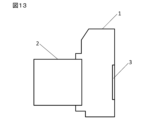
- FIG. 13 is a schematic diagram of a camera equipped with the variable magnification optical system of this embodiment.
- Camera 1 is a so-called mirrorless camera with interchangeable lenses that has the optical system according to the first embodiment described above as the photographic lens 2.
- camera 1 In camera 1, light from an object (subject) (not shown) is collected by photographing lens 2 and reaches image sensor 3. Image sensor 3 converts the light from the subject into image data. When the photographer presses a release button (not shown), the image data is stored in memory (not shown). In this way, the photographer can photograph the subject using camera 1.
- variable magnification optical system of the first embodiment mounted on the camera 1 as the photographic lens 2 is a variable magnification optical system with good optical performance. Therefore, the camera 1 can achieve good optical performance. Note that the same effects as the camera 1 can be achieved by constructing a camera that mounts the variable magnification optical system of the second to sixth embodiments as the photographic lens 2.
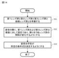
- FIG. 14 is a flow chart outlining the manufacturing method for the variable magnification optical system of this embodiment.
- the manufacturing method for the variable magnification optical system of this embodiment shown in FIG. 14 includes the following steps S11 to S13.
- Step S11 Prepare the first lens group, the second lens group, the third lens group, and the subsequent lens group.
- Step S12 When changing the magnification, the first lens group and the third lens group are fixed relative to the image plane, and the spacing between adjacent lens groups is changed.
- Step S13 The variable magnification optical system is made to satisfy the following conditional expression. (1) 0.24 ⁇ (TL/f1)/(ft/fw) ⁇ 0.55 however, TL: Distance from the lens surface closest to the object to the image surface f1: Focal length of the first lens group ft: Focal length of the variable magnification optical system in the telephoto end state fw: Focal length of the variable magnification optical system in the wide-angle end state
- the manufacturing method for the variable magnification optical system of this embodiment makes it possible to manufacture an optical system with good imaging performance.
Landscapes
- Physics & Mathematics (AREA)
- General Physics & Mathematics (AREA)
- Optics & Photonics (AREA)
- Nonlinear Science (AREA)
- Lenses (AREA)
Priority Applications (3)
| Application Number | Priority Date | Filing Date | Title |
|---|---|---|---|
| JP2024554434A JPWO2024095860A1 (https=) | 2022-11-04 | 2023-10-25 | |
| CN202380076416.9A CN120077311A (zh) | 2022-11-04 | 2023-10-25 | 变倍光学系统、光学设备及变倍光学系统的制造方法 |
| US19/194,828 US20250258363A1 (en) | 2022-11-04 | 2025-04-30 | Variable magnification optical system, optical device, and method for manufacturing variable magnification optical system |
Applications Claiming Priority (2)
| Application Number | Priority Date | Filing Date | Title |
|---|---|---|---|
| JP2022177062 | 2022-11-04 | ||
| JP2022-177062 | 2022-11-04 |
Related Child Applications (1)
| Application Number | Title | Priority Date | Filing Date |
|---|---|---|---|
| US19/194,828 Continuation US20250258363A1 (en) | 2022-11-04 | 2025-04-30 | Variable magnification optical system, optical device, and method for manufacturing variable magnification optical system |
Publications (1)
| Publication Number | Publication Date |
|---|---|
| WO2024095860A1 true WO2024095860A1 (ja) | 2024-05-10 |
Family
ID=90930395
Family Applications (1)
| Application Number | Title | Priority Date | Filing Date |
|---|---|---|---|
| PCT/JP2023/038491 Ceased WO2024095860A1 (ja) | 2022-11-04 | 2023-10-25 | 変倍光学系、光学機器および変倍光学系の製造方法 |
Country Status (4)
| Country | Link |
|---|---|
| US (1) | US20250258363A1 (https=) |
| JP (1) | JPWO2024095860A1 (https=) |
| CN (1) | CN120077311A (https=) |
| WO (1) | WO2024095860A1 (https=) |
Citations (2)
| Publication number | Priority date | Publication date | Assignee | Title |
|---|---|---|---|---|
| JP2020016808A (ja) * | 2018-07-27 | 2020-01-30 | キヤノン株式会社 | ズームレンズ及びそれを有する撮像装置 |
| JP2021096331A (ja) * | 2019-12-16 | 2021-06-24 | オリンパス株式会社 | ズーム光学系、撮像光学系及びそれを備えた撮像装置 |
-
2023
- 2023-10-25 JP JP2024554434A patent/JPWO2024095860A1/ja active Pending
- 2023-10-25 WO PCT/JP2023/038491 patent/WO2024095860A1/ja not_active Ceased
- 2023-10-25 CN CN202380076416.9A patent/CN120077311A/zh active Pending
-
2025
- 2025-04-30 US US19/194,828 patent/US20250258363A1/en active Pending
Patent Citations (2)
| Publication number | Priority date | Publication date | Assignee | Title |
|---|---|---|---|---|
| JP2020016808A (ja) * | 2018-07-27 | 2020-01-30 | キヤノン株式会社 | ズームレンズ及びそれを有する撮像装置 |
| JP2021096331A (ja) * | 2019-12-16 | 2021-06-24 | オリンパス株式会社 | ズーム光学系、撮像光学系及びそれを備えた撮像装置 |
Also Published As
| Publication number | Publication date |
|---|---|
| US20250258363A1 (en) | 2025-08-14 |
| CN120077311A (zh) | 2025-05-30 |
| JPWO2024095860A1 (https=) | 2024-05-10 |
Similar Documents
| Publication | Publication Date | Title |
|---|---|---|
| JP7601082B2 (ja) | ズームレンズおよび光学機器 | |
| CN105556368B (zh) | 变焦镜头、光学设备和用于制造变焦镜头的方法 | |
| CN102346294B (zh) | 变焦镜头系统、光学设备和用于制造变焦镜头系统的方法 | |
| JP6669281B2 (ja) | ズームレンズ、および光学機器 | |
| CN110573924A (zh) | 变倍光学系统、光学装置和制造变倍光学系统的方法 | |
| CN110520777A (zh) | 变倍光学系统、光学装置和制造变倍光学系统的方法 | |
| JP2020034946A (ja) | ズームレンズ、および光学機器 | |
| WO2020012638A1 (ja) | 変倍光学系、光学機器、および変倍光学系の製造方法 | |
| CN112136068B (zh) | 光学系统以及光学设备 | |
| CN108139571A (zh) | 变焦镜头、光学设备以及变焦镜头的制造方法 | |
| JP5407363B2 (ja) | 変倍光学系、撮像装置、変倍光学系の製造方法 | |
| JP7338709B2 (ja) | 変倍光学系、光学機器および変倍光学系の製造方法 | |
| CN110494786A (zh) | 变倍光学系统、光学装置和制造变倍光学系统的方法 | |
| CN107884917B (zh) | 变倍光学系统和光学装置 | |
| CN110546544A (zh) | 变倍光学系统、光学装置和制造变倍光学系统的方法 | |
| CN108604003A (zh) | 变焦镜头、光学设备以及变焦镜头的制造方法 | |
| JP2025062142A (ja) | 変倍光学系、光学機器および変倍光学系の製造方法 | |
| WO2024095858A1 (ja) | 変倍光学系、光学機器および変倍光学系の製造方法 | |
| CN104769477B (zh) | 可变放大率光学系统、光学装置以及可变放大率光学系统的生产方法 | |
| JP5407365B2 (ja) | 変倍光学系、撮像装置、変倍光学系の製造方法 | |
| JP2025137252A (ja) | 変倍光学系、光学機器、および変倍光学系の製造方法 | |
| WO2023190739A1 (ja) | 変倍光学系、光学機器および変倍光学系の製造方法 | |
| WO2020012639A1 (ja) | 変倍光学系、光学機器、および変倍光学系の製造方法 | |
| CN104755985B (zh) | 变倍光学系统和光学装置 | |
| CN104755983B (zh) | 变倍光学系统、光学装置和制造变倍光学系统的方法 |
Legal Events
| Date | Code | Title | Description |
|---|---|---|---|
| 121 | Ep: the epo has been informed by wipo that ep was designated in this application |
Ref document number: 23885617 Country of ref document: EP Kind code of ref document: A1 |
|
| WWE | Wipo information: entry into national phase |
Ref document number: 2024554434 Country of ref document: JP |
|
| WWE | Wipo information: entry into national phase |
Ref document number: 202380076416.9 Country of ref document: CN |
|
| WWP | Wipo information: published in national office |
Ref document number: 202380076416.9 Country of ref document: CN |
|
| NENP | Non-entry into the national phase |
Ref country code: DE |
|
| 122 | Ep: pct application non-entry in european phase |
Ref document number: 23885617 Country of ref document: EP Kind code of ref document: A1 |