WO2024095802A1 - 走行制御システム、作業車両および走行制御方法 - Google Patents
走行制御システム、作業車両および走行制御方法 Download PDFInfo
- Publication number
- WO2024095802A1 WO2024095802A1 PCT/JP2023/038115 JP2023038115W WO2024095802A1 WO 2024095802 A1 WO2024095802 A1 WO 2024095802A1 JP 2023038115 W JP2023038115 W JP 2023038115W WO 2024095802 A1 WO2024095802 A1 WO 2024095802A1
- Authority
- WO
- WIPO (PCT)
- Prior art keywords
- work vehicle
- coordinate system
- approximation line
- image
- vehicle
- Prior art date
- Legal status (The legal status is an assumption and is not a legal conclusion. Google has not performed a legal analysis and makes no representation as to the accuracy of the status listed.)
- Ceased
Links
Images











Classifications
-
- G—PHYSICS
- G06—COMPUTING OR CALCULATING; COUNTING
- G06V—IMAGE OR VIDEO RECOGNITION OR UNDERSTANDING
- G06V10/00—Arrangements for image or video recognition or understanding
- G06V10/70—Arrangements for image or video recognition or understanding using pattern recognition or machine learning
- G06V10/74—Image or video pattern matching; Proximity measures in feature spaces
- G06V10/75—Organisation of the matching processes, e.g. simultaneous or sequential comparisons of image or video features; Coarse-fine approaches, e.g. multi-scale approaches; using context analysis; Selection of dictionaries
- G06V10/751—Comparing pixel values or logical combinations thereof, or feature values having positional relevance, e.g. template matching
-
- A—HUMAN NECESSITIES
- A01—AGRICULTURE; FORESTRY; ANIMAL HUSBANDRY; HUNTING; TRAPPING; FISHING
- A01B—SOIL WORKING IN AGRICULTURE OR FORESTRY; PARTS, DETAILS, OR ACCESSORIES OF AGRICULTURAL MACHINES OR IMPLEMENTS, IN GENERAL
- A01B69/00—Steering of agricultural machines or implements; Guiding agricultural machines or implements on a desired track
-
- A—HUMAN NECESSITIES
- A01—AGRICULTURE; FORESTRY; ANIMAL HUSBANDRY; HUNTING; TRAPPING; FISHING
- A01B—SOIL WORKING IN AGRICULTURE OR FORESTRY; PARTS, DETAILS, OR ACCESSORIES OF AGRICULTURAL MACHINES OR IMPLEMENTS, IN GENERAL
- A01B69/00—Steering of agricultural machines or implements; Guiding agricultural machines or implements on a desired track
- A01B69/001—Steering by means of optical assistance, e.g. television cameras
-
- A—HUMAN NECESSITIES
- A01—AGRICULTURE; FORESTRY; ANIMAL HUSBANDRY; HUNTING; TRAPPING; FISHING
- A01B—SOIL WORKING IN AGRICULTURE OR FORESTRY; PARTS, DETAILS, OR ACCESSORIES OF AGRICULTURAL MACHINES OR IMPLEMENTS, IN GENERAL
- A01B69/00—Steering of agricultural machines or implements; Guiding agricultural machines or implements on a desired track
- A01B69/007—Steering or guiding of agricultural vehicles, e.g. steering of the tractor to keep the plough in the furrow
- A01B69/008—Steering or guiding of agricultural vehicles, e.g. steering of the tractor to keep the plough in the furrow automatic
-
- G—PHYSICS
- G05—CONTROLLING; REGULATING
- G05D—SYSTEMS FOR CONTROLLING OR REGULATING NON-ELECTRIC VARIABLES
- G05D1/00—Control of position, course, altitude or attitude of land, water, air or space vehicles, e.g. using automatic pilots
- G05D1/40—Control within particular dimensions
- G05D1/43—Control of position or course in two dimensions [2D]
-
- G—PHYSICS
- G06—COMPUTING OR CALCULATING; COUNTING
- G06V—IMAGE OR VIDEO RECOGNITION OR UNDERSTANDING
- G06V10/00—Arrangements for image or video recognition or understanding
- G06V10/20—Image preprocessing
- G06V10/25—Determination of region of interest [ROI] or a volume of interest [VOI]
-
- G—PHYSICS
- G06—COMPUTING OR CALCULATING; COUNTING
- G06V—IMAGE OR VIDEO RECOGNITION OR UNDERSTANDING
- G06V10/00—Arrangements for image or video recognition or understanding
- G06V10/40—Extraction of image or video features
- G06V10/44—Local feature extraction by analysis of parts of the pattern, e.g. by detecting edges, contours, loops, corners, strokes or intersections; Connectivity analysis, e.g. of connected components
-
- G—PHYSICS
- G06—COMPUTING OR CALCULATING; COUNTING
- G06V—IMAGE OR VIDEO RECOGNITION OR UNDERSTANDING
- G06V20/00—Scenes; Scene-specific elements
- G06V20/10—Terrestrial scenes
- G06V20/188—Vegetation
-
- G—PHYSICS
- G06—COMPUTING OR CALCULATING; COUNTING
- G06V—IMAGE OR VIDEO RECOGNITION OR UNDERSTANDING
- G06V20/00—Scenes; Scene-specific elements
- G06V20/50—Context or environment of the image
- G06V20/56—Context or environment of the image exterior to a vehicle by using sensors mounted on the vehicle
-
- G—PHYSICS
- G06—COMPUTING OR CALCULATING; COUNTING
- G06V—IMAGE OR VIDEO RECOGNITION OR UNDERSTANDING
- G06V20/00—Scenes; Scene-specific elements
- G06V20/50—Context or environment of the image
- G06V20/56—Context or environment of the image exterior to a vehicle by using sensors mounted on the vehicle
- G06V20/588—Recognition of the road, e.g. of lane markings; Recognition of the vehicle driving pattern in relation to the road
Definitions
- This disclosure relates to a driving control system, a work vehicle, and a driving control method.
- vision guidance systems are being developed that use imaging devices such as cameras to detect crop rows or ridges in a field and control the travel of a work vehicle along the detected crop rows or ridges.
- Patent Document 1 discloses a work machine that travels along rows of cultivated land where crops are planted in the ridges. Patent Document 1 describes how the original image, which is captured by an on-board camera from diagonally above the cultivated land, is binarized and then a planar projective transformed image is generated. The technology disclosed in Patent Document 1 rotates the planar projective transformed image to generate a number of rotated images with different orientations, and detects work paths between the ridges.
- a travel control system includes a processing device that acquires a first time series image including a first portion of a crop row or ridge in a field from a first imaging device attached to an agricultural work vehicle facing a first direction, acquires a second time series image including a second portion of the crop row or ridge from a second imaging device attached to the work vehicle facing a second direction different from the first direction, performs image processing on the first time series image and the second time series image to determine a travel path for the work vehicle, and a control device that controls the travel of the work vehicle based on the travel path, and the processing device determines a first approximation line of the first portion in a vehicle coordinate system fixed to the work vehicle based on the first time series image, determines a second approximation line of the second portion in the vehicle coordinate system based on the second time series image, and determines the travel path based on the first approximation line and the second approximation line.
- a work vehicle includes a first imaging device, a second imaging device, and the above-described driving control system.
- a travel control method is a travel control method for a work vehicle implemented in a computer, which causes a computer to execute the following: acquiring a first time series image including a first portion of a crop row or ridge in a field from a first imaging device attached to the agricultural work vehicle facing a first direction; acquiring a second time series image including a second portion of the crop row or ridge from a second imaging device attached to the work vehicle facing a second direction different from the first direction; determining a first approximation line of the first portion in a vehicle coordinate system fixed to the work vehicle based on the first time series image; determining a second approximation line of the second portion in the vehicle coordinate system based on the second time series image; and determining a travel route for the work vehicle based on the first approximation line and the second approximation line.
- a driving control system includes a processing device that acquires a first time series image including a first portion of a crop row or ridge in a field from a first imaging device attached to an agricultural work vehicle facing a first direction, acquires a second time series image including a second portion of the crop row or ridge from a second imaging device attached to the work vehicle facing a second direction different from the first direction, performs image processing on the first time series image and the second time series image to determine a driving path for the work vehicle, and a control device that controls the driving of the work vehicle based on the output from the processing device, the processing device determines a first approximation line of the first portion in a vehicle coordinate system fixed to the work vehicle based on the first time series image, and determines a second approximation line of the second portion in the vehicle coordinate system based on the second time series image, and the control device controls the driving of the work vehicle based on a first distance from a front reference point on the work vehicle to the first approximation line
- a work vehicle includes a first imaging device, a second imaging device, and the above-mentioned driving control system.
- a travel control method is a travel control method for a work vehicle implemented in a computer, which causes a computer to execute the following: acquiring a first time series image including a first portion of a crop row or ridge in a field from a first imaging device attached to the agricultural work vehicle facing a first direction; acquiring a second time series image including a second portion of the crop row or ridge from a second imaging device attached to the work vehicle facing a second direction different from the first direction; determining a first approximation line of the first portion in a vehicle coordinate system fixed to the work vehicle based on the first time series image; determining a second approximation line of the second portion in the vehicle coordinate system based on the second time series image; and controlling the travel of the work vehicle based on a first distance from a forward reference point on the work vehicle to the first approximation line and a second distance from a rear reference point on the work vehicle to the second approximation line in the vehicle coordinate system.
- the general or specific aspects of the present disclosure may be realized by an apparatus, a system, a method, an integrated circuit, a computer program, or a computer-readable non-transitory storage medium, or any combination thereof.
- the computer-readable storage medium may include a volatile storage medium or a non-volatile storage medium.
- the apparatus may be composed of multiple devices. When the apparatus is composed of two or more devices, the two or more devices may be arranged in one device, or may be arranged separately in two or more separate devices.
- FIG. 2 is a diagram illustrating a schematic diagram of two imaging devices attached to an agricultural machine photographing the ground.
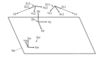
- FIG. 2 is a perspective view showing a schematic relationship between a body coordinate system and a camera coordinate system fixed with respect to an agricultural machine, and a world coordinate system fixed with respect to the ground.
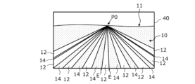
- FIG. 1 is a top view showing a schematic diagram of a part of a field having a plurality of rows of crops on the ground; 4 is a diagram showing a schematic example of a front image captured by a first imaging device of the agricultural machine shown in FIG. 3 .
- FIG. FIG. 2 is a top view illustrating a state in which the forward direction of the agricultural machine is inclined with respect to the direction in which the crop rows extend.
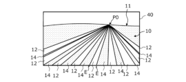
- FIG. 6 is a diagram showing a schematic example of an image of the front side captured by a first imaging device of the agricultural machine shown in FIG. 5 .
- FIG. 1 is a schematic top view of a portion of a field in which a plurality of curved rows of crops are provided on the ground; 1 is a block diagram showing an example configuration of a cruise control system according to an embodiment of the present disclosure.
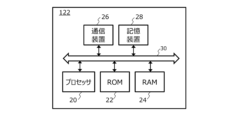
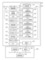
- FIG. 2 is a block diagram illustrating an example of a hardware configuration of a processing device.
- 13 is a flowchart showing an example of an algorithm used by the travel control system according to an embodiment of the present disclosure to determine a travel path for an agricultural machine based on the detection results of crop rows or furrows.
- 1 is an image corresponding to one frame of an image in a first time-series image captured by a first imaging device mounted on an agricultural machine.
- 4A to 4C are diagrams illustrating examples of images of the front that constitute a first time-series image captured by a first imaging device while an agricultural machine is traveling.
- 13A and 13B are diagrams showing schematic examples of rear images constituting second time-series images captured by a second imaging device while the agricultural machine is traveling.
- 1 is a perspective view showing a schematic arrangement relationship between a camera coordinate system of an imaging device in a first attitude and a camera coordinate system of an imaging device in a second attitude, and a reference plane Re; FIG.
- FIG. 11 is a top view diagram showing a schematic positional relationship between a first region of interest and a second region of interest included in a first top-view image and a second top-view image, respectively, in a vehicle coordinate system, and an agricultural machine.
- FIG. 11 is a flowchart showing an example of an algorithm according to a first implementation example.
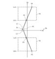
- 1 is a top view showing a schematic example of a first approximation line, a second approximation line, and an approximation curve on a vehicle coordinate system;
- FIG. 11 is a top view diagram showing a schematic positional relationship between a first region of interest and a second region of interest included in a first top-view image and a second top-view image, respectively, in a vehicle coordinate system, and an agricultural machine.
- FIG. 11 is a flowchart showing an example of an algorithm according to a first implementation example.
- 1 is a top view showing a schematic example of a first approximation line, a second approximation line,
- FIGS. 2A and 2B are schematic top views of a first portion and a second portion located in a first region of interest and a second region of interest, respectively, in a vehicle coordinate system when the agricultural machine is traveling through a straight crop row; 1 is a top view showing a schematic example of control points and an approximation curve on a vehicle coordinate system.
- FIG. FIG. 2 is a top view for explaining a travel control along a travel route set in a vehicle coordinate system.
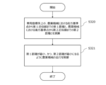
- 13 is a flowchart showing an example of an algorithm according to a second implementation example.
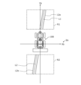
- FIG. 1 is a top view showing a schematic example of a positional relationship between a first approximation line, a second approximation line, a front reference point, and a rear reference point on a vehicle coordinate system, and an agricultural machine.
- FIG. 1 is a top view showing a schematic diagram of a first region of interest, a second region of interest, a first approximation line, and a second approximation line in a vehicle coordinate system when an agricultural machine is traveling through a straight crop row;
- FIG. FIG. 1 is a perspective view illustrating an example of the appearance of an agricultural machine according to an embodiment of the present disclosure.
- FIG. 1 is a side view showing a schematic diagram of an example of an agricultural machine with a work implement attached thereto.
- FIG. 1 is a block diagram showing an example of a schematic configuration of an agricultural machine and a work machine.
- agricultural machinery broadly includes machinery that performs basic agricultural tasks in fields, such as “plowing,” “planting,” and “harvesting.”
- Agricultural machinery is a machine that has the function and structure to perform agricultural tasks, such as plowing, sowing, pest control, fertilizing, planting crops, or harvesting, on the ground in a field. These agricultural tasks are sometimes referred to as “ground tasks” or simply “tasks.”
- Agricultural machinery does not need to have a running device for moving by itself, and may travel by being attached to or towed by another vehicle that has a running device.
- a work vehicle such as a tractor alone as an "agricultural machine” is not limited to cases where the work vehicle functions as a single "agricultural machine," and the work implement attached to or towed by the work vehicle and the entire work vehicle may function as a single “agricultural machine.”
- Examples of agricultural machinery include tractors, riding management machines, vegetable transplanters, grass cutters, and mobile field robots.
- the travel control system in an embodiment of the present disclosure includes a first and a second imaging device that are attached to an agricultural machine for use.
- Each of the first and second imaging devices is fixed to the agricultural machine so as to capture images of the ground on which the agricultural machine travels and acquire time-series images including at least a portion of the ground.
- the first imaging device is attached to the agricultural machine facing a first direction.
- the first imaging device acquires first time-series images including a first portion of the crop rows or ridges in the field.
- the second imaging device is attached to the agricultural machine facing a second direction different from the first direction.
- the second imaging device acquires second time-series images including a second portion of the crop rows or ridges in the field.
- the first and second portions of the crop rows or ridges will be described later.
- the first direction and the second direction are the directions in which the camera optical axes of the first and second imaging devices face, respectively.
- the first direction is the front of the agricultural machine
- the second direction is the rear of the agricultural machine. More specifically, as described below, the first direction is a direction that slopes from the forward direction of the agricultural machine toward the ground, and the second direction is a direction that slopes from the reverse direction opposite to the forward direction of the agricultural machine toward the ground.
- the first direction and the second direction are not limited to these directions.
- the first imaging device acquires an image of the front of the agricultural machine that constitutes the first time-series image.
- the second imaging device acquires an image of the rear of the agricultural machine that constitutes the second time-series image.
- a typical example of each of the first and second time-series images is a time-series color image, but they may also be monochrome images.
- FIG. 1 is a schematic diagram showing how a first imaging device 120 and a second imaging device 121 mounted on an agricultural machine 100, such as a tractor or a riding management machine, capture images of the ground 10.
- the agricultural machine 100 includes a vehicle body 110 capable of travelling.
- the first imaging device 120 is fixed to the front of the vehicle body 110
- the second imaging device 121 is fixed to the rear of the vehicle body 110.
- the mounting positions of the first and second imaging devices 120, 121 are not limited to this example.
- the first imaging device 120 may be fixed to the side of the vehicle body 110 with the camera optical axis facing in the forward direction of the agricultural machine 100.
- the second imaging device 121 may be fixed to the side of the vehicle body 110 with the camera optical axis facing in the reverse direction opposite to the forward direction or in a direction intersecting the forward direction.
- FIG. 1 shows a vehicle coordinate system ⁇ b having mutually orthogonal Xb, Yb, and Zb axes.
- the vehicle coordinate system ⁇ b is a coordinate system fixed to the agricultural machine 100.
- the origin of the vehicle coordinate system ⁇ b can be set, for example, on the rear wheel axle of the agricultural machine 100 in a top view from above the ground 10 on which the agricultural machine 100 runs, as described below.
- the figure shows the origin of the vehicle coordinate system ⁇ b as being located outside the agricultural machine 100.
- the Yb axis coincides with the forward direction (direction of arrow F) when the agricultural machine 100 moves straight ahead.
- the Xb axis coincides with the direction directly to the right when looking in the positive direction of the Yb axis from the coordinate origin, and the Zb axis coincides with the vertically upward direction.
- Each of the first and second imaging devices 120, 121 is, for example, an in-vehicle camera having a CCD (Charge Coupled Device) or CMOS (Complementary Metal Oxide Semiconductor) image sensor.
- Each of the first and second imaging devices 120, 121 in the embodiment of the present disclosure is, for example, a monocular camera capable of capturing video at a frame rate of 3 frames per second (fps) or more.
- FIG. 2 is a perspective view showing a schematic relationship between the vehicle coordinate system ⁇ b, the camera coordinate system ⁇ c1 of the first imaging device 120, the camera coordinate system ⁇ c2 of the second imaging device 121, and the world coordinate system ⁇ w fixed to the ground 10.
- the camera coordinate system ⁇ c1 has Xc1, Yc1, and Zc1 axes that are perpendicular to each other
- the camera coordinate system ⁇ c2 has Xc2, Yc2, and Zc2 axes that are perpendicular to each other.
- the world coordinate system ⁇ w has Xw, Yw, and Zw axes that are perpendicular to each other.
- the Xw and Yw axes of the world coordinate system ⁇ w are on a reference plane Re that extends along the ground 10.
- the first imaging device 120 is attached to the front of the vehicle body 110 so as to face the first direction (forward). Therefore, the position and orientation of the camera coordinate system ⁇ c1 relative to the vehicle coordinate system ⁇ b are fixed to a known state.
- the Zc1 axis of the camera coordinate system ⁇ c1 is on the camera optical axis ⁇ 1. In the illustrated example, the camera optical axis ⁇ 1 is inclined from the forward direction F of the agricultural machine 100 toward the ground 10, and the depression angle ⁇ 1 is greater than 0°.
- the second imaging device 121 is attached to the rear of the vehicle body 110 so as to face the second direction (rearward). Therefore, the position and orientation of the camera coordinate system ⁇ c2 relative to the vehicle coordinate system ⁇ b are fixed to a known state, similar to the camera coordinate system ⁇ c1.
- the Zc2 axis of the camera coordinate system ⁇ c2 is on the camera optical axis ⁇ 2. In the illustrated example, the camera optical axis ⁇ 2 is inclined toward the ground 10 from the reverse direction B opposite to the forward direction F of the agricultural machine 100, and the depression angle ⁇ 2 is greater than 0°.
- the forward direction F and reverse direction B of the agricultural machine 100 are roughly parallel to the ground 10 on which the agricultural machine 100 is traveling.
- Each of the depression angles ⁇ 1 and ⁇ 2 can be set, for example, in the range of 0° to 60°.
- the depression angles ⁇ 1 and ⁇ 2 may be the same or different.
- the depression angles ⁇ 1 and ⁇ 2 may be set to have negative values, in other words, positive elevation angles, respectively, and the orientations of the camera optical axes ⁇ 1 and ⁇ 2 may be set.
- the camera coordinate systems ⁇ c1 and ⁇ c2 together with the vehicle coordinate system ⁇ b, translate relative to the world coordinate system ⁇ w.
- the vehicle coordinate system ⁇ b and the camera coordinate systems ⁇ c1 and ⁇ c2 rotate relative to the world coordinate system ⁇ w.
- the agricultural machine 100 does not rotate in the pitch or roll directions, but moves approximately parallel to the ground 10.
- FIG. 3 is a top view showing a schematic diagram of a part of a field in which a plurality of crop rows 12 are provided on the ground 10.
- the crop rows 12 are rows formed by planting crops or seedlings continuously in one direction on the ground 10 of the field.
- the crop rows 12 may be a group of crops planted in the ridges of the field.
- a row formed by planting seedlings continuously in one direction on the ground 10 of the field may be called a "row of seedlings".
- each crop row 12 is a row formed by a group of crops planted in the field, the shape of the crop row is complex, strictly speaking, depending on the shape and arrangement of the crops.
- the width of the crop row 12 changes depending on the growth of the crop.
- each intermediate area 14 is an area sandwiched between two edge lines E facing each other between two adjacent crop rows 12.
- edge lines E facing each other between two adjacent crop rows 12.
- the intermediate area 14 functions as an area (work passage) through which the wheels of the agricultural machine 100 pass, so the “intermediate area” is sometimes referred to as the "work passage.”
- the "edge line" of a crop row refers to a reference line segment (which may include curves) for defining the travel path when an agricultural machine travels.
- the "travel path” may also be referred to as a "target path.”
- Such a reference line segment may be defined as both ends of a strip-shaped area (work passage) through which the wheels of the agricultural machine are permitted to pass.
- FIG. 3 shows a schematic diagram of an agricultural machine 100 traveling in a field in which rows of crops 12 are laid.
- This agricultural machine 100 has left and right front wheels 104F and left and right rear wheels 104R as a traveling device, and pulls a work machine (implement) 300.
- the front wheels 104F are steered wheels.
- thick dashed arrows L and R are drawn on the work passages 14 located on both sides of a single crop row 12 located in the center.
- the front wheels 104F and rear wheels 104R of the agricultural machine 100 are required to move along the arrows L and R in the work passage 14 so as not to step on the crop row 12.
- the first and second parts included in the crop row 12 are detected using the first and second imaging devices 120 and 121 attached to the agricultural machine 100, and the travel path is determined based on the approximation line of the first part and the approximation line of the second part in the vehicle coordinate system ⁇ b.
- FIG. 4 is a diagram showing a schematic example of a forward image 40 captured by the first imaging device 120 of the agricultural machine 100 shown in FIG. 3. Note that the explanation regarding the forward image 40 also applies to the rearward image captured by the second imaging device 121, as can be understood from FIG. 1 or FIG. 2.
- image 40 shown in FIG. 4 since the agricultural machine 100 is traveling on the travel path indicated by the solid arrow C as shown in FIG. 3, multiple crop rows 12 and intermediate areas (work paths) 14 extending parallel to each other on the ground 10 intersect at a vanishing point P0 on the horizon 11. The vanishing point P0 is located in the central area of the image 40.
- FIG. 5 is a top view diagrammatically illustrating a state in which the forward direction F of the agricultural machine 100 is inclined relative to the extension direction of the crop rows 12.
- FIG. 6 is a diagram diagrammatically illustrating an example of a forward image 40 captured by the first imaging device 120 of the agricultural machine 100 shown in FIG. 5.
- the vanishing point P0 is located in the right or left area of the image 40.
- the vanishing point P0 is located in the right area of the image 40.
- the travel control system in the embodiment of the present disclosure further includes a processing device and a control device.
- the processing device detects crop rows or ridges contained in the front and rear images captured by the first and second imaging devices 120, 121 attached to the agricultural machine 100, and linearly approximates the detected crop rows or ridges on the vehicle coordinate system to obtain an approximation line.
- the processing device further determines a travel route based on the two approximation lines obtained from the front and rear images.
- the control device controls the travel of the agricultural machine 100 based on the travel route.
- FIG. 3 shows a schematic diagram of the state in which the agricultural machine 100 is steered to reduce the position deviation and azimuth deviation from the travel path (arrow C), and the position and orientation (yaw angle) of the agricultural machine 100 in the state shown in FIG. 5 are adjusted.
- the left and right wheels of the agricultural machine 100 in the state shown in FIG. 3 are positioned on the lines indicated by arrows L and R in the work path 14, respectively.
- the automatic steering device in the agricultural machine 100 controls the steering angle of the steering wheels so that the front wheels 104F and rear wheels 104R do not deviate from the work path 14.
- FIG. 7 is a top view showing a schematic diagram of a part of a field in which a plurality of curved crop rows 12 are provided on the ground 10.
- the method of determining a travel path described below makes it possible to accurately detect the position of the crop rows or ridges from the front and rear images captured by the two imaging devices, even in a field in which curved crop rows or ridges are formed, and to precisely control the steering and travel of the agricultural machine 100 along the crop rows or ridges. In other words, a travel path along which the agricultural machine 100 should proceed can be appropriately generated.
- FIG. 8 is a block diagram showing an example of the configuration of a driving control system 1000 according to an embodiment of the present disclosure.
- the driving control system 1000 includes first and second imaging devices 120 and 121, a processing device 122, and a control device 124.
- the processing device 122 performs image processing of the first time-series image acquired by the first imaging device 120 and the second time-series image acquired by the second imaging device 121 to determine a driving route for the agricultural machine 100.
- the control device 124 is configured to control the driving of the agricultural machine 100 based on the driving route, or to control the driving of the agricultural machine 100 based on an output from the processing device 122.
- the control device 124 can be realized by an electronic control unit (ECU) for automatic steering control, which will be described later, and is included in, for example, an automatic driving device that controls the driving of the agricultural machine 100.
- the ECU is an on-board computer.
- the processing device 122 may be realized by an ECU for image recognition.
- the processing device 122 is connected to the first and second imaging devices 120, 121 by a serial signal line such as a wire harness so as to receive image data output by the first and second imaging devices 120, 121.
- a part of the image recognition process performed by the processing device 122 may be performed inside each of the first and second imaging devices 120, 121 (inside the camera module).
- FIG. 9 is a block diagram showing an example of the hardware configuration of the processing device 122.
- the processing device 122 includes a processor 20, a ROM (Read Only Memory) 22, a RAM (Random Access Memory) 24, a communication device 26, and a storage device 28. These components are interconnected via a bus 30.
- the processor 20 is a semiconductor integrated circuit, and is also referred to as a central processing unit (CPU) or a microprocessor.
- the processor 20 may include a graphics processing unit (GPU).
- the processor 20 sequentially executes a computer program that describes a predetermined set of instructions stored in the ROM 22, and realizes the processing required for the crop row or ridge detection and travel path generation of the present disclosure.
- Part or all of the processor 20 may be an FPGA (Field Programmable Gate Array) equipped with a CPU, an ASIC (Application Specific Integrated Circuit), or an ASSP (Application Specific Standard Product).
- the communication device 26 is an interface for data communication between the processing device 122 and an external computer.
- the communication device 26 can perform wired communication using a controller area network (CAN) or the like, or wireless communication conforming to the Bluetooth (registered trademark) standard and/or the Wi-Fi (registered trademark) standard.
- CAN controller area network
- Wi-Fi registered trademark
- the storage device 28 can store images acquired from the first and second imaging devices 120, 121, or image data in the middle of processing.
- Examples of the storage device 28 include a hard disk drive or a non-volatile semiconductor memory.
- the hardware configuration of the processing device 122 is not limited to the above example. It is not necessary for part or all of the processing device 122 to be mounted on the agricultural machine 100. By utilizing the communication device 26, it is also possible to cause one or more computers located outside the agricultural machine 100 to function as part or all of the processing device 122. For example, a server computer connected to a network can function as part or all of the processing device 122. On the other hand, a computer mounted on the agricultural machine 100 may execute all of the functions required of the processing device 122.
- FIG. 10 is a flowchart showing an example of an algorithm by which the travel control system in an embodiment of the present disclosure determines the travel path of the agricultural machine based on the results of crop row or ridge detection.
- the processing device 122 is configured to execute the following operations S100, S200, and S300.
- a first time series image including a first portion of the crop rows or ridges in the field is acquired from the first imaging device 120, and a second time series image including a second portion of the crop rows or ridges in the field is acquired from the second imaging device 121.
- a first approximation line of the first portion in the vehicle coordinate system ⁇ b is obtained based on the first time-series image
- a second approximation line of the second portion in the vehicle coordinate system ⁇ b is obtained based on the second time-series image.
- the first time-series image is a collection of images captured by the first imaging device 120 in a time-series manner. Each image is composed of a group of pixels in units of frames.
- the second time-series image is similar to the first time-series image. For example, if the first imaging device 120 outputs images at a frame rate of 30 frames/second, the processing device 122 can acquire new images at intervals of approximately 33 milliseconds. The same is true for the second imaging device 121.
- the speed at which an agricultural machine 100 such as a tractor travels in a field is relatively low compared to the speed of an ordinary automobile traveling on a public road, and may be, for example, approximately 10 kilometers per hour or less.
- the processing device 122 may acquire images at intervals of, for example, approximately 100 to 300 milliseconds, and it is not necessary to process all of the frames of images captured by the first imaging device 120 and the second imaging device 121.
- the processing device 122 may automatically change the acquisition period of the images to be processed by the processing device 122 depending on the traveling speed of the agricultural machine 100.
- FIG. 11 shows an example of one frame of image 40 in the first time-series image captured by the first imaging device 120 (a monocular camera in this example) mounted on the agricultural machine 100.
- the image in FIG. 11 shows rows of crops planted in rows on the ground in a farm field.
- the rows of crops are arranged approximately parallel and at equal intervals on the ground, and the camera optical axis ⁇ 1 of the first imaging device 120 is inclined from the forward direction F of the agricultural machine toward the ground (see FIGS. 1 and 3).
- the camera optical axis ⁇ 1 does not need to be parallel to the forward direction F of the agricultural machine 100 as described above, and may be incident on the ground ahead of the forward direction F of the agricultural machine 100.
- the second imaging device 121 also captures an image similar to image 40, showing rows of crops planted in rows on the ground in the field, arranged approximately parallel and at equal intervals.
- the camera optical axis ⁇ 2 of the second imaging device 121 is inclined from the reverse direction B of the agricultural machine towards the ground (see Figures 1 and 3). In other words, like the camera optical axis ⁇ 1, the camera optical axis ⁇ 2 does not need to be parallel to the reverse direction B, and may be incident on the ground ahead of the reverse direction B.
- FIG. 12A shows an example of a forward image 40 constituting a first time series image captured by the first imaging device 120 while the agricultural machine 100 is traveling.
- FIG. 12B shows an example of a rearward image 41 constituting a second time series image captured by the second imaging device 121 while the agricultural machine 100 is traveling.
- the crop row 12 is shown as a straight line in FIGS. 12A and 12B, but the crop row 12 in the actual captured image includes curved portions.
- the processing device 122 acquires a first time series image including a first portion of the crop rows 12 in the field from the first imaging device 120, and acquires a second time series image including a second portion of the crop rows or ridges from the second imaging device 121.
- the first and second portions of the crop rows 12 in the field are each part of the crop rows that are the subject of crop row detection required for row following travel control.
- the first portion 12a of the crop rows 12 in the field is a portion located at the center of the multiple crop rows 12 included in the front image 40 illustrated in FIG. 12A
- the second portion 12b is a portion located at the center of the multiple crop rows 12 included in the rear image 41 illustrated in FIG. 12B.
- the processing device 122 obtains a first approximation line of the first portion 12a in the vehicle coordinate system ⁇ b based on the first time series image, and obtains a second approximation line of the second portion 12b in the vehicle coordinate system ⁇ b based on the second time series image.
- an example of a method for converting the first time series image into the first top view image will be described using the first imaging device 120 as an example. Using this method, it is also possible to convert the second time series image acquired by the second imaging device 121 into the second top view image.
- the top view image is an image viewed from above the ground on which the agricultural machine 100 runs, and may be referred to as a "bird's-eye view image.”
- the top view image is associated with the vehicle coordinate system ⁇ b.
- FIG. 13 is a perspective view showing a schematic arrangement relationship between the camera coordinate system ⁇ c1 of the imaging device in the first posture (position and orientation: pose) and the camera coordinate system ⁇ c3 of the imaging device in the second posture, and the reference plane Re.
- FIG. 13 also shows the vehicle coordinate system ⁇ b.
- the camera coordinate system ⁇ c1 is inclined so that its Zc axis intersects the reference plane Re at an angle.
- the imaging device in the first posture corresponds to the first imaging device 120 attached to the agricultural machine 100.
- the camera coordinate system ⁇ c3 has its Zc axis perpendicular to the reference plane Re.
- the plane including the Xb and Yb axes of the vehicle coordinate system ⁇ b (hereinafter referred to as the "vehicle coordinate system plane") is parallel to the reference plane Re.
- the Zc axis of the camera coordinate system ⁇ c3 is also perpendicular to the vehicle coordinate system plane.
- the camera coordinate system ⁇ c3 is positioned so that an overhead image viewed from directly above in the normal direction of the reference plane Re or the vehicle coordinate system plane can be acquired.
- a virtual image plane Im1 exists at a position away from the origin O1 of the camera coordinate system ⁇ c1 in the Zc-axis direction by the camera's focal length.
- the image plane Im1 is orthogonal to the Zc axis and the camera optical axis ⁇ 1.
- the pixel positions on the image plane Im1 are defined by an image coordinate system having mutually orthogonal u- and v-axes.
- the coordinates of points P1 and P2 located on the reference plane Re are (X1, Y1, Z1) and (X2, Y2, Z2) in the world coordinate system ⁇ w, respectively.
- the reference plane Re is set to extend along the ground.
- Points P1 and P2 on the reference plane Re are transformed into points p1 and p2 on the image plane Im1 of the imaging device in the first attitude by perspective projection of the pinhole camera model.
- points p1 and p2 are located at pixel positions indicated by the coordinates (u1, v1) and (u2, v2), respectively.
- a virtual image plane Im2 exists at a position away from the origin O3 of the camera coordinate system ⁇ c3 by the focal length of the camera in the Zc-axis direction.
- the image plane Im2 is parallel to the reference plane Re and is located on the vehicle coordinate system plane.
- the pixel positions on the image plane Im2 are defined by the vehicle coordinate system ⁇ b.
- the unit of the vehicle coordinate system ⁇ b is, for example, meters.
- the points P1 and P2 on the reference plane Re are transformed into points p1 * and p2 * on the image plane Im2 by perspective projection, respectively.
- the points p1 * and p2 * are located at pixel positions indicated by the coordinates (u1 * , v1 * ) and (u2 * , v2 * ) on the vehicle coordinate system ⁇ b, respectively.
- a corresponding point (u * , v * ) on the image plane Im2 can be obtained from an arbitrary point (u, v) on the image plane Im1 by homography transformation.
- homography transformation is defined by a 3-row x 3-column transformation matrix H.
- the contents of the transformation matrix H are defined by the values of h 11 , h 12 , . . . , h 32 as shown below.
- the eight numerical values (h 11 , h 12 , . . . , h 32 ) can be calculated using a known algorithm by capturing an image of a calibration board placed on the reference plane Re using an imaging device attached to the agricultural machine 100.
- the contents of the transformation matrices H1 and H2 depend on the reference plane Re, so when the position of the reference plane Re changes, the contents of the transformation matrix H also change.
- a top view image of the ground can be generated from an image of the ground captured by an imaging device in a first orientation (an imaging device attached to an agricultural machine).
- homography transformation makes it possible to convert the coordinates of any point on the image plane Im1 of the imaging device into the coordinates of a point on the image plane Im2 of a virtual imaging device in a specified orientation with respect to the reference plane Re.
- the processing device 122 executes a software program based on the above algorithm to generate an overhead image of the ground 10 from the time-series images output from the imaging device. Before the process of generating the overhead image, pre-processing such as white balance and noise reduction may be applied to the time-series images.
- the ground 10 may have irregularities such as ridges, furrows, and grooves. In such cases, the reference plane Re may be displaced upward from the bottom of such irregularities. The distance of the displacement may be set appropriately according to the unevenness of the ground 10 on which the crop is cultivated.
- the agricultural machine 100 when traveling on the ground 10, if the vehicle body 110 (see FIG. 1) rolls or pitches, the attitude of the imaging device 120 changes, and the contents of the transformation matrix H1 may change.
- the roll and pitch rotation angles of the vehicle body 110 are measured by an inertial measurement unit (IMU), the transformation matrix H1 and the transformation matrix H can be corrected according to the change in attitude of the imaging device.
- IMU inertial measurement unit
- the processing device 122 can convert the second time-series image acquired by the second imaging device 121 into a second top-view image in a manner similar to the conversion from the first time-series image acquired by the first imaging device 120 into a first top-view image.
- the processing device 122 converts the first time series image and the second time series image into a first top view image and a second top view image on the vehicle coordinate system ⁇ b, respectively. In other words, the processing device 122 generates a first top view image and a second top view image on the vehicle coordinate system ⁇ b from the first time series image and the second time series image, respectively.
- the processing device 122 determines a first approximation line and a second approximation line from the first top view image and the second top view image, respectively, on the vehicle coordinate system ⁇ b.
- FIG. 14 is a top view that shows a schematic diagram of the positional relationship between the agricultural machine 100 and the first and second regions of interest R1 and R2 included in the first and second top view images, respectively, in the vehicle coordinate system ⁇ b.
- the first and second top view images are associated with the vehicle coordinate system ⁇ b.
- the first top view image includes the first region of interest R1
- the second top view image includes the second region of interest R2.
- the regions of interest are regions that are subject to image processing (or image recognition processing) by the processing device 122.
- the first and second regions of interest R1 and R2 are each shown as a rectangular region with a dashed line.
- the first region of interest R1 is located in front of the agricultural machine 100, and the second region of interest R2 is located behind the agricultural machine 100.
- the first region of interest R1 does not overlap the second region of interest R2 on the vehicle coordinate system ⁇ b.
- the first top view image and the second top view image may partially overlap on the vehicle coordinate system ⁇ b.
- the distance df between the straight line Lb1 defining the lower end of the first region of interest R1 and the front end of the agricultural machine 100, and/or the distance dr between the straight line Lu2 defining the upper end of the second region of interest R2 and the rear end of the agricultural machine 100 may each be set in the range of, for example, 1 m to 2 m.
- the rear end of the agricultural machine 100 is located at the outer edge of the working implement.
- the length in the Xb axis direction of each of the first region of interest R1 and the second region of interest R2 may be set in the range of, for example, 3 m to 5 m, and the length in the Yb axis direction may be set in the range of, for example, 3 m to 5 m. From the viewpoint of generating a local driving route, it is preferable to set a narrow region of interest.
- the processing device 122 may adaptively change the size (or range) of at least one of the first region of interest R1 and the second region of interest R2 according to the traveling speed of the agricultural machine 100.
- the processing device 122 may also adaptively change at least one of the distances df and dr described above according to the traveling speed of the agricultural machine 100.
- the processing device 122 may set the first region of interest R1 and the second region of interest R2 on the vehicle coordinate system ⁇ b so that the distances df and dr are smaller and the ranges of the first region of interest R1 and the second region of interest R2 are narrower, as the traveling speed of the agricultural machine 100 is higher.
- the local traveling path is useful for row-following traveling control along curved crop rows or ridges.
- a region R1a in the forward image 40 which corresponds to the first region of interest R1 shown in FIG. 14, is shown by a dashed rectangular region.
- a region R2a in the rear image 41 which corresponds to the second region of interest R2 shown in FIG. 14, is shown by a dashed rectangular region.
- the first portion 12a of the crop row located within the first region of interest R1 shown in FIG. 14 corresponds to the first portion 12a of the crop row located within the region R1a included in the forward image 40 shown in FIG. 12A.
- the second portion 12b of the crop row located within the second region of interest R2 shown in FIG. 14 corresponds to the second portion 12b of the crop row located within the region R2a shown in FIG. 12B.
- the processing device 122 determines a first approximation line L1 from the first portion 12a located in the first region of interest R1, and determines a second approximation line L2 from the second portion 12b located in the second region of interest R2.
- the processing device 122 determines the approximation lines using, for example, the least squares method.
- the first approximation line L1 linearly approximates the first portion 12a located in the first region of interest R1, and corresponds to, for example, a line passing through the center of the edge lines at both ends of the first portion 12a.
- the second approximation line L2 linearly approximates the second portion 12b located in the second region of interest R2, and corresponds to, for example, a line passing through the center of the edge lines at both ends of the second portion 12b.
- the processing device 122 generates an enhanced image in which the color of the crop row to be detected is enhanced from a time-series image (time-series color image), which is a color image.
- This enhanced image is obtained, for example, by converting the RGB values of one frame of the time-series image into an excess green index (ExG).
- the processing device 122 generates a graph from the enhanced image, plotting the relationship between ExG and the number of pixels in the image.
- the processing device 122 From this graph, the processing device 122 generates a top-view image seen from above the ground, in which the crop row color index value is classified into first pixels that are equal to or greater than a threshold value and second pixels that are less than the threshold value, and determines the position of the edge line of the crop row based on the index value of the first pixel.
- the processing device 122 obtains an approximation line that linearly approximates the crop row based on the position of the edge line of the crop row.
- the processing device 122 obtains a first amount of movement within an image plane for each of a plurality of feature points from a plurality of images acquired at different times in a time-series image by feature point matching.
- the processing device 122 further perspectively projects each of the plurality of feature points from the image plane onto a reference plane corresponding to the ground, and obtains a second amount of movement for each projected point within the reference plane based on the first amount of movement.
- the processing device 122 estimates the heights of the plurality of feature points from the reference plane based on the second amount of movement to detect the edge lines of the ridges on the ground.
- the processing device 122 obtains an approximation line that linearly approximates the ridges based on the positions of the edge lines of the ridges.
- the method of detecting crop rows or ridges formed in a field is not limited to the examples described above, and can be performed using a wide variety of known algorithms.
- a method of approximating crop rows to a linear shape is described in detail in Japanese Patent Publication No. 2624390, the patent owner of which is the present applicant.
- the entire disclosure of Japanese Patent Publication No. 2624390 is incorporated herein by reference.
- a method of detecting lines formed by ridge steps or furrows is described in Japanese Patent Publication No. 2016-146061.
- the entire disclosure of Japanese Patent Publication No. 2016-146061 is incorporated herein by reference.
- the time series image is converted into a top view image (or an overhead image), and then an approximation line of the crop row in the vehicle coordinate system is obtained from the top view image, but the present disclosure is not limited to this.
- the processing device 122 may obtain a first pre-approximation line that linearly approximates a first portion of the crop row in a first image coordinate system that defines the coordinates of the pixels of the first time series image, and a second pre-approximation line that linearly approximates a second portion of the crop row in a second image coordinate system that defines the coordinates of the pixels of the second time series image.
- the processing device 122 may coordinate-transform the first pre-approximation line from the first image coordinate system to the vehicle coordinate system to obtain the first approximation line in the vehicle coordinate system, and coordinate-transform the second pre-approximation line from the second image coordinate system to the vehicle coordinate system to obtain the second approximation line in the vehicle coordinate system.
- the target of coordinate transformation is an approximate line rather than the entire image, which can reduce the computational load on the processing unit 122.
- the processing device 122 determines the travel route of the agricultural machine 100 based on the first approximation line L1 and the second approximation line L2.
- a first and second implementation example will be described as specific examples of processing of operation S300.
- the processing device 122 finds an approximation curve from a plurality of points on the first approximation line and the second approximation line, and determines a driving route based on the approximation curve.
- An example of the approximation curve is a Bezier curve.
- FIG. 15 is a flowchart showing an example of an algorithm according to the first implementation example.
- FIG. 16 is a top view that shows a schematic example of the first approximation line L1, the second approximation line L2, and the approximation curve AC on the vehicle coordinate system ⁇ b.
- the processing device 122 determines a plurality of points including a first intersection P1 between the first approximation line L1 and the second approximation line L2 on the vehicle coordinate system ⁇ b based on the first approximation line L1, the second approximation line L2, the first region of interest R1, and the second region of interest R2.
- the processing device 122 determines an approximation curve AC from the plurality of points.
- the plurality of points includes the second and third intersections P2 and P3 in addition to the first intersection P1.
- the second intersection P2 is the intersection of a straight line Lb1 that defines the lower end of the first region of interest R1 in the vehicle coordinate system ⁇ b and the first approximation line L1.
- the third intersection P3 is the intersection of a straight line Lu2 that defines the upper end of the second region of interest R2 in the vehicle coordinate system ⁇ b and the second approximation line L2.
- the processing device 122 is capable of finding an approximation curve based on the first, second, and third intersection points P1 to P3. However, in the first implementation example, in order to improve the accuracy of the calculation of the approximation curve, the processing device 122 finds further points on the first approximation line and the second approximation line.
- the processing device 122 further determines a fourth intersection P4 and a fifth intersection P5.
- the multiple points in the first implementation example further include a fourth and fifth intersection P4, P5 in addition to the first, second and third intersections P1 to P3.
- the fourth intersection P4 is the intersection of a straight line Lu1 that defines the upper end of the first region of interest R1 in the vehicle coordinate system ⁇ b and the first approximation line L1.
- the fifth intersection P5 is the intersection of a straight line Lb2 that defines the lower end of the second region of interest R2 and the second approximation line L2.
- Each of the first, second, third, fourth and fifth intersections P1 to P5 is located at a pixel position represented by coordinates in the vehicle coordinate system ⁇ b.
- the processing device 122 obtains an approximation curve from the first, second, third, fourth and fifth intersection points P1 to P5.
- the processing device 122 obtains a Bezier curve having both ends at the fourth intersection point P4 and the fifth intersection point P5.
- the processing device 122 obtains a Bezier curve from the following formula 6.
- P(t) represents the formula of the curve
- B represents the control point
- t represents the parameter.
- the formula 7 shows the Bernstein basis function.
- the first, second, third, fourth and fifth intersection points P1 to P5 are control points.
- FIG. 16 shows an example of a Bezier curve obtained from these control points.
- the approximation curve of the present disclosure is not limited to a Bezier curve, and may be a curve such as a spline curve.
- FIG. 17 is a top view showing a schematic diagram of the first portion 12a and the second portion 12b located in the first region of interest R1 and the second region of interest R2 in the vehicle coordinate system ⁇ b when the agricultural machine 100 is traveling along a straight crop row.
- FIG. 18 is a top view showing a schematic diagram of an example of control points and approximation curves on the vehicle coordinate system ⁇ b. Even when the agricultural machine 100 travels along a straight crop row as shown in FIG. 5, the travel path can be determined by the first implementation example.
- the processing device 122 determines a first approximation line L1 that linearly approximates the first portion 12a of the straight crop row, and a second approximation line L2 that linearly approximates the second portion 12b of the straight crop row.
- the processing device 122 determines the first, second, third, fourth, and fifth intersection points P1 to P5, which are control points, on the vehicle coordinate system ⁇ b, based on the first approximation line L1, the second approximation line L2, the first region of interest R1, and the second region of interest R2.
- the first, second, third, fourth, and fifth intersection points P1 to P5 are arranged in a substantially straight line. For this reason, the shape of the approximation curve AC approaches a straight line as closely as possible.
- the processing device 122 is able to determine the approximation curve AC from the first, second, third, fourth, and fifth intersection points P1 to P5.
- the processing device 122 determines the approximate curve AC found on the vehicle coordinate system ⁇ b as the driving route.
- the processing device 122 generates the driving route while finding the approximate curve at intervals of, for example, 200 ms.
- the control device 124 controls the travel of the agricultural machine 100 based on the travel route determined by the processing device 122. In other words, the control device 124 controls the travel of the agricultural machine 100 based on the travel route set in the vehicle coordinate system ⁇ b.
- FIG. 19 is a top view for explaining the file tracing travel control along a travel path set in the vehicle coordinate system ⁇ b.
- the approximation curve AC (i.e., the travel path) in the vehicle coordinate system ⁇ b includes a first curved portion AC1 located on the first region of interest R1 side and a second curved portion AC2 located on the second region of interest R2 side with respect to the first intersection point P1.
- the origin Ob of the vehicle coordinate system ⁇ b in the embodiment of the present disclosure is located on the rear wheel axle of the agricultural machine 100 in a top view seen from above the ground on which the agricultural machine 100 travels.
- the origin Ob of the vehicle coordinate system ⁇ b located on the rear wheel axle may be referred to as the "rear reference point Rb.”
- the control device 124 controls the travel of the agricultural machine 100 based on the deviation between the origin Ob (or rear reference point Rb) of the vehicle coordinate system ⁇ b and the second curved portion AC2. In other words, the control device 124 controls the position of the agricultural machine 100 so that the origin Ob of the vehicle coordinate system ⁇ b approaches the second curved portion AC2. Specifically, the control device 124 controls the position of the agricultural machine 100 so that the distance from the origin Ob of the vehicle coordinate system ⁇ b to the tangent at a certain point among the points on the second curved portion AC2, i.e., the length of the perpendicular line, is minimized.
- the control device 124 can control the travel of the agricultural machine 100 based further on the azimuth deviation between the direction of the tangent to a certain point in the group of points on the first curved portion AC1 and the orientation of the agricultural machine 100. For example, the control device 124 controls the attitude of the agricultural machine 100 so that the angle ⁇ formed by the tangent to the first curved portion AC1 at the intersection P6 where the first curved portion AC1 intersects with the Yb axis of the vehicle coordinate system ⁇ b and the arrow F indicating the forward direction of the agricultural machine 100 is minimized.
- crop rows or ridges were detected by processing forward images captured by an imaging device that captures the forward view, the position of the crop rows or ridges was estimated based on the detection results of the crop rows or ridges, and the travel route was determined based on the estimation results.
- this method when the crop rows or ridges have curved portions, it was difficult to precisely control the steering and travel of the agricultural machine 100 along the curved crop rows or ridges. Also, in the case of curved crop rows or ridges, it was difficult to apply automatic steering technology that uses a positioning system such as GNSS.
- the accuracy of estimating the position of the crop row to be traced can be improved by processing the front and rear images acquired by two imaging devices that capture the front and rear.
- precise control of steering and traveling of the agricultural machine 100 along the crop rows or ridges becomes possible.
- This type of row tracing travel control makes precise automatic steering possible in environments where automatic steering technology using positioning systems such as GNSS is difficult to apply.
- the processing device 122 in the second implementation example does not generate an approximation curve from the first and second approximation lines. Instead, the control device 124 directly controls the travel of the agricultural machine 100 based on the first and second approximation lines determined by the processing device 122. For this reason, in the second implementation example, the first and second approximation lines are referred to as a travel path. In this manner, the "travel path" in the present disclosure broadly includes the first and second approximation lines themselves.
- the control device 124 in the second implementation example controls the travel of the agricultural machine 100 based on a first distance from a forward reference point on the agricultural machine 100 to a first approximation line and a second distance from a rear reference point on the agricultural machine 100 to a second approximation line on the vehicle coordinate system ⁇ b.
- FIG. 20 is a flowchart showing an example of an algorithm according to the second implementation example.
- FIG. 21 is a top view that shows a schematic example of the positional relationship between the agricultural machine 100 and the first approximation line L1, the second approximation line L2, the front reference point Rf, and the rear reference point Rb on the vehicle coordinate system ⁇ b.
- the control device 124 alone, or the control device 124 in cooperation with the processing device 122, determines a first distance d1 from the forward reference point Rf of the agricultural machine 100 to the first approximation line L1, and a second distance d2 from the rear reference point Rb of the agricultural machine 100 to the second approximation line L2, on the vehicle coordinate system ⁇ b.
- the distance from the reference point to the approximation line corresponds to the length of the perpendicular line from the reference point to the approximation line.
- the front reference point Rf is located on the front wheel axle of the agricultural machine 100
- the rear reference point Rb is located on the rear wheel axle of the agricultural machine 100.
- the positions of the front reference point Rf and the rear reference point Rb are not limited to this.
- the control device 124 controls the travel of the agricultural machine 100 so that the first distance d1 is minimized and the second distance d2 is minimized.
- each of the first distance d1 and the second distance d2 is expressed as a signed distance that specifies the distance from a point to a line.
- the control device 124 estimates the azimuth deviation between the first approximation line L1 and the orientation of the agricultural machine 100 from the signed first distance d1, and further estimates the position deviation between the rear reference point Rb and the second approximation line L2 from the signed second distance d2.
- the control device 124 estimates the orientation deviation of the agricultural machine 100 from the magnitude and sign of the first distance d1.
- the orientation deviation is given, for example, by the angle ⁇ between the forward direction of the agricultural machine 100 (the direction of the arrow F) and the first approximation line L1.
- the direction of the arrow F coincides with the direction of the Yb axis in the vehicle coordinate system ⁇ b.
- the angle ⁇ is, for example, an angle in which the clockwise direction is positive.
- the control device 124 also estimates the position deviation between the rear reference point Rb and the second approximation line L2 from the magnitude and sign of the second distance d2.
- control device 124 can estimate the deviation between the position of the agricultural machine 100 and the second approximation line L2 from the magnitude and sign of the second distance d2. By using the signed distance, the orientation deviation and position deviation of the agricultural machine 100 with respect to the travel route can be estimated with relatively high accuracy. In this way, the control device 124 controls the travel of the agricultural machine 100 so that the orientation deviation and position deviation are each small.
- FIG. 22 is a top view that shows a schematic of the first region of interest R1, the second region of interest R2, the first approximation line L1, and the second approximation line L2 in the vehicle coordinate system ⁇ b when the agricultural machine 100 is traveling along a straight crop row. Even when the agricultural machine 100 travels along a straight crop row as shown in FIG. 5, it is possible to control the travel of the agricultural machine 100 by using the second implementation example.
- the processing device 122 determines the first approximation line L1 that linearly approximates the straight first portion of the crop row, and the second approximation line L2 that linearly approximates the straight second portion of the crop row.
- the control device 124 controls the travel of the agricultural machine 100 so that the first distance d1 is minimized and the second distance d2 is minimized. As described above, the control device 124 estimates the orientation deviation of the agricultural machine 100 from the magnitude and sign of the first distance d1, and estimates the position deviation between the rear reference point Rb and the second approximation line L2 from the magnitude and sign of the second distance d2. In this way, the agricultural machine 100 is able to travel along a straight crop row.
- the accuracy of estimating the position of the crop row to be traced can be improved by processing the front and rear images acquired by two imaging devices that capture the front and rear.
- precise control of steering and running of the agricultural machine 100 along the crop rows or ridges becomes possible.
- agricultural machines have been developed that are equipped with a function for running the agricultural machine in a straight line parallel to a reference line connecting a start point and an end point.
- the algorithm according to the second implementation example can be easily implemented in such functions and is useful.
- Fig. 23 is a perspective view showing an example of the appearance of the agricultural machine 100 according to an embodiment of the present disclosure.
- Fig. 24 is a side view showing a schematic example of the agricultural machine 100 with the work implement 300 attached.
- the agricultural machine 100 according to an embodiment of the present disclosure is an agricultural tractor (work vehicle) with the work implement 300 attached.
- the agricultural machine 100 is not limited to a tractor, and does not need to be equipped with the work implement 300.
- the travel control technology according to the present disclosure can be used to excellent effect in a small cultivator that can be used for inter-furrow work such as ridge creation, inter-cultivation, soil piling, weeding, top dressing, and pest control, and in a vegetable transplanter.
- the agricultural machine 100 in the embodiment of the present disclosure includes first and second imaging devices 120, 121, a positioning device 130, and an obstacle sensor 136. Although one obstacle sensor 136 is illustrated in FIG. 23, the obstacle sensor 136 may be provided at multiple locations on the agricultural machine 100.
- the agricultural machine 100 includes a vehicle body 110, a prime mover (engine) 102, and a transmission 103.
- the vehicle body 110 is provided with tires 104 (wheels) and a cabin 105.
- the tires 104 include a pair of front wheels 104F and a pair of rear wheels 104R.
- a driver's seat 107, a steering device 106, an operation terminal 200, and a group of switches for operation are provided.
- One of the front wheels 104F and the rear wheels 104R may be a crawler instead of a tire.
- the agricultural machine 100 may be a four-wheel drive vehicle equipped with four tires 104 as drive wheels, or may be a two-wheel drive vehicle equipped with a pair of front wheels 104F or a pair of rear wheels 104R as drive wheels.
- the positioning device 130 in the embodiment of the present disclosure includes a GNSS receiver.
- the GNSS receiver includes an antenna that receives signals from GNSS satellites and a processing circuit that determines the position of the agricultural machine 100 based on the signals received by the antenna.
- the positioning device 130 receives GNSS signals transmitted from the GNSS satellites and performs positioning based on the GNSS signals.
- GNSS is a general term for satellite positioning systems such as GPS (Global Positioning System), QZSS (Quasi-Zenith Satellite System, e.g., Michibiki), GLONASS, Galileo, and BeiDou.
- the positioning device 130 in the embodiment of the present disclosure is provided on the top of the cabin 105, but may be provided in another location.
- the positioning device 130 can further supplement the position data by using a signal from the IMU.
- the IMU can measure the inclination and minute movements of the agricultural machine 100. By using the data acquired by the IMU to supplement the position data based on the GNSS signal, the positioning performance can be improved.
- an obstacle sensor 136 is provided at the rear of the vehicle body 110.
- the obstacle sensor 136 may be provided at a location other than the rear of the vehicle body 110.
- one or more obstacle sensors 136 may be provided at any of the side, front, and cabin 105 of the vehicle body 110.
- the obstacle sensor 136 detects objects present around the agricultural machine 100.
- the obstacle sensor 136 may include, for example, a laser scanner or an ultrasonic sonar. When an object is present closer than a predetermined distance from the obstacle sensor 136, the obstacle sensor 136 outputs a signal indicating the presence of an obstacle.
- a plurality of obstacle sensors 136 may be provided at different positions on the body of the agricultural machine 100. For example, a plurality of laser scanners and a plurality of ultrasonic sonars may be provided at different positions on the body. By providing such a large number of obstacle sensors 136, blind spots in monitoring obstacles around the agricultural machine 100 can be reduced.
- the prime mover 102 is, for example, a diesel engine.
- An electric motor may be used instead of a diesel engine.
- the transmission 103 can change the propulsive force and travel speed of the agricultural machine 100 by changing gears.
- the transmission 103 can also switch the agricultural machine 100 between forward and reverse.
- the steering device 106 includes a steering wheel, a steering shaft connected to the steering wheel, and a power steering device that assists steering by the steering wheel.
- the front wheels 104F are steered wheels, and the forward direction of the agricultural machine 100 can be changed by changing the turning angle (also called the "steering angle").
- the steering angle of the front wheels 104F can be changed by operating the steering wheel.
- the power steering device includes a hydraulic device or an electric motor that supplies an auxiliary force to change the steering angle of the front wheels 104F. When automatic steering is performed, the steering angle is automatically adjusted by the force of the hydraulic device or electric motor under the control of a control device arranged in the agricultural machine 100.
- a coupling device 108 is provided at the rear of the vehicle body 110.
- the coupling device 108 includes, for example, a three-point support device (also called a "three-point link” or “three-point hitch”), a PTO (Power Take Off) shaft, a universal joint, and a communication cable.
- the coupling device 108 allows the working machine 300 to be attached and detached to the agricultural machine 100.
- the coupling device 108 can raise and lower the three-point link using, for example, a hydraulic device, to control the position or attitude of the working machine 300.
- power can be sent from the agricultural machine 100 to the working machine 300 via the universal joint.
- the agricultural machine 100 can make the working machine 300 perform a specified task while pulling the working machine 300.
- the coupling device may be provided at the front of the vehicle body 110. In that case, the working machine can be connected to the front of the agricultural machine 100.
- the working machine 300 shown in FIG. 24 is, for example, a rotary cultivator.
- the working machine 300 which is towed or attached to a work vehicle such as a tractor when traveling along the rows, can be any type that can be used for inter-row work such as ridge creation, inter-cultivation, soiling, weeding, fertilization, and pest control.
- FIG. 25 is a block diagram showing an example of a schematic configuration of the agricultural machine 100 and the working machine 300.
- the agricultural machine 100 and the working machine 300 can communicate with each other via a communication cable included in the coupling device 108.
- the agricultural machine 100 includes a first imaging device 120, a second imaging device 121, a positioning device 130, an obstacle sensor 136, an operation terminal 200, a drive unit 140, a steering wheel sensor 150, a turning angle sensor 152, a control system 160, a communication interface (IF) 190, an operation switch group 210, and a buzzer 220.
- the positioning device 130 includes a GNSS receiver 131 and an IMU 135.
- the control system 160 includes a storage device 170 and a control device 180.
- the control device 180 includes a plurality of electronic control units (ECUs) 181 to 186.
- the working machine 300 includes a drive unit 340, a control device 380, and a communication interface (IF) 390. Note that FIG. 25 shows components that are relatively highly related to the automatic steering or automatic driving operation of the agricultural machine 100, and the illustration of other components is omitted.
- the positioning device 130 uses GNSS to locate the position of the agricultural machine 100.
- a correction signal transmitted from a reference station is used.
- the reference station may be installed around the field in which the agricultural machine 100 runs (for example, within 10 km of the agricultural machine 100).
- the reference station generates a correction signal based on the GNSS signals received from the multiple GNSS satellites and transmits it to the positioning device 130.
- the GNSS receiver 131 in the positioning device 130 receives the GNSS signals transmitted from the multiple GNSS satellites.
- the positioning device 130 performs positioning by calculating the position of the agricultural machine 100 based on the GNSS signals and the correction signal.
- RTK-GNSS By using RTK-GNSS, it is possible to perform positioning with an accuracy of, for example, an error of a few centimeters.
- Location information including latitude, longitude, and altitude information is obtained by highly accurate positioning using RTK-GNSS.
- the positioning method is not limited to RTK-GNSS, and any positioning method (such as interferometric positioning or relative positioning) that can obtain location information with the required accuracy can be used.
- positioning may be performed using a Virtual Reference Station (VRS) or Differential Global Positioning System (DGPS).
- VRS Virtual Reference Station
- DGPS Differential Global Positioning System
- the IMU 135 includes a three-axis acceleration sensor and a three-axis gyroscope.
- the IMU 135 may include a direction sensor such as a three-axis geomagnetic sensor.
- the IMU 135 functions as a motion sensor and can output signals indicating various quantities such as the acceleration, speed, displacement, and attitude of the agricultural machine 100.
- the positioning device 130 can estimate the position and orientation of the agricultural machine 100 with higher accuracy based on the signal output from the IMU 135 in addition to the GNSS signal and the correction signal.
- the signal output from the IMU 135 can be used to correct or complement the position calculated based on the GNSS signal and the correction signal.
- the IMU 135 outputs a signal at a higher frequency than the GNSS signal.
- the high-frequency signal can be used to measure the position and orientation of the agricultural machine 100 at a higher frequency (e.g., 10 Hz or more).
- a three-axis acceleration sensor and a three-axis gyroscope may be provided separately.
- the IMU 135 may be provided as a device separate from the positioning device 130.
- the positioning device 130 may include other types of sensors in addition to the GNSS receiver 131 and the IMU 135. Depending on the environment in which the agricultural machine 100 travels, the position and orientation of the agricultural machine 100 can be estimated with high accuracy based on data from these sensors.
- the drive unit 140 includes various devices necessary for the travel of the agricultural machine 100 and the driving of the work implement 300, such as the aforementioned prime mover 102, the transmission 103, the differential including a differential lock mechanism, the steering device 106, and the coupling device 108.
- the prime mover 102 includes an internal combustion engine such as a diesel engine.
- the drive unit 140 may include an electric motor for traction instead of or in addition to the internal combustion engine.
- the steering wheel sensor 150 measures the rotation angle of the steering wheel of the agricultural machine 100.
- the turning angle sensor 152 measures the turning angle of the front wheels 104F, which are the steered wheels. The measurements by the steering wheel sensor 150 and the turning angle sensor 152 are used for steering control by the control device 180.
- the storage device 170 includes one or more storage media, such as a flash memory or a magnetic disk.
- the storage device 170 stores various data generated by each sensor and the control device 180.
- the data stored in the storage device 170 may include map data of the environment in which the agricultural machine 100 travels, and data on the automatic steering travel route.
- the storage device 170 also stores computer programs that cause each ECU in the control device 180 to execute various operations, which will be described later.
- Such computer programs may be provided to the agricultural machine 100 via a storage medium (e.g., a semiconductor memory or an optical disk) or an electric communication line (e.g., the Internet).
- Such computer programs may be sold as commercial software.
- the control device 180 includes multiple ECUs.
- the multiple ECUs include an ECU 181 for image recognition, an ECU 182 for speed control, an ECU 183 for steering control, an ECU 184 for automatic steering control, an ECU 185 for work machine control, an ECU 186 for display control, and an ECU 187 for buzzer control.
- the ECU 181 for image recognition functions as a processing device for the driving control system.
- the ECU 182 controls the speed of the agricultural machine 100 by controlling the prime mover 102, the transmission 103, and the brakes included in the drive device 140.
- the ECU 183 controls the steering of the agricultural machine 100 by controlling the hydraulic device or electric motor included in the steering device 106 based on the measurement value of the steering wheel sensor 150.
- ECU 184 functions as a control device for the driving control system.
- ECU 184 performs calculations and control to realize cloning driving based on the output from ECU 181 for image recognition.
- ECU 184 also performs calculations and control to realize automatic steering driving based on signals output from positioning device 130, steering wheel sensor 150, and turning angle sensor 152.
- ECU 184 sends a command to ECU 183 to change the steering angle.
- ECU 183 changes the steering angle by controlling steering device 106 in response to the command.
- the ECU 185 controls the operation of the coupling device 108 to cause the working machine 300 to perform the desired operation.
- the ECU 185 also generates signals to control the operation of the working machine 300 and transmits these signals to the working machine 300 from the communication IF 190.
- the ECU 186 controls the display of the operation terminal 200.
- the ECU 186 causes the display device of the operation terminal 200 to display various items such as a map of the field, detected crop rows or ridges, the position and travel route of the agricultural machine 100 on the map, pop-up notifications, and setting screens.
- the ECU 187 controls the output of a warning sound by the buzzer 220.
- control device 180 allows the control device 180 to achieve operation with manual steering or automatic steering.
- the control device 180 controls the drive device 140 based on the position of the agricultural machine 100 measured or estimated by the positioning device 130 and the travel route stored in the storage device 170. In this way, the control device 180 causes the agricultural machine 100 to travel along the travel route.
- the image recognition ECU 181 finds an approximation line of the crop rows or ridges from the detected crop rows or ridges, and generates a travel route based on this approximation line. The control device 180 executes operations according to this travel route.
- the multiple ECUs included in the control device 180 can communicate with each other according to a vehicle bus standard such as CAN (Controller Area Network).
- vehicle bus standard such as CAN (Controller Area Network).
- each of the ECUs 181 to 187 is shown as an individual block, but each of these functions may be realized by multiple ECUs.
- an on-board computer that integrates at least some of the functions of the ECUs 181 to 187 may be provided.
- the control device 180 may include ECUs other than the ECUs 181 to 187, and any number of ECUs may be provided depending on the functions.
- Each ECU has a control circuit including one or more processors.
- the communication IF 190 is a circuit that communicates with the communication IF 390 of the working machine 300.
- the communication IF 190 transmits and receives signals that conform to the ISOBUS standard, such as ISOBUS-TIM, between the communication IF 390 of the working machine 300. This makes it possible to cause the working machine 300 to perform a desired operation and to obtain information from the working machine 300.
- the communication IF 190 may communicate with an external computer via a wired or wireless network.
- the external computer may be, for example, a server computer in an agricultural management support system that centrally manages information about fields on the cloud and supports agriculture by utilizing the data on the cloud.
- the operation terminal 200 is a terminal through which the operator performs operations related to the traveling of the agricultural machine 100 and the operation of the work implement 300, and is also called a virtual terminal (VT).
- the operation terminal 200 may include a display device such as a touch screen, and/or one or more buttons.
- the operator can perform various operations such as switching the automatic steering mode on/off, switching the cruise control on/off, setting the initial position of the agricultural machine 100, setting a travel route, recording or editing a map, switching between 2WD/4WD, switching the differential lock on/off, and switching the work implement 300 on/off. At least some of these operations can also be realized by operating the operation switch group 210.
- the display on the operation terminal 200 is controlled by the ECU 186.
- the buzzer 220 is an audio output device that emits a warning sound to alert the operator of an abnormality. For example, the buzzer 220 emits a warning sound when the agricultural machine 100 deviates from the travel route by a predetermined distance or more during automatic steering operation. Instead of the buzzer 220, a similar function may be realized by a speaker of the operation terminal 200. The buzzer 220 is controlled by the ECU 186.
- the drive unit 340 in the working machine 300 performs the operations required for the working machine 300 to perform a specified task.
- the drive unit 340 includes devices according to the application of the working machine 300, such as a hydraulic device, an electric motor, or a pump.
- the control device 380 controls the operation of the drive unit 340.
- the control device 380 causes the drive unit 340 to perform various operations in response to signals transmitted from the agricultural machine 100 via the communication IF 390.
- the control device 380 can also transmit signals according to the state of the working machine 300 from the communication IF 390 to the agricultural machine 100.
- the agricultural machine 100 may be an unmanned work vehicle that operates autonomously. In that case, the agricultural machine 100 may not be provided with components that are only necessary for manned operation, such as a cabin, a driver's seat, a steering wheel, and an operation terminal.
- the unmanned work vehicle may perform operations similar to those in the above embodiments by autonomous driving or remote control by an operator.
- a system that provides the various functions in the embodiments can also be retrofitted to an agricultural machine that does not have those functions.
- Such a system can be manufactured and sold independently of the agricultural machine.
- a computer program used in such a system can also be manufactured and sold independently of the agricultural machine.
- the computer program can be provided, for example, by being stored in a non-transitory computer-readable storage medium.
- the computer program can also be provided by downloading via a telecommunications line (for example, the Internet).
- the present disclosure includes the driving control system, work vehicle, and driving control method described in the following items.
- [Item A1] acquiring a first time series image including a first portion of a crop row or a ridge in a farm field from a first imaging device mounted on an agricultural work vehicle facing in a first direction; acquiring second time-series images including a second portion of the crop row or ridge from a second imaging device attached to the work vehicle facing a second direction different from the first direction; a processing device that performs image processing on the first time-series images and the second time-series images to determine a travel route for the work vehicle; A control device that controls the travel of the work vehicle based on the travel route; Equipped with The processing device includes: determining a first approximation line of the first portion in a vehicle coordinate system fixed to the work vehicle based on the first time-series images; determining a second approximation line of the second portion in the vehicle coordinate system based on the second time-series images; determining the travel route based on the first approximation line and the second approximation line; Cruise control system.
- the processing device includes: determining a first pre-approximation line that linearly approximates the first portion in a first image coordinate system that defines coordinates of pixels of the first time-series image; determining a second pre-approximation line that linearly approximates the second portion in a second image coordinate system that defines coordinates of pixels of the second time-series image;
- the first pre-approximation line is subjected to coordinate transformation from the first image coordinate system to the vehicle coordinate system to obtain the first approximation line in the vehicle coordinate system;
- the cruise control system according to item A1 or A2, further comprising: a coordinate transformation of the second pre-approximation line from the second image coordinate system to the vehicle coordinate system to obtain the second approximation line in the vehicle coordinate system.
- the processing device includes: converting the first time-series images and the second time-series images into a first top-view image and a second top-view image, respectively, viewed from above a ground surface on which the work vehicle is traveling;
- the cruise control system according to item A1 or A2, wherein the first approximation line and the second approximation line are obtained from the first top-view image and the second top-view image, respectively.
- the first top-view image includes a first region of interest that is a target of the image processing by the processing device;
- the second top-view image includes a second region of interest that is a target of the image processing by the processing device;
- the driving control system described in item A4 wherein the processing device determines the first approximation line from the first portion located within the first region of interest, and determines the second approximation line from the second portion located within the second region of interest.
- the processing device includes: determining a second intersection point between a straight line that defines a lower end of the first region of interest in the vehicle coordinate system and the first approximation line; determining a third intersection point between a straight line that defines an upper end of the second region of interest in the vehicle coordinate system and the second approximation line;
- the processing device includes: determining a fourth intersection point between a straight line defining an upper end of the first region of interest and the first approximation line, and determining a fifth intersection point between a straight line defining a lower end of the second region of interest and the second approximation line;
- the cruise control system according to item A9, wherein the approximation curve is obtained from the first intersection point, the second intersection point, the third intersection point, the fourth intersection point, and the fifth intersection point.
- the approximation curve in the vehicle coordinate system includes a first curve portion located on the first region of interest side with respect to the first intersection point and a second curve portion located on the second region of interest side with respect to the first intersection point,
- a first imaging device A second imaging device; A cruise control system according to any one of items A1 to A15; A work vehicle equipped with:
- a method for controlling travel of a work vehicle implemented in a computer comprising: acquiring a first time series image including a first portion of a crop row or a ridge in a farm field from a first imaging device mounted on the agricultural work vehicle facing a first direction; acquiring second time-series images including a second portion of the crop row or ridge from a second imaging device attached to the work vehicle facing a second direction different from the first direction; determining a first approximation line of the first portion in a vehicle coordinate system fixed to the work vehicle based on the first time-series images; determining a second approximation line of the second portion in the vehicle coordinate system based on the second time-series images; determining a travel route for the work vehicle based on the first approximation line and the second approximation line;
- a driving control method comprising: causing a computer to execute the above steps.
- [Item B1] acquiring a first time series image including a first portion of a crop row or a ridge in a farm field from a first imaging device mounted on an agricultural work vehicle facing in a first direction; acquiring second time-series images including a second portion of the crop row or ridge from a second imaging device attached to the work vehicle facing a second direction different from the first direction; a processing device that performs image processing on the first time-series images and the second time-series images to determine a travel route for the work vehicle; a control device that controls the traveling of the work vehicle based on an output from the processing device; Equipped with The processing device includes: determining a first approximation line of the first portion in a vehicle coordinate system fixed to the work vehicle based on the first time-series images; determining a second approximation line of the second portion in the vehicle coordinate system based on the second time-series images; The control device includes: controlling travel of the work vehicle based on a first distance from a front reference point of the work
- each of the first distance and the second distance is a signed distance;
- the control device estimates an orientation deviation between the first approximation line and a direction of the work vehicle from the signed first distance, and estimates a position deviation between the rear reference point and the second approximation line from the signed second distance.
- the processing device includes: determining a first pre-approximation line that linearly approximates the first portion in a first image coordinate system that defines coordinates of pixels of the first time-series image; determining a second pre-approximation line that linearly approximates the second portion in a second image coordinate system that defines coordinates of pixels of the second time-series image;
- the first pre-approximation line is subjected to coordinate transformation from the first image coordinate system to the vehicle coordinate system to obtain the first approximation line in the vehicle coordinate system;
- the cruise control system according to any one of items B1 to B4, further comprising: a coordinate transformation of the second pre-approximation line from the second image coordinate system to the vehicle coordinate system to obtain the second approximation line in the vehicle coordinate system.
- the processing device includes: converting the first time-series images and the second time-series images into a first top-view image and a second top-view image, respectively, viewed from above a ground surface on which the work vehicle is traveling;
- the cruise control system according to any one of items B1 to B4, wherein the first approximation line and the second approximation line are obtained from the first top-view image and the second top-view image, respectively.
- the first top-view image includes a first region of interest that is a target of the image processing by the processing device; the second top-view image includes a second region of interest that is a target of the image processing by the processing device;
- the driving control system of item B6 wherein the processing device determines the first approximation line from the first portion located within the first region of interest, and determines the second approximation line from the second portion located within the second region of interest.
- a first imaging device A second imaging device; A cruise control system according to any one of items B1 to B10; A work vehicle equipped with:
- a method for controlling travel of a work vehicle implemented in a computer comprising: acquiring a first time series image including a first portion of a crop row or a ridge in a farm field from a first imaging device mounted on the agricultural work vehicle facing a first direction; acquiring second time-series images including a second portion of the crop row or ridge from a second imaging device attached to the work vehicle facing a second direction different from the first direction; determining a first approximation line of the first portion in a vehicle coordinate system fixed to the work vehicle based on the first time-series images; determining a second approximation line of the second portion in the vehicle coordinate system based on the second time-series images; controlling travel of the work vehicle based on a first distance from a front reference point of the work vehicle to the first approximation line and a second distance from a rear reference point of the work vehicle to the second approximation line, on the vehicle coordinate system;
- a driving control method comprising: causing a computer to execute the
- the technology disclosed herein can be applied to agricultural machinery such as riding tillers, vegetable transplanters, and tractors.
Landscapes
- Engineering & Computer Science (AREA)
- Theoretical Computer Science (AREA)
- Physics & Mathematics (AREA)
- General Physics & Mathematics (AREA)
- Multimedia (AREA)
- Life Sciences & Earth Sciences (AREA)
- Computer Vision & Pattern Recognition (AREA)
- Mechanical Engineering (AREA)
- Soil Sciences (AREA)
- Environmental Sciences (AREA)
- Health & Medical Sciences (AREA)
- General Health & Medical Sciences (AREA)
- Artificial Intelligence (AREA)
- Computing Systems (AREA)
- Databases & Information Systems (AREA)
- Evolutionary Computation (AREA)
- Medical Informatics (AREA)
- Software Systems (AREA)
- Aviation & Aerospace Engineering (AREA)
- Radar, Positioning & Navigation (AREA)
- Remote Sensing (AREA)
- Automation & Control Theory (AREA)
- Control Of Position, Course, Altitude, Or Attitude Of Moving Bodies (AREA)
- Guiding Agricultural Machines (AREA)
Priority Applications (3)
| Application Number | Priority Date | Filing Date | Title |
|---|---|---|---|
| EP23885562.1A EP4613081A1 (en) | 2022-11-02 | 2023-10-23 | Driving control system, work vehicle, and driving control method |
| JP2024554400A JPWO2024095802A1 (https=) | 2022-11-02 | 2023-10-23 | |
| US19/196,723 US20250255205A1 (en) | 2022-11-02 | 2025-05-01 | Driving control system, work vehicle, and driving control method |
Applications Claiming Priority (4)
| Application Number | Priority Date | Filing Date | Title |
|---|---|---|---|
| JP2022-176120 | 2022-11-02 | ||
| JP2022176121 | 2022-11-02 | ||
| JP2022176120 | 2022-11-02 | ||
| JP2022-176121 | 2022-11-02 |
Related Child Applications (1)
| Application Number | Title | Priority Date | Filing Date |
|---|---|---|---|
| US19/196,723 Continuation US20250255205A1 (en) | 2022-11-02 | 2025-05-01 | Driving control system, work vehicle, and driving control method |
Publications (1)
| Publication Number | Publication Date |
|---|---|
| WO2024095802A1 true WO2024095802A1 (ja) | 2024-05-10 |
Family
ID=90930441
Family Applications (1)
| Application Number | Title | Priority Date | Filing Date |
|---|---|---|---|
| PCT/JP2023/038115 Ceased WO2024095802A1 (ja) | 2022-11-02 | 2023-10-23 | 走行制御システム、作業車両および走行制御方法 |
Country Status (4)
| Country | Link |
|---|---|
| US (1) | US20250255205A1 (https=) |
| EP (1) | EP4613081A1 (https=) |
| JP (1) | JPWO2024095802A1 (https=) |
| WO (1) | WO2024095802A1 (https=) |
Citations (6)
| Publication number | Priority date | Publication date | Assignee | Title |
|---|---|---|---|---|
| JP2624390B2 (ja) | 1991-04-25 | 1997-06-25 | 株式会社クボタ | 作物列検出装置 |
| JP2013201958A (ja) * | 2012-03-28 | 2013-10-07 | National Agriculture & Food Research Organization | 走行制御装置 |
| JP2016146061A (ja) | 2015-02-06 | 2016-08-12 | 国立研究開発法人農業・食品産業技術総合研究機構 | 走行制御装置 |
| JP2016208871A (ja) | 2015-04-30 | 2016-12-15 | 国立大学法人 鹿児島大学 | 作業機及びその制御方法 |
| JP2020101943A (ja) * | 2018-12-20 | 2020-07-02 | 株式会社クボタ | 圃場作業車 |
| WO2023276227A1 (ja) | 2021-06-29 | 2023-01-05 | 株式会社クボタ | 列検出システム、列検出システムを備える農業機械、および、列検出方法 |
-
2023
- 2023-10-23 EP EP23885562.1A patent/EP4613081A1/en active Pending
- 2023-10-23 JP JP2024554400A patent/JPWO2024095802A1/ja active Pending
- 2023-10-23 WO PCT/JP2023/038115 patent/WO2024095802A1/ja not_active Ceased
-
2025
- 2025-05-01 US US19/196,723 patent/US20250255205A1/en active Pending
Patent Citations (6)
| Publication number | Priority date | Publication date | Assignee | Title |
|---|---|---|---|---|
| JP2624390B2 (ja) | 1991-04-25 | 1997-06-25 | 株式会社クボタ | 作物列検出装置 |
| JP2013201958A (ja) * | 2012-03-28 | 2013-10-07 | National Agriculture & Food Research Organization | 走行制御装置 |
| JP2016146061A (ja) | 2015-02-06 | 2016-08-12 | 国立研究開発法人農業・食品産業技術総合研究機構 | 走行制御装置 |
| JP2016208871A (ja) | 2015-04-30 | 2016-12-15 | 国立大学法人 鹿児島大学 | 作業機及びその制御方法 |
| JP2020101943A (ja) * | 2018-12-20 | 2020-07-02 | 株式会社クボタ | 圃場作業車 |
| WO2023276227A1 (ja) | 2021-06-29 | 2023-01-05 | 株式会社クボタ | 列検出システム、列検出システムを備える農業機械、および、列検出方法 |
Also Published As
| Publication number | Publication date |
|---|---|
| US20250255205A1 (en) | 2025-08-14 |
| JPWO2024095802A1 (https=) | 2024-05-10 |
| EP4613081A1 (en) | 2025-09-10 |
Similar Documents
| Publication | Publication Date | Title |
|---|---|---|
| JP7767423B2 (ja) | 列検出システム、列検出システムを備える農業機械、および、列検出方法 | |
| JP7572555B2 (ja) | 列検出システム、列検出システムを備える農業機械、および、列検出方法 | |
| JP7796745B2 (ja) | 作物列検出システム、作物列検出システムを備える農業機械、および、作物列検出方法 | |
| US12488586B2 (en) | Row detection system and agricultural machine | |
| US20240315158A1 (en) | Agricultural machine | |
| US20240315159A1 (en) | Agricultural machine | |
| US20260000002A1 (en) | Travel control system, work vehicle, and method of travel control | |
| WO2024095802A1 (ja) | 走行制御システム、作業車両および走行制御方法 | |
| US20250268118A1 (en) | Row detection system, agricultural machine provided with row detection system, and row detection method | |
| US12620237B2 (en) | Agricultural machine | |
| JP7821820B2 (ja) | 農業機械 | |
| US20250083521A1 (en) | Display system and work vehicle | |
| US20260000003A1 (en) | Travel control system, work vehicle, method of travel control, and computer program | |
| US20260000008A1 (en) | Travel control system, work vehicle, and method of travel control | |
| US20260000004A1 (en) | Travel control system, work vehicle, and method of travel control | |
| EP4671893A1 (en) | MOVEMENT CONTROL SYSTEM, WORK VEHICLE AND MOVEMENT CONTROL METHOD |
Legal Events
| Date | Code | Title | Description |
|---|---|---|---|
| 121 | Ep: the epo has been informed by wipo that ep was designated in this application |
Ref document number: 23885562 Country of ref document: EP Kind code of ref document: A1 |
|
| WWE | Wipo information: entry into national phase |
Ref document number: 2024554400 Country of ref document: JP |
|
| WWE | Wipo information: entry into national phase |
Ref document number: 2023885562 Country of ref document: EP |
|
| NENP | Non-entry into the national phase |
Ref country code: DE |
|
| ENP | Entry into the national phase |
Ref document number: 2023885562 Country of ref document: EP Effective date: 20250602 |
|
| WWP | Wipo information: published in national office |
Ref document number: 2023885562 Country of ref document: EP |