WO2024089976A1 - 血圧計、血圧測定方法およびコロトコフ音検出装置 - Google Patents
血圧計、血圧測定方法およびコロトコフ音検出装置 Download PDFInfo
- Publication number
- WO2024089976A1 WO2024089976A1 PCT/JP2023/028940 JP2023028940W WO2024089976A1 WO 2024089976 A1 WO2024089976 A1 WO 2024089976A1 JP 2023028940 W JP2023028940 W JP 2023028940W WO 2024089976 A1 WO2024089976 A1 WO 2024089976A1
- Authority
- WO
- WIPO (PCT)
- Prior art keywords
- air
- diaphragm
- chamber
- blood pressure
- pressure
- Prior art date
- Legal status (The legal status is an assumption and is not a legal conclusion. Google has not performed a legal analysis and makes no representation as to the accuracy of the status listed.)
- Ceased
Links
Images



Classifications
-
- A—HUMAN NECESSITIES
- A61—MEDICAL OR VETERINARY SCIENCE; HYGIENE
- A61B—DIAGNOSIS; SURGERY; IDENTIFICATION
- A61B5/00—Measuring for diagnostic purposes; Identification of persons
- A61B5/02—Detecting, measuring or recording for evaluating the cardiovascular system, e.g. pulse, heart rate, blood pressure or blood flow
- A61B5/021—Measuring pressure in heart or blood vessels
- A61B5/022—Measuring pressure in heart or blood vessels by applying pressure to close blood vessels, e.g. against the skin; Ophthalmodynamometers
-
- A—HUMAN NECESSITIES
- A61—MEDICAL OR VETERINARY SCIENCE; HYGIENE
- A61B—DIAGNOSIS; SURGERY; IDENTIFICATION
- A61B5/00—Measuring for diagnostic purposes; Identification of persons
- A61B5/02—Detecting, measuring or recording for evaluating the cardiovascular system, e.g. pulse, heart rate, blood pressure or blood flow
- A61B5/021—Measuring pressure in heart or blood vessels
- A61B5/02141—Details of apparatus construction, e.g. pump units or housings therefor, cuff pressurising systems, arrangements of fluid conduits or circuits
-
- A—HUMAN NECESSITIES
- A61—MEDICAL OR VETERINARY SCIENCE; HYGIENE
- A61B—DIAGNOSIS; SURGERY; IDENTIFICATION
- A61B5/00—Measuring for diagnostic purposes; Identification of persons
- A61B5/02—Detecting, measuring or recording for evaluating the cardiovascular system, e.g. pulse, heart rate, blood pressure or blood flow
- A61B5/021—Measuring pressure in heart or blood vessels
- A61B5/022—Measuring pressure in heart or blood vessels by applying pressure to close blood vessels, e.g. against the skin; Ophthalmodynamometers
- A61B5/02208—Measuring pressure in heart or blood vessels by applying pressure to close blood vessels, e.g. against the skin; Ophthalmodynamometers using the Korotkoff method
-
- A—HUMAN NECESSITIES
- A61—MEDICAL OR VETERINARY SCIENCE; HYGIENE
- A61B—DIAGNOSIS; SURGERY; IDENTIFICATION
- A61B5/00—Measuring for diagnostic purposes; Identification of persons
- A61B5/02—Detecting, measuring or recording for evaluating the cardiovascular system, e.g. pulse, heart rate, blood pressure or blood flow
- A61B5/021—Measuring pressure in heart or blood vessels
- A61B5/022—Measuring pressure in heart or blood vessels by applying pressure to close blood vessels, e.g. against the skin; Ophthalmodynamometers
- A61B5/0225—Measuring pressure in heart or blood vessels by applying pressure to close blood vessels, e.g. against the skin; Ophthalmodynamometers the pressure being controlled by electric signals, e.g. derived from Korotkoff sounds
Definitions
- This invention relates to a blood pressure monitor and a blood pressure measurement method, and more specifically to a blood pressure monitor and a blood pressure measurement method that measures blood pressure based on Korotkoff sounds generated at a measurement site.
- This invention also relates to a Korotkoff sound detection device that is included in such a blood pressure monitor and extracts Korotkoff sounds from sounds generated at a measurement site.
- this type of Korotkoff sound detection device (and blood pressure monitor) is known to have a diaphragm (metallic membrane) that vibrates in response to sound collected from a cuff that is wrapped around the upper arm of the human body and pressurized, and has a mechanical resonance point within the frequency band in which Korotkoff sounds exist, and a means for converting the mechanical vibration of this diaphragm into an electrical signal.
- This configuration is understood to be a condenser microphone.
- the document states that the mechanical resonance characteristics of the diaphragm make it possible to remove noise components other than Korotkoff sounds and extract only the Korotkoff sounds.
- the sound generated by the measured area includes not only Korotkoff sounds (frequency band: approximately 20 Hz to 500 Hz) but also pressure pulse waves (frequency band: approximately several tens of Hz), which are the pulse wave vibrations of the artery passing through the measured area.
- the two frequency bands overlap, and the amplitude of the pressure pulse wave is greater than that of the Korotkoff sounds.
- the configuration described in Patent Document 1 has the problem that it is difficult to extract only the Korotkoff sounds from the sounds generated by the measured area.
- the object of this invention is to provide a blood pressure monitor and blood pressure measurement method that measures blood pressure based on Korotkoff sounds generated by the measurement site, and that can extract Korotkoff sounds from the sounds generated by the measurement site with a good S/N ratio (signal-to-noise ratio), thereby improving the accuracy of blood pressure measurement.
- Another object of this invention is to provide a Korotkoff sound detection device that is included in such a blood pressure monitor and that can extract Korotkoff sounds from the sounds generated by the measurement site with a good S/N ratio.
- the blood pressure monitor disclosed herein comprises: A sphygmomanometer for measuring blood pressure based on Korotkoff sounds generated at a measurement site, A pressure cuff configured to be attached to the measurement site; A pump, an air pipe fluidly connecting the cuff and the pump; a pressure control unit that supplies air to the cuff through the air piping by the pump to pressurize the measurement site, or that exhausts the air from the cuff through the air piping to reduce pressure; a diaphragm is provided as a part of a tube wall of the air piping or connected to the tube wall, and is arranged so as to receive the air pressure in the air piping on one side, the diaphragm being configured to block the air pressure in the air piping during the pressurization or depressurization process of the cuff by the pressure control unit, while allowing sounds in the frequency band of the Korotkoff sounds, among sounds transmitted from the measurement site through the air in the air piping, to pass through the diaphrag
- one side and “the other side” of the diaphragm refer to both sides of the diaphragm.
- the diaphragm being arranged "connected to the pipe wall" of the air pipe includes, for example, an embodiment in which the diaphragm is arranged connected to the pipe wall of another pipe branching off from the air pipe.
- the pressure control unit uses the pump to supply air to the cuff through the air piping to pressurize the measurement site, or exhausts the air from the cuff through the air piping to depressurize the measurement site.
- the diaphragm receives the air pressure in the air piping on one side and blocks the air pressure in the air piping.
- the diaphragm transmits through the diaphragm sounds in the frequency band of the Korotkoff sounds that are transmitted from the measurement site through the air in the air piping.
- the sound detection device receives the sound that has transmitted through the diaphragm through the air occupying the chamber and converts it into an electrical signal.
- the blood pressure calculation unit calculates the blood pressure at the measurement site based on the electrical signal.
- the diaphragm blocks the air pressure in the air piping, so the influence of pressure pulse waves, which are arterial pulse wave vibrations (frequency band: about several tens of Hz), on the sound generated by the part being measured can be reduced. Furthermore, the sound detection device receives the sound that has passed through the diaphragm via the air occupying the chamber, in other words, at a position separated from the diaphragm (which directly receives the pressure pulse waves). This further reduces the influence of pressure pulse waves. As a result, this blood pressure monitor can extract Korotkoff sounds with a good S/N ratio from the sound generated by the part being measured. This can improve the accuracy of blood pressure measurement.
- pressure pulse waves which are arterial pulse wave vibrations (frequency band: about several tens of Hz)
- the sound detection device receives the sound that has passed through the diaphragm via the air occupying the chamber, in other words, at a position separated from the diaphragm (which directly receives the pressure pulse waves). This further reduces the influence of
- the diaphragm will bend as the air pressure in the air pipe gradually changes during the cuff pressurization or depressurization process, causing a change in the air pressure in the chamber. If there is such a change in pressure in the air occupying the chamber, for example if the sound detection device is a condenser microphone, this is undesirable as it will change the sensitivity of the microphone.
- the dynamic range of a condenser microphone requires a width equivalent to the change in cuff pressure (approximately 0 to 300 mmHg), which reduces the resolution of the Korotkoff sound. This will also have an adverse effect on the durability and reliability of the sound detection device.
- the present invention is characterized in that a pressure relief hole that fluidly connects the inside and outside of the chamber is provided in a portion of the peripheral wall of the chamber other than the diaphragm, and the pressure relief hole acts to suppress changes in the air pressure in the chamber from atmospheric pressure.
- a pressure relief hole is provided in the peripheral wall of the chamber other than the diaphragm, allowing fluid to flow between the inside and outside of the chamber. Therefore, when the diaphragm bends as the air pressure in the air piping gradually changes during the pressurization or depressurization process of the cuff, causing the air pressure in the chamber to change, the pressure relief hole acts to prevent the air pressure in the chamber from changing from atmospheric pressure. Therefore, even if the air pressure in the air piping changes, it is possible to prevent the pressure change (load) from adversely affecting the sensitivity, resolution, durability, and reliability of the sound detection device.
- the sound detection device can be not only a condenser microphone, but also various types of microphones, such as a dynamic microphone or a MEMS (Micro Electronics Mechanical System) microphone, allowing greater freedom in microphone selection.
- a condenser microphone but also various types of microphones, such as a dynamic microphone or a MEMS (Micro Electronics Mechanical System) microphone, allowing greater freedom in microphone selection.
- MEMS Micro Electronics Mechanical System
- the pressure relief hole is a wide opening, noise can easily enter the chamber from outside through the wide opening. This can reduce the signal-to-noise ratio of the Korotkoff sound.
- the pressure relief holes are characterized in that they have the form of elongated channels or elongated grooves.
- the pressure relief hole has the form of a long, thin pipe or a long, thin groove. Therefore, compared to when the pressure relief hole is, for example, a wide opening, noise is less likely to enter the chamber from outside. Therefore, it is possible to prevent the S/N ratio of the Korotkoff sound from decreasing due to the pressure relief hole.
- the blood pressure monitor comprises:
- the present invention is characterized in that a sound-insulating material having air permeability and sound-insulating properties is accommodated inside the elongated duct or the elongated groove.
- a typical example of a "soundproofing material with breathability and soundproofing properties" is a porous material such as polyurethane foam.
- the sound-proofing material housed inside the elongated duct or the elongated groove has air permeability. Therefore, the function of the pressure relief holes to prevent the air pressure in the chamber from changing from atmospheric pressure is not lost due to the presence of the sound-proofing material.
- the sound-proofing material since the sound-proofing material has sound insulation properties, noise is less likely to enter the chamber from outside the chamber through the elongated duct or the elongated groove, compared to when only air is present inside the elongated duct or the elongated groove. Therefore, it is possible to prevent the S/N ratio of the Korotkoff sound from decreasing due to the pressure relief holes.
- the blood pressure monitor comprises: The diaphragm is characterized in that it is set to have a natural frequency that matches the frequency band of the Korotkoff sound.
- the diaphragm is set to have a natural frequency that matches the frequency band of the Korotkoff sound. Therefore, the diaphragm can selectively transmit sounds that have the frequency band of the Korotkoff sound among the sounds transmitted from the measurement site through the air in the air piping. This can further improve the signal-to-noise ratio of the Korotkoff sound, and further increase the accuracy of blood pressure measurement.
- the blood pressure monitor comprises: The chamber is characterized in that it is set to have a resonant frequency that matches the frequency band of the Korotkoff sound.
- the chamber is set to have a resonant frequency that matches the frequency band of the Korotkoff sounds. Therefore, the chamber can selectively amplify sounds that have the frequency band of the Korotkoff sounds among the sounds that have passed through the diaphragm. This can further improve the signal-to-noise ratio of the Korotkoff sounds, and further increase the accuracy of blood pressure measurement.
- the blood pressure monitor comprises:
- the diaphragm is characterized in that it is made of synthetic resin.
- the diaphragm is made of synthetic resin, which makes it lighter than a metal diaphragm and easier to process during manufacturing.
- the blood pressure monitor comprises: a threshold setting unit that sets a threshold for extracting the Korotkoff sound in the electrical signal output by the sound detection device,
- the blood pressure calculation unit calculates the blood pressure at the measurement site based on only those electrical signals that exceed the threshold value.
- the threshold setting unit sets a threshold for extracting the Korotkoff sounds in the electrical signal output by the sound detection device.
- the blood pressure calculation unit calculates the blood pressure at the measurement site based only on the electrical signals that exceed the threshold. Therefore, for example, background noise can be removed from the electrical signal output by the sound detection device. This makes it possible to further improve the signal-to-noise ratio of the Korotkoff sounds and further increase the accuracy of blood pressure measurement.
- the blood pressure measuring method of the present disclosure includes: A blood pressure measurement method for measuring blood pressure based on Korotkoff sounds generated at a measurement site by the above blood pressure meter, comprising: With the pressing cuff attached to the measurement site, the pressure control unit supplies air to the cuff through the air piping by the pump to pressurize the measurement site, or exhausts the air from the cuff through the air piping to reduce pressure, During the process of pressurizing or depressurizing the cuff by the pressure control section, the diaphragm receives the air pressure in the air piping on one side, blocking the air pressure in the air piping and allowing sounds in the frequency band of the Korotkoff sounds, which are transmitted from the measurement site through the air in the air piping, to pass through the diaphragm, with the result that the sounds transmitted through the diaphragm are transmitted to the air occupying the chamber, The sound detection device receives the sound transmitted through the diaphragm via the air occupying the chamber and converts it into
- the disclosed blood pressure measurement method allows Korotkoff sounds to be extracted with a good signal-to-noise ratio from the sounds generated by the area being measured, thereby improving the accuracy of blood pressure measurements.
- the Korotkoff sound detection device of the present disclosure comprises: A Korotkoff sound detection device included in the blood pressure monitor and configured to extract Korotkoff sounds from sounds generated at the measurement site, a diaphragm is provided as a part of a tube wall of the air piping or connected to the tube wall, and is arranged so as to receive the air pressure in the air piping on one side, the diaphragm being configured to block the air pressure in the air piping during the pressurization or depressurization process of the cuff by the pressure control unit, while allowing sounds in the frequency band of the Korotkoff sounds, among sounds transmitted from the measurement site through the air in the air piping, to pass through the diaphragm; a chamber is provided on the other surface side of the diaphragm opposite to the one surface, the chamber including the diaphragm as a part of a peripheral wall, and sound transmitted through the diaphragm is transmitted to air occupying the chamber;
- the present invention is characterized in that a sound
- the Korotkoff sound detection device disclosed herein can extract Korotkoff sounds with a good signal-to-noise ratio from the sounds generated by the area being measured.
- the disclosed blood pressure monitor and blood pressure measurement method can extract Korotkoff sounds with a good S/N ratio from sounds generated by the measured area, thereby improving the accuracy of blood pressure measurements. Furthermore, the disclosed Korotkoff sound detection device can extract Korotkoff sounds with a good S/N ratio from sounds generated by the measured area.
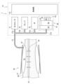
- FIG. 1 is a diagram showing a block configuration of a sphygmomanometer according to an embodiment of the present invention
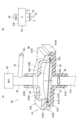
- Fig. 2A is a perspective view showing a cross-sectional structure of a Korotkoff sound detection device included in the blood pressure monitor
- Fig. 2B is a diagram showing a model for setting the resonance frequency of a chamber included in the Korotkoff sound detection device.
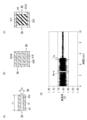
- Fig. 3(A), Fig. 3(B), and Fig. 3(C) are diagrams showing various aspects of a thin tube forming a pressure relief hole that allows fluid to flow between the inside and outside of the chamber, respectively.
- Fig. 3(D) is a diagram showing the verification result of noise reduction by accommodating a sound-proofing material inside the thin tube shown in Fig.
- 3(C). 2 is a diagram showing a state in which a pressure cuff of the blood pressure monitor is attached to an upper arm as a measurement site.
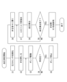
- FIG. FIG. 4 is a diagram showing a flow of blood pressure measurement using the sphygmomanometer.
- 6(A) and 6(B) are diagrams for explaining the operation of the Korotkoff sound detection device during blood pressure measurement.
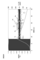
- 4 is a diagram illustrating an example of a sound signal output by the Korotkoff sound detection device in the blood pressure monitor (embodiment).
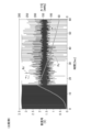
- FIG. 10A and 10B are diagrams illustrating sound signals output by a Korotkoff sound detection device of a comparative example.
- 9(A) and 9(B) are diagrams showing modified examples of the pressure relieving holes.
- FIG. 1 shows a block diagram of a blood pressure monitor 1 according to an embodiment of the present invention.
- This blood pressure monitor 1 is roughly divided into a pressure cuff (hereinafter simply referred to as a "cuff") 20 that is attached around a measurement site (in this example, the upper arm), and a main body 10 that is connected to this cuff 20 via an air pipe 37 so as to be capable of fluid communication.
- a pressure cuff hereinafter simply referred to as a "cuff” 20 that is attached around a measurement site (in this example, the upper arm)
- a main body 10 that is connected to this cuff 20 via an air pipe 37 so as to be capable of fluid communication.
- the cuff 20 includes a bag body 21, which is constructed by opposing an elongated strip-shaped outer cloth and an inner cloth, with their peripheral edges sewn (or welded). Inside this bag body 21 is housed a fluid bag 22 for applying pressure to the area to be measured.
- the main body 10 is equipped with a control unit 110, a display 50, an operation unit 52, a memory 51, a power supply unit 53, a pressure sensor 31, a pump 32, a valve 33, and a Korotkoff sound detection device 60 for extracting Korotkoff sounds from sounds generated by the measurement site.
- the main body 10 is further equipped with an A/D conversion circuit 310 that converts analog output from the pressure sensor 31 into a digital signal, a pump drive circuit 320 that drives the pump 32, a valve drive circuit 330 that drives the valve 33, and an A/D conversion circuit 410 that converts analog output from the Korotkoff sound detection device 60 into a digital signal.
- Air pipes 37a, 37b, 37c, and 37d are connected to the pressure sensor 31, the pump 32, the valve 33, and the Korotkoff sound detection device 60, respectively, so as to be capable of flowing fluid therethrough.
- These air pipes 37a, 37b, 37c, and 37d merge into one air pipe 37 inside the main body 10, and this air pipe 37 is connected to the fluid bag 22 inside the cuff 20 so that the fluid can flow through it.
- the air pipes 37a, 37b, 37c, and 37d will be collectively referred to as air pipes 37 as appropriate.
- the output of the Korotkoff sound detection device 60 is transmitted to the A/D conversion circuit 410 as a sound signal Ks, which is an electrical signal, by wiring 71.
- the display 50 includes a display and an indicator, and displays predetermined information (e.g., blood pressure measurement results) according to a control signal from the control unit 110.
- predetermined information e.g., blood pressure measurement results
- the operation unit 52 inputs an operation signal corresponding to an instruction from the user to the control unit 110.
- the operation unit 52 includes a measurement switch 52A for receiving an instruction to start/stop blood pressure measurement, and a memory switch 52B for receiving an instruction to call up the blood pressure measurement result data stored in the memory 51.
- Memory 51 serves as a storage unit and stores program data for controlling sphygmomanometer 1, setting data for setting various functions of sphygmomanometer 1, and blood pressure measurement result data. Memory 51 is also used as a work memory when a program is executed.
- the control unit 110 includes a CPU (Central Processing Unit) and controls the overall operation of the blood pressure monitor 1. Specifically, the control unit 110 acts as a pressure control unit in accordance with a program for controlling the blood pressure monitor 1 stored in the memory 51, and controls the operation of the pump 32 and the valve 33 in response to an operation signal from the operation unit 52. The control unit 110 also acts as a threshold setting unit and blood pressure calculation unit, calculates the blood pressure value of the measurement site based on the sound signal Ks output by the Korotkoff sound detection device 60, and controls the display 50 and memory 51. A specific method of measuring blood pressure will be described later.
- a CPU Central Processing Unit
- the power supply unit 53 supplies power to the control unit 110, the pressure sensor 31, the pump 32, the valve 33, the display 50, the memory 51, the A/D conversion circuits 310 and 410, the pump drive circuit 320, the valve drive circuit 330, and the microphone 40, which will be described later. Power is supplied to the microphone 40 through a wire 71.
- the pressure sensor 31 in this example is a piezo-resistive pressure sensor, which receives the pressure (called "cuff pressure Pc") of the cuff 20 (in this example, the fluid bag 22) through the air piping 37, and outputs an electrical signal value based on the change in electrical resistance due to the piezo-resistive effect to the control unit 110 through the A/D conversion circuit 310.
- the control unit 110 detects the cuff pressure Pc according to the electrical signal value from the pressure sensor 31.
- the pump 32 supplies air to the fluid bag 22 through the air pipe 37 to increase the cuff pressure Pc.
- the valve 33 opens and closes to control the cuff pressure Pc by discharging or sealing air in the fluid bag 22 through the air pipe 37.
- the pump drive circuit 320 drives the pump 32 based on a control signal provided by the control unit 110.
- the valve drive circuit 330 opens and closes the valve 33 based on a control signal provided by the control unit 110.
- the Korotkoff sound detection device 60 generally includes a roughly short cylindrical case 61, a diaphragm 62 arranged across the case 61, a microphone 40 as a sound detection device, and a thin tube 63 forming a hole for relieving pressure.
- FIG. 2(A) illustrates an example of a cross-sectional structure of a Korotkoff sound detection device 60.
- This Korotkoff sound detection device 60 has a case 61 including a lower case 61A and an upper case 61B.
- FIG. 2(A) shows a longitudinal section of the case 61 cut in half along a vertical plane. Note that the terms “lower”, “upper”, “vertical”, and “horizontal” (described below) are used for convenience of explanation, and the case 61 as a whole can be positioned in any orientation within the main body 10 of the sphygmomanometer 1.
- the lower case 61A includes a cylindrical portion 61A1 that fits around the air pipe 37d, a plate portion 61A2 that has a generally rectangular plate-like shape that extends horizontally from the upper end of the cylindrical portion 61A1, a recess 61A3 that is provided on the upper surface of the plate portion 61A2 as a circular depression with a flat bottom, and an edge portion 61A4 that bends and extends upward from the end edge (the right edge in FIG. 2(A)) of the plate portion 61A2.
- the cylindrical portion 61A1 fits airtight around the air pipe 37d.
- the space Cd that the recess 61A3 creates on the plate portion 61A2 is fluidically connected to the air pipe 37d (and therefore the air pipe 37) via the cylindrical portion 61A1.
- the horizontal dimension of the plate portion 61A2 is set to about 50 mm.
- the upper case 61B includes a substantially rectangular plate portion 61B1 extending substantially parallel to the plate portion 61A2 of the lower case 61A, a dome portion 61B2 protruding upward from the plate portion 61B1 in a circular dome shape, a cylindrical portion 61B3 extending upward from the approximate center of the dome portion 61B2, and an edge portion 61B4 bending downward from the end edge (the left edge in FIG. 2(A)) of the plate portion 61B1.
- the horizontal dimension of the plate portion 61B1 is set to approximately 50 mm, similar to that of the plate portion 61A2 of the lower case 61A.
- the horizontal position and dimensions of the dome portion 61B2 are substantially the same as those of the recess 61A3 of the lower case 61A.
- the air pipe 38 is inserted into the cylindrical portion 61B3 in an airtight fit.
- a microphone 40 is attached airtight to the upper end of the air pipe 38.
- a thin tube 63 is attached midway through the air pipe 38.
- the space Cm (forming a chamber, described below) formed by the inner periphery 61B1i of the plate portion 61B1 and the inner periphery 61B1i of the dome portion 61B2 is in fluid communication with the microphone 40 via the cylindrical portion 61B3 and the air pipe 38.
- a substantially circular membrane-like diaphragm 62 is provided so as to cross and separate the space Cd and the space Cm.
- the peripheral portion 62e of the diaphragm 62 is sandwiched between the plate portion 61A2 of the lower case 61A and the plate portion 61B1 of the upper case 61B.
- the portion of the diaphragm 62 other than the peripheral portion 62e can vibrate up and down as shown by the arrow Bs in FIG. 2(A).
- the peripheral portion 62e of the diaphragm 62 may be bonded to the plate portion 61A2 of the lower case 61A and/or the plate portion 61B1 of the upper case 61B with an adhesive.
- the diaphragm 62 is made of a polyurethane sheet (thickness 0.3 mm) as a synthetic resin.
- the natural frequency of the diaphragm 62 is set to match the frequency band of Korotkoff sounds (approximately 20 Hz to 500 Hz). Therefore, the diaphragm 62 can selectively transmit sounds in the frequency band of Korotkoff sounds.
- the edge 61A4 of the lower case 61A and the edge 61B4 of the upper case 61B are provided for the convenience of aligning the lower case 61A and the upper case 61B with each other in the horizontal plane when assembling the lower case 61A and the upper case 61B. Thanks to these edges 61A4, 61B4, the recess 61A3 of the lower case 61A and the dome portion 61B2 of the upper case 61B can be easily aligned concentrically.
- the upper surface 62b of the diaphragm 62, the inner peripheral edge 61B1i of the plate portion 61B1, the inner surface 61B2i of the dome portion 61B2, the cylindrical portion 61B3, and the air piping 38 form a chamber (for simplicity, represented by the same reference symbol as the space Cm).
- the chamber Cm is set to have a resonant frequency that matches the frequency band of Korotkoff sounds (approximately 20 Hz to 500 Hz).
- Fig. 2B shows a model of Helmholtz Resonance in a configuration in which the cylindrical portion 61B3 of the upper case 61B and the air pipe 38 are omitted and the chamber Cm is directly connected to the microphone 40 so as to be capable of fluid communication (note that in this case, the thin tube 63 may be directly attached to the dome portion 61B2 of the upper case 61B as shown in Fig. 1, or may be formed integrally with the dome portion 61B2).
- S represents the effective area of the diaphragm 62 (the area of the part that actually vibrates, in m2 )
- V represents the internal volume of the chamber Cm (in m3 )
- L represents the equivalent neck length (in m).
- c represents the speed of sound
- c is approximately 340 m/sec.
- the resonant frequency f of the chamber Cm is set to match the frequency band of Korotkoff sounds (approximately 20 Hz to 500 Hz) based on the formula (Eq. 1).
- the chamber Cm can selectively amplify sounds that have the frequency band of Korotkoff sounds among the sounds that have passed through the diaphragm 62.
- the microphone 40 receives the sound that has passed through the diaphragm 62 via the air occupying the chamber Cm and converts it into an electrical sound signal Ks.
- the sound signal Ks contains components that mainly represent Korotkoff sounds.
- the sound signal Ks is transmitted to the control unit 110 as the output of the Korotkoff sound detection device 60 via the wiring 71 and the A/D conversion circuit 410.
- the thin tube 63 forming the pressure relief hole has a cylindrical outer shape.
- a pressure relief hole 63o is provided inside the thin tube 63, which allows fluid to flow between the inside and outside of the chamber Cm.
- the hole 63o is in the form of a long, thin pipe that extends in a straight line.
- the axial dimension L of the thin tube 63 is set to a few mm to a few cm.
- the inner diameter Di of the hole 63o is set to about 0.1 mm to a few mm.
- the hole 63o allows air to flow between the inside and outside of the chamber Cm, as shown by the arrow Ai in FIG. 3(A), and acts to prevent the air pressure in the chamber Cm from changing from the atmospheric pressure (ambient pressure) Am. Therefore, even if the air pressure in the air pipe 37 (and space Cd) changes, it is possible to prevent the pressure change (load) from adversely affecting the sensitivity, resolution, durability, and reliability of the microphone 40.
- the pressure relief hole 63o is in the form of a long and thin pipe. Therefore, compared to when the hole 63o is, for example, a wide opening (not shown), noise is less likely to enter the chamber Cm from outside the chamber Cm through the hole 63o. This prevents the S/N ratio of the Korotkoff sound from decreasing due to the pressure relief hole.
- the hole 63o is straight, but this is not limited to this.
- the pressure relief hole 63oB provided therein is in the form of a long and thin pipe that moves back and forth in a zigzag pattern.
- the hole 63oB works to prevent the air pressure in the chamber Cm from changing from the atmospheric pressure Am by circulating air inside and outside the chamber Cm, as shown by the arrow AiB. Therefore, even if the air pressure in the air pipe 37 (and the space Cd) changes, it is possible to prevent the pressure change (load) from adversely affecting the sensitivity, resolution, durability, reliability, etc. of the microphone 40. Moreover, compared to the example in FIG. 3(A), noise is less likely to enter the chamber Cm from outside the chamber Cm through the hole 63oB. Therefore, it is possible to further prevent the S/N ratio of the Korotkoff sound from decreasing due to the pressure relief hole.
- the pressure relief hole 63oC provided therein is in the form of a long, thin pipe extending straight.
- the hole 63oC contains polyurethane foam 64, which is a porous material in this example, as a soundproofing material having breathability and soundproofing properties.
- This polyurethane foam 64 has breathability as shown by the arrow AiC. Therefore, the presence of the polyurethane foam 64 does not cause the function of the hole 63oC to suppress the change in the air pressure in the chamber Cm from the atmospheric pressure Am to be lost.
- FIG. 3D shows the results of verifying the extent to which noise in the chamber Cm is reduced by placing polyurethane foam 64 inside the hole 63oC when the axial dimension L of the capillary tube 63C is 2 mm and the inner diameter Di of the hole 63oC is approximately 0.2 mm.
- the background noise level (peak-to-peak) Ap-p in the chamber Cm was approximately 0.11 V.
- the background noise level Ap-p in the chamber Cm was reduced to approximately 0.02 V. In this way, it was verified that the presence of polyurethane foam 64 can effectively reduce noise in the chamber Cm.
- the cuff 20 When measuring blood pressure, as shown in Fig. 4, the cuff 20 is attached around the measurement site (upper arm in this example) 90 of the user (note that in Fig. 4, for simplicity, the illustration of the inner cloth is omitted). It is assumed that an artery 91 passes through the measurement site 90.
- the sound generated by the measurement site 90 includes not only Korotkoff sounds (frequency band: about 20 Hz to 500 Hz) but also pressure pulse waves (frequency band: about several tens of Hz) dV, which are pulse wave vibrations of the artery 91 passing through the measurement site 90.
- the sound generated by the measurement site 90 is transmitted from the space Cc created by the fluid bag 22 through the air piping 37 to the Korotkoff sound detection device 60 (space Cd) in the main body 10.
- FIG. 5 shows the operational flow when a user measures blood pressure using the blood pressure monitor 1.
- the control unit 110 When the cuff 20 is attached to the part to be measured and the user issues an instruction to start measurement using the measurement switch 52A of the operation unit 52 provided on the main body 10, the control unit 110 performs initialization (step S1 in FIG. 5). Specifically, the control unit 110 initializes the processing memory area, turns off (stops) the pump 32, and adjusts the pressure sensor 31 to 0 mmHg (setting the atmospheric pressure to 0 mmHg) with the valve 33 open. In this initial state, the diaphragm 62 of the Korotkoff sound detection device 60 is in a flat state, as shown in FIG. 6 (A).
- control unit 110 acting as a pressure control unit, closes the valve 33 via the valve drive circuit 330 (step S2 in FIG. 5), and then turns on (drives) the pump 32 via the pump drive circuit 320 to start pressurizing the cuff 20 (fluid bag 22) (step S3). That is, the control unit 110 supplies air as a fluid from the pump 32 through the air piping 37 to the fluid bag 22 in the cuff 20. At the same time, the pressure sensor 31 receives the cuff pressure Pc through the air piping 37. The control unit 110 controls the pressurization speed by the pump 32 based on the output of the pressure sensor 31.
- the diaphragm 62 of the Korotkoff sound detection device 60 receives the air pressure in the air pipe 37 (particularly, the air pipe 37d) on one surface 62a (the surface on the side of space Cd) and bends convexly toward the other surface 62b. This blocks the air pressure in the air pipe 37. Furthermore, when the air pressure in the chamber Cm attempts to change due to the bending of the diaphragm 62, the pressure relief hole 63o of the thin tube 63 allows air to circulate between the inside and outside of the chamber Cm, as shown by the arrow Ai, and acts to prevent the air pressure in the chamber Cm from changing from the atmospheric pressure Am.
- step S4 of FIG. 5 the control unit 110 determines whether the cuff pressure Pc has reached a predetermined value (predetermined pressure) based on the output of the pressure sensor 31.
- this predetermined pressure may be set to, for example, 180 mmHg so as to be sufficiently higher than the expected blood pressure value of the user, or may be set to the user's previously measured blood pressure value plus 40 mmHg.
- the control unit 110 continues to inflate the cuff pressure Pc until it reaches the above-mentioned predetermined pressure, and when the cuff pressure Pc reaches the above-mentioned predetermined pressure (YES in step S4), it stops the pump 32 (step S5).
- the control unit 110 gradually opens the valve 33 via the valve drive circuit 330 (step S6). This reduces the cuff pressure Pc at a substantially constant rate.
- the diaphragm 62 receives the air pressure in the air pipe 37 on one surface 62a, blocking the air pressure in the air pipe 37 and vibrating as shown by arrow Bs, allowing sound in the frequency band of Korotkoff sounds to pass through the diaphragm 62.
- the sound that passes through the diaphragm 62 is transmitted to the air occupying the chamber Cm.
- the microphone 40 receives the sound that has passed through the diaphragm 62 via the air occupying the chamber Cm, converts it into an electrical sound signal Ks, and outputs it via the wiring 71.
- the diaphragm 62 blocks the air pressure in the air piping 37, so the influence of the pressure pulse wave dV, which is the pulse wave vibration of the artery 91, on the sound generated by the measured part 90 can be reduced. Furthermore, the microphone 40 receives the sound that has passed through the diaphragm 62 via the air occupying the chamber Cm, in other words, at a position separated from the diaphragm 62 (which directly receives the pressure pulse wave). Therefore, the influence of the pressure pulse wave dV can be further reduced. This makes it possible to remove noise due to the pressure pulse wave dV from the sound generated by the measured part 90.
- the diaphragm 62 is set to have a natural frequency that matches the frequency band of Korotkoff sounds, so it can selectively transmit sounds that have the frequency band of Korotkoff sounds from among the sounds that have been transmitted from the measurement site 90 through the air in the air piping 37 (and space Cd).
- the chamber Cm is set to have a resonant frequency that matches the frequency band of Korotkoff sounds, so it can selectively amplify sounds that have the frequency band of Korotkoff sounds from among the sounds that have been transmitted through the diaphragm 62. Therefore, the Korotkoff sounds can be extracted with a good signal-to-noise ratio.
- step S7 Kerrotkoff sound extraction process
- the control unit 110 acquires the sound signal Ks output by the Korotkoff sound detection device 60 (microphone 40) via the A/D conversion circuit 410, and extracts a signal representing the Korotkoff sound (called the "Korotkoff sound signal Kc") from the sound signal Ks.
- FIG. 7 illustrates the sound signal Ks output by the Korotkoff sound detection device 60.
- the mountain-shaped curve in FIG. 7 represents the cuff pressure Pc.
- the cuff pressure Pc reaches a predetermined pressure of 180 mmHg about 17 seconds after the start of pressurization, and the depressurization process starts from that point.
- the sound signal Ks contains multiple pulse-shaped Korotkoff sound signals Kc that exceed the background noise level Ap-p (about 0.02 V in this example).
- the control unit 110 works as a threshold setting unit and sets a threshold TH (about 0.06 V in this example) that exceeds the background noise level Ap-p for the sound signal Ks.
- the control unit 110 extracts only the signals from the sound signal Ks that exceed the threshold TH as the Korotkoff sound signal Kc. This makes it possible to remove background noise from the sound signal Ks. Therefore, the S/N ratio of the Korotkoff sound can be further improved.
- the memory 51 stores the amplitude of the extracted Korotkoff sound signal Kc in association with the time at which the Korotkoff sound signal Kc was generated.
- the control unit 110 functions as a blood pressure calculation unit and calculates the blood pressure at the measurement site based on the Korotkoff sound signal Kc stored in the memory 51. Specifically, in the above decompression process, the cuff pressure Pc at the time when the Korotkoff sound signal Kc first appears is determined as the systolic blood pressure SYS (Systolic Blood Pressure), and the cuff pressure Pc at the time when the Korotkoff sound signal Kc last appears is determined as the diastolic blood pressure DIA (Diastolic Blood Pressure).
- SYS Systolic Blood Pressure
- DIA Diastolic Blood Pressure
- the control unit 110 functions as a pressure control unit, turns off the pump 32, opens the valve 33, and performs control to rapidly exhaust the air in the cuff 20 (fluid bag 22) (step S10). After this, the control unit 110 displays the calculated blood pressure values on the display 50 and performs control to store them in the memory 51.
- this blood pressure measurement method makes it possible to extract Korotkoff sounds with a good signal-to-noise ratio from the sounds generated by the measurement site 90, thereby improving the accuracy of blood pressure measurement.
- FIG. 8 illustrates the sound signal Ks' output by the Korotkoff sound detector.
- the cuff pressure Pc reaches a predetermined pressure of 180 mmHg about 17 seconds after the start of pressurization, and the depressurization process begins from that point.
- the diaphragm 62 of the Korotkoff sound detection device 60 gradually attempts to return from the state in which it is bent convexly toward the other surface 62b as shown in FIG. 6(B) to the flat state shown in FIG. 6(A).
- the pressure relief hole 63o of the thin tube 63 allows air to circulate between the inside and outside of the chamber Cm as shown by the arrow Ai, and acts to prevent the air pressure in the chamber Cm from changing from the atmospheric pressure Am.
- the air pressure in chamber Cm is prevented from changing from atmospheric pressure Am not only during the pressurization process (steps S3 to S4 in FIG. 5) but also during the depressurization process (steps S6 to S9 in FIG. 5).
- various types of microphones such as not only condenser microphones but also dynamic microphones and MEMS (Micro Electronics Mechanical System) microphones, can be used as microphone 40, increasing the freedom of microphone selection.
- the pressure relief holes 63o, 63oB, and 63oC for the chamber Cm are in the form of elongated conduits provided inside the capillaries 63, 63B, and 63C, but are not limited to this.
- the pressure relief holes may be in the form of elongated grooves 41d and 61B2d shown in Fig. 9(A) or elongated grooves 61B1d shown in Fig. 9(B).
- Fig. 9(A) and Fig. 9(B) components corresponding to those already described are given the same reference numerals, and duplicated explanations will be omitted.
- the cylindrical portion 61B3 of the upper case 61B and the air piping 38 are omitted from the example of Figure 2(A). Instead, a through hole 61B2o is provided at the top of the dome portion 61B2 of the upper case 61B, and a commercially available MEMS microphone 40A having a flat, approximately rectangular parallelepiped shape is closely attached to the top surface of the dome portion 61B2 via a substrate 41 having a through hole 41o.
- the chamber Cm is fluidically connected to the microphone 40A via the through-hole 61B2o of the dome portion 61B2 and the through-hole 41o of the substrate 41.
- the microphone 40A can receive the sound that has passed through the diaphragm 62 via the air that occupies the chamber Cm, convert it into an electrical sound signal Ks, and output it.
- the dimensions of the microphone 40A in the planar direction are several mm square.
- the pressure relief hole for the chamber Cm consists of an elongated groove 61B2d formed in the top surface of the dome portion 61B2 of the upper case 61B, and an elongated groove 41d formed in a position on the underside of the substrate 41 (the surface in contact with the dome portion 61B2) that overlaps with and corresponds to the elongated groove 61B2d.
- the pressure change (load) can be prevented from adversely affecting the sensitivity, resolution, durability, and reliability of the microphone 40A.
- one of the elongated grooves 41d and 61B2d may be omitted.
- the pressure relief hole for the chamber Cm consists of a long and narrow groove 61B1d formed in the underside (the surface in contact with the diaphragm 62) of the plate portion 61B1 of the upper case 61B.
- the diaphragm 62 flexes as the air pressure in the air piping 37 (and space Cd) gradually changes during the pressurization or depressurization process of the cuff 20, causing the air pressure in the chamber Cm to change, this long and narrow groove 61B1d, as shown by the arrows AiE in FIG.
- the elongated grooves 41d, 61B2d shown in FIG. 9(A) and the elongated grooves 61B1d shown in FIG. 9(B) may be filled with a sound-proofing material (e.g., polyurethane foam) that is breathable and has sound-proofing properties. This makes it possible to prevent the elongated grooves 41d, 61B2d, or 61B1d from lowering the S/N ratio of the Korotkoff sound.
- a sound-proofing material e.g., polyurethane foam
- blood pressure measurement using the sphygmomanometer 1 may be performed during the pressurization process rather than the depressurization process.
- the part to be measured is not limited to the upper arm, but may be an upper limb other than the upper arm, such as the wrist, or a lower limb, such as the ankle.
Landscapes
- Health & Medical Sciences (AREA)
- Life Sciences & Earth Sciences (AREA)
- Cardiology (AREA)
- Vascular Medicine (AREA)
- Biomedical Technology (AREA)
- Heart & Thoracic Surgery (AREA)
- Physiology (AREA)
- Biophysics (AREA)
- Pathology (AREA)
- Engineering & Computer Science (AREA)
- Veterinary Medicine (AREA)
- Physics & Mathematics (AREA)
- Medical Informatics (AREA)
- Molecular Biology (AREA)
- Surgery (AREA)
- Animal Behavior & Ethology (AREA)
- General Health & Medical Sciences (AREA)
- Public Health (AREA)
- Ophthalmology & Optometry (AREA)
- Measuring Pulse, Heart Rate, Blood Pressure Or Blood Flow (AREA)
Abstract
Description
被測定部位が発生するコロトコフ音に基づいて血圧を測定する血圧計であって、
上記被測定部位に装着されるように構成された押圧用カフと、
ポンプと、
上記カフと上記ポンプとを流体流通可能に連結するエア配管と、
上記被測定部位を圧迫するために上記ポンプによって上記エア配管を通して上記カフに空気を供給して加圧し、または、上記カフから上記エア配管を通して上記空気を排出して減圧する圧力制御部と、
上記エア配管の管壁の一部として又は上記管壁に連なって、上記エア配管内の空気の圧力を一方の面に受けるように配置されたダイヤフラムを備え、上記ダイヤフラムは、上記圧力制御部による上記カフの加圧過程または減圧過程で、上記エア配管内の空気の圧力を遮断する一方、上記被測定部位から上記エア配管内の空気を通して伝わってきた音のうち上記コロトコフ音の周波数帯域の音をこのダイヤフラムを通して透過させるように構成され、
上記ダイヤフラムに関して上記一方の面と反対の他方の面の側に、上記ダイヤフラムを周壁の一部として含んで配置されたチャンバを備え、上記ダイヤフラムを透過した音は、上記チャンバ内を占める空気に伝わるようになっており、
上記チャンバの上記周壁のうち上記ダイヤフラム以外の部分に、上記チャンバ内の空気に面して設けられた音検出デバイスを備え、上記音検出デバイスは、上記ダイヤフラムを透過した音を、上記チャンバ内を占める空気を介して受けて電気信号に変換するようになっており、
上記電気信号に基づいて、上記被測定部位の血圧を算出する血圧算出部を備えた
ことを特徴とする。
上記チャンバの上記周壁のうち上記ダイヤフラム以外の部分に、上記チャンバの内外を流体流通可能に連通する圧力緩和用の孔が設けられ、上記圧力緩和用の孔は、上記チャンバ内の空気の圧力が大気圧から変化するのを抑えるように働く
ことを特徴とする。
上記圧力緩和用の孔は、細長い管路または細長い溝の形態を有する
ことを特徴とする。
上記細長い管路または上記細長い溝の内部に、通気性および遮音性を有する遮音材が収容されている
ことを特徴とする。
上記ダイヤフラムは、上記コロトコフ音の周波数帯域に合った固有振動数をもつように設定されている
ことを特徴とする。
上記チャンバは、上記コロトコフ音の周波数帯域に合った共振周波数をもつように設定されている
ことを特徴とする。
上記ダイヤフラムは合成樹脂からなっている
ことを特徴とする。
上記音検出デバイスが出力する上記電気信号に、上記コロトコフ音を抽出するための閾値を設定する閾値設定部を備え、
上記血圧算出部は、上記電気信号のうち上記閾値を超える信号のみに基づいて、上記被測定部位の血圧を算出する
ことを特徴とする。
上記血圧計によって、被測定部位が発生するコロトコフ音に基づいて血圧を測定する血圧測定方法であって、
上記被測定部位に上記押圧用カフが装着された状態で、上記圧力制御部が、上記被測定部位を圧迫するために上記ポンプによって上記エア配管を通して上記カフに空気を供給して加圧し、または、上記カフから上記エア配管を通して上記空気を排出して減圧し、
上記圧力制御部による上記カフの加圧過程または減圧過程で、上記ダイヤフラムが、上記エア配管内の空気の圧力を一方の面に受けて、上記エア配管内の空気の圧力を遮断するとともに、上記被測定部位から上記エア配管内の空気を通して伝わってきた音のうち上記コロトコフ音の周波数帯域の音をこのダイヤフラムを通して透過させ、その結果、上記ダイヤフラムを透過した音は、上記チャンバ内を占める空気に伝わり、
上記音検出デバイスは、上記ダイヤフラムを透過した音を、上記チャンバ内を占める空気を介して受けて電気信号に変換し、
上記血圧算出部は、上記電気信号に基づいて、上記被測定部位の血圧を算出する
ことを特徴とする。
上記血圧計に含まれ、上記被測定部位が発生する音からコロトコフ音を抽出するコロトコフ音検出装置であって、
上記エア配管の管壁の一部として又は上記管壁に連なって、上記エア配管内の空気の圧力を一方の面に受けるように配置されたダイヤフラムを備え、上記ダイヤフラムは、上記圧力制御部による上記カフの加圧過程または減圧過程で、上記エア配管内の空気の圧力を遮断する一方、上記被測定部位から上記エア配管内の空気を通して伝わってきた音のうち上記コロトコフ音の周波数帯域の音をこのダイヤフラムを通して透過させるように構成され、
上記ダイヤフラムに関して上記一方の面と反対の他方の面の側に、上記ダイヤフラムを周壁の一部として含んで配置されたチャンバを備え、上記ダイヤフラムを透過した音は、上記チャンバ内を占める空気に伝わるようになっており、
上記チャンバの上記周壁のうち上記ダイヤフラム以外の部分に、上記チャンバ内の空気に面して設けられた音検出デバイスを備え、上記音検出デバイスは、上記ダイヤフラムを透過した音を、上記チャンバ内を占める空気を介して受けて電気信号に変換するようになっている
ことを特徴とする。
図1は、この発明の一実施形態の血圧計1のブロック構成を示している。この血圧計1は、大別して、被測定部位(この例では、上腕)を取り巻いて装着される押圧用カフ(以下、単に「カフ」と呼ぶ。)20と、このカフ20に対してエア配管37を介して流体流通可能に接続された本体10とを備えている。
f=(c/2π)(S/VL)1/2 …(Eq.1)
によって算出される。ここで、cは音速を表し、c≒340m/secである。この例では、式(Eq.1)に基づいて、チャンバCmの共振周波数fがコロトコフ音の周波数帯域(20Hz~500Hz程度)に合うように設定されている。
血圧測定に際して、図4に示すように、カフ20は、ユーザの被測定部位(この例では、上腕)90を取り巻いて装着される(なお、図4では、簡単のため、内布の図示が省略されている。)。被測定部位90には動脈91が通っているものとする。被測定部位90が発生する音には、コロトコフ音(周波数帯域;20Hz~500Hz程度)に加えて、被測定部位90を通る動脈91の脈波振動である圧脈波(周波数帯域;数十Hz程度)dVも含まれている。被測定部位90が発生する音は、流体袋22が作る空間Ccから、エア配管37を通して、本体10内のコロトコフ音検出装置60(の空間Cd)に伝わるようになっている。
上の例では、チャンバCmのための圧力緩和用の孔63o,63oB,63oCは、細管63,63B,63Cの内部に設けられた細長い管路の形態にあるものとしたが、これに限られるものではない。圧力緩和用の孔は、例えば、図9(A)中に示す細長い溝41d,61B2d、または、図9(B)中に示す細長い溝61B1dの形態にあってもよい。なお、図9(A)、図9(B)において、既述の構成要素に対応する構成要素には同じ符号を付して、重複する説明を省略する。
10 本体
20 カフ
22 流体袋
31 圧力センサ
32 ポンプ
33 弁
40,40A マイクロフォン
41 基板
41d,61B1d,61B2d 細長い溝
60,60′,60″ コロトコフ音検出装置
62 ダイヤフラム
63,63A,63B,63C 細管
63o,63oB,63oC 圧力緩和用の孔
64 ポリウレタンフォーム
Claims (10)
- 被測定部位が発生するコロトコフ音に基づいて血圧を測定する血圧計であって、
上記被測定部位に装着されるように構成された押圧用カフと、
ポンプと、
上記カフと上記ポンプとを流体流通可能に連結するエア配管と、
上記被測定部位を圧迫するために上記ポンプによって上記エア配管を通して上記カフに空気を供給して加圧し、または、上記カフから上記エア配管を通して上記空気を排出して減圧する圧力制御部と、
上記エア配管の管壁の一部として又は上記管壁に連なって、上記エア配管内の空気の圧力を一方の面に受けるように配置されたダイヤフラムを備え、上記ダイヤフラムは、上記圧力制御部による上記カフの加圧過程または減圧過程で、上記エア配管内の空気の圧力を遮断する一方、上記被測定部位から上記エア配管内の空気を通して伝わってきた音のうち上記コロトコフ音の周波数帯域の音をこのダイヤフラムを通して透過させるように構成され、
上記ダイヤフラムに関して上記一方の面と反対の他方の面の側に、上記ダイヤフラムを周壁の一部として含んで配置されたチャンバを備え、上記ダイヤフラムを透過した音は、上記チャンバ内を占める空気に伝わるようになっており、
上記チャンバの上記周壁のうち上記ダイヤフラム以外の部分に、上記チャンバ内の空気に面して設けられた音検出デバイスを備え、上記音検出デバイスは、上記ダイヤフラムを透過した音を、上記チャンバ内を占める空気を介して受けて電気信号に変換するようになっており、
上記電気信号に基づいて、上記被測定部位の血圧を算出する血圧算出部を備えた
ことを特徴とする血圧計。 - 請求項1に記載の血圧計において、
上記チャンバの上記周壁のうち上記ダイヤフラム以外の部分に、上記チャンバの内外を流体流通可能に連通する圧力緩和用の孔が設けられ、上記圧力緩和用の孔は、上記チャンバ内の空気の圧力が大気圧から変化するのを抑えるように働く
ことを特徴とする血圧計。 - 請求項2に記載の血圧計において、
上記圧力緩和用の孔は、細長い管路または細長い溝の形態を有する
ことを特徴とする血圧計。 - 請求項3に記載の血圧計において、
上記細長い管路または上記細長い溝の内部に、通気性および遮音性を有する遮音材が収容されている
ことを特徴とする血圧計。 - 請求項1から4までのいずれか一つに記載の血圧計において、
上記ダイヤフラムは、上記コロトコフ音の周波数帯域に合った固有振動数をもつように設定されている
ことを特徴とする血圧計。 - 請求項1から4までのいずれか一つに記載の血圧計において、
上記チャンバは、上記コロトコフ音の周波数帯域に合った共振周波数をもつように設定されている
ことを特徴とする血圧計。 - 請求項1から4までのいずれか一つに記載の血圧計において、
上記ダイヤフラムは合成樹脂からなっている
ことを特徴とする血圧計。 - 請求項1から4までのいずれか一つに記載の血圧計において、
上記音検出デバイスが出力する上記電気信号に、上記コロトコフ音を抽出するための閾値を設定する閾値設定部を備え、
上記血圧算出部は、上記電気信号のうち上記閾値を超える信号のみに基づいて、上記被測定部位の血圧を算出する
ことを特徴とする血圧計。 - 請求項1に記載の血圧計によって、被測定部位が発生するコロトコフ音に基づいて血圧を測定する血圧測定方法であって、
上記被測定部位に上記押圧用カフが装着された状態で、上記圧力制御部が、上記被測定部位を圧迫するために上記ポンプによって上記エア配管を通して上記カフに空気を供給して加圧し、または、上記カフから上記エア配管を通して上記空気を排出して減圧し、
上記圧力制御部による上記カフの加圧過程または減圧過程で、上記ダイヤフラムが、上記エア配管内の空気の圧力を一方の面に受けて、上記エア配管内の空気の圧力を遮断するとともに、上記被測定部位から上記エア配管内の空気を通して伝わってきた音のうち上記コロトコフ音の周波数帯域の音をこのダイヤフラムを通して透過させ、その結果、上記ダイヤフラムを透過した音は、上記チャンバ内を占める空気に伝わり、
上記音検出デバイスは、上記ダイヤフラムを透過した音を、上記チャンバ内を占める空気を介して受けて電気信号に変換し、
上記血圧算出部は、上記電気信号に基づいて、上記被測定部位の血圧を算出する
ことを特徴とする血圧測定方法。 - 請求項1に記載の血圧計に含まれ、上記被測定部位が発生する音からコロトコフ音を抽出するコロトコフ音検出装置であって、
上記エア配管の管壁の一部として又は上記管壁に連なって、上記エア配管内の空気の圧力を一方の面に受けるように配置されたダイヤフラムを備え、上記ダイヤフラムは、上記圧力制御部による上記カフの加圧過程または減圧過程で、上記エア配管内の空気の圧力を遮断する一方、上記被測定部位から上記エア配管内の空気を通して伝わってきた音のうち上記コロトコフ音の周波数帯域の音をこのダイヤフラムを通して透過させるように構成され、
上記ダイヤフラムに関して上記一方の面と反対の他方の面の側に、上記ダイヤフラムを周壁の一部として含んで配置されたチャンバを備え、上記ダイヤフラムを透過した音は、上記チャンバ内を占める空気に伝わるようになっており、
上記チャンバの上記周壁のうち上記ダイヤフラム以外の部分に、上記チャンバ内の空気に面して設けられた音検出デバイスを備え、上記音検出デバイスは、上記ダイヤフラムを透過した音を、上記チャンバ内を占める空気を介して受けて電気信号に変換するようになっている
ことを特徴とするコロトコフ音検出装置。
Priority Applications (3)
| Application Number | Priority Date | Filing Date | Title |
|---|---|---|---|
| CN202380053386.XA CN119546226A (zh) | 2022-10-25 | 2023-08-08 | 血压计、血压测定方法及柯氏音检测装置 |
| DE112023004456.2T DE112023004456T5 (de) | 2022-10-25 | 2023-08-08 | Sphygmomanometer, verfahren zur blutdruckmessung und korotkoff-geräuschdetektionsvorrichtung |
| US19/008,850 US20250134401A1 (en) | 2022-10-25 | 2025-01-03 | Sphygmomanometer, blood pressure measurement method, and korotkoff sound detection device |
Applications Claiming Priority (2)
| Application Number | Priority Date | Filing Date | Title |
|---|---|---|---|
| JP2022-170781 | 2022-10-25 | ||
| JP2022170781A JP2024062735A (ja) | 2022-10-25 | 2022-10-25 | 血圧計、血圧測定方法およびコロトコフ音検出装置 |
Related Child Applications (1)
| Application Number | Title | Priority Date | Filing Date |
|---|---|---|---|
| US19/008,850 Continuation US20250134401A1 (en) | 2022-10-25 | 2025-01-03 | Sphygmomanometer, blood pressure measurement method, and korotkoff sound detection device |
Publications (1)
| Publication Number | Publication Date |
|---|---|
| WO2024089976A1 true WO2024089976A1 (ja) | 2024-05-02 |
Family
ID=90830526
Family Applications (1)
| Application Number | Title | Priority Date | Filing Date |
|---|---|---|---|
| PCT/JP2023/028940 Ceased WO2024089976A1 (ja) | 2022-10-25 | 2023-08-08 | 血圧計、血圧測定方法およびコロトコフ音検出装置 |
Country Status (5)
| Country | Link |
|---|---|
| US (1) | US20250134401A1 (ja) |
| JP (1) | JP2024062735A (ja) |
| CN (1) | CN119546226A (ja) |
| DE (1) | DE112023004456T5 (ja) |
| WO (1) | WO2024089976A1 (ja) |
Citations (4)
| Publication number | Priority date | Publication date | Assignee | Title |
|---|---|---|---|---|
| JPS4948686U (ja) * | 1972-07-31 | 1974-04-27 | ||
| JPS58180132A (ja) * | 1982-04-15 | 1983-10-21 | 松下電工株式会社 | コロトコフ音検出装置 |
| JPH0219134A (ja) * | 1988-07-07 | 1990-01-23 | Koorin Denshi Kk | 血圧連続測定装置 |
| JP2008093360A (ja) * | 2006-10-16 | 2008-04-24 | Nippon Seimitsu Sokki Kk | コンデンサマイクロホン、マイクロホンユニット、及び血圧計 |
-
2022
- 2022-10-25 JP JP2022170781A patent/JP2024062735A/ja active Pending
-
2023
- 2023-08-08 CN CN202380053386.XA patent/CN119546226A/zh active Pending
- 2023-08-08 DE DE112023004456.2T patent/DE112023004456T5/de active Pending
- 2023-08-08 WO PCT/JP2023/028940 patent/WO2024089976A1/ja not_active Ceased
-
2025
- 2025-01-03 US US19/008,850 patent/US20250134401A1/en active Pending
Patent Citations (4)
| Publication number | Priority date | Publication date | Assignee | Title |
|---|---|---|---|---|
| JPS4948686U (ja) * | 1972-07-31 | 1974-04-27 | ||
| JPS58180132A (ja) * | 1982-04-15 | 1983-10-21 | 松下電工株式会社 | コロトコフ音検出装置 |
| JPH0219134A (ja) * | 1988-07-07 | 1990-01-23 | Koorin Denshi Kk | 血圧連続測定装置 |
| JP2008093360A (ja) * | 2006-10-16 | 2008-04-24 | Nippon Seimitsu Sokki Kk | コンデンサマイクロホン、マイクロホンユニット、及び血圧計 |
Also Published As
| Publication number | Publication date |
|---|---|
| US20250134401A1 (en) | 2025-05-01 |
| DE112023004456T5 (de) | 2025-08-07 |
| JP2024062735A (ja) | 2024-05-10 |
| CN119546226A (zh) | 2025-02-28 |
Similar Documents
| Publication | Publication Date | Title |
|---|---|---|
| US12507901B2 (en) | Integrated flexible sensor for blood pressure measurements | |
| US8579826B2 (en) | Arteriosclerosis degree judgment device capable of judging arteriosclerosis degree precisely | |
| JP5101897B2 (ja) | 血圧測定装置、カフ及びカフの製造方法 | |
| US8905940B2 (en) | Flow rate control valve and blood pressure information measurement device including the same | |
| US9072436B2 (en) | Device for measuring information regarding blood pressure | |
| JP2010522610A (ja) | 液体充填カフを備える動脈圧測定機 | |
| KR20100021515A (ko) | 혈압 측정 장치 | |
| CN101925327B (zh) | 血压测量装置 | |
| JP2020006208A (ja) | 時計型血圧測定装置 | |
| US20190000392A1 (en) | Electronic Blood Pressure Monitor, Blood Pressure Measuring Method, and Electronic Stethoscope | |
| CN101534705A (zh) | 非侵入式血压监视系统 | |
| JP4943870B2 (ja) | 血圧測定装置及びカフ | |
| JP2009284965A (ja) | 血圧情報測定装置 | |
| JP2007044362A (ja) | 血圧脈波検査用カフ | |
| WO2011105195A1 (ja) | 血圧情報測定装置および血圧情報測定装置用カフの装着状態判別方法 | |
| JP2024062735A (ja) | 血圧計、血圧測定方法およびコロトコフ音検出装置 | |
| WO2023008104A1 (ja) | 電子血圧計および血圧測定方法 | |
| EP2842482A1 (en) | Blood pressure gauge with micro-electro-mechanical system (mems) microphone | |
| JP2012152372A (ja) | 血圧測定装置および血圧測定方法 | |
| JP2008307181A (ja) | 血圧測定装置 | |
| JP2011200610A (ja) | 電子血圧計 | |
| JP3716326B2 (ja) | 脈圧測定装置 | |
| JP3831899B2 (ja) | 脈波伝播速度測定装置 | |
| JP5600023B2 (ja) | 電子血圧計 | |
| WO2004069049A1 (ja) | 血圧脈波測定装置及び血圧脈波測定用装着具 |
Legal Events
| Date | Code | Title | Description |
|---|---|---|---|
| 121 | Ep: the epo has been informed by wipo that ep was designated in this application |
Ref document number: 23882192 Country of ref document: EP Kind code of ref document: A1 |
|
| WWE | Wipo information: entry into national phase |
Ref document number: 202380053386.X Country of ref document: CN |
|
| WWP | Wipo information: published in national office |
Ref document number: 202380053386.X Country of ref document: CN |
|
| WWE | Wipo information: entry into national phase |
Ref document number: 112023004456 Country of ref document: DE |
|
| WWP | Wipo information: published in national office |
Ref document number: 112023004456 Country of ref document: DE |
|
| 122 | Ep: pct application non-entry in european phase |
Ref document number: 23882192 Country of ref document: EP Kind code of ref document: A1 |