WO2024089968A1 - 画像処理装置、撮像装置、画像処理方法、およびプログラム - Google Patents
画像処理装置、撮像装置、画像処理方法、およびプログラム Download PDFInfo
- Publication number
- WO2024089968A1 WO2024089968A1 PCT/JP2023/028690 JP2023028690W WO2024089968A1 WO 2024089968 A1 WO2024089968 A1 WO 2024089968A1 JP 2023028690 W JP2023028690 W JP 2023028690W WO 2024089968 A1 WO2024089968 A1 WO 2024089968A1
- Authority
- WO
- WIPO (PCT)
- Prior art keywords
- event
- image
- imaging
- image processing
- optical member
- Prior art date
- Legal status (The legal status is an assumption and is not a legal conclusion. Google has not performed a legal analysis and makes no representation as to the accuracy of the status listed.)
- Ceased
Links
Images


Classifications
-
- H—ELECTRICITY
- H04—ELECTRIC COMMUNICATION TECHNIQUE
- H04N—PICTORIAL COMMUNICATION, e.g. TELEVISION
- H04N23/00—Cameras or camera modules comprising electronic image sensors; Control thereof
- H04N23/60—Control of cameras or camera modules
- H04N23/69—Control of means for changing angle of the field of view, e.g. optical zoom objectives or electronic zooming
-
- G—PHYSICS
- G02—OPTICS
- G02B—OPTICAL ELEMENTS, SYSTEMS OR APPARATUS
- G02B7/00—Mountings, adjusting means, or light-tight connections, for optical elements
- G02B7/28—Systems for automatic generation of focusing signals
- G02B7/36—Systems for automatic generation of focusing signals using image sharpness techniques, e.g. image processing techniques for generating autofocus signals
-
- G—PHYSICS
- G03—PHOTOGRAPHY; CINEMATOGRAPHY; ANALOGOUS TECHNIQUES USING WAVES OTHER THAN OPTICAL WAVES; ELECTROGRAPHY; HOLOGRAPHY
- G03B—APPARATUS OR ARRANGEMENTS FOR TAKING PHOTOGRAPHS OR FOR PROJECTING OR VIEWING THEM; APPARATUS OR ARRANGEMENTS EMPLOYING ANALOGOUS TECHNIQUES USING WAVES OTHER THAN OPTICAL WAVES; ACCESSORIES THEREFOR
- G03B5/00—Adjustment of optical system relative to image or object surface other than for focusing
-
- H—ELECTRICITY
- H04—ELECTRIC COMMUNICATION TECHNIQUE
- H04N—PICTORIAL COMMUNICATION, e.g. TELEVISION
- H04N23/00—Cameras or camera modules comprising electronic image sensors; Control thereof
- H04N23/50—Constructional details
- H04N23/54—Mounting of pick-up tubes, electronic image sensors, deviation or focusing coils
-
- H—ELECTRICITY
- H04—ELECTRIC COMMUNICATION TECHNIQUE
- H04N—PICTORIAL COMMUNICATION, e.g. TELEVISION
- H04N23/00—Cameras or camera modules comprising electronic image sensors; Control thereof
- H04N23/50—Constructional details
- H04N23/55—Optical parts specially adapted for electronic image sensors; Mounting thereof
-
- H—ELECTRICITY
- H04—ELECTRIC COMMUNICATION TECHNIQUE
- H04N—PICTORIAL COMMUNICATION, e.g. TELEVISION
- H04N23/00—Cameras or camera modules comprising electronic image sensors; Control thereof
- H04N23/58—Means for changing the camera field of view without moving the camera body, e.g. nutating or panning of optics or image sensors
-
- H—ELECTRICITY
- H04—ELECTRIC COMMUNICATION TECHNIQUE
- H04N—PICTORIAL COMMUNICATION, e.g. TELEVISION
- H04N23/00—Cameras or camera modules comprising electronic image sensors; Control thereof
- H04N23/60—Control of cameras or camera modules
-
- H—ELECTRICITY
- H04—ELECTRIC COMMUNICATION TECHNIQUE
- H04N—PICTORIAL COMMUNICATION, e.g. TELEVISION
- H04N23/00—Cameras or camera modules comprising electronic image sensors; Control thereof
- H04N23/60—Control of cameras or camera modules
- H04N23/67—Focus control based on electronic image sensor signals
- H04N23/675—Focus control based on electronic image sensor signals comprising setting of focusing regions
-
- H—ELECTRICITY
- H04—ELECTRIC COMMUNICATION TECHNIQUE
- H04N—PICTORIAL COMMUNICATION, e.g. TELEVISION
- H04N23/00—Cameras or camera modules comprising electronic image sensors; Control thereof
- H04N23/60—Control of cameras or camera modules
- H04N23/68—Control of cameras or camera modules for stable pick-up of the scene, e.g. compensating for camera body vibrations
- H04N23/681—Motion detection
- H04N23/6812—Motion detection based on additional sensors, e.g. acceleration sensors
-
- H—ELECTRICITY
- H04—ELECTRIC COMMUNICATION TECHNIQUE
- H04N—PICTORIAL COMMUNICATION, e.g. TELEVISION
- H04N23/00—Cameras or camera modules comprising electronic image sensors; Control thereof
- H04N23/60—Control of cameras or camera modules
- H04N23/68—Control of cameras or camera modules for stable pick-up of the scene, e.g. compensating for camera body vibrations
- H04N23/682—Vibration or motion blur correction
- H04N23/685—Vibration or motion blur correction performed by mechanical compensation
- H04N23/687—Vibration or motion blur correction performed by mechanical compensation by shifting the lens or sensor position
-
- H—ELECTRICITY
- H04—ELECTRIC COMMUNICATION TECHNIQUE
- H04N—PICTORIAL COMMUNICATION, e.g. TELEVISION
- H04N23/00—Cameras or camera modules comprising electronic image sensors; Control thereof
- H04N23/60—Control of cameras or camera modules
- H04N23/695—Control of camera direction for changing a field of view, e.g. pan, tilt or based on tracking of objects
-
- H—ELECTRICITY
- H04—ELECTRIC COMMUNICATION TECHNIQUE
- H04N—PICTORIAL COMMUNICATION, e.g. TELEVISION
- H04N23/00—Cameras or camera modules comprising electronic image sensors; Control thereof
- H04N23/70—Circuitry for compensating brightness variation in the scene
- H04N23/745—Detection of flicker frequency or suppression of flicker wherein the flicker is caused by illumination, e.g. due to fluorescent tube illumination or pulsed LED illumination
-
- H—ELECTRICITY
- H04—ELECTRIC COMMUNICATION TECHNIQUE
- H04N—PICTORIAL COMMUNICATION, e.g. TELEVISION
- H04N23/00—Cameras or camera modules comprising electronic image sensors; Control thereof
- H04N23/95—Computational photography systems, e.g. light-field imaging systems
-
- H—ELECTRICITY
- H04—ELECTRIC COMMUNICATION TECHNIQUE
- H04N—PICTORIAL COMMUNICATION, e.g. TELEVISION
- H04N25/00—Circuitry of solid-state image sensors [SSIS]; Control thereof
- H04N25/47—Image sensors with pixel address output; Event-driven image sensors; Selection of pixels to be read out based on image data
-
- H—ELECTRICITY
- H04—ELECTRIC COMMUNICATION TECHNIQUE
- H04N—PICTORIAL COMMUNICATION, e.g. TELEVISION
- H04N25/00—Circuitry of solid-state image sensors [SSIS]; Control thereof
- H04N25/70—SSIS architectures; Circuits associated therewith
- H04N25/76—Addressed sensors, e.g. MOS or CMOS sensors
- H04N25/78—Readout circuits for addressed sensors, e.g. output amplifiers or A/D converters
Definitions
- the present invention relates to an image processing device, an imaging device, an image processing method, and a program.
- an event-based sensor detects the occurrence of an event based on the luminance change of each pixel, and asynchronously outputs an event signal that includes the time when the event occurred and the pixel position. In this way, an event-based sensor can detect the occurrence of an event when the luminance change exceeds a predetermined threshold, and has low latency and low calculation costs compared to reading out pixel signals from all pixels.
- event-based sensors convert brightness into a voltage logarithmically, so while they can detect slight differences in brightness when the brightness is low, they react to large differences in brightness when the brightness is high, preventing events from becoming saturated and providing a wide dynamic range.
- Event-based sensors also have a high time resolution for event information, ranging from a few nanoseconds to a few microseconds, and subject blurring is minimal when dealing with moving subjects.
- Patent Document 1 discloses an event camera that generates images (frame data) from event signals output from an event-based sensor.
- the present invention aims to provide an image processing device that allows the user to check images at any time.
- An image processing device has an imaging sensor that detects the occurrence of an event when a luminance change for each pixel exceeds a predetermined threshold and outputs an event signal including information about the time the event occurred and the pixel position at which the event occurred, a drive unit that drives at least one of the imaging sensor or an optical member that constitutes at least a part of the imaging optical system so that the luminance change exceeds the predetermined threshold, and a processing unit that processes the event signal output from the imaging sensor while the drive unit drives at least one of the optical member or the imaging sensor.
- the present invention provides an image processing device that allows a user to check an image at a desired time.
- FIG. 1 is a block diagram of an imaging apparatus according to a first embodiment.
- FIG. 2 is an explanatory diagram of an event generated by an event-based sensor in the first embodiment.
- 4 is an example of an event image according to the first embodiment.
- 5 is an explanatory diagram of the movement amount of the motion compensation lens in the first embodiment.
- FIG. FIG. 4 is an explanatory diagram of an event image in the first embodiment.
- FIG. 11 is a block diagram of an imaging apparatus according to a second embodiment. 13 is an explanatory diagram of a method of focus determination in the second embodiment.
- FIG. 1 is a block diagram of the image capturing apparatus 100.
- the image capturing apparatus 100 has an event-based sensor (image capturing sensor) 111.
- the image capturing apparatus 100 also has an optical image stabilization mechanism.
- the imaging device 100 has at least two modes for switching the use of the optical image stabilization mechanism.
- One of the two modes is a stabilization mode (second mode) in which the stabilization mechanism is driven based on vibrations applied to the imaging device 100.
- the other is an event issuing mode (first mode) in which the stabilization lens (optical member) 108 is driven to issue an event (output an event signal) from the event-based sensor 111. Details will be described later, but in the event issuing mode, the stabilization lens 108 is minutely driven regardless of the vibrations applied to the imaging device 100. This changes the imaging position of the subject image on the event-based sensor 111, forcibly causing a change in brightness for each pixel in the event-based sensor 111.
- the vibration applied to the imaging device is referred to as "vibration”
- the displacement of the subject position between frames of an imaged image caused by the vibration applied to the imaging device, or the blurring of the subject image is referred to as "shake”.
- Event-based sensor 111 detects the luminance change of each pixel within the imaging range and outputs an event signal asynchronously.
- Event-based sensor 111 is configured, for example, by arranging multiple pixels in an array, and when a change in a voltage signal (luminance change) that is the logarithm of the intensity of light incident on each pixel exceeds a predetermined threshold, a trigger signal is generated and output as an event signal.
- the event signal is a signal associated with an event. For example, it includes the time when the occurrence of the event was detected (occurrence time) and the pixel position where the event occurred. The time when the occurrence of the event was detected may be measured based on the internal clock of event-based sensor 111 (the time of event-based sensor 111), or may be reset as necessary.
- the event signal includes information about the time the event occurred and the pixel position where the event occurred, and may further include information about a change in luminance.
- the information about the change in luminance may be the amount of change in luminance itself, or information indicating whether the luminance change is positive or negative.
- the event-based sensor 111 asynchronously outputs the event signal only when a change in luminance occurs (when the change in luminance exceeds a predetermined threshold).
- "outputting the event signal asynchronously” means that the event signal is output independently in time on a pixel-by-pixel basis, without synchronization across all pixels of the event-based sensor 111.
- FIG. 2 is an explanatory diagram of an event generated by the event-based sensor 111.
- the horizontal axis indicates time t
- the vertical axis indicates voltage V P , which is the logarithm of the intensity of light incident on the event-based sensor 111.
- a dotted line drawn horizontally from the voltage V P is a threshold (predetermined threshold) of the voltage signal at which the event-based sensor 111 generates a trigger signal, and is set in units of the amount of change in voltage (threshold ⁇ ).
- the lower diagram in FIG. 2 shows the detection timing of an event.
- data processing unit 112 receives an event signal output from event-based sensor 111, processes the received event signal, and generates image data (event image) from the event signal.
- data processing unit 112 processes the event signal output from event-based sensor 111 while the driving unit drives blur correction lens 108, as described below.
- FIG. 3 shows an example of an event image generated based on an event signal output from event-based sensor 111.
- Image 30 is an image captured by a general imaging device equipped with an imaging element such as a CMOS image sensor or a CCD image sensor. Image 30 includes detailed data even for static background parts with no change in luminance.
- image 31 is an event image (framed event image) generated as one frame from multiple events that occurred during a period equivalent to the period during which a general imaging element such as a CMOS image sensor accumulates light to generate image 30.
- black areas black pixels
- white areas white pixels
- Gray areas are pixel areas where no events have occurred.
- the outline of the area where a person is moving is made up of black or white pixels, and the movement of the person can be recognized by detecting the change in luminance.
- static background parts (such as a pedestrian crossing) are gray areas because there is no change in luminance. Note that the method of expressing the black, white, and gray areas is not limited to the above example, and other colors may be used, and the pixel values may be changed according to the intensity level of the luminance change.
- image 31 contains significantly less data per given time period than image 30, making post-processing to track or recognize changes in a scene easier and more efficient.
- Image 31 generated by data processing unit 112 can be displayed on an output device (not shown) for visual confirmation by a user, or image 31 may be recorded on a recording medium (not shown) in conjunction with the occurrence of an event.
- the shake detection sensor 101 is a sensor that detects shake applied to the imaging device 100, and is, for example, an angular velocity sensor that detects the angular velocity generated in the imaging device 100.
- the shake correction amount calculation unit 102 calculates the target position (movement target position) of the shake correction lens 108 based on the output signal of the shake detection sensor 101.
- the shake correction amount calculation unit 102 has, for example, an HPF (high pass filter) for removing unnecessary offset output from the output signal of the angular velocity sensor.
- the shake correction amount calculation unit 102 also has, for example, an integrator for converting angular velocity shake data into angles, a unit conversion unit for converting angle data into units of position information of the shake correction lens 108, and a phase compensation filter for compensating for the phase delay of the shake detection sensor 101 itself.
- the shake correction lens movement amount selection unit 103 selects an appropriate target position of the shake correction lens 108 according to the current mode based on the target position calculated by the shake correction amount calculation unit 102 and a vibration target position described later.
- the mode is one of at least two modes: the blur correction mode and the event issuing mode mentioned above.
- the motion compensation lens 108 is driven by feedback control based on the difference data between the signal indicating the target position and the output signal of the position detection sensor 110.
- the difference data obtained by subtracting the output signal of the position detection sensor 110 from the signal indicating the target position is output to the control filter 104.
- the control filter 104 performs signal processing such as amplification and phase compensation on the difference data.
- the pulse width modulation unit 105 modulates the output data of the control filter 104 into a waveform that changes the duty ratio of the pulse wave, i.e., a PWM waveform.
- the motor driving unit 106 is a circuit that applies a driving signal to the motor 107.
- the motor driving unit 106 is an H-bridge circuit, and the motor 107 is a voice coil type motor, but this is not limited to these examples.
- the motor driving unit 106 and the motor 107 constitute a driving unit that drives the blur correction lens 108 so that the luminance change exceeds a predetermined threshold value.
- the imaging lens unit (imaging optical system) 109 has a motion compensation lens 108 and forms a subject image on the event-based sensor 111.
- the imaging lens unit 109 includes, for example, at least one of a zoom lens or a focus lens, but is not limited to these.
- the motion compensation lens 108 is, for example, a shift lens, and is capable of deflecting the optical axis OA by moving in a direction different from the direction along the optical axis OA (optical axis direction).
- the motion compensation lens 108 is not limited to a shift lens, and other optical components may be used as long as they are capable of deflecting the optical axis OA, such as a mechanism (variable angle prism) that injects liquid between the lenses to change the shape of the lenses themselves to deflect the optical axis OA.
- the motion compensation lens 108 By moving the motion compensation lens 108 in accordance with the shake of the imaging device 100, the change in the imaging position of the subject caused by the shake of the imaging device 100 can be canceled out by deflecting the optical axis OA, and the imaging position of the subject image can be kept at a specified position.
- the position detection sensor 110 has a magnet and a Hall sensor.
- the positional relationship between the magnet and the Hall sensor changes as the motion compensation lens 108 moves, and the magnetic flux density received by the Hall sensor changes, causing the output of the Hall sensor to change.
- the event issuing mode setting unit (setting unit) 113 notifies the fixed movement amount calculation unit 114 that the current mode is the event issuing mode (first mode).
- the event issuing mode can be selected and set by the user performing a menu operation.
- the event issuing mode setting unit 113 can set, for example, the event issuing mode (first mode) or the blur correction mode (second mode).
- the event issuing mode setting unit 113 may be configured to automatically set the event issuing mode when the imaging device 100 is started up or initially set. If the event mode is not selected, as described above, the blur correction mode (second mode) in which the blur correction lens 108 is moved based on the shake of the imaging device 100 is selected. However, even if the event issuing mode is not selected, the user can select to enable or disable blur correction.
- Fixed movement amount calculation unit 114 outputs a fixed movement amount unrelated to the shake of imaging device 100 as the movement amount of motion compensation lens 108.
- motion compensation lens 108 moves by the fixed movement amount
- the imaging position of the subject image changes by a greater amount than the distance between pixels (pixel pitch) of event-based sensor 111.
- each pixel detects a luminance change, and an event is issued (detected).
- the movement target position of motion compensation lens 108 at this time is set as the vibration target position.
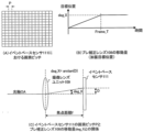
- Figures 4(A) to (C) are explanatory diagrams of the amount of movement of the motion compensation lens 108.
- FIG. 4A the grid represents pixels arranged in an array in the event-based sensor 111.
- the pixels are arranged at the positions where the horizontal and vertical lines intersect, and the distance P corresponds to the pixel pitch.
- FIG. 4B is an explanatory diagram of the movement amount (vibration target position) of the motion compensation lens 108.
- the horizontal axis represents time
- the vertical axis represents the target position.
- the movement amount of the motion compensation lens 108 is defined as the amount of deflection of the optical axis OA, that is, the angle, and is expressed in deg_X as shown in FIG. 4B.
- Frame_T in FIG. 4B is the exposure time of one frame in the imaging device 100.
- the motion compensation lens 108 is moved by an angle deg_X within the exposure time of one frame.
- the objective here is to generate an image in which one frame's worth of luminance changes are accumulated, as in image 31. Therefore, the movement of the motion compensation lens 108 can achieve its purpose as long as it is completed within the time frame of Frame_T, and the movement may be completed in a time shorter than Frame_T.
- imaging lens unit 109 includes blur correction lens 108, but for ease of explanation, it is illustrated in a simplified manner.
- blur correction lens 108 is not moving, optical axis OA passing through imaging lens unit 109 passes through approximately the center of event-based sensor 111.
- optical axis OA becomes tilted by angle deg_X.
- the imaging position of the subject image on event-based sensor 111 changes.
- the amount of change in imaging position is taken as D.
- the focal length f of the imaging lens unit 109 is in the same units as the amount of change D, for example, millimeters.
- the angle deg_X can generally be expressed by the formula arctan(D/f).
- the amount of change D in the imaging position on the event-based sensor 111 must be greater than the distance P between pixels (pixel pitch).
- Figure 5 (A) shows the imaging range before the motion compensation lens 108 is moved.
- the black area within the imaging range becomes larger.
- the motion compensation lens 108 has not moved before the image of FIG. 5(A) is captured, and if there is no change in the brightness on the chart, the event-based sensor 111 does not issue any event, and the image shown in FIG. 5(E) is obtained.
- this is an image in which the areas where no events have occurred are represented in gray, and other color schemes may be used.
- the black part of the chart becomes the captured area after the motion compensation lens 108 is moved. Since the brightness of this area decreases due to the movement of the motion compensation lens 108, it becomes black, indicating a negative event, as shown in FIG. 5(F).
- an event can be forcibly issued by slightly shifting the imaging position of the subject image using the image blur correction lens 108.
- a mechanism may be used in which an actuator is mounted on event-based sensor 111 (the stage that holds event-based sensor 111) to enable the stage itself to be moved.
- a pan-tilt mechanism may be used that can rotate a camera section (imaging section) that integrates imaging lens unit 109 and event-based sensor 111 up, down, left and right.
- these shake correction mechanisms are driven by a fixed amount to change the imaging position of the subject image and issue an event.
- an event may be issued by adjusting the amount of light passing through imaging lens unit 109 to change the brightness value detected by each pixel of event-based sensor 111.
- a mechanism that changes the amount of light (brightness), such as a diaphragm (aperture diaphragm) or a neutral density filter in imaging lens unit 109, may be used.
- an event may be issued by moving the zoom lens or focus lens that constitutes the imaging lens unit 109 a small amount in the optical axis direction to change the angle of view.
- a mechanism solely for issuing an event may also be provided.
- a vibration generating member may be provided between an imaging unit that integrates imaging lens unit 109 and event-based sensor 111, and a fixed part on which the imaging device is mounted. In this case, when the event issuing mode is selected, an event may be issued by changing the positional relationship between the imaging unit and the subject using the vibration generating member.
- the driving unit can drive at least one of the optical members constituting at least a part of the imaging lens unit 109 and the event-based sensor 111 so that the change in luminance exceeds a predetermined threshold. Therefore, according to this embodiment, the user can generate an event image at a desired timing, and can perform work such as setting up the imaging device (image processing device) while checking the event image.
- FIG. 6 is a block diagram of the imaging device 200.
- the imaging device 200 has an event-based sensor 111, similar to the imaging device 100 described with reference to Fig. 1. Furthermore, in addition to the components of the imaging device 100, the imaging device 200 has an autofocus function.
- the imaging lens 201 has at least the motion compensation lens 108 and a focus lens 202.
- the focus lens 202 is a focus compensator lens that moves in the optical axis direction.
- the focus signal processing unit 203 generates a focus signal based on the event image output from the data processing unit 112.
- the focus signal is a value indicating the sharpness (contrast state) of the image, and represents the focus state of the imaging optical system. When the focus state is in focus, the sharpness is high. On the other hand, when the focus state is blurred (out of focus), the sharpness is low. In this way, the focus signal can be used as a value indicating the focus state of the imaging optical system.
- the focus signal processing unit 203 generates signals such as a luminance difference signal (the difference between the maximum and minimum luminance levels of the area used for focus detection).
- the event-based sensor 111 since the event-based sensor 111 does not have a mechanism for detecting absolute luminance information, it is preferable to provide a sensor capable of detecting luminance (not shown) separately from the event-based sensor 111.
- the focus lens control unit 204 drives the focus lens 202 based on the output signal of the focus signal processing unit 203.
- Figures 7(A) and (B) are explanatory diagrams of the change in focus signal (focus determination method) according to the focus lens position for a specified subject.
- the autofocus function moves the focus lens position while checking the focus signal value, and searches for the position where the focus signal value is largest.
- an index called a simple focus degree may be used to switch the control of the focus lens 202. For example, if the determination using the simple focus degree indicates that the focus lens 202 is not in focus, the movement speed of the focus lens 202 is increased to quickly reach the vicinity of the in-focus point. On the other hand, in an area where the simple focus degree indicates that the focus lens 202 is in focus, the movement speed of the focus lens 202 is slowed down to perform a detailed search.
- the focus signal TEP is a value obtained by extracting high-frequency components from the video signal. Using the difference MMP between the maximum and minimum brightness levels of the area used for focus detection, the simple focus degree can be calculated by dividing the focus signal TEP by the difference MMP.
- the dotted line 702 in Figs. 7A and 7B shows the concept of how the differential MMP changes depending on the focus lens position.
- the dotted line 702 has a smaller increase or decrease in value depending on the focus lens position compared to the focus signal described above. This is because the maximum and minimum values of the brightness level are approximately the same regardless of the blur state as long as the subject is the same, and the fluctuation of the focus signal due to the subject can be suppressed to a certain extent. Therefore, in this embodiment, when the value of the simple focus degree (TEP/MM) is 55% or more (area 703), it is determined that the focus state is in focus.
- the ratio (determination value) of the simple focus degree is not limited to the above ratio.
- the motion compensation lens 108 is moved to issue an event from the event-based sensor 111, the sharpness of the event image decreases.
- the motion compensation lens 108 is moved by the pixel pitch, that is, to change the imaging position by one pixel, resulting in a state in which one pixel of subject blur occurs.
- the maximum and minimum values of the luminance level can be considered to be approximately the same even if the blur state changes, so the maximum and minimum values of the luminance level do not change even if the motion compensation lens 108 is moved. This is as shown in the graphs of the solid line 701 and the dotted line 702 in Figures 7(A) and (B). In other words, the simple focus degree calculated from the image acquired with the motion compensation lens 108 moved is lower in value than the simple focus degree calculated from the image acquired with the motion compensation lens 108 not moved.
- the judgment threshold value in consideration of the fact that the simple focusing degree in the event issuance mode in which an event image is issued by moving the motion compensation lens 108 will be a lower value than the original numerical value.
- the simple focusing degree is X1 % or more (area 703), it is judged to be in focus, and if it is less than X2 % (area 705), it is judged to be in a highly blurred state, satisfying 55 ⁇ X1 and 40 ⁇ X2 .
- the judgment value (ratio) only indicates that the threshold value used for judgment based on the simple focusing degree in the event issuing mode is lower than the threshold value used in an imaging device equipped with a normal CMOS imaging sensor, and is not limited to the value given in this embodiment.
- X1 and X2 may be measured to measure the degree of decrease in the simple focusing degree relative to the movement amount of the motion compensation lens 108, and stored in advance as table data.
- the focus signal processing unit 203 obtains the movement amount of the motion compensation lens 108 from the fixed movement amount calculation unit 114, and obtains X1 and X2 corresponding to the obtained movement amount from the table. Then, the focus signal processing unit 203 uses the obtained X1 and X2 for judgment based on the simple focusing degree, making it possible to make an appropriate judgment even when the motion compensation lens 108 is moving.
- the object driven by the drive unit is not limited to the motion compensation lens 108, as in the first embodiment, but may be a mechanism for moving a stage on which the event-based sensor 111 is mounted, a variable angle prism, a pan-tilt mechanism, or the like.
- the imaging device is described as a digital camera, but is not limited thereto.
- Each embodiment can be applied to other devices accompanied by an event-driven vision sensor. That is, each embodiment can be applied to a mobile phone terminal, a portable image viewer, a television equipped with a camera, a digital photo frame, a music player, a game machine, an electronic book reader, an industrial device, a measuring device, and the like.
- each embodiment is not limited to the imaging device, and can be applied to an image processing device that does not have an imaging function but has a function of playing moving images.
- the present invention can also be realized by a process in which a program for implementing one or more of the functions of the above-described embodiments is supplied to a system or device via a network or a storage medium, and one or more processors in a computer of the system or device read and execute the program.
- the present invention can also be realized by a circuit (e.g., ASIC) that implements one or more of the functions.
- an image processing device an imaging device, an image processing method, and a program that allow a user to check an image at a desired timing.
Landscapes
- Engineering & Computer Science (AREA)
- Multimedia (AREA)
- Signal Processing (AREA)
- Physics & Mathematics (AREA)
- General Physics & Mathematics (AREA)
- Optics & Photonics (AREA)
- Computer Vision & Pattern Recognition (AREA)
- Computing Systems (AREA)
- Theoretical Computer Science (AREA)
- Studio Devices (AREA)
- Transforming Light Signals Into Electric Signals (AREA)
- Automatic Focus Adjustment (AREA)
- Adjustment Of Camera Lenses (AREA)
Priority Applications (1)
| Application Number | Priority Date | Filing Date | Title |
|---|---|---|---|
| US19/089,359 US20250227385A1 (en) | 2022-10-25 | 2025-03-25 | Image processing apparatus, image pickup apparatus, image processing method, and storage medium |
Applications Claiming Priority (2)
| Application Number | Priority Date | Filing Date | Title |
|---|---|---|---|
| JP2022170958A JP2024062847A (ja) | 2022-10-25 | 2022-10-25 | 画像処理装置、撮像装置、画像処理方法、およびプログラム |
| JP2022-170958 | 2022-10-25 |
Related Child Applications (1)
| Application Number | Title | Priority Date | Filing Date |
|---|---|---|---|
| US19/089,359 Continuation US20250227385A1 (en) | 2022-10-25 | 2025-03-25 | Image processing apparatus, image pickup apparatus, image processing method, and storage medium |
Publications (1)
| Publication Number | Publication Date |
|---|---|
| WO2024089968A1 true WO2024089968A1 (ja) | 2024-05-02 |
Family
ID=90830480
Family Applications (1)
| Application Number | Title | Priority Date | Filing Date |
|---|---|---|---|
| PCT/JP2023/028690 Ceased WO2024089968A1 (ja) | 2022-10-25 | 2023-08-07 | 画像処理装置、撮像装置、画像処理方法、およびプログラム |
Country Status (3)
| Country | Link |
|---|---|
| US (1) | US20250227385A1 (https=) |
| JP (1) | JP2024062847A (https=) |
| WO (1) | WO2024089968A1 (https=) |
Families Citing this family (1)
| Publication number | Priority date | Publication date | Assignee | Title |
|---|---|---|---|---|
| JP7672752B1 (ja) * | 2024-04-09 | 2025-05-08 | TwinSense株式会社 | 情報処理装置、システム及び方法 |
Citations (3)
| Publication number | Priority date | Publication date | Assignee | Title |
|---|---|---|---|---|
| WO2020071267A1 (ja) * | 2018-10-04 | 2020-04-09 | 株式会社ソニー・インタラクティブエンタテインメント | センサモジュール、電子機器、ビジョンセンサの校正方法、被写体の検出方法およびプログラム |
| JP2021067704A (ja) * | 2019-10-17 | 2021-04-30 | 株式会社デンソーウェーブ | 撮像装置 |
| WO2022190598A1 (ja) * | 2021-03-09 | 2022-09-15 | ソニーグループ株式会社 | 情報処理装置と情報処理方法とプログラムおよび撮像システム |
-
2022
- 2022-10-25 JP JP2022170958A patent/JP2024062847A/ja active Pending
-
2023
- 2023-08-07 WO PCT/JP2023/028690 patent/WO2024089968A1/ja not_active Ceased
-
2025
- 2025-03-25 US US19/089,359 patent/US20250227385A1/en active Pending
Patent Citations (3)
| Publication number | Priority date | Publication date | Assignee | Title |
|---|---|---|---|---|
| WO2020071267A1 (ja) * | 2018-10-04 | 2020-04-09 | 株式会社ソニー・インタラクティブエンタテインメント | センサモジュール、電子機器、ビジョンセンサの校正方法、被写体の検出方法およびプログラム |
| JP2021067704A (ja) * | 2019-10-17 | 2021-04-30 | 株式会社デンソーウェーブ | 撮像装置 |
| WO2022190598A1 (ja) * | 2021-03-09 | 2022-09-15 | ソニーグループ株式会社 | 情報処理装置と情報処理方法とプログラムおよび撮像システム |
Also Published As
| Publication number | Publication date |
|---|---|
| JP2024062847A (ja) | 2024-05-10 |
| US20250227385A1 (en) | 2025-07-10 |
Similar Documents
| Publication | Publication Date | Title |
|---|---|---|
| JP4235474B2 (ja) | 撮像装置 | |
| US8135268B2 (en) | Lens control apparatus, optical apparatus and lens control method | |
| JP3530696B2 (ja) | 撮像装置 | |
| JP2008172667A (ja) | 撮像装置 | |
| US11272109B2 (en) | Blur correction control apparatus, method, and storage medium | |
| JP2013038482A (ja) | 撮像装置 | |
| US11092774B2 (en) | Lens apparatus, image capturing apparatus, control method of lens apparatus, and control method of image capturing apparatus | |
| US9742983B2 (en) | Image capturing apparatus with automatic focus adjustment and control method thereof, and storage medium | |
| US20250227385A1 (en) | Image processing apparatus, image pickup apparatus, image processing method, and storage medium | |
| JP7341844B2 (ja) | レンズ制御装置、光学機器およびレンズ制御方法 | |
| JP3754964B2 (ja) | 撮像装置 | |
| JP4508991B2 (ja) | 撮像装置 | |
| US11218637B2 (en) | Image capture apparatus and control method having image stabilization which reduces peripheral light variation | |
| JP6348223B2 (ja) | 測距装置、測距用制御方法、及び測距用制御プログラム | |
| US20190297269A1 (en) | Control apparatus, imaging apparatus, and control method | |
| JP4612814B2 (ja) | 自動焦点調節装置及びその制御方法並びに撮像装置 | |
| US20150168739A1 (en) | Image stabilizer, camera system, and imaging method | |
| JP6348222B2 (ja) | 測距装置、測距用制御方法、及び測距用制御プログラム | |
| JP2008129255A (ja) | 撮像装置、撮像方法、およびプログラム | |
| JP4898151B2 (ja) | 撮像装置及び撮像方法 | |
| JP5665402B2 (ja) | 撮像システム及びその制御方法 | |
| JP2011135537A (ja) | 撮像装置及び撮像装置の制御方法 | |
| JP2005311972A (ja) | 撮像装置、および制御方法 | |
| JPH0815598A (ja) | リアーフォーカス式ズームレンズのピント調節方法 | |
| JP6348221B2 (ja) | 測距装置、測距用制御方法、及び測距用制御プログラム |
Legal Events
| Date | Code | Title | Description |
|---|---|---|---|
| 121 | Ep: the epo has been informed by wipo that ep was designated in this application |
Ref document number: 23882184 Country of ref document: EP Kind code of ref document: A1 |
|
| NENP | Non-entry into the national phase |
Ref country code: DE |
|
| 122 | Ep: pct application non-entry in european phase |
Ref document number: 23882184 Country of ref document: EP Kind code of ref document: A1 |