WO2024089968A1 - 画像処理装置、撮像装置、画像処理方法、およびプログラム - Google Patents
画像処理装置、撮像装置、画像処理方法、およびプログラム Download PDFInfo
- Publication number
- WO2024089968A1 WO2024089968A1 PCT/JP2023/028690 JP2023028690W WO2024089968A1 WO 2024089968 A1 WO2024089968 A1 WO 2024089968A1 JP 2023028690 W JP2023028690 W JP 2023028690W WO 2024089968 A1 WO2024089968 A1 WO 2024089968A1
- Authority
- WO
- WIPO (PCT)
- Prior art keywords
- event
- image
- imaging
- image processing
- optical member
- Prior art date
Links
- 238000003384 imaging method Methods 0.000 title claims abstract description 93
- 238000012545 processing Methods 0.000 title claims abstract description 40
- 238000003672 processing method Methods 0.000 title claims description 4
- 230000003287 optical effect Effects 0.000 claims abstract description 52
- 238000000034 method Methods 0.000 claims abstract description 12
- 230000008569 process Effects 0.000 claims abstract description 6
- 230000008859 change Effects 0.000 claims description 47
- 238000001514 detection method Methods 0.000 claims description 12
- 230000007935 neutral effect Effects 0.000 claims description 2
- 238000012937 correction Methods 0.000 description 23
- 230000007246 mechanism Effects 0.000 description 14
- 238000010586 diagram Methods 0.000 description 13
- 230000006641 stabilisation Effects 0.000 description 7
- 238000011105 stabilization Methods 0.000 description 7
- 230000007423 decrease Effects 0.000 description 5
- 238000006243 chemical reaction Methods 0.000 description 2
- 230000003068 static effect Effects 0.000 description 2
- 230000003321 amplification Effects 0.000 description 1
- 239000003086 colorant Substances 0.000 description 1
- 238000012790 confirmation Methods 0.000 description 1
- 238000006073 displacement reaction Methods 0.000 description 1
- 230000004907 flux Effects 0.000 description 1
- 239000007788 liquid Substances 0.000 description 1
- 238000012986 modification Methods 0.000 description 1
- 230000004048 modification Effects 0.000 description 1
- 238000003199 nucleic acid amplification method Methods 0.000 description 1
- 238000012805 post-processing Methods 0.000 description 1
- 230000009467 reduction Effects 0.000 description 1
- 229920006395 saturated elastomer Polymers 0.000 description 1
- 230000000007 visual effect Effects 0.000 description 1
Images


Classifications
-
- G—PHYSICS
- G02—OPTICS
- G02B—OPTICAL ELEMENTS, SYSTEMS OR APPARATUS
- G02B7/00—Mountings, adjusting means, or light-tight connections, for optical elements
- G02B7/28—Systems for automatic generation of focusing signals
- G02B7/36—Systems for automatic generation of focusing signals using image sharpness techniques, e.g. image processing techniques for generating autofocus signals
-
- G—PHYSICS
- G03—PHOTOGRAPHY; CINEMATOGRAPHY; ANALOGOUS TECHNIQUES USING WAVES OTHER THAN OPTICAL WAVES; ELECTROGRAPHY; HOLOGRAPHY
- G03B—APPARATUS OR ARRANGEMENTS FOR TAKING PHOTOGRAPHS OR FOR PROJECTING OR VIEWING THEM; APPARATUS OR ARRANGEMENTS EMPLOYING ANALOGOUS TECHNIQUES USING WAVES OTHER THAN OPTICAL WAVES; ACCESSORIES THEREFOR
- G03B5/00—Adjustment of optical system relative to image or object surface other than for focusing
-
- H—ELECTRICITY
- H04—ELECTRIC COMMUNICATION TECHNIQUE
- H04N—PICTORIAL COMMUNICATION, e.g. TELEVISION
- H04N23/00—Cameras or camera modules comprising electronic image sensors; Control thereof
- H04N23/50—Constructional details
- H04N23/54—Mounting of pick-up tubes, electronic image sensors, deviation or focusing coils
-
- H—ELECTRICITY
- H04—ELECTRIC COMMUNICATION TECHNIQUE
- H04N—PICTORIAL COMMUNICATION, e.g. TELEVISION
- H04N23/00—Cameras or camera modules comprising electronic image sensors; Control thereof
- H04N23/50—Constructional details
- H04N23/55—Optical parts specially adapted for electronic image sensors; Mounting thereof
-
- H—ELECTRICITY
- H04—ELECTRIC COMMUNICATION TECHNIQUE
- H04N—PICTORIAL COMMUNICATION, e.g. TELEVISION
- H04N23/00—Cameras or camera modules comprising electronic image sensors; Control thereof
- H04N23/58—Means for changing the camera field of view without moving the camera body, e.g. nutating or panning of optics or image sensors
-
- H—ELECTRICITY
- H04—ELECTRIC COMMUNICATION TECHNIQUE
- H04N—PICTORIAL COMMUNICATION, e.g. TELEVISION
- H04N23/00—Cameras or camera modules comprising electronic image sensors; Control thereof
- H04N23/60—Control of cameras or camera modules
-
- H—ELECTRICITY
- H04—ELECTRIC COMMUNICATION TECHNIQUE
- H04N—PICTORIAL COMMUNICATION, e.g. TELEVISION
- H04N23/00—Cameras or camera modules comprising electronic image sensors; Control thereof
- H04N23/95—Computational photography systems, e.g. light-field imaging systems
-
- H—ELECTRICITY
- H04—ELECTRIC COMMUNICATION TECHNIQUE
- H04N—PICTORIAL COMMUNICATION, e.g. TELEVISION
- H04N25/00—Circuitry of solid-state image sensors [SSIS]; Control thereof
- H04N25/47—Image sensors with pixel address output; Event-driven image sensors; Selection of pixels to be read out based on image data
-
- H—ELECTRICITY
- H04—ELECTRIC COMMUNICATION TECHNIQUE
- H04N—PICTORIAL COMMUNICATION, e.g. TELEVISION
- H04N25/00—Circuitry of solid-state image sensors [SSIS]; Control thereof
- H04N25/70—SSIS architectures; Circuits associated therewith
- H04N25/76—Addressed sensors, e.g. MOS or CMOS sensors
- H04N25/78—Readout circuits for addressed sensors, e.g. output amplifiers or A/D converters
Definitions
- the present invention relates to an image processing device, an imaging device, an image processing method, and a program.
- an event-based sensor detects the occurrence of an event based on the luminance change of each pixel, and asynchronously outputs an event signal that includes the time when the event occurred and the pixel position. In this way, an event-based sensor can detect the occurrence of an event when the luminance change exceeds a predetermined threshold, and has low latency and low calculation costs compared to reading out pixel signals from all pixels.
- event-based sensors convert brightness into a voltage logarithmically, so while they can detect slight differences in brightness when the brightness is low, they react to large differences in brightness when the brightness is high, preventing events from becoming saturated and providing a wide dynamic range.
- Event-based sensors also have a high time resolution for event information, ranging from a few nanoseconds to a few microseconds, and subject blurring is minimal when dealing with moving subjects.
- Patent Document 1 discloses an event camera that generates images (frame data) from event signals output from an event-based sensor.
- the present invention aims to provide an image processing device that allows the user to check images at any time.
- An image processing device has an imaging sensor that detects the occurrence of an event when a luminance change for each pixel exceeds a predetermined threshold and outputs an event signal including information about the time the event occurred and the pixel position at which the event occurred, a drive unit that drives at least one of the imaging sensor or an optical member that constitutes at least a part of the imaging optical system so that the luminance change exceeds the predetermined threshold, and a processing unit that processes the event signal output from the imaging sensor while the drive unit drives at least one of the optical member or the imaging sensor.
- the present invention provides an image processing device that allows a user to check an image at a desired time.
- FIG. 1 is a block diagram of an imaging apparatus according to a first embodiment.
- FIG. 2 is an explanatory diagram of an event generated by an event-based sensor in the first embodiment.
- 4 is an example of an event image according to the first embodiment.
- 5 is an explanatory diagram of the movement amount of the motion compensation lens in the first embodiment.
- FIG. FIG. 4 is an explanatory diagram of an event image in the first embodiment.
- FIG. 11 is a block diagram of an imaging apparatus according to a second embodiment. 13 is an explanatory diagram of a method of focus determination in the second embodiment.
- FIG. 1 is a block diagram of the image capturing apparatus 100.
- the image capturing apparatus 100 has an event-based sensor (image capturing sensor) 111.
- the image capturing apparatus 100 also has an optical image stabilization mechanism.
- the imaging device 100 has at least two modes for switching the use of the optical image stabilization mechanism.
- One of the two modes is a stabilization mode (second mode) in which the stabilization mechanism is driven based on vibrations applied to the imaging device 100.
- the other is an event issuing mode (first mode) in which the stabilization lens (optical member) 108 is driven to issue an event (output an event signal) from the event-based sensor 111. Details will be described later, but in the event issuing mode, the stabilization lens 108 is minutely driven regardless of the vibrations applied to the imaging device 100. This changes the imaging position of the subject image on the event-based sensor 111, forcibly causing a change in brightness for each pixel in the event-based sensor 111.
- the vibration applied to the imaging device is referred to as "vibration”
- the displacement of the subject position between frames of an imaged image caused by the vibration applied to the imaging device, or the blurring of the subject image is referred to as "shake”.
- Event-based sensor 111 detects the luminance change of each pixel within the imaging range and outputs an event signal asynchronously.
- Event-based sensor 111 is configured, for example, by arranging multiple pixels in an array, and when a change in a voltage signal (luminance change) that is the logarithm of the intensity of light incident on each pixel exceeds a predetermined threshold, a trigger signal is generated and output as an event signal.
- the event signal is a signal associated with an event. For example, it includes the time when the occurrence of the event was detected (occurrence time) and the pixel position where the event occurred. The time when the occurrence of the event was detected may be measured based on the internal clock of event-based sensor 111 (the time of event-based sensor 111), or may be reset as necessary.
- the event signal includes information about the time the event occurred and the pixel position where the event occurred, and may further include information about a change in luminance.
- the information about the change in luminance may be the amount of change in luminance itself, or information indicating whether the luminance change is positive or negative.
- the event-based sensor 111 asynchronously outputs the event signal only when a change in luminance occurs (when the change in luminance exceeds a predetermined threshold).
- "outputting the event signal asynchronously” means that the event signal is output independently in time on a pixel-by-pixel basis, without synchronization across all pixels of the event-based sensor 111.
- FIG. 2 is an explanatory diagram of an event generated by the event-based sensor 111.
- the horizontal axis indicates time t
- the vertical axis indicates voltage V P , which is the logarithm of the intensity of light incident on the event-based sensor 111.
- a dotted line drawn horizontally from the voltage V P is a threshold (predetermined threshold) of the voltage signal at which the event-based sensor 111 generates a trigger signal, and is set in units of the amount of change in voltage (threshold ⁇ ).
- the lower diagram in FIG. 2 shows the detection timing of an event.
- data processing unit 112 receives an event signal output from event-based sensor 111, processes the received event signal, and generates image data (event image) from the event signal.
- data processing unit 112 processes the event signal output from event-based sensor 111 while the driving unit drives blur correction lens 108, as described below.
- FIG. 3 shows an example of an event image generated based on an event signal output from event-based sensor 111.
- Image 30 is an image captured by a general imaging device equipped with an imaging element such as a CMOS image sensor or a CCD image sensor. Image 30 includes detailed data even for static background parts with no change in luminance.
- image 31 is an event image (framed event image) generated as one frame from multiple events that occurred during a period equivalent to the period during which a general imaging element such as a CMOS image sensor accumulates light to generate image 30.
- black areas black pixels
- white areas white pixels
- Gray areas are pixel areas where no events have occurred.
- the outline of the area where a person is moving is made up of black or white pixels, and the movement of the person can be recognized by detecting the change in luminance.
- static background parts (such as a pedestrian crossing) are gray areas because there is no change in luminance. Note that the method of expressing the black, white, and gray areas is not limited to the above example, and other colors may be used, and the pixel values may be changed according to the intensity level of the luminance change.
- image 31 contains significantly less data per given time period than image 30, making post-processing to track or recognize changes in a scene easier and more efficient.
- Image 31 generated by data processing unit 112 can be displayed on an output device (not shown) for visual confirmation by a user, or image 31 may be recorded on a recording medium (not shown) in conjunction with the occurrence of an event.
- the shake detection sensor 101 is a sensor that detects shake applied to the imaging device 100, and is, for example, an angular velocity sensor that detects the angular velocity generated in the imaging device 100.
- the shake correction amount calculation unit 102 calculates the target position (movement target position) of the shake correction lens 108 based on the output signal of the shake detection sensor 101.
- the shake correction amount calculation unit 102 has, for example, an HPF (high pass filter) for removing unnecessary offset output from the output signal of the angular velocity sensor.
- the shake correction amount calculation unit 102 also has, for example, an integrator for converting angular velocity shake data into angles, a unit conversion unit for converting angle data into units of position information of the shake correction lens 108, and a phase compensation filter for compensating for the phase delay of the shake detection sensor 101 itself.
- the shake correction lens movement amount selection unit 103 selects an appropriate target position of the shake correction lens 108 according to the current mode based on the target position calculated by the shake correction amount calculation unit 102 and a vibration target position described later.
- the mode is one of at least two modes: the blur correction mode and the event issuing mode mentioned above.
- the motion compensation lens 108 is driven by feedback control based on the difference data between the signal indicating the target position and the output signal of the position detection sensor 110.
- the difference data obtained by subtracting the output signal of the position detection sensor 110 from the signal indicating the target position is output to the control filter 104.
- the control filter 104 performs signal processing such as amplification and phase compensation on the difference data.
- the pulse width modulation unit 105 modulates the output data of the control filter 104 into a waveform that changes the duty ratio of the pulse wave, i.e., a PWM waveform.
- the motor driving unit 106 is a circuit that applies a driving signal to the motor 107.
- the motor driving unit 106 is an H-bridge circuit, and the motor 107 is a voice coil type motor, but this is not limited to these examples.
- the motor driving unit 106 and the motor 107 constitute a driving unit that drives the blur correction lens 108 so that the luminance change exceeds a predetermined threshold value.
- the imaging lens unit (imaging optical system) 109 has a motion compensation lens 108 and forms a subject image on the event-based sensor 111.
- the imaging lens unit 109 includes, for example, at least one of a zoom lens or a focus lens, but is not limited to these.
- the motion compensation lens 108 is, for example, a shift lens, and is capable of deflecting the optical axis OA by moving in a direction different from the direction along the optical axis OA (optical axis direction).
- the motion compensation lens 108 is not limited to a shift lens, and other optical components may be used as long as they are capable of deflecting the optical axis OA, such as a mechanism (variable angle prism) that injects liquid between the lenses to change the shape of the lenses themselves to deflect the optical axis OA.
- the motion compensation lens 108 By moving the motion compensation lens 108 in accordance with the shake of the imaging device 100, the change in the imaging position of the subject caused by the shake of the imaging device 100 can be canceled out by deflecting the optical axis OA, and the imaging position of the subject image can be kept at a specified position.
- the position detection sensor 110 has a magnet and a Hall sensor.
- the positional relationship between the magnet and the Hall sensor changes as the motion compensation lens 108 moves, and the magnetic flux density received by the Hall sensor changes, causing the output of the Hall sensor to change.
- the event issuing mode setting unit (setting unit) 113 notifies the fixed movement amount calculation unit 114 that the current mode is the event issuing mode (first mode).
- the event issuing mode can be selected and set by the user performing a menu operation.
- the event issuing mode setting unit 113 can set, for example, the event issuing mode (first mode) or the blur correction mode (second mode).
- the event issuing mode setting unit 113 may be configured to automatically set the event issuing mode when the imaging device 100 is started up or initially set. If the event mode is not selected, as described above, the blur correction mode (second mode) in which the blur correction lens 108 is moved based on the shake of the imaging device 100 is selected. However, even if the event issuing mode is not selected, the user can select to enable or disable blur correction.
- Fixed movement amount calculation unit 114 outputs a fixed movement amount unrelated to the shake of imaging device 100 as the movement amount of motion compensation lens 108.
- motion compensation lens 108 moves by the fixed movement amount
- the imaging position of the subject image changes by a greater amount than the distance between pixels (pixel pitch) of event-based sensor 111.
- each pixel detects a luminance change, and an event is issued (detected).
- the movement target position of motion compensation lens 108 at this time is set as the vibration target position.
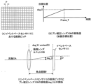
- Figures 4(A) to (C) are explanatory diagrams of the amount of movement of the motion compensation lens 108.
- FIG. 4A the grid represents pixels arranged in an array in the event-based sensor 111.
- the pixels are arranged at the positions where the horizontal and vertical lines intersect, and the distance P corresponds to the pixel pitch.
- FIG. 4B is an explanatory diagram of the movement amount (vibration target position) of the motion compensation lens 108.
- the horizontal axis represents time
- the vertical axis represents the target position.
- the movement amount of the motion compensation lens 108 is defined as the amount of deflection of the optical axis OA, that is, the angle, and is expressed in deg_X as shown in FIG. 4B.
- Frame_T in FIG. 4B is the exposure time of one frame in the imaging device 100.
- the motion compensation lens 108 is moved by an angle deg_X within the exposure time of one frame.
- the objective here is to generate an image in which one frame's worth of luminance changes are accumulated, as in image 31. Therefore, the movement of the motion compensation lens 108 can achieve its purpose as long as it is completed within the time frame of Frame_T, and the movement may be completed in a time shorter than Frame_T.
- imaging lens unit 109 includes blur correction lens 108, but for ease of explanation, it is illustrated in a simplified manner.
- blur correction lens 108 is not moving, optical axis OA passing through imaging lens unit 109 passes through approximately the center of event-based sensor 111.
- optical axis OA becomes tilted by angle deg_X.
- the imaging position of the subject image on event-based sensor 111 changes.
- the amount of change in imaging position is taken as D.
- the focal length f of the imaging lens unit 109 is in the same units as the amount of change D, for example, millimeters.
- the angle deg_X can generally be expressed by the formula arctan(D/f).
- the amount of change D in the imaging position on the event-based sensor 111 must be greater than the distance P between pixels (pixel pitch).
- Figure 5 (A) shows the imaging range before the motion compensation lens 108 is moved.
- the black area within the imaging range becomes larger.
- the motion compensation lens 108 has not moved before the image of FIG. 5(A) is captured, and if there is no change in the brightness on the chart, the event-based sensor 111 does not issue any event, and the image shown in FIG. 5(E) is obtained.
- this is an image in which the areas where no events have occurred are represented in gray, and other color schemes may be used.
- the black part of the chart becomes the captured area after the motion compensation lens 108 is moved. Since the brightness of this area decreases due to the movement of the motion compensation lens 108, it becomes black, indicating a negative event, as shown in FIG. 5(F).
- an event can be forcibly issued by slightly shifting the imaging position of the subject image using the image blur correction lens 108.
- a mechanism may be used in which an actuator is mounted on event-based sensor 111 (the stage that holds event-based sensor 111) to enable the stage itself to be moved.
- a pan-tilt mechanism may be used that can rotate a camera section (imaging section) that integrates imaging lens unit 109 and event-based sensor 111 up, down, left and right.
- these shake correction mechanisms are driven by a fixed amount to change the imaging position of the subject image and issue an event.
- an event may be issued by adjusting the amount of light passing through imaging lens unit 109 to change the brightness value detected by each pixel of event-based sensor 111.
- a mechanism that changes the amount of light (brightness), such as a diaphragm (aperture diaphragm) or a neutral density filter in imaging lens unit 109, may be used.
- an event may be issued by moving the zoom lens or focus lens that constitutes the imaging lens unit 109 a small amount in the optical axis direction to change the angle of view.
- a mechanism solely for issuing an event may also be provided.
- a vibration generating member may be provided between an imaging unit that integrates imaging lens unit 109 and event-based sensor 111, and a fixed part on which the imaging device is mounted. In this case, when the event issuing mode is selected, an event may be issued by changing the positional relationship between the imaging unit and the subject using the vibration generating member.
- the driving unit can drive at least one of the optical members constituting at least a part of the imaging lens unit 109 and the event-based sensor 111 so that the change in luminance exceeds a predetermined threshold. Therefore, according to this embodiment, the user can generate an event image at a desired timing, and can perform work such as setting up the imaging device (image processing device) while checking the event image.
- FIG. 6 is a block diagram of the imaging device 200.
- the imaging device 200 has an event-based sensor 111, similar to the imaging device 100 described with reference to Fig. 1. Furthermore, in addition to the components of the imaging device 100, the imaging device 200 has an autofocus function.
- the imaging lens 201 has at least the motion compensation lens 108 and a focus lens 202.
- the focus lens 202 is a focus compensator lens that moves in the optical axis direction.
- the focus signal processing unit 203 generates a focus signal based on the event image output from the data processing unit 112.
- the focus signal is a value indicating the sharpness (contrast state) of the image, and represents the focus state of the imaging optical system. When the focus state is in focus, the sharpness is high. On the other hand, when the focus state is blurred (out of focus), the sharpness is low. In this way, the focus signal can be used as a value indicating the focus state of the imaging optical system.
- the focus signal processing unit 203 generates signals such as a luminance difference signal (the difference between the maximum and minimum luminance levels of the area used for focus detection).
- the event-based sensor 111 since the event-based sensor 111 does not have a mechanism for detecting absolute luminance information, it is preferable to provide a sensor capable of detecting luminance (not shown) separately from the event-based sensor 111.
- the focus lens control unit 204 drives the focus lens 202 based on the output signal of the focus signal processing unit 203.
- Figures 7(A) and (B) are explanatory diagrams of the change in focus signal (focus determination method) according to the focus lens position for a specified subject.
- the autofocus function moves the focus lens position while checking the focus signal value, and searches for the position where the focus signal value is largest.
- an index called a simple focus degree may be used to switch the control of the focus lens 202. For example, if the determination using the simple focus degree indicates that the focus lens 202 is not in focus, the movement speed of the focus lens 202 is increased to quickly reach the vicinity of the in-focus point. On the other hand, in an area where the simple focus degree indicates that the focus lens 202 is in focus, the movement speed of the focus lens 202 is slowed down to perform a detailed search.
- the focus signal TEP is a value obtained by extracting high-frequency components from the video signal. Using the difference MMP between the maximum and minimum brightness levels of the area used for focus detection, the simple focus degree can be calculated by dividing the focus signal TEP by the difference MMP.
- the dotted line 702 in Figs. 7A and 7B shows the concept of how the differential MMP changes depending on the focus lens position.
- the dotted line 702 has a smaller increase or decrease in value depending on the focus lens position compared to the focus signal described above. This is because the maximum and minimum values of the brightness level are approximately the same regardless of the blur state as long as the subject is the same, and the fluctuation of the focus signal due to the subject can be suppressed to a certain extent. Therefore, in this embodiment, when the value of the simple focus degree (TEP/MM) is 55% or more (area 703), it is determined that the focus state is in focus.
- the ratio (determination value) of the simple focus degree is not limited to the above ratio.
- the motion compensation lens 108 is moved to issue an event from the event-based sensor 111, the sharpness of the event image decreases.
- the motion compensation lens 108 is moved by the pixel pitch, that is, to change the imaging position by one pixel, resulting in a state in which one pixel of subject blur occurs.
- the maximum and minimum values of the luminance level can be considered to be approximately the same even if the blur state changes, so the maximum and minimum values of the luminance level do not change even if the motion compensation lens 108 is moved. This is as shown in the graphs of the solid line 701 and the dotted line 702 in Figures 7(A) and (B). In other words, the simple focus degree calculated from the image acquired with the motion compensation lens 108 moved is lower in value than the simple focus degree calculated from the image acquired with the motion compensation lens 108 not moved.
- the judgment threshold value in consideration of the fact that the simple focusing degree in the event issuance mode in which an event image is issued by moving the motion compensation lens 108 will be a lower value than the original numerical value.
- the simple focusing degree is X1 % or more (area 703), it is judged to be in focus, and if it is less than X2 % (area 705), it is judged to be in a highly blurred state, satisfying 55 ⁇ X1 and 40 ⁇ X2 .
- the judgment value (ratio) only indicates that the threshold value used for judgment based on the simple focusing degree in the event issuing mode is lower than the threshold value used in an imaging device equipped with a normal CMOS imaging sensor, and is not limited to the value given in this embodiment.
- X1 and X2 may be measured to measure the degree of decrease in the simple focusing degree relative to the movement amount of the motion compensation lens 108, and stored in advance as table data.
- the focus signal processing unit 203 obtains the movement amount of the motion compensation lens 108 from the fixed movement amount calculation unit 114, and obtains X1 and X2 corresponding to the obtained movement amount from the table. Then, the focus signal processing unit 203 uses the obtained X1 and X2 for judgment based on the simple focusing degree, making it possible to make an appropriate judgment even when the motion compensation lens 108 is moving.
- the object driven by the drive unit is not limited to the motion compensation lens 108, as in the first embodiment, but may be a mechanism for moving a stage on which the event-based sensor 111 is mounted, a variable angle prism, a pan-tilt mechanism, or the like.
- the imaging device is described as a digital camera, but is not limited thereto.
- Each embodiment can be applied to other devices accompanied by an event-driven vision sensor. That is, each embodiment can be applied to a mobile phone terminal, a portable image viewer, a television equipped with a camera, a digital photo frame, a music player, a game machine, an electronic book reader, an industrial device, a measuring device, and the like.
- each embodiment is not limited to the imaging device, and can be applied to an image processing device that does not have an imaging function but has a function of playing moving images.
- the present invention can also be realized by a process in which a program for implementing one or more of the functions of the above-described embodiments is supplied to a system or device via a network or a storage medium, and one or more processors in a computer of the system or device read and execute the program.
- the present invention can also be realized by a circuit (e.g., ASIC) that implements one or more of the functions.
- an image processing device an imaging device, an image processing method, and a program that allow a user to check an image at a desired timing.
Landscapes
- Engineering & Computer Science (AREA)
- Multimedia (AREA)
- Signal Processing (AREA)
- Physics & Mathematics (AREA)
- General Physics & Mathematics (AREA)
- Optics & Photonics (AREA)
- Computer Vision & Pattern Recognition (AREA)
- Computing Systems (AREA)
- Theoretical Computer Science (AREA)
- Studio Devices (AREA)
- Automatic Focus Adjustment (AREA)
- Adjustment Of Camera Lenses (AREA)
- Transforming Light Signals Into Electric Signals (AREA)
Abstract
【課題】所望のタイミングでユーザが画像を確認することが可能な画像処理装置を提供する。 【解決手段】画像処理装置(100)は、画素ごとの輝度変化が所定の閾値を超えた場合に、イベントの発生を検出し、イベントの発生時刻とイベントが発生した画素位置とに関する情報を含むイベント信号を出力する撮像センサ(111)と、輝度変化が所定の閾値を超えるように、撮像光学系(109)の少なくとも一部を構成する光学部材(108)、または撮像センサの少なくとも一方を駆動する駆動部(106、107)と、駆動部が光学部材または撮像センサの少なくとも一方を駆動しながら撮像センサから出力されたイベント信号を処理する処理部(112)とを有する。
Description
本発明は、画像処理装置、撮像装置、画像処理方法、およびプログラムに関する。
従来、イベント駆動型ビジョンセンサ(イベントベースセンサ)を搭載した撮像装置が知られている。イベントベースセンサは、画素ごとの輝度変化に基づいてイベントの発生を検出し、イベントが発生した時刻と画素位置とを含むイベント信号を非同期に出力する。このようにイベントベースセンサは、輝度変化が所定の閾値を超えた場合にイベントの発生を検出することができ、全画素の画素信号を読み出す場合と比べて低レテンシであり計算コストが低い。
またイベントベースセンサは、輝度を電圧へ対数変換するため、輝度の低い状態ではわずかな輝度差の検出が可能である一方、輝度の高い状態では大きな輝度差に対して反応することにより、イベントが飽和する状態を防ぎ、広いダイナミックレンジを有する。またイベントベースセンサは、イベント情報の時間分解能が数ns~数μsと高く、移動被写体に対する被写体ブレが小さい。
特許文献1には、イベントベースセンサから出力されるイベント信号から画像(フレームデータ)を生成するイベントカメラが開示されている。
特許文献1に開示されているイベントカメラでは、輝度変化が発生していない場合には、イベントベースセンサからイベント信号が出力されないため、ユーザは画像を確認することができない。
そこで本発明は、所望のタイミングでユーザが画像を確認することが可能な画像処理装置を提供することを目的とする。
本発明の一側面としての画像処理装置は、画素ごとの輝度変化が所定の閾値を超えた場合に、イベントの発生を検出し、前記イベントの発生時刻と前記イベントが発生した画素位置とに関する情報を含むイベント信号を出力する撮像センサと、前記輝度変化が前記所定の閾値を超えるように、撮像光学系の少なくとも一部を構成する光学部材、または前記撮像センサの少なくとも一方を駆動する駆動部と、前記駆動部が前記光学部材または前記撮像センサの少なくとも一方を駆動しながら前記撮像センサから出力された前記イベント信号を処理する処理部とを有する。
本発明の他の目的及び特徴は、以下の実施形態において説明される。
本発明によれば、所望のタイミングでユーザが画像を確認することが可能な画像処理装置を提供することができる。
以下、本発明の実施形態について、図面を参照しながら詳細に説明する。なお各実施形態には複数の特徴が記載されているが、これらの複数の特徴の全てが本発明に必須であるとは限らず、また、複数の特徴は任意に組み合わせられてもよい。また、図面において、同一若しくは同様の構成に同一の参照番号を付し、重複した説明は省略する。
(第1実施形態)
まず、図1を参照して、本発明の第1実施形態における撮像装置(画像処理装置)100について説明する。図1は、撮像装置100のブロック図である。撮像装置100は、イベントベースセンサ(撮像センサ)111を有する。また撮像装置100は、光学式ブレ補正機構を有する。
まず、図1を参照して、本発明の第1実施形態における撮像装置(画像処理装置)100について説明する。図1は、撮像装置100のブロック図である。撮像装置100は、イベントベースセンサ(撮像センサ)111を有する。また撮像装置100は、光学式ブレ補正機構を有する。
撮像装置100は、光学式ブレ補正機構の用途を切り替える少なくとも2つのモードを有する。2つのモードの1つは、撮像装置100に加わる振動に基づいてブレ補正機構を駆動するブレ補正モード(第2モード)である。他の1つは、イベントベースセンサ111からイベントを発行させる(イベント信号を出力させる)ためにブレ補正レンズ(光学部材)108を駆動するイベント発行モード(第1モード)である。なお、詳細については後述するが、イベント発行モードでは、撮像装置100に加わる振動とは関係なく、ブレ補正レンズ108を微小に駆動させる。これにより、イベントベースセンサ111への被写体像の結像位置を変化させ、イベントベースセンサ111における画素ごとの輝度変化を強制的に生じさせる。なお各実施形態において、撮像装置に加わる振動を「振れ」、撮像装置に加わる振れにより発生する撮像画像のフレーム間の被写体位置ずれ、もしくは被写体像のボケを「ブレ」と記載する。
イベントベースセンサ111は、撮像範囲内における画素ごとの輝度変化を検出し、イベント信号を非同期に出力する。イベントベースセンサ111は、例えば、複数の画素をアレイ状に配列して構成されており、各画素に入射する光の強度の対数となる電圧信号の変化(輝度変化)が所定の閾値を超えた場合、トリガ信号を生成しイベント信号として出力する。イベント信号は、イベントに関連付けられた信号である。例えば、イベントの発生が検出された時刻(発生時刻)とイベントが発生した画素位置とを含む。イベントの発生が検出された時刻は、イベントベースセンサ111の内部時計(イベントベースセンサ111の時刻)を基準として計測されてもよく、または、必要に応じてリセットされてもよい。
イベント信号は、イベントの発生時刻とイベントが発生した画素位置とに関する情報を含み、更に、輝度の変化に関する情報を含んでもよい。輝度の変化に関する情報は、輝度の変化量そのもの、または輝度変化の正負を示す情報であってもよい。イベントベースセンサ111は、輝度変化が生じた場合(輝度変化が所定の閾値を超えた場合)にのみ、イベント信号を非同期で出力する。ここで「イベント信号を非同期で出力する」とは、イベントベースセンサ111の全画素で同期することなく、画素単位で時間的に独立してイベント信号を出力することを意味する。
ここで、図2を参照して、イベントベースセンサ111により生成されるイベントについて説明する。図2は、イベントベースセンサ111により生成されるイベントの説明図である。図2において、横軸は時間t、縦軸はイベントベースセンサ111に入射する光の強度の対数である電圧VPをそれぞれ示す。また図2において、電圧VPから水平に引かれている点線は、イベントベースセンサ111がトリガ信号を生成する電圧信号の閾値(所定の閾値)であり、電圧の変化量(閾値Θ)を単位として設定されている。図2中の下方の図は、イベントの検出タイミングを表す図である。すなわち、電圧信号(電圧の変化量)が閾値Θ(所定の閾値)を超えて増加した場合には上向きの矢印(「+イベント」)で表し、逆に電圧信号が閾値Θを超えて減少した場合には下向きの矢印(「-イベント」)で表している。
図1において、データ処理部(処理部)112は、イベントベースセンサ111から出力されるイベント信号を受信し、受信したイベント信号を処理してイベント信号から画像データ(イベント画像)を生成する。本実施形態において、データ処理部112は、後述のように、駆動部がブレ補正レンズ108を駆動しながらイベントベースセンサ111から出力されたイベント信号を処理する。
ここで、図3を参照して、イベント画像の一例について説明する。図3は、イベントベースセンサ111から出力されたイベント信号に基づいて生成されたイベント画像の一例である。画像30は、CMOSイメージセンサまたはCCDイメージセンサ等の撮像素子を備えた一般的な撮像装置で撮像された画像である。画像30は、輝度変化が無い静的な背景部分についても細部のデータを含む。
一方、画像31は、CMOSイメージセンサ等の一般的な撮像素子が画像30を生成するために光を蓄積した期間と同等の期間に発生した複数のイベントを1フレームとして生成したイベント画像(フレーム化イベント画像)である。画像31において、黒領域(黒画素)は「-イベント」、白領域(白画素)は「+イベント」をそれぞれ表している。灰色領域は、イベントが発生していない画素領域である。人物の移動(画像31中の右から左へ移動)している領域の輪郭部分では、黒または白の画素となっており、輝度変化を検出し人物の移動を認識することができる。一方、静的な背景部分(横断歩道等)は輝度変化がないため、灰色領域となっている。なお、黒領域、白領域、および灰色領域のそれぞれの表現方法は、上記の例に限定されるものではなく、別の色を用いてもよく、また、輝度変化の強度レベルに応じて画素値を変更して生成してもよい。
図3に示されるように、画像31は、画像30に比べて、所定期間あたりに含まれるデータが大幅に少なく、場面内の変化を追跡または認識するための後処理が容易であり効率的である。データ処理部112で生成された画像31は、不図示の出力装置に表示してユーザに視認させることができ、または、不図示の記録媒体にイベント発生に連動して画像31を記録してもよい。
次に、ブレ補正機能について説明する。振れ検出センサ101は、撮像装置100に加わる振れを検出するセンサであり、例えば、撮像装置100に生じる角速度を検出する角速度センサである。ブレ補正量演算部102は、振れ検出センサ101の出力信号に基づいてブレ補正レンズ108の目標位置(移動目標位置)を算出する。ブレ補正量演算部102は、例えば、角速度センサの出力信号から不要なオフセット出力を除去するためのHPF(ハイパスフィルタ)を有する。またブレ補正量演算部102は、例えば、角速度の振れデータを角度換算するための積分器と、角度データをブレ補正レンズ108の位置情報の単位に変換する単位変換部と、振れ検出センサ101自体の位相の遅れを補償するための位相補償フィルタとを有する。ブレ補正レンズ移動量選択部103は、ブレ補正量演算部102で算出された目標位置と、後述の加振目標位置とに基づいて、現在のモードに応じて適切なブレ補正レンズ108の目標位置を選択する。モードとは、前述のブレ補正モードとイベント発行モードとの少なくとも2つのモードのいずれかである。
次に、ブレ補正レンズ移動量選択部103から出力される目標位置にブレ補正レンズ108を移動(駆動)するための制御について説明する。ブレ補正レンズ108は、目標位置を示す信号と位置検出センサ110の出力信号との差分データに基づくフィードバック制御により駆動される。目標位置を示す信号から位置検出センサ110の出力信号を減算して得られる差分データは、制御フィルタ104に出力される。制御フィルタ104は、差分データに対して増幅および位相補償などの信号処理を行う。パルス幅変調部105は、制御フィルタ104の出力データをパルス波のデューティー比を変化させる波形、すなわちPWM波形に変調する。
モータ駆動部106は、モータ107に駆動信号を印加する回路である。例えば、モータ駆動部106はHブリッジ回路であり、モータ107はボイスコイル型モータであるが、これらに限定されるものではない。本実施形態において、モータ駆動部106およびモータ107は、輝度変化が所定の閾値を超えるように、ブレ補正レンズ108を駆動する駆動部を構成する。
撮像レンズユニット(撮像光学系)109は、ブレ補正レンズ108を有し、イベントベースセンサ111に被写体像を結像させる。撮像レンズユニット109は、例えばズームレンズまたはフォーカスレンズの少なくとも一方を含むが、これらに限定されるものではない。
ブレ補正レンズ108は、例えばシフトレンズであり、光軸OAに沿った方向(光軸方向)と異なる方向に移動することで光軸OAを偏向させることが可能である。ただし、ブレ補正レンズ108はシフトレンズに限定されるものではなく、例えば、レンズの間に液体を注入しレンズ自体の形を変えて光軸OAを偏向する機構(バリアングルプリズム)など、光軸OAを偏向可能であれば他の光学部材を用いてもよい。ブレ補正レンズ108を撮像装置100の振れに合わせて移動することにより、撮像装置100の振れにより発生する被写体の結像位置の変化を、光軸OAを偏向させることで打ち消し、被写体像の結像位置を所定位置に留めることができる。
位置検出センサ110は、磁石とホールセンサとを有する。ブレ補正レンズ108の移動により磁石とホールセンサとの位置関係が変化し、ホールセンサが受ける磁束密度が変化することで、ホールセンサの出力が変化する。
イベント発行モード設定部(設定部)113は、現在のモードがイベント発行モード(第1モード)であることを固定移動量算出部114に通知する。イベント発行モードは、ユーザがメニュー操作を行うことにより選択されて設定されることができる。イベント発行モード設定部113は、例えば、イベント発行モード(第1モード)またはブレ補正モード(第2モード)を設定可能である。なおイベント発行モード設定部113は、撮像装置100の起動の際または初期設定の際に自動的にイベント発行モードを設定するように構成されてもよい。イベントモードが選択されなかった場合、前述のとおり、撮像装置100の振れに基づいてブレ補正レンズ108を移動させるブレ補正モード(第2モード)が選択される。ただし、イベント発行モードが選択されなかった場合であっても、ブレ補正を有効または無効にすることをユーザが選択することができる。
固定移動量算出部114は、ブレ補正レンズ108の移動量として、撮像装置100の振れに関係しない固定移動量を出力する。固定移動量によるブレ補正レンズ108の移動で、被写体像の結像位置は、イベントベースセンサ111の画素間の距離(画素ピッチ)よりも大きく変化する。イベントベースセンサ111の画素ピッチ以上の大きさで被写体像の結像位置が変化すると、各画素は輝度変化を検出し、イベントが発行(検出)される。このときのブレ補正レンズ108の移動目標位置を加振目標位置とする。
次に、図4(A)~(C)を参照して、加振目標位置の具体例について説明する。図4(A)~(C)は、ブレ補正レンズ108の移動量の説明図である。
図4(A)において、格子は、イベントベースセンサ111におけるアレイ状に配置された画素を示す。水平方向線と垂直方向の線とが交差する位置に画素が配置されているものとし、距離Pは画素ピッチに相当する。図4(B)はブレ補正レンズ108の移動量(加振目標位置)の説明図である。図4(B)において、横軸は時間、縦軸は目標位置をそれぞれ示す。ブレ補正レンズ108の移動量は、光軸OAを偏向させる量、すなわち角度で定義することとし、図4(B)に示されるように、deg_Xで表される。図4(B)中のFrame_Tは、撮像装置100での1フレームの露光時間である。図4(B)は、1フレームの露光時間内にブレ補正レンズ108を角度deg_Xだけ移動させることを示している。ただし、ここでの目的は画像31のように輝度変化を1フレーム分蓄積した画像を生成することである。このため、ブレ補正レンズ108の移動は、Frame_Tの時間内であればその目的は達成でき、移動完了はFrame_Tよりも短い時間であってもよい。
図4(C)を参照して、画素間の距離P(画素ピッチ)と加振目標位置の振幅(角度deg_X)との関係を説明する。なお、撮像レンズユニット109はブレ補正レンズ108を含むが、説明を簡単にするために簡略化して図示する。撮像レンズユニット109を通る光軸OAは、ブレ補正レンズ108が移動していない場合にはイベントベースセンサ111の略中心を通る。一方、ブレ補正レンズ108を移動させることで、光軸OAは角度deg_Xだけ傾いた状態になる。ブレ補正レンズ108が移動していない状態から加振目標位置へ移動した場合、イベントベースセンサ111上の被写体像の結像位置は変化する。ここでは、その結像位置の変化量をDとする。
撮像レンズユニット109の焦点距離fは、変化量Dと同じ単位であり、例えばミリメートルである。ここで、角度deg_Xは、一般的にarctan(D/f)の式で表すことができる。イベントベースセンサ111で各画素に輝度変化を発生させるには、イベントベースセンサ111上の結像位置の変化量Dが、画素間の距離P(画素ピッチ)より大きくなる必要がある。例えばD=Pであってもよく、この場合、加振目標位置である角度deg_xは、arctan(P/f)で表される。なお、ここでは式を簡単にするためにラジアンと度との変換は省略する。
次に、図5(A)~(F)を参照して、ブレ補正レンズ108の移動によるイベント画像を説明する。ここでは、右側が白色、左側が黒色のチャート撮影を例として説明する。図5(A)は、ブレ補正レンズ108の移動前の撮像範囲を示す。ブレ補正レンズ108を所定量だけ移動させると、撮像範囲内の黒色の領域が大きくなる。CMOSイメージセンサを搭載する一般的な撮像装置で撮影した場合に取得される画像をフレーム画像と記載すると、図5(A)の状態で撮像されるフレーム画像は、図5(C)の画像である。また、図5(B)の状態で撮像されるフレーム画像は、図5(D)の画像である。
ここで、図5(A)の撮像以前にブレ補正レンズ108は動いてないものとし、チャート上の明るさに変化が無い場合、イベントベースセンサ111は何のイベントも発行しないため、図5(E)に示される画像が得られる。これは、前述のとおり、イベントが発生してない領域を灰色で表現した画像であり、別の配色を用いてもよい。一方、ブレ補正レンズ108の移動前にチャート白色部分が写っていた画素のうち、ブレ補正レンズ108を移動した後では、チャート黒色部分が撮像領域となる画素が存在する。この領域に関しては、ブレ補正レンズ108の移動によって輝度が低下するため、図5(F)に示されるようにマイナスイベントを示す黒色となる。なお、図5(A)~(F)では単純な2色のチャートを例に説明したが、同様の原理により、ブレ補正レンズ108を移動させることで、撮像範囲内に存在する固定被写体は、図5(F)に示されるように輪郭が抽出されるイベント画像として視認可能となる。
本実施形態によれば、イベントベースセンサ111を有する撮像装置100において、撮像範囲内で輝度変化が発生していない場合でも、ブレ補正レンズ108を利用して被写体像の結像位置を微小にずらすことで、強制的にイベントを発行させることができる。
以下、イベントベースセンサ111からイベントを発行させる方法のバリエーションを説明する。
まず、ブレ補正機構を使用する場合についての例を示す。イベントベースセンサ111(イベントベースセンサ111を保持するステージ)にアクチュエータを搭載してステージ自体を移動可能にする機構を用いてもよい。または、撮像レンズユニット109とイベントベースセンサ111とを一体にしたカメラ部(撮像部)を上下左右に回転させることが可能なパンチルト機構を用いてもよい。イベント発行モードにおいて、これらブレ補正機構を固定量だけ駆動させることで、被写体像の結像位置を変化させてイベントを発行させる。
また、被写体像の結像位置ではなく、撮像レンズユニット109を通過する光量を調整して、イベントベースセンサ111の各画素が検出する輝度値を変化させてイベントを発行させる方法でもよい。具体的には、撮像レンズユニット109における絞り(開口絞り)または減光フィルタなどの光量(明るさ)を変化させる機構(光量調整部)を用いることができる。
また、撮像レンズユニット109を構成するズームレンズまたはフォーカスレンズを微小量だけ光軸方向に移動させて画角を変化させることにより、イベントを発行させてもよい。
なお前述の各構成は、ブレ補正または露出調整など、通常の撮像装置が備える機能を実現するための機構を利用したイベント発行方法であるが、イベントを発行させるためだけの機構を備えてもよい。例えば、撮像レンズユニット109とイベントベースセンサ111とを一体にした撮像部と、撮像装置を設置する固定部との間に振動発生部材を設けてもよい。この場合、イベント発行モードが選択された際には、振動発生部材を用いて撮像部と被写体との位置関係を変更することで、イベントを発行させてもよい。
このように駆動部は、輝度変化が所定の閾値を超えるように、撮像レンズユニット109の少なくとも一部を構成する光学部材、またはイベントベースセンサ111の少なくとも一方を駆動することができる。このため本実施形態によれば、ユーザは所望のタイミングでイベント画像を生成させることができ、イベント画像を確認しながら撮像装置(画像処理装置)の設置作業などを行うことが可能となる。
(第2実施形態)
次に、図6を参照して、本発明の第2実施形態における撮像装置(画像処理装置)200について説明する。図6は、撮像装置200のブロック図である。撮像装置200は、図1を参照して説明した撮像装置100と同様に、イベントベースセンサ111を有する。また撮像装置200は、撮像装置100の各構成に加えて、オートフォーカス機能を有する。
次に、図6を参照して、本発明の第2実施形態における撮像装置(画像処理装置)200について説明する。図6は、撮像装置200のブロック図である。撮像装置200は、図1を参照して説明した撮像装置100と同様に、イベントベースセンサ111を有する。また撮像装置200は、撮像装置100の各構成に加えて、オートフォーカス機能を有する。
撮像レンズ201は、少なくとも、ブレ補正レンズ108とフォーカスレンズ202とを有する。フォーカスレンズ202は、光軸方向に移動するフォーカスコンペンセータレンズである。
焦点信号処理部203は、データ処理部112から出力されたイベント画像に基づいて、焦点信号を生成する。焦点信号とは、画像の鮮鋭度(コントラスト状態)を示す値であり、撮像光学系の焦点状態を表す。焦点状態が合焦状態である場合、鮮鋭度は高くなる。一方、焦点状態がぼけた状態(非合焦状態)である場合、鮮鋭度は低くなる。このように焦点信号は、撮像光学系の焦点状態を示す値として利用することができる。また焦点信号処理部203は、焦点信号に加えて、輝度差信号(焦点検出に用いられる領域の輝度レベルの最大値と最小値との差分)などの信号を生成する。なお、輝度レベルの検出に関して、イベントベースセンサ111は、絶対的な輝度情報を検出する仕組みではないため、不図示の輝度を検出可能なセンサをイベントベースセンサ111とは別に設けることが好ましい。フォーカスレンズ制御部204は、焦点信号処理部203の出力信号に基づいてフォーカスレンズ202を駆動する。
次に、図7(A)、(B)を参照して、フォーカスレンズ202の位置(フォーカスレンズ位置)に応じた焦点信号の変化(合焦判定方法)について説明する。図7(A)、(B)は、所定の被写体に対するフォーカスレンズ位置に応じた焦点信号の変化(合焦判定方法)の説明図である。
図7(A)、(B)の実線701に示されるように、フォーカスレンズ位置が合焦位置に近くなるほど鮮鋭度は高くなり、焦点信号の値は大きくなる。一方、フォーカスレンズ位置が合焦位置から遠ざかるほど焦点信号の値は小さくなる。オートフォーカス機能は、合焦信号の値を確認しながらフォーカスレンズ位置を移動させて、合焦信号の値が最も大きくなる位置を探索する機能である。
また、フォーカスレンズ202の制御を切り替えるために簡易合焦度という指標を用いることがある。例えば、簡易合焦度を用いた判定で合焦状態でない場合、フォーカスレンズ202の移動速度を速くして合焦ポイント付近に早く到達できるようにする。一方、簡易合焦度が合焦を示すエリアでは、フォーカスレンズ202の移動速度を遅くして詳細な探索を行う。焦点信号TEPは、前述のとおり映像信号から高周波成分を抽出した値である。焦点検出に用いられる領域の輝度レベルの最大値と最小値との差分MMPを用いて、簡易合焦度は焦点信号TEPを差分MMPで割った値で算出することができる。
図7(A)、(B)の点線702は、差分MMPがフォーカスレンズ位置に応じてどのように変化するのかの概念を表す。図7(A)、(B)より、点線702は前述の焦点信号と比較して、フォーカスレンズ位置に応じた値の増減が少ない。輝度レベルの最大値と最小値は被写体が同じである限り、ボケ状態に応じず略同じであるためであり、被写体による焦点信号の変動をある程度抑えることができる。したがって、本実施形態において、簡易合焦度(TEP/MM)の値が55%以上である場合(領域703)には合焦状態であると判定する。一方、簡易合焦度が40%以上かつ55%未満である場合(領域704)には小ボケ状態であると判定する。また、簡易合焦度が40%未満である場合(領域705)には大ボケ状態であると判定する。ただし、簡易合焦度の割合(判定値)は、上記の割合に限定されるものではない。
ここで、イベントベースセンサ111からイベントを発行するためにブレ補正レンズ108を移動させると、イベント画像の鮮鋭度が低下する。第1実施形態で説明したように、ブレ補正レンズ108を画素ピッチ分、すなわち1画素分の結像位置変化が生じるように移動させていることから、1画素分の被写体ボケが発生している状態となる。また、前述のとおり、被写体が同じであればボケ状態が変化しても輝度レベルの最大値および最小値は略同一と見なすことができるため、ブレ補正レンズ108の移動によっても輝度レベルの最大値および最小値それぞれ変わらない。このことは、図7(A)、(B)における実線701および点線702のグラフに示されるとおりである。すなわち、ブレ補正レンズ108が移動した状態で取得した画像から算出された簡易合焦度は、ブレ補正レンズ108が移動してない状態で取得した画から算出した簡易合焦度よりも数値が低下する。
したがって、ブレ補正レンズ108の移動によってイベント画像を発行するイベント発行モードにおける簡易合焦度は、本来の数値より低い値となることを考慮して、判定閾値を変更することが好ましい。図7(B)に示されるように、ブレ補正レンズ108の移動を伴う強制発行モードにおいて、簡易合焦度がX1%以上(領域703)であれば合焦状態、X2%未満(領域705)であれば大ボケ状態と判定し、55<X1、40<X2を満足する。
なお判定値(割合)は、イベント発行モードで簡易合焦度による判定に用いる閾値が通常のCMOS撮像センサを搭載した撮像装置において用いられる閾値よりも低いことを示しているだけであり、本実施形態に挙げた値に限られるものではない。X1、X2は、一例として、ブレ補正レンズ108の移動量に対する簡易合焦度の低下度合を測定し、テーブルデータとして予め保持しておく方法がある。焦点信号処理部203は、固定移動量算出部114からブレ補正レンズ108の移動量を取得し、取得した移動量に対応するX1、X2をテーブルから取得する。そして焦点信号処理部203は、取得したX1、X2を簡易合焦度での判定に用いることで、ブレ補正レンズ108が移動中であっても適切な判定を行うことが可能となる。
本実施形態では、ブレ補正レンズ108を移動させることにより被写体像の鮮鋭度が低下することを考慮したオートフォーカス動作を行うことで、CMOSイメージセンサを搭載した撮像装置と同等のオートフォーカス性能を実現することが可能となる。なお本実施形態において、駆動部による駆動対象は、第1実施形態と同様に、ブレ補正レンズ108に限定されるものではなく、イベントベースセンサ111を搭載するステージを移動する機構、バリアングルプリズム、またはパンチルト機構などであってもよい。
なお各実施形態において、撮像装置はデジタルカメラであるとして説明したが、これに限定されるものではない。各実施形態は、イベント駆動型ビジョンセンサが付随した他のデバイスにも適用可能である。すなわち各実施形態は、携帯電話端末、携帯型画像ビューワ、カメラを備えたテレビ、デジタルフォトフレーム、音楽プレーヤー、ゲーム機、または電子ブックリーダー、産業機器、計測機器などにも適用可能である。また各実施形態は、撮像装置に限定されるものではなく、撮像機能を有しないが動画を再生する機能を有する画像処理装置にも適用可能である。
(その他の実施形態)
本発明は、上述の実施形態の1以上の機能を実現するプログラムを、ネットワーク又は記憶媒体を介してシステム又は装置に供給し、そのシステム又は装置のコンピュータにおける1つ以上のプロセッサがプログラムを読出し実行する処理でも実現可能である。また、1以上の機能を実現する回路(例えば、ASIC)によっても実現可能である。
(その他の実施形態)
本発明は、上述の実施形態の1以上の機能を実現するプログラムを、ネットワーク又は記憶媒体を介してシステム又は装置に供給し、そのシステム又は装置のコンピュータにおける1つ以上のプロセッサがプログラムを読出し実行する処理でも実現可能である。また、1以上の機能を実現する回路(例えば、ASIC)によっても実現可能である。
各実施形態によれば、所望のタイミングでユーザが画像を確認することが可能な画像処理装置、撮像装置、画像処理方法、およびプログラムを提供することができる。
以上、本発明の好ましい実施形態について説明したが、本発明はこれらの実施形態に限定されず、その要旨の範囲内で種々の変形及び変更が可能である。
Claims (14)
- 画素ごとの輝度変化が所定の閾値を超えた場合に、イベントの発生を検出し、前記イベントの発生時刻と前記イベントが発生した画素位置とに関する情報を含むイベント信号を出力する撮像センサと、
前記輝度変化が前記所定の閾値を超えるように、撮像光学系の少なくとも一部を構成する光学部材、または前記撮像センサの少なくとも一方を駆動する駆動部と、
前記駆動部が前記光学部材または前記撮像センサの少なくとも一方を駆動しながら前記撮像センサから出力された前記イベント信号を処理する処理部とを有することを特徴とする画像処理装置。 - 前記駆動部は、前記光学部材または前記撮像センサを駆動することで、前記撮像センサにおける結像位置を変化させることを特徴とする請求項1に記載の画像処理装置。
- 前記駆動部は、前記光学部材を駆動し、
前記光学部材は、前記撮像光学系の光軸を偏向させるシフトレンズまたはバリアングルプリズムであることを特徴とする請求項2に記載の画像処理装置。 - 前記駆動部は、前記撮像センサを駆動し、
前記撮像センサは、前記撮像光学系の光軸に対して垂直方向の成分を含む方向に移動可能であることを特徴とする請求項2に記載の画像処理装置。 - 前記駆動部は、前記撮像光学系および前記撮像センサをパン方向およびチルト方向に回転駆動することを特徴とする請求項2に記載の画像処理装置。
- 前記駆動部は、前記光学部材を駆動し、
前記光学部材は、前記撮像光学系を通過する光量を調整する光量調整部であることを特徴とする請求項2に記載の画像処理装置。 - 前記光量調整部は、絞りまたは減光フィルタであることを特徴とする請求項6に記載の画像処理装置。
- 前記駆動部は、前記光学部材を駆動し、
前記光学部材は、ズームレンズであり、
前記撮像センサは、前記ズームレンズが前記撮像光学系の光軸方向に移動して焦点距離が変化することで前記イベント信号を出力することを特徴とする請求項2に記載の画像処理装置。 - 第1モードまたは第2モードを設定可能な設定部を更に有し、
前記駆動部は、
前記第1モードが設定された場合、前記輝度変化が前記所定の閾値を超えるように前記光学部材または前記撮像センサの少なくとも一方の駆動を行い、
前記第2モードが設定された場合、前記駆動を行わないことを特徴とする請求項1乃至8に記載の画像処理装置。 - 前記画像処理装置の振れを検出する振れ検出部と、
第1モードまたは第2モードを設定可能な設定部とを更に有し、
前記駆動部は、
前記第1モードが設定された場合、前記輝度変化が前記所定の閾値を超えるように前記光学部材または前記撮像センサの少なくとも一方を駆動し、
前記第2モードが設定された場合、前記振れ検出部の出力信号に基づいて生成された目標位置に前記光学部材または前記撮像センサの少なくとも一方を駆動することを特徴とする請求項1乃至8に記載の画像処理装置。 - 前記撮像光学系のフォーカスレンズを制御するフォーカスレンズ制御部と、
前記処理部により処理された画像に基づいて、合焦状態を判定する判定部とを更に有し、
前記判定部は、前記駆動部による前記光学部材または前記撮像センサの駆動量に基づいて、前記合焦状態であると判定される閾値を変更することを特徴とする請求項1乃至10に記載の画像処理装置。 - 請求項1乃至11のいずれか一項に記載の画像処理装置と、撮像光学系とを有することを特徴とする撮像装置。
- 撮像光学系の少なくとも一部を構成する光学部材、または撮像センサの駆動を行うステップと、
前記光学部材または前記撮像センサを駆動している状態で前記撮像センサの画素ごとの輝度変化が所定の閾値を超えた場合に、イベントの発生を検出し、前記イベントの発生時刻と前記イベントが発生した画素位置とに関する情報を含むイベント信号を出力するステップと、
前記撮像センサから出力された前記イベント信号を処理するステップとを有することを特徴とする画像処理方法。 - 請求項13に記載の画像処理方法をコンピュータに実行させることを特徴とするプログラム。
Applications Claiming Priority (2)
| Application Number | Priority Date | Filing Date | Title |
|---|---|---|---|
| JP2022170958A JP2024062847A (ja) | 2022-10-25 | 2022-10-25 | 画像処理装置、撮像装置、画像処理方法、およびプログラム |
| JP2022-170958 | 2022-10-25 |
Publications (1)
| Publication Number | Publication Date |
|---|---|
| WO2024089968A1 true WO2024089968A1 (ja) | 2024-05-02 |
Family
ID=90830480
Family Applications (1)
| Application Number | Title | Priority Date | Filing Date |
|---|---|---|---|
| PCT/JP2023/028690 WO2024089968A1 (ja) | 2022-10-25 | 2023-08-07 | 画像処理装置、撮像装置、画像処理方法、およびプログラム |
Country Status (2)
| Country | Link |
|---|---|
| JP (1) | JP2024062847A (ja) |
| WO (1) | WO2024089968A1 (ja) |
Citations (3)
| Publication number | Priority date | Publication date | Assignee | Title |
|---|---|---|---|---|
| WO2020071267A1 (ja) * | 2018-10-04 | 2020-04-09 | 株式会社ソニー・インタラクティブエンタテインメント | センサモジュール、電子機器、ビジョンセンサの校正方法、被写体の検出方法およびプログラム |
| JP2021067704A (ja) * | 2019-10-17 | 2021-04-30 | 株式会社デンソーウェーブ | 撮像装置 |
| WO2022190598A1 (ja) * | 2021-03-09 | 2022-09-15 | ソニーグループ株式会社 | 情報処理装置と情報処理方法とプログラムおよび撮像システム |
-
2022
- 2022-10-25 JP JP2022170958A patent/JP2024062847A/ja active Pending
-
2023
- 2023-08-07 WO PCT/JP2023/028690 patent/WO2024089968A1/ja unknown
Patent Citations (3)
| Publication number | Priority date | Publication date | Assignee | Title |
|---|---|---|---|---|
| WO2020071267A1 (ja) * | 2018-10-04 | 2020-04-09 | 株式会社ソニー・インタラクティブエンタテインメント | センサモジュール、電子機器、ビジョンセンサの校正方法、被写体の検出方法およびプログラム |
| JP2021067704A (ja) * | 2019-10-17 | 2021-04-30 | 株式会社デンソーウェーブ | 撮像装置 |
| WO2022190598A1 (ja) * | 2021-03-09 | 2022-09-15 | ソニーグループ株式会社 | 情報処理装置と情報処理方法とプログラムおよび撮像システム |
Also Published As
| Publication number | Publication date |
|---|---|
| JP2024062847A (ja) | 2024-05-10 |
Similar Documents
| Publication | Publication Date | Title |
|---|---|---|
| JP4235474B2 (ja) | 撮像装置 | |
| US20100178045A1 (en) | Lens control apparatus, optical apparatus and lens control method | |
| CN102111550A (zh) | 摄像设备及其控制方法 | |
| JP4508991B2 (ja) | 撮像装置 | |
| JP3530696B2 (ja) | 撮像装置 | |
| EP2076024B1 (en) | Imaging apparatus and control method therefor | |
| JP2008172667A (ja) | 撮像装置 | |
| JP5035964B2 (ja) | 像ブレ補正装置、像ブレ補正方法および記録媒体 | |
| JP2013038482A (ja) | 撮像装置 | |
| JP2008129255A (ja) | 撮像装置、撮像方法、およびプログラム | |
| JP3754964B2 (ja) | 撮像装置 | |
| JP2001004914A (ja) | 合焦制御装置 | |
| US11218637B2 (en) | Image capture apparatus and control method having image stabilization which reduces peripheral light variation | |
| JP7341844B2 (ja) | レンズ制御装置、光学機器およびレンズ制御方法 | |
| US9742983B2 (en) | Image capturing apparatus with automatic focus adjustment and control method thereof, and storage medium | |
| JP4898151B2 (ja) | 撮像装置及び撮像方法 | |
| JP6348223B2 (ja) | 測距装置、測距用制御方法、及び測距用制御プログラム | |
| US20190297269A1 (en) | Control apparatus, imaging apparatus, and control method | |
| WO2024089968A1 (ja) | 画像処理装置、撮像装置、画像処理方法、およびプログラム | |
| US11272109B2 (en) | Blur correction control apparatus, method, and storage medium | |
| US20150168739A1 (en) | Image stabilizer, camera system, and imaging method | |
| JP4612814B2 (ja) | 自動焦点調節装置及びその制御方法並びに撮像装置 | |
| JP6348222B2 (ja) | 測距装置、測距用制御方法、及び測距用制御プログラム | |
| JP2011135537A (ja) | 撮像装置及び撮像装置の制御方法 | |
| JPH0815598A (ja) | リアーフォーカス式ズームレンズのピント調節方法 |