WO2024089758A1 - 生体信号計測システム - Google Patents
生体信号計測システム Download PDFInfo
- Publication number
- WO2024089758A1 WO2024089758A1 PCT/JP2022/039662 JP2022039662W WO2024089758A1 WO 2024089758 A1 WO2024089758 A1 WO 2024089758A1 JP 2022039662 W JP2022039662 W JP 2022039662W WO 2024089758 A1 WO2024089758 A1 WO 2024089758A1
- Authority
- WO
- WIPO (PCT)
- Prior art keywords
- sensor device
- unit
- voltage
- oscillation frequency
- modulated signal
- Prior art date
- Legal status (The legal status is an assumption and is not a legal conclusion. Google has not performed a legal analysis and makes no representation as to the accuracy of the status listed.)
- Ceased
Links
Images


Classifications
-
- A—HUMAN NECESSITIES
- A61—MEDICAL OR VETERINARY SCIENCE; HYGIENE
- A61B—DIAGNOSIS; SURGERY; IDENTIFICATION
- A61B5/00—Measuring for diagnostic purposes; Identification of persons
- A61B5/24—Detecting, measuring or recording bioelectric or biomagnetic signals of the body or parts thereof
-
- H—ELECTRICITY
- H04—ELECTRIC COMMUNICATION TECHNIQUE
- H04B—TRANSMISSION
- H04B1/00—Details of transmission systems, not covered by a single one of groups H04B3/00 - H04B13/00; Details of transmission systems not characterised by the medium used for transmission
- H04B1/38—Transceivers, i.e. devices in which transmitter and receiver form a structural unit and in which at least one part is used for functions of transmitting and receiving
- H04B1/3827—Portable transceivers
-
- H—ELECTRICITY
- H04—ELECTRIC COMMUNICATION TECHNIQUE
- H04B—TRANSMISSION
- H04B1/00—Details of transmission systems, not covered by a single one of groups H04B3/00 - H04B13/00; Details of transmission systems not characterised by the medium used for transmission
- H04B1/38—Transceivers, i.e. devices in which transmitter and receiver form a structural unit and in which at least one part is used for functions of transmitting and receiving
- H04B1/40—Circuits
-
- H—ELECTRICITY
- H04—ELECTRIC COMMUNICATION TECHNIQUE
- H04B—TRANSMISSION
- H04B13/00—Transmission systems characterised by the medium used for transmission, not provided for in groups H04B3/00 - H04B11/00
Definitions
- the present invention relates to a biosignal measurement system that measures biosignals such as electrocardiogram signals.
- electrocardiogram measurement which is a type of bioelectric potential measurement
- electrocardiogram measurement which is a type of bioelectric potential measurement
- the biosignal measurement system is installed in compression wear or the like worn by the person.
- device 301 is attached to the part of compression wear 302 that corresponds to the center of the torso, and electrodes 304 that are placed so as to contact the left and right waist areas are connected to device 301 by wiring 303 that is laid through compression wear 302 (Non-Patent Document 1).
- Attaching electrodes to the torso of the person being measured causes discomfort due to the feeling of pressure and is very troublesome to attach, which makes the person being measured feel uncomfortable. Therefore, it is possible to attach the electrodes to places other than the torso, such as the limbs. However, when attaching electrodes to the right and left hands of the person being measured, or to the right and left feet, wiring is required to connect the left and right electrodes, which may limit the activities of the person being measured.
- the present invention has been made to solve the above problems, and aims to provide a biosignal measurement system that can easily measure bioelectric potentials by eliminating wiring and separating the device into two devices.
- the biosignal measurement system of the present invention comprises a first sensor device configured to be attached to one of the right and left sides of a subject, and a second sensor device configured to be attached to the other of the right and left sides, each of the first and second sensor devices comprising a first electrode configured to come into contact with the skin of the subject, an amplifier configured to amplify a biopotential detected by the first electrode, a transmitter configured to modulate a carrier wave according to the biopotential amplified by the amplifier and wirelessly transmit a modulated signal to the other sensor device, a receiver configured to demodulate the modulated signal transmitted from the other sensor device to extract information on the biopotential, a reference potential generator configured to generate a reference potential for the amplifier based on the biopotential amplified by the amplifier and the biopotential output from the receiver, and a correction unit configured to correct at least one of the oscillation frequency of a voltage-controlled oscillator used for modulation of the transmitter and the oscillation frequency of a voltage-controlled oscillator used for demodulation of the
- the present invention by connecting the first sensor device and the second sensor device by wireless communication, it is possible to eliminate the wiring connecting the first sensor device and the second sensor device. This reduces the discomfort of the measurement subject caused by the wiring and eliminates the physical constraint of the measurement subject.
- a correction unit it is possible to correct at least one of the oscillation frequency of the voltage-controlled oscillator used for modulation of the transmission unit and the oscillation frequency of the voltage-controlled oscillator used for demodulation of the reception unit.
- FIG. 1 is a block diagram showing the configuration of a biosignal measuring system according to a first embodiment of the present invention.
- FIG. 2 is a circuit diagram showing the configuration of an amplifier unit according to the first embodiment of the present invention.
- FIG. 3 is a diagram showing an example of individual differences in the oscillation frequency of a VCO.
- FIG. 4 is a diagram showing the basic configuration of an FM receiving section according to the first embodiment of the present invention.
- FIG. 5 is a diagram showing the basic configuration of a VCO of an FM receiving section according to a first embodiment of the present invention.
- FIG. 6 is a diagram showing a configuration in which a correction section is added to the VCO of the FM receiving section according to the first embodiment of the present invention.
- FIG. 1 is a block diagram showing the configuration of a biosignal measuring system according to a first embodiment of the present invention.
- FIG. 2 is a circuit diagram showing the configuration of an amplifier unit according to the first embodiment of the present invention.
- FIG. 3 is a diagram showing
- FIG. 7 is a flowchart illustrating a method for adjusting an FM receiving section according to the first embodiment of the present invention.
- FIG. 8 is a block diagram showing another configuration of the biosignal measuring system according to the first embodiment of the present invention.
- FIG. 9 is a block diagram showing the configuration of a biosignal measuring system according to the second embodiment of the present invention.
- FIG. 10 is a block diagram showing another configuration of the biosignal measuring system according to the second embodiment of the present invention.
- FIG. 11 is a diagram showing the basic configuration of an FM transmitting section according to the second embodiment of the present invention.
- FIG. 12 is a diagram showing a configuration in which a correction section is added to the VCO of an FM transmission section according to a second embodiment of the present invention.
- FIG. 13 is a flowchart illustrating a method for adjusting an FM transmitting unit according to a second embodiment of the present invention.
- FIG. 14 is a block diagram showing the configuration of a biosignal measuring system according to the third embodiment of the present invention.
- FIG. 15 is a block diagram showing another configuration of the biosignal measuring system according to the third embodiment of the present invention.
- FIG. 16 is a flowchart for explaining a method for adjusting the FM transmitting section and the FM receiving section according to the third embodiment of the present invention.
- FIG. 17 is a diagram for explaining the effect of the third embodiment of the present invention.
- FIG. 18 is a flowchart illustrating another method for adjusting the FM transmitting section and the FM receiving section according to the third embodiment of the present invention.
- FIG. 19 is a block diagram showing the configuration of a biosignal measuring system according to the fourth embodiment of the present invention.
- FIG. 20 is a block diagram showing the configuration of a biosignal measuring system according to the fifth embodiment of the present invention.
- FIG. 21 is a block diagram showing an example of the configuration of a computer that realizes the biosignal measuring systems according to the first to fifth embodiments of the present invention.
- FIG. 22 is a diagram showing the configuration of a conventional biosignal measuring system.
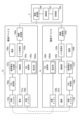
- Fig. 1 is a block diagram showing the configuration of a biosignal measurement system according to this embodiment.
- the biosignal measurement system is composed of a sensor device 1a attached to the right side of a subject, a sensor device 1b attached to the left side, and a biosignal generating device 2.
- the sensor device 1a includes an electrode 101a that contacts the skin on the right side of the subject, an amplifier 102a that amplifies the bioelectric potential detected by the electrode 101a, an AD converter 103a that converts the amplified bioelectric potential into digital data, a wireless transmitter 104a that wirelessly transmits the digital data output from the AD converter 103a to the biosignal generating device 2, an FM (Frequency Modulation) transmitter 105a that frequency-modulates a carrier wave in accordance with the bioelectric potential amplified by the amplifier 102a and transmits the modulated signal to the sensor device 1b, and a sensor device 1c.
- an amplifier 102a that amplifies the bioelectric potential detected by the electrode 101a
- an AD converter 103a that converts the amplified bioelectric potential into digital data
- a wireless transmitter 104a that wirelessly transmits the digital data output from the AD converter 103a to the biosignal generating device 2
- an FM (Frequency Modulation) transmitter 105a that frequency-modulates
- the sensor device 1b includes an FM receiver 106a that demodulates the modulated signal transmitted from the sensor device 1b to extract biopotential information, a reference potential generator 107a that generates a reference potential for the amplifier 102a, a power supply 108a that supplies power to the amplifier 102a, the AD converter 103a, the wireless transmitter 104a, the FM transmitter 105a, the FM receiver 106a, and the reference potential generator 107a, a transmitting antenna 109a that wirelessly transmits the modulated signal output from the FM transmitter 105a to the sensor device 1b, and a receiving antenna 110a that receives the modulated signal transmitted from the sensor device 1b.
- the sensor device 1b includes an electrode 101b that contacts the skin on the left side of the subject, an amplifier 102b that amplifies the bioelectric potential detected by the electrode 101b, an AD converter 103b that converts the amplified bioelectric potential into digital data, a wireless transmitter 104b that wirelessly transmits the digital data output from the AD converter 103b to the biosignal generating device 2, an FM transmitter 105b that frequency-modulates a carrier wave in response to the bioelectric potential amplified by the amplifier 102b and transmits the modulated signal to the sensor device 1a, and a digital signal transmitted from the sensor device 1a.
- an FM receiving unit 106b that demodulates the modulated signal and extracts bioelectric potential information
- a reference potential generating unit 107b that generates a reference potential for the amplifier unit 102b
- a power supply 108b that supplies power to the amplifier unit 102b
- the AD conversion unit 103b the wireless transmission unit 104b
- the FM transmission unit 105b the FM receiving unit 106b
- the reference potential generating unit 107b a transmitting antenna 109b that wirelessly transmits the modulated signal output from the FM transmission unit 105b to the sensor device 1a
- a receiving antenna 110b that receives the modulated signal transmitted from the sensor device 1a.
- the biosignal generating device 2 includes a wireless receiving unit 200 that receives digital data transmitted from the sensor devices 1a and 1b, a calculation unit 201 that calculates an electrocardiogram signal, and a memory unit 202 that stores the electrocardiogram signal calculated by the calculation unit 201.
- sensor devices 1a, 1b are attached to at least two locations on the limbs as measurement sites that are comfortable for the subject. By adopting such a mounting form for sensor devices 1a, 1b, it is possible to significantly reduce the feeling of pressure and discomfort caused by wearing clothing.
- the biosignal measurement system can be used not only for electrocardiograms, but also for measuring myoelectricity, electroencephalograms, etc.
- the sensor devices 1a and 1b are in the shape of, for example, gloves, rings, socks, slippers, or wristbands.
- the person being measured wears the sensor devices 1a and 1b on their right and left hands, respectively, like gloves or rings.
- the person being measured wears the sensor devices 1a and 1b on their right and left feet, respectively, like socks, or slippers, respectively.
- the person being measured wears the sensor devices 1a and 1b on their right and left hands, respectively, like wristbands.
- Electrodes 101a and 101b can be made of various materials and configurations. Any material can be used, including Ag/AgCl electrodes used in medical applications, conductive cloth electrodes, and metal electrodes. By using cloth or metal electrodes that do not need to be directly attached to the subject's body, and by using a non-contact electrode configuration in which the electrodes are worn over clothing, it is possible to further increase the subject's freedom of movement.
- the bioelectric potential detected by the electrodes 101a and 101b is a very weak signal, so signal amplification by the amplifiers 102a and 102b is necessary.
- the amplifiers 102a and 102b require a high input impedance to reduce loss of the bioelectric potential.
- the resistance that determines the input impedance also affects the gain setting and further contributes directly as thermal noise, lowering the signal-to-noise ratio of the bioelectric potential.
- a non-inverting amplifier circuit has the characteristic that noise is less likely to increase even when configured with a high input impedance. Therefore, it is effective to use a non-inverting amplifier circuit as the amplifiers 102a and 102b. It is also possible to provide a low-pass filter in the amplifiers 102a and 102b.
- the reference potential of the two amplifiers 102a and 102b is common.
- the reference potentials of the amplifiers 102a and 102b may not match, which may result in a deterioration in measurement accuracy.
- bioelectric potential information is transmitted and received between sensor devices 1a and 1b, and the reference potential Vref is made common in the amplifiers 102a and 102b of each sensor device 1a and 1b.
- the bioelectric potential detected by the electrode 101b of the sensor device 1b and amplified by the amplifier 102b is wirelessly transmitted to the sensor device 1a by the FM transmitter 105b.
- the FM receiver 106a of the sensor device 1a demodulates the signal transmitted from the sensor device 1b and received by the receiving antenna 110a to extract the bioelectric potential information.
- the reference potential generating unit 107a of the sensor device 1a generates the reference potential Vref by calculating the additive average of the biopotential detected by the electrode 101a and amplified by the amplifier 102a and the biopotential output from the FM receiving unit 106a (the biopotential transmitted from the sensor device 1b).
- FIG. 2 is a circuit diagram showing an example of the configuration of the amplifier 102a.
- the amplifier 102a is composed of an operational amplifier A1 and resistors R1 and R2.
- a reference potential Vref is supplied from a reference potential generating unit 107a to one end of resistor R1 of the amplifier 102a.
- the bioelectric potential detected by the electrode 101a of the sensor device 1a and amplified by the amplifier 102a is wirelessly transmitted to the sensor device 1b by the FM transmitter 105a.
- the FM receiver 106b of the sensor device 1b demodulates the signal transmitted from the sensor device 1a and received by the receiving antenna 110b to extract the bioelectric potential information.
- the reference potential generating unit 107b of the sensor device 1b generates a reference potential Vref by calculating the average of the biopotential detected by the electrode 101b and amplified by the amplifier 102b and the biopotential output from the FM receiver 106b (the biopotential transmitted from the sensor device 1a), and supplies the reference potential Vref to the amplifier 102b.
- the amplifier 102b has the same configuration as the amplifier 102a.
- Each of the reference potential generating units 107a and 107b is preferably configured, for example, from a single-stage operational amplifier.
- the AD conversion unit 103a of the sensor device 1a converts the bioelectric potential amplified by the amplifier unit 102a into digital data.
- the wireless transmission unit 104a wirelessly transmits the bioelectric potential data output from the AD conversion unit 103a to the biosignal generating device 2.
- the AD conversion unit 103b of the sensor device 1b converts the bioelectric potential amplified by the amplifier unit 102b into digital data.
- the wireless transmission unit 104b wirelessly transmits the bioelectric potential data output from the AD conversion unit 103b to the biosignal generating device 2.
- any wireless communication standard can be applied between the wireless transmitting units 104a, 104b and the wireless receiving unit 200 of the biosignal generating device 2, such as carrier communication, Wi-Fi (registered trademark), Bluetooth (registered trademark), etc.
- a short-range communication standard such as Bluetooth
- a smartphone or other terminal close to the subject can be used as the biosignal generating device 2.
- Wi-Fi or the like a server device or the like can be used as the biosignal generating device 2.
- the calculation unit 201 of the biosignal generating device 2 calculates the difference between the biopotential transmitted from the sensor device 1a and the biopotential transmitted from the sensor device 1b as an electrocardiogram signal.
- the electrocardiogram signal is stored in the storage unit 202.
- the FM transmitter 105a of the sensor device 1a FM modulates the carrier wave according to the bioelectric potential amplified by the amplifier 102a, and transmits the modulated signal from the transmitting antenna 109a to the sensor device 1b.
- the FM receiver 106a of the sensor device 1a demodulates the modulated signal transmitted from the sensor device 1b and received by the receiving antenna 110a to extract information about the bioelectric potential.
- the FM transmitter 105b of the sensor device 1b FM-modulates the carrier wave in response to the bioelectric potential amplified by the amplifier 102b, and transmits the modulated signal from the transmitting antenna 109b to the sensor device 1a.
- the FM receiver 106b of the sensor device 1b demodulates the modulated signal transmitted from the sensor device 1a and received by the receiving antenna 110b, and extracts the bioelectric potential information.
- a voltage controlled oscillator (VCO) is used for FM modulation of the carrier wave in the FM transmission units 105a and 105b, and a phase locked loop (PLL) is used for demodulation in the FM reception units 106a and 106b.
- VCO voltage controlled oscillator
- PLL phase locked loop
- the VCO generally changes the oscillation frequency using a varactor diode, whose capacitance changes with voltage.
- the oscillation frequency f of the VCO is expressed by the following equation and is determined by the resonant frequency due to the inductance L and capacitance C.
- Capacitance C is often composed of a varactor diode and multiple capacitors.
- a VCO is also used as a component of the PLL in FM receivers 106a and 106b. For this reason, it is necessary to set the same oscillation frequency between the VCOs of FM transmitters 105a and 105b and FM receivers 106a and 106b.
- FIG. 3 shows an example of individual differences in VCO oscillation frequency. It shows the control voltage-oscillation frequency characteristics of five VCOs 300-1 to 300-5. Each VCO is designed using the same elements, and in theory should show the same control voltage-oscillation frequency characteristics, but large individual differences occur.
- an offset error of approximately 200 kHz occurs between VCOs 300-2 and 300-5, which translates into an error of approximately 1 V when converted into voltage.
- the circuit voltage used in wearable devices and the like is 3 V to 5 V, this error is equivalent to more than 20% of the circuit voltage, and has an extremely large effect on the measurement results.
- the bioelectric potentials detected by the sensor devices 1a and 1b are transmitted and received between them to match the reference potentials Vref of the amplifiers 102a and 102b, improving the measurement accuracy of the electrocardiogram signal.
- the bioelectric potentials detected by the sensor devices 1a and 1b cannot be correctly demodulated, the measurement accuracy of the electrocardiogram signal deteriorates significantly, so it is very important to correct the error in the VCO oscillation frequency.
- One example of a correction method is to add an offset to the reference potential Vref generated by the reference potential generating units 107a and 107b, or to adjust the amplification of the reference potential generating units 107a and 107b to adjust the slope of the VCO's control voltage-oscillation frequency.
- this correction method uses a linear correction function, which complicates the processing because it must solve two variables: the slope and intercept of the VCO's control voltage-oscillation frequency.
- an inverting amplifier circuit is required, but inverting the output makes the noise gain larger than the signal gain, increasing noise.
- variable resistors when used to adjust the amplification of the reference potential generating units 107a and 107b, there is a possibility that the correction may shift over time due to drift caused by time or temperature changes. Also, when the difference in the oscillation frequency of the VCO is large, the control voltage corresponding to the oscillation frequency may saturate at the value of the power supply voltage (GND or VDD), and information for calculating the first-order correction function may not be obtained, making it impossible to perform correction.
- VDD power supply voltage
- correction is performed by changing the offset of the oscillation frequency.
- correction units 1064a and 1064b are provided in the VCOs of the FM receivers 106a and 106b of the sensor devices 1a and 1b.
- FIG. 4 shows the basic configuration of the FM receiver 106a.
- the FM receiver 106a has a PLL configuration and is composed of a VCO 1060a, a phase comparator 1061a that performs phase comparison between the modulated signal Vs received by the receiving antenna 110a and the output signal Vo of the VCO 1060a, a low-pass filter (LPF) 1062a that outputs the result of low-pass filtering the output signal Ve of the phase comparator 1061a as a demodulated biopotential, and a correction unit 1064a.
- the output of the LPF 1062a is input to the VCO 1060a as a control voltage Vctl.
- the configuration of the FM receiver 106b is the same as that of the FM receiver 106a.
- the configuration in FIG. 4 is just one example, and the FM receiving units 106a and 106b are not limited to the configuration in FIG. 4.
- an amplifier unit may be inserted between the LPF 1062a and the VCO 1060a, and the voltage obtained by amplifying the bioelectric potential output from the LPF 1062a may be used as the control voltage Vctl for the VCO 1060a.
- the VCO 1060a is composed of a varactor diode D1, capacitors C1 and C2, an inductor L1, and an amplifier section 1065. If the capacitance fluctuation component due to the varactor diode D1 and the capacitor C1 is C var , the constant component of the capacitance due to the capacitor C2 is C const , and the inductance of the inductor L1 is L, then the oscillation frequency f of the VCO 1060a is given by the following equation.
- FIG. 6 shows a configuration in which a correction unit 1064a is added to a VCO 1060a.
- the oscillation frequency f of the VCO 1060a decreases when the capacitance is increased, and increases when the capacitance is decreased. Therefore, by providing variable capacitances C3 and C4 in series and parallel with the capacitor C1 as the correction unit 1064a, the offset of the oscillation frequency f of the VCO 1060a can be changed.
- variable capacitances C3 and C4 can be configured with varactor diodes, MEMS (Micro Electro Mechanical Systems) variable capacitors, or an array of capacitors.
- varactor diodes MEMS (Micro Electro Mechanical Systems) variable capacitors
- MEMS variable capacitors or an array of capacitors.
- implementation using varactor diodes or MEMS variable capacitors is advantageous because it requires fewer components and is easier to control.
- LSI Large Scale Integration
- the configuration of the correction unit 1064b is the same as that of the correction unit 1064a.
- the configurations of the FM receiving units 106a, 106b and the correction units 1064a, 1064b are not limited to those shown in Figures 4 to 6, and may be circuit configurations that perform similar functions.
- FIG. 7 is a flow chart explaining a method for adjusting the FM receivers 106a and 106b (correction units 1064a and 1064b).
- an operator who wishes to adjust the FM receivers 106a and 106b applies a predetermined arbitrary voltage x [V] to the FM transmitter 105a of the sensor device 1a, FM-modulates the carrier wave according to the voltage x [V], and transmits the modulated signal from the transmitting antenna 109a to the sensor device 1b (step S100 in FIG. 7).
- the FM receiver 106b of the sensor device 1b demodulates the modulated signal transmitted from the sensor device 1a and received by the receiving antenna 110b, and outputs a voltage y [V] (step S101 in FIG. 7). Due to an error in the VCO of the FM receiver 106b, the voltage y [V] differs from the original x [V]. Therefore, the operator adjusts the value of the variable capacitance of the correction unit 1064b so that the VCO output voltage y [V] matches x [V] (step S102 in FIG. 7). The value of the variable capacitance can be set by the control voltage Vctl2.
- the worker applies a voltage x [V] to the FM transmitter 105b of the sensor device 1b, FM-modulates the carrier wave according to the voltage x [V], and transmits the modulated signal from the transmitting antenna 109b to the sensor device 1a (step S103 in FIG. 7).
- the FM receiver 106a of the sensor device 1a demodulates the modulated signal transmitted from the sensor device 1b and received by the receiving antenna 110a, and outputs a voltage y [V] (step S104 in FIG. 7).
- the operator adjusts the values of the variable capacitances C3 and C4 of the correction unit 1064a so that the output voltage y [V] of the VCO of the FM receiver 106a matches x [V] (step S105 in FIG. 7).
- the adjustment of the FM receivers 106a and 106b (correction units 1064a and 1064b) is complete, and the oscillation frequency of the VCO can be corrected, so measurement of the biosignal can begin.
- the FM receiver 106b of sensor device 1b is adjusted first, and then the FM receiver 106a of sensor device 1a is adjusted, but the order may be reversed, or the adjustments may be performed simultaneously.
- the present invention makes it possible to use more sensor devices, rather than just pairing sensor devices.
- the configuration in which correction units 1064a, 1064b are provided in FM receiving units 106a, 106b is particularly suitable for human body communication, which uses the body of the person being measured as a transmission path.
- human body communication in which radio waves are transmitted into the air, there is a possibility that erroneous correction will be made in accordance with unnecessary modulated signals flying around in space.
- the allowable radio wave intensity differs depending on the frequency band. For this reason, there is a risk that an error in the oscillation frequency will enter a frequency band with strict intensity restrictions and cause correction.
- human body communication is less susceptible to the external environment.
- there is less electric field radiation into the external environment there is no need to adjust the transmission frequency to a specific frequency as in radio communication. Instead, it is sufficient to adjust the oscillation frequency of the VCOs of the FM receivers 106a and 106b to the transmission frequency of the sensor devices 1a and 1b, so the correction function can be achieved with a simple mechanism.
- FIG. 8 The configuration of a biosignal measurement system when using human body communication is shown in Figure 8.
- electrodes 109a', 110a' that come into contact with the skin on the right side of the subject are provided instead of the antennas 109a, 110a in Figure 1.
- electrodes 109b', 110b' that come into contact with the skin on the left side of the subject are provided instead of the antennas 109b, 110b.
- the FM transmitter 105a of the sensor device 1a FM-modulates a carrier wave in response to the bioelectric potential amplified by the amplifier 102a, and transmits the modulated signal from the electrode 109a' to the sensor device 1b via the body of the person being measured.
- the FM receiver 106a demodulates the modulated signal transmitted from the sensor device 1b and received by the electrode 110a' to extract information about the bioelectric potential.
- the FM transmitter 105b of the sensor device 1b FM-modulates the carrier wave in response to the biopotential amplified by the amplifier 102b, and transmits the modulated signal from the electrode 109b' to the sensor device 1a via the body of the person being measured.
- the FM receiver 106b demodulates the modulated signal transmitted from the sensor device 1a and received by the electrode 110b' to extract information about the biopotential.
- Power for communication accounts for a large portion of the power consumption of the sensor devices 1a and 1b.
- the signal strength attenuates inversely proportional to the square of the propagation distance.
- the signal attenuation is limited to an amount inversely proportional to the propagation distance. For this reason, the use of human body communication makes it possible to transmit data with less transmission power. Sending and receiving data via the human body can contribute to reducing power consumption.
- the oscillation frequency of the VCO of the FM receivers 106a, 106b can be corrected, so that the variation in the oscillation frequency of the FM transmitters 105a, 105b and the FM receivers 106a, 106b caused by the influence of the external environment can be kept to a minimum, and the reference potential for the potential measurement of the sensor devices 1a, 1b can be made common, so that the measurement accuracy of the biopotential can be improved.
- correction units 1064a and 1064b are provided in the VCOs of the FM receiving units 106a and 106b of the sensor devices 1a and 1b, but a correction unit may be provided in the VCOs of the FM transmitting units 105a and 105b.
- Figure 9 shows a configuration in which correction units 1054a and 1054b are provided in the VCOs of the FM transmitting units 105a and 105b in the configuration of Figure 1
- Figure 10 shows a configuration in which correction units 1054a and 1054b are provided in the VCOs of the FM transmitting units 105a and 105b in the configuration of Figure 8.
- FIG. 11 is a diagram showing the basic configuration of the FM transmitter 105a in the configuration of FIG. 9 and FIG. 10.
- the FM transmitter 105a is composed of a VCO 1050a, a crystal oscillator 1051a that outputs a carrier wave Vc, a phase comparator 1052a that performs phase comparison between the carrier wave Vc and the output signal Vo of the VCO 1050a, an LPF 1053a that outputs the result of low-pass filtering the output signal Ve of the phase comparator 1052a, and a correction unit 1054a.
- a signal obtained by mixing the output signal of the LPF 1053a and the bioelectric potential Vs2 amplified by the amplifier 102a is input to the VCO 1050a as a control voltage Vctl.
- the output signal Vo of the VCO 1050a is output to the transmitting antenna 109a or the electrode 109a' as a modulated signal.
- the configuration of the FM transmitter 105b is the same as that of the FM transmitter 105a.
- the configuration in FIG. 11 is just one example, and the FM transmitters 105a and 105b are not limited to the configuration in FIG. 11.
- an amplifier may be inserted between the VCO 1050a and the transmitting antenna 109a or the electrode 109a' to amplify the modulated signal.
- a frequency divider may be inserted between the crystal oscillator 1051a and the phase comparator 1052a, and between the VCO 1050a and the phase comparator 1052a.
- FIG. 12 shows a configuration in which a correction unit 1054a is added to a VCO 1050a.
- the configuration of the VCO 1050a is the same as that of the VCO 1060a, and the configuration of the correction unit 1054a is the same as that of the correction unit 1064a, so their explanations are omitted.
- the configuration of the correction unit 1054b is the same as that of the correction unit 1054a.
- FIG. 13 is a flow chart explaining a method for adjusting the FM transmitters 105a and 105b (correction units 1054a and 1054b) of this embodiment.
- an operator who wishes to adjust the FM transmitters 105a and 105b applies a predetermined arbitrary voltage x [V] to the FM transmitter 105a of the sensor device 1a, FM modulates the carrier wave according to the voltage x [V], and transmits the modulated signal from the transmitting antenna 109a or electrode 109a' to the sensor device 1b (step S200 in FIG. 13).
- the FM receiver 106b of the sensor device 1b demodulates the modulated signal transmitted from the sensor device 1a and received by the receiving antenna 110b or the electrode 110b', and outputs a voltage y [V] (step S201 in FIG. 13).
- the operator adjusts the values of the variable capacitances C3 and C4 of the correction unit 1054a of the FM transmitter 105a so that the output voltage y [V] of the FM receiver 106b matches x [V] (step S202 in FIG. 13).
- the value of the variable capacitance can be set by the control voltage Vctl2.
- the worker applies a voltage x [V] to the FM transmitter 105b of the sensor device 1b, FM-modulates the carrier wave according to the voltage x [V], and transmits the modulated signal from the transmitting antenna 109b or the electrode 109b' to the sensor device 1a (step S203 in FIG. 13).
- the FM receiver 106a of the sensor device 1a demodulates the modulated signal transmitted from the sensor device 1b and received by the receiving antenna 110a or the electrode 110a' and outputs a voltage y [V] (step S204 in FIG. 13).
- the operator adjusts the value of the variable capacitance of the correction unit 1054b of the FM transmitter 105b so that the output voltage y [V] of the FM receiver 106a matches x [V] (step S205 in FIG. 13).
- the adjustment of the FM transmitters 105a and 105b (correction units 1054a and 1054b) is complete, and the oscillation frequency of the VCO can be corrected, so measurement of the biosignal can begin.
- the FM transmitter 105a of sensor device 1a is adjusted first, and then the FM transmitter 105b of sensor device 1b is adjusted, but the order may be reversed, or they may be adjusted simultaneously.
- the correction section is provided in either the FM transmitting section or the FM receiving section, but the correction section may be provided in both the FM transmitting section and the FM receiving section.
- FIG. 14 is a block diagram showing the configuration of the biosignal measurement system according to this embodiment.
- the configuration of the FM receivers 106a and 106b is as described in the first embodiment, and the configuration of the FM transmitters 105a and 105b is as described in the second embodiment.
- the configuration of the biosignal measurement system when human body communication is used is shown in FIG. 15.
- the amount of correction is increased when the correction is not completed using the methods of the first and second embodiments.
- FIG. 16 is a flowchart explaining a method for adjusting the FM transmitters 105a and 105b and the FM receivers 106a and 106b (correction units 1054a, 1054b, 1064a, and 1064b) in this embodiment. This flowchart shows the case where the correction of the sensor device 1b is insufficient.
- the operator applies a predetermined arbitrary voltage x1 [V] to the FM transmitter 105a of the sensor device 1a, FM-modulates the carrier wave according to the voltage x1 [V], and transmits the modulated signal from the transmitting antenna 109a or electrode 109a' to the sensor device 1b (step S300 in FIG. 16).
- the FM receiver 106b of the sensor device 1b demodulates the modulated signal transmitted from the sensor device 1a and received by the receiving antenna 110b or the electrode 110b' and outputs a voltage y1 [V] (step S301 in FIG. 16).
- the operator adjusts the value of the variable capacitance of the correction unit 1064b so that the output voltage y1 [V] of the FM receiver 106b matches x1 [V] (step S302 in FIG. 16).
- the operator applies a predetermined arbitrary voltage x2 [V] to the FM transmitter 105b of the sensor device 1b, FM-modulates the carrier wave according to the voltage x2 [V], and transmits the modulated signal from the transmitting antenna 109b or the electrode 109b' to the sensor device 1a (step S303 in FIG. 16).
- the FM receiver 106a of the sensor device 1a demodulates the modulated signal transmitted from the sensor device 1b and received by the receiving antenna 110a or the electrode 110a' and outputs a voltage y2 [V] (step S304 in FIG. 16).
- the operator adjusts the values of the variable capacitances C3 and C4 of the correction unit 1064a so that the output voltage y2 [V] of the FM receiver 106a matches x2 [V] (step S305 in FIG. 16).
- the adjustments in steps S300 to S302 and steps S303 to S305 may be performed simultaneously.
- the output voltages y1 [V] and x1 [V] of the FM receiving unit 106b do not match, and correction is not complete.
- the operator applies a predetermined arbitrary voltage ⁇ 2 [V] to the FM transmitting unit 105b of the sensor device 1b for which correction has not been completed, FM modulates the carrier wave according to the voltage ⁇ 2 [V], and transmits the modulated signal from the transmitting antenna 109b or the electrode 109b' to the sensor device 1a (step S306 in FIG. 16).
- the FM receiver 106a of the sensor device 1a demodulates the modulated signal transmitted from the sensor device 1b and received by the receiving antenna 110a or the electrode 110a', and outputs a voltage ⁇ 2 [V] (step S307 in FIG. 16).
- the operator adjusts the oscillation frequency of the VCO 1050a of the FM transmitter 105a to increase, i.e., adjusts the values of the variable capacitances C3 and C4 of the correction unit 1054a to decrease. If the output voltage ⁇ 2 [V] of the FM receiver 106a is less than the threshold voltage Vth [V], the operator adjusts the oscillation frequency of the VCO 1050a to decrease, i.e., adjusts the values of the variable capacitances C3 and C4 of the correction unit 1054a to increase (step S308 in FIG. 16).
- the threshold voltage Vth may be, for example, Vdd/2 (Vdd is the power supply voltage).
- the amount of correction by the correction unit 1054a at this time may be the maximum amount that can be selected. If the correction amounts for transmission and reception are all equal, the amount of correction by the correction unit 1054a may be changed to the maximum amount, so that repeated adjustment work is not necessary many times, and the adjustment work can be performed easily.
- the processing in steps S309 to S311 in FIG. 16 is the same as steps S300 to S302.
- the adjustment of the FM transmitters 105a and 105b and the FM receivers 106a and 106b (correction units 1054a, 1054b, 1064a, 1064b) is complete, and the oscillation frequency of the VCO can be corrected, so measurement of the biosignal can begin.
- the oscillation frequency f1 of the VCO of the FM transmitter 105a is adjusted to the upper limit value f1H by the correction unit 1054a, the upper limit value f1H falls within the correction range of the sensor device 1b, making perfect correction possible. Correction can be made by the same argument even if the magnitude relationship of the frequencies differs.
- the amount of correction in the FM transmission unit and the FM reception unit can be reduced. If the capacitance C const described in the formula (2) is corrected too much, the ratio between the capacitances C const and C var may be lost, and the slope of the VCO control voltage-oscillation frequency characteristic may shift between the FM transmission unit and the FM reception unit. According to this embodiment, such a shift in slope can be suppressed.
- the operator applies a predetermined arbitrary voltage ⁇ 1 [V] to the FM transmitter 105a of the sensor device 1a for which correction has not been completed, FM-modulates the carrier wave according to the voltage ⁇ 1 [V], and transmits the modulated signal from the transmitting antenna 109a or electrode 109a' to the sensor device 1b (FIG. 18, step S312).
- the FM receiver 106b of the sensor device 1b demodulates the modulated signal transmitted from the sensor device 1a and received by the receiving antenna 110b or the electrode 110b', and outputs a voltage ⁇ 1 [V] (step S313 in FIG. 18).
- the operator adjusts the oscillation frequency of the VCO of the FM transmitter 105b to increase, i.e., to decrease the value of the variable capacitance of the correction unit 1054b. If the output voltage ⁇ 1 [V] of the FM receiver 106b is less than the threshold voltage Vth [V], the operator adjusts the oscillation frequency of the VCO of the FM transmitter 105b to decrease, i.e., to increase the value of the variable capacitance of the correction unit 1054b (step S314 in FIG. 18). The processing in steps S315 to S317 in FIG. 18 is the same as steps S303 to S305.
- the biosignal generating device 2 is provided separately from the sensor devices 1a and 1b, but the configuration of the biosignal generating device 2 may be implemented in either one of the sensor devices 1a or 1b.
- Fig. 19 is a block diagram showing the configuration of the biosignal measuring system of this embodiment.
- the wireless transmitting unit 104b of the sensor device 1b is not necessary.
- the wireless receiving unit 200 provided in the sensor device 1b receives the biopotential data transmitted from the sensor device 1a.
- the calculation unit 201 calculates the difference between the biopotential transmitted from the sensor device 1a and the biopotential output from the AD conversion unit 103b as an electrocardiogram signal.
- the electrocardiogram signal is stored in the memory unit 202.
- the configuration of the biosignal generating device 2 is provided in the sensor device 1b, but it goes without saying that it may be provided in the sensor device 1a.
- the configuration in FIG. 19 shows an example in which this embodiment is applied to the configuration in FIG. 1, this embodiment may also be applied to the configurations in FIGS. 8 to 10, 14, and 15.
- the adjustment is performed by wireless communication even during the adjustment before starting the measurement of the biosignal, but a wired connection section may be provided in the sensor devices 1a and 1b, and the adjustment may be performed by wired communication.
- Fig. 20 is a block diagram showing the configuration of the biosignal measurement system of this embodiment.
- Sensor device 1a includes an electrode 101a, an amplifier 102a, an AD converter 103a, a wireless transmitter 104a, an FM transmitter 105a, an FM receiver 106a, a reference potential generator 107a, a power source 108a, a transmitter antenna 109a, a receiver antenna 110a, and wired connection parts 111a and 112a for wired communication with sensor device 1b.
- Sensor device 1b includes electrode 101b, amplifier 102b, AD converter 103b, wireless transmitter 104b, FM transmitter 105b, FM receiver 106b, reference potential generator 107b, power supply 108b, transmitter antenna 109b, receiver antenna 110b, and wired connection units 111b and 112b for wired communication with sensor device 1a.
- adjustments can be made by connecting sensor devices 1a and 1b by wire inside a case that stores the pair of sensor devices 1a and 1b.
- the power sources 108a and 108b of sensor devices 1a and 1b are batteries, and a device for charging the batteries is required.
- wired connection sections 111a and 112b are connected by wiring inside the charging case, and wired connection sections 111b and 112a are connected at the same time as the batteries are charged.
- the adjustment method differs from the first to fourth embodiments in that wired communication is used instead of wireless communication in steps S100 and S103 in FIG. 7, steps S200 and S203 in FIG. 13, steps S300, S303, S306, and S309 in FIG. 16, and steps S300, S303, S312, and S315 in FIG. 18.
- FIG. 20 shows an example in which this embodiment is applied to the configuration in FIG. 1, but this embodiment may also be applied to the configurations in FIG. 8 to FIG. 10, FIG. 14, FIG. 15, and FIG. 19.
- sensor devices 1a and 1b may be connected by wiring without going through a charging case.
- the calculation unit 201 and memory unit 202 described in the first to fifth embodiments can be realized by a computer equipped with a CPU (Central Processing Unit), a memory device, and an interface, and a program that controls these hardware resources.
- a computer equipped with a CPU (Central Processing Unit), a memory device, and an interface, and a program that controls these hardware resources.
- An example of the configuration of this computer is shown in Figure 21.
- the computer comprises a CPU 400, a storage device 401, and an interface device (I/F) 402.
- the I/F 402 is connected to the hardware of the wireless receiving unit 200, etc.
- a program for implementing the method of the present invention is stored in the storage device 401.
- the CPU 400 executes the processes described in the first to fifth embodiments in accordance with the program stored in the storage device 401.
- at least a part of the calculation unit 201 may be configured with hardware logic such as an FPGA (field-programmable gate array).
- the biosignal measurement system of the present invention comprises a first sensor device configured to be attached to one of the right and left sides of a subject, and a second sensor device configured to be attached to the other of the right and left sides.
- Each of the first and second sensor devices comprises a first electrode configured to come into contact with the skin of the subject, an amplifier configured to amplify a biopotential detected by the first electrode, a transmitter configured to modulate a carrier wave according to the biopotential amplified by the amplifier and wirelessly transmit a modulated signal to the other sensor device, a receiver configured to demodulate the modulated signal transmitted from the other sensor device to extract information on the biopotential, a reference potential generator configured to generate a reference potential for the amplifier based on the biopotential amplified by the amplifier and the biopotential output from the receiver, and a correction unit configured to correct at least one of the oscillation frequency of a voltage-controlled oscillator used for modulation of the transmitter and the oscillation frequency of a voltage-controlled oscillator used for de
- each of the first sensor device and the second sensor device further includes a transmitting antenna for wirelessly transmitting the modulated signal output from the transmitter to the other sensor device, and a receiving antenna for receiving the modulated signal transmitted from the other sensor device.
- each of the first sensor device and the second sensor device further includes a second electrode for transmitting the modulated signal output from the transmitter to the other sensor device via the body of the subject, and a third electrode for receiving the modulated signal from the other sensor device via the body of the subject.
- the correction unit has a variable capacitance that can change at least one of the oscillation frequency of the voltage-controlled oscillator used for modulation of the transmission unit and the oscillation frequency of the voltage-controlled oscillator used for demodulation of the reception unit.
- each of the first sensor device and the second sensor device further includes a first wired connection unit for connecting the transmitting unit of the first sensor device to the receiving unit of the other sensor device by wire, and a second wired connection unit for connecting the receiving unit of the first sensor device to the transmitting unit of the other sensor device by wire.
- the correction unit of each of the first sensor device and the second sensor device is configured to correct the oscillation frequency of a voltage-controlled oscillator used for demodulation of the receiving unit of its own sensor device, and the oscillation frequency of the voltage-controlled oscillator used for demodulation of the receiving unit of its own sensor device is adjusted by the correction unit of its own sensor device so that a first potential given to the transmitting unit of the other sensor device to modulate the carrier wave matches a second potential output from the receiving unit of its own sensor device in response to a modulated signal transmitted from the other sensor device.
- the correction unit of each of the first sensor device and the second sensor device is configured to correct the oscillation frequency of a voltage-controlled oscillator used to modulate the transmission unit of its own sensor device, and the oscillation frequency of the voltage-controlled oscillator used to modulate the transmission unit of its own sensor device is adjusted by the correction unit of its own sensor device so that a first potential given to the transmission unit of its own sensor device to modulate the carrier wave matches a second potential output from the receiving unit of the other sensor device in response to a modulated signal transmitted from its own sensor device.
- the correction units of the first sensor device and the second sensor device each include a first correction unit configured to correct the oscillation frequency of a voltage-controlled oscillator used for demodulation of the receiving unit of the sensor device itself, and a second correction unit configured to correct the oscillation frequency of a voltage-controlled oscillator used for modulation of the transmitting unit of the sensor device itself, and a first potential given to the transmitting unit of the other sensor device to modulate the carrier wave and a second potential output from the receiving unit of the sensor device itself in response to a modulated signal transmitted from the other sensor device are matched.
- the oscillation frequency of the voltage-controlled oscillator used to demodulate the receiving section of the sensor device of the sensor device itself is adjusted by the first correction section of the sensor device of the sensor device itself, and further, when the first potential and the second potential do not match, when a third potential is applied to the transmitting section of the sensor device of the sensor device to modulate the carrier wave, the oscillation frequency of the voltage-controlled oscillator used to modulate the transmitting section of the other sensor device is adjusted by the second correction section of the other sensor device according to the comparison result between a fourth potential output from the receiving section of the other sensor device in response to the modulated signal transmitted from the sensor device of the sensor device itself and a predetermined threshold voltage.
- the present invention can be applied to technology for measuring biological signals.
Landscapes
- Engineering & Computer Science (AREA)
- Life Sciences & Earth Sciences (AREA)
- Computer Networks & Wireless Communication (AREA)
- Signal Processing (AREA)
- Health & Medical Sciences (AREA)
- Biomedical Technology (AREA)
- Surgery (AREA)
- Pathology (AREA)
- Physics & Mathematics (AREA)
- Heart & Thoracic Surgery (AREA)
- Medical Informatics (AREA)
- Molecular Biology (AREA)
- Biophysics (AREA)
- Animal Behavior & Ethology (AREA)
- General Health & Medical Sciences (AREA)
- Public Health (AREA)
- Veterinary Medicine (AREA)
- Measurement And Recording Of Electrical Phenomena And Electrical Characteristics Of The Living Body (AREA)
- Arrangements For Transmission Of Measured Signals (AREA)
Priority Applications (2)
| Application Number | Priority Date | Filing Date | Title |
|---|---|---|---|
| PCT/JP2022/039662 WO2024089758A1 (ja) | 2022-10-25 | 2022-10-25 | 生体信号計測システム |
| JP2024552546A JP7852735B2 (ja) | 2022-10-25 | 2022-10-25 | 生体信号計測システム |
Applications Claiming Priority (1)
| Application Number | Priority Date | Filing Date | Title |
|---|---|---|---|
| PCT/JP2022/039662 WO2024089758A1 (ja) | 2022-10-25 | 2022-10-25 | 生体信号計測システム |
Publications (1)
| Publication Number | Publication Date |
|---|---|
| WO2024089758A1 true WO2024089758A1 (ja) | 2024-05-02 |
Family
ID=90830233
Family Applications (1)
| Application Number | Title | Priority Date | Filing Date |
|---|---|---|---|
| PCT/JP2022/039662 Ceased WO2024089758A1 (ja) | 2022-10-25 | 2022-10-25 | 生体信号計測システム |
Country Status (2)
| Country | Link |
|---|---|
| JP (1) | JP7852735B2 (https=) |
| WO (1) | WO2024089758A1 (https=) |
Cited By (1)
| Publication number | Priority date | Publication date | Assignee | Title |
|---|---|---|---|---|
| WO2026004033A1 (ja) * | 2024-06-27 | 2026-01-02 | Ntt株式会社 | 計測システムおよび信号読み出し装置 |
Citations (2)
| Publication number | Priority date | Publication date | Assignee | Title |
|---|---|---|---|---|
| JP2007301229A (ja) * | 2006-05-12 | 2007-11-22 | Casio Comput Co Ltd | 生体情報測定装置及び生体情報測定システム |
| JP2008211765A (ja) * | 2007-02-27 | 2008-09-11 | Tanita Corp | 活動情報計 |
Family Cites Families (5)
| Publication number | Priority date | Publication date | Assignee | Title |
|---|---|---|---|---|
| JP3433645B2 (ja) * | 1997-04-02 | 2003-08-04 | スズキ株式会社 | 筋電位計 |
| US20020045836A1 (en) | 2000-10-16 | 2002-04-18 | Dima Alkawwas | Operation of wireless biopotential monitoring system |
| KR101651537B1 (ko) | 2015-08-24 | 2016-08-26 | 한국과학기술연구원 | 무선 통신을 이용한 심전도 측정 장치 및 방법 |
| EP3721789B1 (en) | 2019-04-12 | 2023-07-26 | BIOTRONIK SE & Co. KG | Intra-cardiac communications to provide direct timing information without electrical interferences |
| CN110327038B (zh) | 2019-05-08 | 2021-11-16 | 京东方科技集团股份有限公司 | 心电采集电路、设备、方法和系统 |
-
2022
- 2022-10-25 WO PCT/JP2022/039662 patent/WO2024089758A1/ja not_active Ceased
- 2022-10-25 JP JP2024552546A patent/JP7852735B2/ja active Active
Patent Citations (2)
| Publication number | Priority date | Publication date | Assignee | Title |
|---|---|---|---|---|
| JP2007301229A (ja) * | 2006-05-12 | 2007-11-22 | Casio Comput Co Ltd | 生体情報測定装置及び生体情報測定システム |
| JP2008211765A (ja) * | 2007-02-27 | 2008-09-11 | Tanita Corp | 活動情報計 |
Cited By (1)
| Publication number | Priority date | Publication date | Assignee | Title |
|---|---|---|---|---|
| WO2026004033A1 (ja) * | 2024-06-27 | 2026-01-02 | Ntt株式会社 | 計測システムおよび信号読み出し装置 |
Also Published As
| Publication number | Publication date |
|---|---|
| JPWO2024089758A1 (https=) | 2024-05-02 |
| JP7852735B2 (ja) | 2026-04-28 |
Similar Documents
| Publication | Publication Date | Title |
|---|---|---|
| Droitcour et al. | Signal-to-noise ratio in Doppler radar system for heart and respiratory rate measurements | |
| JPH11188015A (ja) | 生体信号計測装置 | |
| Zhao et al. | The role and challenges of body channel communication in wearable flexible electronics | |
| EP2336713B1 (en) | System for measuring the shape of an object using a magnetic induction radio sensor | |
| KR101651537B1 (ko) | 무선 통신을 이용한 심전도 측정 장치 및 방법 | |
| Jeon et al. | A 2.5-nW radio platform with an internal wake-up receiver for smart contact lens using a single loop antenna | |
| WO2024089758A1 (ja) | 生体信号計測システム | |
| US10972151B2 (en) | Tag reader transmitter with high-Q antenna | |
| Yoo | Body Area Network: Connecting and powering things together around the human body | |
| US20200167533A1 (en) | Tag reader receiver with high-q antenna | |
| US10028661B2 (en) | Buffered body return receiver | |
| TWI705795B (zh) | 非接觸式相位鎖定暨自我注入鎖定生理信號感測器 | |
| US3195535A (en) | Miniature radiating electrocardiograph | |
| JP7841599B2 (ja) | 生体信号計測システム | |
| US20260026730A1 (en) | Biosignal measurement system | |
| US20260033765A1 (en) | Biosignal measurement system | |
| Kong et al. | Triple-band transmitter with a shared dual-band antenna and adaptive matching for an intraoral tongue drive system | |
| JP7768369B2 (ja) | 生体信号計測システム | |
| EP4179968B1 (en) | Bio-impedance measurement using voltage to current conversion | |
| US5414392A (en) | Amplifier circuit | |
| WO2024116262A1 (ja) | 生体信号計測システム | |
| WO2026053282A1 (ja) | 生体信号計測システム | |
| JPWO2024089758A5 (https=) | ||
| Srivastava et al. | Bio-telemetry and bio-instrumentation technologies for healthcare monitoring systems | |
| CN100508876C (zh) | 人体生理状态检测腕表 |
Legal Events
| Date | Code | Title | Description |
|---|---|---|---|
| 121 | Ep: the epo has been informed by wipo that ep was designated in this application |
Ref document number: 22963410 Country of ref document: EP Kind code of ref document: A1 |
|
| WWE | Wipo information: entry into national phase |
Ref document number: 2024552546 Country of ref document: JP |
|
| NENP | Non-entry into the national phase |
Ref country code: DE |
|
| 122 | Ep: pct application non-entry in european phase |
Ref document number: 22963410 Country of ref document: EP Kind code of ref document: A1 |