WO2024080190A1 - Adsorbant de dioxyde de carbone, utilisation d'adsorbant de dioxyde de carbone, procédé d'isolation de dioxyde de carbone, installation de récupération/réservation de dioxyde de carbone, et procédé de récupération/réservation de dioxyde de carbone - Google Patents
Adsorbant de dioxyde de carbone, utilisation d'adsorbant de dioxyde de carbone, procédé d'isolation de dioxyde de carbone, installation de récupération/réservation de dioxyde de carbone, et procédé de récupération/réservation de dioxyde de carbone Download PDFInfo
- Publication number
- WO2024080190A1 WO2024080190A1 PCT/JP2023/036060 JP2023036060W WO2024080190A1 WO 2024080190 A1 WO2024080190 A1 WO 2024080190A1 JP 2023036060 W JP2023036060 W JP 2023036060W WO 2024080190 A1 WO2024080190 A1 WO 2024080190A1
- Authority
- WO
- WIPO (PCT)
- Prior art keywords
- carbon dioxide
- capture
- adsorbent
- gas
- pressure
- Prior art date
Links
- CURLTUGMZLYLDI-UHFFFAOYSA-N Carbon dioxide Chemical compound O=C=O CURLTUGMZLYLDI-UHFFFAOYSA-N 0.000 title claims abstract description 560
- 229910002092 carbon dioxide Inorganic materials 0.000 title claims abstract description 280
- 239000001569 carbon dioxide Substances 0.000 title claims abstract description 204
- 239000003463 adsorbent Substances 0.000 title claims abstract description 128
- 238000000034 method Methods 0.000 title claims abstract description 56
- 229910052783 alkali metal Inorganic materials 0.000 claims abstract description 40
- 150000001340 alkali metals Chemical class 0.000 claims abstract description 33
- TVFDJXOCXUVLDH-UHFFFAOYSA-N caesium atom Chemical compound [Cs] TVFDJXOCXUVLDH-UHFFFAOYSA-N 0.000 claims abstract description 25
- 229910052792 caesium Inorganic materials 0.000 claims abstract description 21
- 229930195733 hydrocarbon Natural products 0.000 claims abstract description 20
- 150000002430 hydrocarbons Chemical class 0.000 claims abstract description 20
- 230000008569 process Effects 0.000 claims abstract description 19
- 229910052701 rubidium Inorganic materials 0.000 claims abstract description 19
- IGLNJRXAVVLDKE-UHFFFAOYSA-N rubidium atom Chemical compound [Rb] IGLNJRXAVVLDKE-UHFFFAOYSA-N 0.000 claims abstract description 19
- 238000002309 gasification Methods 0.000 claims abstract description 18
- 239000004215 Carbon black (E152) Substances 0.000 claims abstract description 16
- WHXSMMKQMYFTQS-UHFFFAOYSA-N Lithium Chemical compound [Li] WHXSMMKQMYFTQS-UHFFFAOYSA-N 0.000 claims abstract description 15
- 229910052744 lithium Inorganic materials 0.000 claims abstract description 15
- 238000001179 sorption measurement Methods 0.000 claims description 120
- 239000007789 gas Substances 0.000 claims description 104
- UGFAIRIUMAVXCW-UHFFFAOYSA-N Carbon monoxide Chemical compound [O+]#[C-] UGFAIRIUMAVXCW-UHFFFAOYSA-N 0.000 claims description 78
- 229910002091 carbon monoxide Inorganic materials 0.000 claims description 78
- XLYOFNOQVPJJNP-UHFFFAOYSA-N water Substances O XLYOFNOQVPJJNP-UHFFFAOYSA-N 0.000 claims description 73
- 238000000926 separation method Methods 0.000 claims description 57
- 239000011148 porous material Substances 0.000 claims description 54
- 238000006243 chemical reaction Methods 0.000 claims description 36
- 229910052751 metal Inorganic materials 0.000 claims description 33
- PNEYBMLMFCGWSK-UHFFFAOYSA-N aluminium oxide Inorganic materials [O-2].[O-2].[O-2].[Al+3].[Al+3] PNEYBMLMFCGWSK-UHFFFAOYSA-N 0.000 claims description 30
- 229910052739 hydrogen Inorganic materials 0.000 claims description 29
- 239000002184 metal Substances 0.000 claims description 28
- 239000001257 hydrogen Substances 0.000 claims description 27
- 229910001868 water Inorganic materials 0.000 claims description 25
- 239000013335 mesoporous material Substances 0.000 claims description 23
- 239000011734 sodium Substances 0.000 claims description 23
- 239000000463 material Substances 0.000 claims description 20
- UFHFLCQGNIYNRP-UHFFFAOYSA-N Hydrogen Chemical compound [H][H] UFHFLCQGNIYNRP-UHFFFAOYSA-N 0.000 claims description 19
- 230000015572 biosynthetic process Effects 0.000 claims description 18
- 238000003786 synthesis reaction Methods 0.000 claims description 18
- 229910052782 aluminium Inorganic materials 0.000 claims description 13
- XAGFODPZIPBFFR-UHFFFAOYSA-N aluminium Chemical group [Al] XAGFODPZIPBFFR-UHFFFAOYSA-N 0.000 claims description 13
- 150000004649 carbonic acid derivatives Chemical class 0.000 claims description 13
- 238000010248 power generation Methods 0.000 claims description 13
- 150000001875 compounds Chemical class 0.000 claims description 12
- 229910052723 transition metal Inorganic materials 0.000 claims description 11
- DGAQECJNVWCQMB-PUAWFVPOSA-M Ilexoside XXIX Chemical compound C[C@@H]1CC[C@@]2(CC[C@@]3(C(=CC[C@H]4[C@]3(CC[C@@H]5[C@@]4(CC[C@@H](C5(C)C)OS(=O)(=O)[O-])C)C)[C@@H]2[C@]1(C)O)C)C(=O)O[C@H]6[C@@H]([C@H]([C@@H]([C@H](O6)CO)O)O)O.[Na+] DGAQECJNVWCQMB-PUAWFVPOSA-M 0.000 claims description 10
- VYPSYNLAJGMNEJ-UHFFFAOYSA-N Silicium dioxide Chemical compound O=[Si]=O VYPSYNLAJGMNEJ-UHFFFAOYSA-N 0.000 claims description 10
- 238000003795 desorption Methods 0.000 claims description 10
- 229910052708 sodium Inorganic materials 0.000 claims description 10
- BVKZGUZCCUSVTD-UHFFFAOYSA-M Bicarbonate Chemical class OC([O-])=O BVKZGUZCCUSVTD-UHFFFAOYSA-M 0.000 claims description 9
- 229910052784 alkaline earth metal Inorganic materials 0.000 claims description 9
- 239000000446 fuel Substances 0.000 claims description 9
- 150000002431 hydrogen Chemical class 0.000 claims description 8
- 238000000746 purification Methods 0.000 claims description 8
- ZLMJMSJWJFRBEC-UHFFFAOYSA-N Potassium Chemical compound [K] ZLMJMSJWJFRBEC-UHFFFAOYSA-N 0.000 claims description 7
- 229910001593 boehmite Inorganic materials 0.000 claims description 7
- FAHBNUUHRFUEAI-UHFFFAOYSA-M hydroxidooxidoaluminium Chemical compound O[Al]=O FAHBNUUHRFUEAI-UHFFFAOYSA-M 0.000 claims description 7
- 229910052700 potassium Inorganic materials 0.000 claims description 7
- 239000011591 potassium Substances 0.000 claims description 7
- 229910000288 alkali metal carbonate Inorganic materials 0.000 claims description 6
- 150000008041 alkali metal carbonates Chemical class 0.000 claims description 6
- BVKZGUZCCUSVTD-UHFFFAOYSA-L Carbonate Chemical compound [O-]C([O-])=O BVKZGUZCCUSVTD-UHFFFAOYSA-L 0.000 claims description 5
- 239000000377 silicon dioxide Substances 0.000 claims description 5
- OKTJSMMVPCPJKN-UHFFFAOYSA-N Carbon Chemical compound [C] OKTJSMMVPCPJKN-UHFFFAOYSA-N 0.000 claims description 4
- 229910052799 carbon Inorganic materials 0.000 claims description 4
- 229910021482 group 13 metal Inorganic materials 0.000 claims description 4
- VUZPPFZMUPKLLV-UHFFFAOYSA-N methane;hydrate Chemical compound C.O VUZPPFZMUPKLLV-UHFFFAOYSA-N 0.000 claims description 2
- FJDQFPXHSGXQBY-UHFFFAOYSA-L caesium carbonate Chemical compound [Cs+].[Cs+].[O-]C([O-])=O FJDQFPXHSGXQBY-UHFFFAOYSA-L 0.000 description 62
- 238000005259 measurement Methods 0.000 description 40
- 229910000024 caesium carbonate Inorganic materials 0.000 description 37
- CDBYLPFSWZWCQE-UHFFFAOYSA-L sodium carbonate Substances [Na+].[Na+].[O-]C([O-])=O CDBYLPFSWZWCQE-UHFFFAOYSA-L 0.000 description 16
- 239000003245 coal Substances 0.000 description 15
- JJWKPURADFRFRB-UHFFFAOYSA-N carbonyl sulfide Chemical compound O=C=S JJWKPURADFRFRB-UHFFFAOYSA-N 0.000 description 14
- ZMCUDHNSHCRDBT-UHFFFAOYSA-M caesium bicarbonate Chemical compound [Cs+].OC([O-])=O ZMCUDHNSHCRDBT-UHFFFAOYSA-M 0.000 description 10
- 238000010586 diagram Methods 0.000 description 8
- 238000011084 recovery Methods 0.000 description 8
- 239000000243 solution Substances 0.000 description 8
- 239000007864 aqueous solution Substances 0.000 description 7
- QVGXLLKOCUKJST-UHFFFAOYSA-N atomic oxygen Chemical compound [O] QVGXLLKOCUKJST-UHFFFAOYSA-N 0.000 description 7
- 238000004519 manufacturing process Methods 0.000 description 7
- 229910052760 oxygen Inorganic materials 0.000 description 7
- 239000001301 oxygen Substances 0.000 description 7
- 230000000737 periodic effect Effects 0.000 description 7
- WPFGFHJALYCVMO-UHFFFAOYSA-L rubidium carbonate Chemical class [Rb+].[Rb+].[O-]C([O-])=O WPFGFHJALYCVMO-UHFFFAOYSA-L 0.000 description 7
- PXHVJJICTQNCMI-UHFFFAOYSA-N Nickel Chemical compound [Ni] PXHVJJICTQNCMI-UHFFFAOYSA-N 0.000 description 6
- 230000007246 mechanism Effects 0.000 description 6
- VNWKTOKETHGBQD-UHFFFAOYSA-N methane Chemical compound C VNWKTOKETHGBQD-UHFFFAOYSA-N 0.000 description 6
- 229910000026 rubidium carbonate Inorganic materials 0.000 description 6
- 229910000029 sodium carbonate Inorganic materials 0.000 description 6
- 235000017550 sodium carbonate Nutrition 0.000 description 6
- IJGRMHOSHXDMSA-UHFFFAOYSA-N Atomic nitrogen Chemical compound N#N IJGRMHOSHXDMSA-UHFFFAOYSA-N 0.000 description 5
- RWSOTUBLDIXVET-UHFFFAOYSA-N Dihydrogen sulfide Chemical compound S RWSOTUBLDIXVET-UHFFFAOYSA-N 0.000 description 5
- 239000011575 calcium Substances 0.000 description 5
- 230000008859 change Effects 0.000 description 5
- 229910000037 hydrogen sulfide Inorganic materials 0.000 description 5
- 229910052747 lanthanoid Inorganic materials 0.000 description 5
- 150000002602 lanthanoids Chemical class 0.000 description 5
- 239000011777 magnesium Substances 0.000 description 5
- -1 oxides Chemical class 0.000 description 5
- BASFCYQUMIYNBI-UHFFFAOYSA-N platinum Chemical compound [Pt] BASFCYQUMIYNBI-UHFFFAOYSA-N 0.000 description 5
- 239000002028 Biomass Substances 0.000 description 4
- LFQSCWFLJHTTHZ-UHFFFAOYSA-N Ethanol Chemical compound CCO LFQSCWFLJHTTHZ-UHFFFAOYSA-N 0.000 description 4
- 239000003054 catalyst Substances 0.000 description 4
- 238000002485 combustion reaction Methods 0.000 description 4
- 229910052746 lanthanum Inorganic materials 0.000 description 4
- 239000011572 manganese Substances 0.000 description 4
- 239000002245 particle Substances 0.000 description 4
- 229910000838 Al alloy Inorganic materials 0.000 description 3
- XEEYBQQBJWHFJM-UHFFFAOYSA-N Iron Chemical compound [Fe] XEEYBQQBJWHFJM-UHFFFAOYSA-N 0.000 description 3
- KDLHZDBZIXYQEI-UHFFFAOYSA-N Palladium Chemical compound [Pd] KDLHZDBZIXYQEI-UHFFFAOYSA-N 0.000 description 3
- KJTLSVCANCCWHF-UHFFFAOYSA-N Ruthenium Chemical compound [Ru] KJTLSVCANCCWHF-UHFFFAOYSA-N 0.000 description 3
- 150000001412 amines Chemical class 0.000 description 3
- 229910052788 barium Inorganic materials 0.000 description 3
- 229910052791 calcium Inorganic materials 0.000 description 3
- 230000007423 decrease Effects 0.000 description 3
- 238000006477 desulfuration reaction Methods 0.000 description 3
- 230000023556 desulfurization Effects 0.000 description 3
- 229910001873 dinitrogen Inorganic materials 0.000 description 3
- 230000000694 effects Effects 0.000 description 3
- 229910052730 francium Inorganic materials 0.000 description 3
- KLMCZVJOEAUDNE-UHFFFAOYSA-N francium atom Chemical compound [Fr] KLMCZVJOEAUDNE-UHFFFAOYSA-N 0.000 description 3
- 238000010438 heat treatment Methods 0.000 description 3
- FZLIPJUXYLNCLC-UHFFFAOYSA-N lanthanum atom Chemical compound [La] FZLIPJUXYLNCLC-UHFFFAOYSA-N 0.000 description 3
- 229910052749 magnesium Inorganic materials 0.000 description 3
- 239000000203 mixture Substances 0.000 description 3
- 239000003345 natural gas Substances 0.000 description 3
- 230000009467 reduction Effects 0.000 description 3
- 229910052707 ruthenium Inorganic materials 0.000 description 3
- 229910052712 strontium Inorganic materials 0.000 description 3
- 239000000126 substance Substances 0.000 description 3
- 238000005406 washing Methods 0.000 description 3
- 229910052727 yttrium Inorganic materials 0.000 description 3
- OYPRJOBELJOOCE-UHFFFAOYSA-N Calcium Chemical compound [Ca] OYPRJOBELJOOCE-UHFFFAOYSA-N 0.000 description 2
- 229910052684 Cerium Inorganic materials 0.000 description 2
- UQSXHKLRYXJYBZ-UHFFFAOYSA-N Iron oxide Chemical compound [Fe]=O UQSXHKLRYXJYBZ-UHFFFAOYSA-N 0.000 description 2
- FYYHWMGAXLPEAU-UHFFFAOYSA-N Magnesium Chemical compound [Mg] FYYHWMGAXLPEAU-UHFFFAOYSA-N 0.000 description 2
- PWHULOQIROXLJO-UHFFFAOYSA-N Manganese Chemical compound [Mn] PWHULOQIROXLJO-UHFFFAOYSA-N 0.000 description 2
- 229910052779 Neodymium Inorganic materials 0.000 description 2
- 229910052772 Samarium Inorganic materials 0.000 description 2
- NINIDFKCEFEMDL-UHFFFAOYSA-N Sulfur Chemical compound [S] NINIDFKCEFEMDL-UHFFFAOYSA-N 0.000 description 2
- GWEVSGVZZGPLCZ-UHFFFAOYSA-N Titan oxide Chemical compound O=[Ti]=O GWEVSGVZZGPLCZ-UHFFFAOYSA-N 0.000 description 2
- 229910052769 Ytterbium Inorganic materials 0.000 description 2
- MCMNRKCIXSYSNV-UHFFFAOYSA-N Zirconium dioxide Chemical compound O=[Zr]=O MCMNRKCIXSYSNV-UHFFFAOYSA-N 0.000 description 2
- 238000010521 absorption reaction Methods 0.000 description 2
- 230000009471 action Effects 0.000 description 2
- 150000001339 alkali metal compounds Chemical class 0.000 description 2
- 150000001342 alkaline earth metals Chemical class 0.000 description 2
- 229910045601 alloy Inorganic materials 0.000 description 2
- 239000000956 alloy Substances 0.000 description 2
- DSAJWYNOEDNPEQ-UHFFFAOYSA-N barium atom Chemical compound [Ba] DSAJWYNOEDNPEQ-UHFFFAOYSA-N 0.000 description 2
- 150000005323 carbonate salts Chemical class 0.000 description 2
- GWXLDORMOJMVQZ-UHFFFAOYSA-N cerium Chemical compound [Ce] GWXLDORMOJMVQZ-UHFFFAOYSA-N 0.000 description 2
- 239000003795 chemical substances by application Substances 0.000 description 2
- 239000011651 chromium Substances 0.000 description 2
- 239000011362 coarse particle Substances 0.000 description 2
- 229910017052 cobalt Inorganic materials 0.000 description 2
- 239000010941 cobalt Substances 0.000 description 2
- GUTLYIVDDKVIGB-UHFFFAOYSA-N cobalt atom Chemical compound [Co] GUTLYIVDDKVIGB-UHFFFAOYSA-N 0.000 description 2
- 239000000470 constituent Substances 0.000 description 2
- 239000010949 copper Substances 0.000 description 2
- 238000001035 drying Methods 0.000 description 2
- 238000005516 engineering process Methods 0.000 description 2
- 238000002474 experimental method Methods 0.000 description 2
- 239000010419 fine particle Substances 0.000 description 2
- 239000010931 gold Substances 0.000 description 2
- 229910052748 manganese Inorganic materials 0.000 description 2
- 239000012621 metal-organic framework Substances 0.000 description 2
- QEFYFXOXNSNQGX-UHFFFAOYSA-N neodymium atom Chemical compound [Nd] QEFYFXOXNSNQGX-UHFFFAOYSA-N 0.000 description 2
- 229910052759 nickel Inorganic materials 0.000 description 2
- 239000010955 niobium Substances 0.000 description 2
- 239000007800 oxidant agent Substances 0.000 description 2
- 229910052697 platinum Inorganic materials 0.000 description 2
- 239000010948 rhodium Substances 0.000 description 2
- KZUNJOHGWZRPMI-UHFFFAOYSA-N samarium atom Chemical compound [Sm] KZUNJOHGWZRPMI-UHFFFAOYSA-N 0.000 description 2
- 229910052706 scandium Inorganic materials 0.000 description 2
- SIXSYDAISGFNSX-UHFFFAOYSA-N scandium atom Chemical compound [Sc] SIXSYDAISGFNSX-UHFFFAOYSA-N 0.000 description 2
- 239000002002 slurry Substances 0.000 description 2
- 235000011182 sodium carbonates Nutrition 0.000 description 2
- 238000002336 sorption--desorption measurement Methods 0.000 description 2
- CIOAGBVUUVVLOB-UHFFFAOYSA-N strontium atom Chemical compound [Sr] CIOAGBVUUVVLOB-UHFFFAOYSA-N 0.000 description 2
- 229910052717 sulfur Inorganic materials 0.000 description 2
- 239000011593 sulfur Substances 0.000 description 2
- 150000003464 sulfur compounds Chemical class 0.000 description 2
- JBQYATWDVHIOAR-UHFFFAOYSA-N tellanylidenegermanium Chemical compound [Te]=[Ge] JBQYATWDVHIOAR-UHFFFAOYSA-N 0.000 description 2
- 239000010936 titanium Substances 0.000 description 2
- 150000003624 transition metals Chemical class 0.000 description 2
- NAWDYIZEMPQZHO-UHFFFAOYSA-N ytterbium Chemical compound [Yb] NAWDYIZEMPQZHO-UHFFFAOYSA-N 0.000 description 2
- VWQVUPCCIRVNHF-UHFFFAOYSA-N yttrium atom Chemical compound [Y] VWQVUPCCIRVNHF-UHFFFAOYSA-N 0.000 description 2
- VYZAMTAEIAYCRO-UHFFFAOYSA-N Chromium Chemical compound [Cr] VYZAMTAEIAYCRO-UHFFFAOYSA-N 0.000 description 1
- RYGMFSIKBFXOCR-UHFFFAOYSA-N Copper Chemical compound [Cu] RYGMFSIKBFXOCR-UHFFFAOYSA-N 0.000 description 1
- 229910052692 Dysprosium Inorganic materials 0.000 description 1
- 229910052691 Erbium Inorganic materials 0.000 description 1
- 229910052693 Europium Inorganic materials 0.000 description 1
- 229910052688 Gadolinium Inorganic materials 0.000 description 1
- GYHNNYVSQQEPJS-UHFFFAOYSA-N Gallium Chemical compound [Ga] GYHNNYVSQQEPJS-UHFFFAOYSA-N 0.000 description 1
- 229910052689 Holmium Inorganic materials 0.000 description 1
- ZOKXTWBITQBERF-UHFFFAOYSA-N Molybdenum Chemical compound [Mo] ZOKXTWBITQBERF-UHFFFAOYSA-N 0.000 description 1
- GRYLNZFGIOXLOG-UHFFFAOYSA-N Nitric acid Chemical compound O[N+]([O-])=O GRYLNZFGIOXLOG-UHFFFAOYSA-N 0.000 description 1
- 229920002415 Pluronic P-123 Polymers 0.000 description 1
- 229910052777 Praseodymium Inorganic materials 0.000 description 1
- 229910052773 Promethium Inorganic materials 0.000 description 1
- BQCADISMDOOEFD-UHFFFAOYSA-N Silver Chemical compound [Ag] BQCADISMDOOEFD-UHFFFAOYSA-N 0.000 description 1
- OUUQCZGPVNCOIJ-UHFFFAOYSA-M Superoxide Chemical class [O-][O] OUUQCZGPVNCOIJ-UHFFFAOYSA-M 0.000 description 1
- 229910052771 Terbium Inorganic materials 0.000 description 1
- 229910052775 Thulium Inorganic materials 0.000 description 1
- RTAQQCXQSZGOHL-UHFFFAOYSA-N Titanium Chemical compound [Ti] RTAQQCXQSZGOHL-UHFFFAOYSA-N 0.000 description 1
- 238000002441 X-ray diffraction Methods 0.000 description 1
- OMOVVBIIQSXZSZ-UHFFFAOYSA-N [6-(4-acetyloxy-5,9a-dimethyl-2,7-dioxo-4,5a,6,9-tetrahydro-3h-pyrano[3,4-b]oxepin-5-yl)-5-formyloxy-3-(furan-3-yl)-3a-methyl-7-methylidene-1a,2,3,4,5,6-hexahydroindeno[1,7a-b]oxiren-4-yl] 2-hydroxy-3-methylpentanoate Chemical compound CC12C(OC(=O)C(O)C(C)CC)C(OC=O)C(C3(C)C(CC(=O)OC4(C)COC(=O)CC43)OC(C)=O)C(=C)C32OC3CC1C=1C=COC=1 OMOVVBIIQSXZSZ-UHFFFAOYSA-N 0.000 description 1
- 150000001242 acetic acid derivatives Chemical class 0.000 description 1
- AZDRQVAHHNSJOQ-UHFFFAOYSA-N alumane Chemical class [AlH3] AZDRQVAHHNSJOQ-UHFFFAOYSA-N 0.000 description 1
- SMZOGRDCAXLAAR-UHFFFAOYSA-N aluminium isopropoxide Chemical compound [Al+3].CC(C)[O-].CC(C)[O-].CC(C)[O-] SMZOGRDCAXLAAR-UHFFFAOYSA-N 0.000 description 1
- 150000001450 anions Chemical class 0.000 description 1
- 229910052790 beryllium Inorganic materials 0.000 description 1
- ATBAMAFKBVZNFJ-UHFFFAOYSA-N beryllium atom Chemical compound [Be] ATBAMAFKBVZNFJ-UHFFFAOYSA-N 0.000 description 1
- 229910052793 cadmium Inorganic materials 0.000 description 1
- BDOSMKKIYDKNTQ-UHFFFAOYSA-N cadmium atom Chemical compound [Cd] BDOSMKKIYDKNTQ-UHFFFAOYSA-N 0.000 description 1
- 238000001354 calcination Methods 0.000 description 1
- 239000000969 carrier Substances 0.000 description 1
- 238000006555 catalytic reaction Methods 0.000 description 1
- 150000001768 cations Chemical class 0.000 description 1
- 150000003841 chloride salts Chemical class 0.000 description 1
- 229910052804 chromium Inorganic materials 0.000 description 1
- 150000001860 citric acid derivatives Chemical class 0.000 description 1
- 238000007906 compression Methods 0.000 description 1
- 238000007796 conventional method Methods 0.000 description 1
- 238000001816 cooling Methods 0.000 description 1
- 229910052802 copper Inorganic materials 0.000 description 1
- 230000003247 decreasing effect Effects 0.000 description 1
- 238000013461 design Methods 0.000 description 1
- 239000000428 dust Substances 0.000 description 1
- KBQHZAAAGSGFKK-UHFFFAOYSA-N dysprosium atom Chemical compound [Dy] KBQHZAAAGSGFKK-UHFFFAOYSA-N 0.000 description 1
- UYAHIZSMUZPPFV-UHFFFAOYSA-N erbium Chemical compound [Er] UYAHIZSMUZPPFV-UHFFFAOYSA-N 0.000 description 1
- OGPBJKLSAFTDLK-UHFFFAOYSA-N europium atom Chemical compound [Eu] OGPBJKLSAFTDLK-UHFFFAOYSA-N 0.000 description 1
- 238000001704 evaporation Methods 0.000 description 1
- 239000012530 fluid Substances 0.000 description 1
- UIWYJDYFSGRHKR-UHFFFAOYSA-N gadolinium atom Chemical compound [Gd] UIWYJDYFSGRHKR-UHFFFAOYSA-N 0.000 description 1
- 229910052733 gallium Inorganic materials 0.000 description 1
- PCHJSUWPFVWCPO-UHFFFAOYSA-N gold Chemical compound [Au] PCHJSUWPFVWCPO-UHFFFAOYSA-N 0.000 description 1
- 229910052737 gold Inorganic materials 0.000 description 1
- 229910052735 hafnium Inorganic materials 0.000 description 1
- VBJZVLUMGGDVMO-UHFFFAOYSA-N hafnium atom Chemical compound [Hf] VBJZVLUMGGDVMO-UHFFFAOYSA-N 0.000 description 1
- KJZYNXUDTRRSPN-UHFFFAOYSA-N holmium atom Chemical compound [Ho] KJZYNXUDTRRSPN-UHFFFAOYSA-N 0.000 description 1
- 150000004679 hydroxides Chemical class 0.000 description 1
- 239000012535 impurity Substances 0.000 description 1
- 229910052738 indium Inorganic materials 0.000 description 1
- APFVFJFRJDLVQX-UHFFFAOYSA-N indium atom Chemical compound [In] APFVFJFRJDLVQX-UHFFFAOYSA-N 0.000 description 1
- 229910052741 iridium Inorganic materials 0.000 description 1
- GKOZUEZYRPOHIO-UHFFFAOYSA-N iridium atom Chemical compound [Ir] GKOZUEZYRPOHIO-UHFFFAOYSA-N 0.000 description 1
- SZVJSHCCFOBDDC-UHFFFAOYSA-N iron(II,III) oxide Inorganic materials O=[Fe]O[Fe]O[Fe]=O SZVJSHCCFOBDDC-UHFFFAOYSA-N 0.000 description 1
- 239000007788 liquid Substances 0.000 description 1
- 238000011068 loading method Methods 0.000 description 1
- 239000002932 luster Substances 0.000 description 1
- 238000002844 melting Methods 0.000 description 1
- 230000008018 melting Effects 0.000 description 1
- QSHDDOUJBYECFT-UHFFFAOYSA-N mercury Chemical compound [Hg] QSHDDOUJBYECFT-UHFFFAOYSA-N 0.000 description 1
- 229910052753 mercury Inorganic materials 0.000 description 1
- 229910044991 metal oxide Inorganic materials 0.000 description 1
- 150000004706 metal oxides Chemical class 0.000 description 1
- 238000002156 mixing Methods 0.000 description 1
- 230000004048 modification Effects 0.000 description 1
- 238000012986 modification Methods 0.000 description 1
- 229910052750 molybdenum Inorganic materials 0.000 description 1
- 239000011733 molybdenum Substances 0.000 description 1
- 229910052758 niobium Inorganic materials 0.000 description 1
- GUCVJGMIXFAOAE-UHFFFAOYSA-N niobium atom Chemical compound [Nb] GUCVJGMIXFAOAE-UHFFFAOYSA-N 0.000 description 1
- 150000002823 nitrates Chemical class 0.000 description 1
- 229910017604 nitric acid Inorganic materials 0.000 description 1
- 150000004767 nitrides Chemical class 0.000 description 1
- 229910052757 nitrogen Inorganic materials 0.000 description 1
- 229910017464 nitrogen compound Inorganic materials 0.000 description 1
- 150000002830 nitrogen compounds Chemical class 0.000 description 1
- 229910052762 osmium Inorganic materials 0.000 description 1
- SYQBFIAQOQZEGI-UHFFFAOYSA-N osmium atom Chemical compound [Os] SYQBFIAQOQZEGI-UHFFFAOYSA-N 0.000 description 1
- TWNQGVIAIRXVLR-UHFFFAOYSA-N oxo(oxoalumanyloxy)alumane Chemical compound O=[Al]O[Al]=O TWNQGVIAIRXVLR-UHFFFAOYSA-N 0.000 description 1
- 229910052763 palladium Inorganic materials 0.000 description 1
- 239000003208 petroleum Substances 0.000 description 1
- PUDIUYLPXJFUGB-UHFFFAOYSA-N praseodymium atom Chemical compound [Pr] PUDIUYLPXJFUGB-UHFFFAOYSA-N 0.000 description 1
- 238000012545 processing Methods 0.000 description 1
- VQMWBBYLQSCNPO-UHFFFAOYSA-N promethium atom Chemical compound [Pm] VQMWBBYLQSCNPO-UHFFFAOYSA-N 0.000 description 1
- 229910052705 radium Inorganic materials 0.000 description 1
- HCWPIIXVSYCSAN-UHFFFAOYSA-N radium atom Chemical compound [Ra] HCWPIIXVSYCSAN-UHFFFAOYSA-N 0.000 description 1
- 239000002994 raw material Substances 0.000 description 1
- 229910052702 rhenium Inorganic materials 0.000 description 1
- WUAPFZMCVAUBPE-UHFFFAOYSA-N rhenium atom Chemical compound [Re] WUAPFZMCVAUBPE-UHFFFAOYSA-N 0.000 description 1
- 229910052703 rhodium Inorganic materials 0.000 description 1
- MHOVAHRLVXNVSD-UHFFFAOYSA-N rhodium atom Chemical compound [Rh] MHOVAHRLVXNVSD-UHFFFAOYSA-N 0.000 description 1
- 150000003839 salts Chemical class 0.000 description 1
- VSZWPYCFIRKVQL-UHFFFAOYSA-N selanylidenegallium;selenium Chemical compound [Se].[Se]=[Ga].[Se]=[Ga] VSZWPYCFIRKVQL-UHFFFAOYSA-N 0.000 description 1
- 229910052709 silver Inorganic materials 0.000 description 1
- 239000004332 silver Substances 0.000 description 1
- 239000007787 solid Substances 0.000 description 1
- 239000004071 soot Substances 0.000 description 1
- 150000003467 sulfuric acid derivatives Chemical class 0.000 description 1
- 229910052715 tantalum Inorganic materials 0.000 description 1
- GUVRBAGPIYLISA-UHFFFAOYSA-N tantalum atom Chemical compound [Ta] GUVRBAGPIYLISA-UHFFFAOYSA-N 0.000 description 1
- 229910052713 technetium Inorganic materials 0.000 description 1
- GKLVYJBZJHMRIY-UHFFFAOYSA-N technetium atom Chemical compound [Tc] GKLVYJBZJHMRIY-UHFFFAOYSA-N 0.000 description 1
- GZCRRIHWUXGPOV-UHFFFAOYSA-N terbium atom Chemical compound [Tb] GZCRRIHWUXGPOV-UHFFFAOYSA-N 0.000 description 1
- 229910052716 thallium Inorganic materials 0.000 description 1
- BKVIYDNLLOSFOA-UHFFFAOYSA-N thallium Chemical compound [Tl] BKVIYDNLLOSFOA-UHFFFAOYSA-N 0.000 description 1
- FRNOGLGSGLTDKL-UHFFFAOYSA-N thulium atom Chemical compound [Tm] FRNOGLGSGLTDKL-UHFFFAOYSA-N 0.000 description 1
- 229910052719 titanium Inorganic materials 0.000 description 1
- 229910000314 transition metal oxide Inorganic materials 0.000 description 1
- WFKWXMTUELFFGS-UHFFFAOYSA-N tungsten Chemical compound [W] WFKWXMTUELFFGS-UHFFFAOYSA-N 0.000 description 1
- 229910052721 tungsten Inorganic materials 0.000 description 1
- 239000010937 tungsten Substances 0.000 description 1
- LEONUFNNVUYDNQ-UHFFFAOYSA-N vanadium atom Chemical compound [V] LEONUFNNVUYDNQ-UHFFFAOYSA-N 0.000 description 1
- 238000013022 venting Methods 0.000 description 1
- 238000010792 warming Methods 0.000 description 1
- 239000002699 waste material Substances 0.000 description 1
Images


Classifications
-
- B—PERFORMING OPERATIONS; TRANSPORTING
- B01—PHYSICAL OR CHEMICAL PROCESSES OR APPARATUS IN GENERAL
- B01D—SEPARATION
- B01D53/00—Separation of gases or vapours; Recovering vapours of volatile solvents from gases; Chemical or biological purification of waste gases, e.g. engine exhaust gases, smoke, fumes, flue gases, aerosols
- B01D53/02—Separation of gases or vapours; Recovering vapours of volatile solvents from gases; Chemical or biological purification of waste gases, e.g. engine exhaust gases, smoke, fumes, flue gases, aerosols by adsorption, e.g. preparative gas chromatography
- B01D53/04—Separation of gases or vapours; Recovering vapours of volatile solvents from gases; Chemical or biological purification of waste gases, e.g. engine exhaust gases, smoke, fumes, flue gases, aerosols by adsorption, e.g. preparative gas chromatography with stationary adsorbents
- B01D53/047—Pressure swing adsorption
-
- B—PERFORMING OPERATIONS; TRANSPORTING
- B01—PHYSICAL OR CHEMICAL PROCESSES OR APPARATUS IN GENERAL
- B01J—CHEMICAL OR PHYSICAL PROCESSES, e.g. CATALYSIS OR COLLOID CHEMISTRY; THEIR RELEVANT APPARATUS
- B01J20/00—Solid sorbent compositions or filter aid compositions; Sorbents for chromatography; Processes for preparing, regenerating or reactivating thereof
- B01J20/02—Solid sorbent compositions or filter aid compositions; Sorbents for chromatography; Processes for preparing, regenerating or reactivating thereof comprising inorganic material
- B01J20/04—Solid sorbent compositions or filter aid compositions; Sorbents for chromatography; Processes for preparing, regenerating or reactivating thereof comprising inorganic material comprising compounds of alkali metals, alkaline earth metals or magnesium
-
- B—PERFORMING OPERATIONS; TRANSPORTING
- B01—PHYSICAL OR CHEMICAL PROCESSES OR APPARATUS IN GENERAL
- B01J—CHEMICAL OR PHYSICAL PROCESSES, e.g. CATALYSIS OR COLLOID CHEMISTRY; THEIR RELEVANT APPARATUS
- B01J20/00—Solid sorbent compositions or filter aid compositions; Sorbents for chromatography; Processes for preparing, regenerating or reactivating thereof
- B01J20/30—Processes for preparing, regenerating, or reactivating
- B01J20/34—Regenerating or reactivating
-
- C—CHEMISTRY; METALLURGY
- C01—INORGANIC CHEMISTRY
- C01B—NON-METALLIC ELEMENTS; COMPOUNDS THEREOF; METALLOIDS OR COMPOUNDS THEREOF NOT COVERED BY SUBCLASS C01C
- C01B32/00—Carbon; Compounds thereof
- C01B32/50—Carbon dioxide
-
- C—CHEMISTRY; METALLURGY
- C01—INORGANIC CHEMISTRY
- C01F—COMPOUNDS OF THE METALS BERYLLIUM, MAGNESIUM, ALUMINIUM, CALCIUM, STRONTIUM, BARIUM, RADIUM, THORIUM, OR OF THE RARE-EARTH METALS
- C01F7/00—Compounds of aluminium
- C01F7/02—Aluminium oxide; Aluminium hydroxide; Aluminates
-
- C—CHEMISTRY; METALLURGY
- C01—INORGANIC CHEMISTRY
- C01F—COMPOUNDS OF THE METALS BERYLLIUM, MAGNESIUM, ALUMINIUM, CALCIUM, STRONTIUM, BARIUM, RADIUM, THORIUM, OR OF THE RARE-EARTH METALS
- C01F7/00—Compounds of aluminium
- C01F7/02—Aluminium oxide; Aluminium hydroxide; Aluminates
- C01F7/30—Preparation of aluminium oxide or hydroxide by thermal decomposition or by hydrolysis or oxidation of aluminium compounds
Definitions
- the present invention relates to a carbon dioxide adsorbent, the use of the carbon dioxide adsorbent, a carbon dioxide separation method, a carbon dioxide capture and storage plant, and a carbon dioxide capture and storage method.
- CO2 carbon dioxide
- energy supply methods that are expected to reduce CO2 emissions include power generation with CO2 separation and capture from hydrocarbon fuels, and hydrogen production with CO2 separation and capture from hydrocarbons (blue hydrogen). Both methods use flammable gases containing carbon monoxide (CO) and hydrogen ( H2 ) generated by gasifying hydrocarbons, and by combining them with CCS (Carbon Dioxide Capture and Storage) that captures and stores CO2 , it becomes possible to supply energy while reducing CO2 emissions.
- CO carbon monoxide
- H2 hydrogen
- One method for separating and capturing CO2 is to use an absorbing solution such as an amine solution, but this requires heat energy to dissociate the chemically bound CO2 when capturing it from the absorbing solution. Therefore, there is a demand for a separation and capture technology that requires less energy.
- Patent Document 1 describes a carbon dioxide recovery technology that is energy-saving and economical, and can recover high-concentration carbon dioxide with a high processing capacity using the PSA method, including a carbon dioxide recovery device having a separation device that separates carbon dioxide from gas by using the adsorption and desorption of carbon dioxide to an adsorbent due to pressure fluctuations, and a carbon dioxide recovery method having a separation process that separates carbon dioxide from gas by using the adsorption and desorption of carbon dioxide to an adsorbent due to pressure fluctuations.
- Patent document 2 describes a pressure swing adsorption process for removing light hydrocarbons from a hydrogen stream.
- the pressure swing adsorption process includes the steps of: (a) passing a feed stream containing carbon dioxide and hydrocarbons over an adsorbent containing a metal-organic framework (MOF) material in an adsorption zone at a temperature and adsorption pressure sufficient to adsorb at least a portion of the carbon dioxide in the feed stream, and thereby continuing to pass the feed stream over the adsorbent for a time until the adsorbent substantially reaches its adsorption capacity to produce an effluent hydrocarbon stream having a reduced carbon dioxide content; (b) reducing the pressure of the adsorption zone to a sufficient desorption pressure for a time sufficient to desorb at least a portion of the carbon dioxide from the adsorption zone, and removing a desorption effluent stream enriched in carbon dioxide content; and repressurizing the adsorption zone to the adsorption pressure and
- Patent Document 3 describes a method for recovering carbon dioxide, which is characterized by passing a gas containing water vapor and carbon dioxide through a porous material that has 2K 2 CO 3.3H 2 O supported in the pores and has been dried.
- Patent Document 4 describes a carbon dioxide adsorbent for adsorbing and separating carbon dioxide from a gas containing carbon dioxide, characterized in that the carrier of the carbon dioxide adsorbent is formed of mesoporous silica, and at least one element selected from the group consisting of Mg, Ca, Sr, Ba, Y, and La is supported on the carrier.
- the gas from which CO2 is separated in the hydrocarbon gasification process is at high pressure, it is not necessary to pressurize the gas to adsorb CO2 when using a pressure swing adsorbent, so it is considered that adsorption and desorption can be performed with low energy.
- An object of the present invention is to provide a carbon dioxide adsorbent that can be used in a high temperature pressure swing CO2 separation process in a hydrocarbon gasification process.
- a carbon dioxide adsorbent comprising a carrier carrying at least one alkali metal element selected from the group consisting of lithium, rubidium, and cesium.
- carbonates refer to carbonates, bicarbonates, or compounds containing either or both of carbonate ions and bicarbonate ions.
- a method for separating carbon dioxide from a mixed gas containing carbon dioxide and water vapor using a pressure swing adsorption method comprising introducing a gas containing water vapor at a relative pressure of 0.10 or more into an adsorption tower filled with a carbon dioxide adsorbent.
- a method for separating carbon dioxide comprising adsorbing carbon dioxide onto a carbon dioxide adsorbent under high-temperature, high-pressure water vapor coexistence conditions of a total pressure of 1 MPa or more, water vapor of 10 volume % or more, and a temperature of 100° C. or more.
- the carbon dioxide separation method according to any one of [18] to [23] is carried out. Carbon capture and storage plant.
- the carbon dioxide capture and storage plant according to [24], wherein the pressure of the carbon dioxide extracted from the pressure swing adsorption carbon dioxide separation and capture equipment is supplied to a next process in which the carbon dioxide is utilized or transported is 0.5 to 1.0 MPaG.
- the mixed gas supplied from the shift reaction facility to the pressure swing adsorption carbon dioxide separation and capture facility has a temperature of 150 to 350°C and a pressure of 2.5 to 8.0 MPaG.
- [28] A method for carbon dioxide capture and storage, using the carbon dioxide capture and storage plant according to any one of [24] to [27].
- the pressure swing adsorption carbon dioxide separation and capture equipment has an adsorption tower filled with the carbon dioxide adsorbent according to any one of [1] to [11].
- Carbon capture and storage plant [30] The carbon dioxide capture and storage plant according to [29], wherein the pressure of the carbon dioxide extracted from the pressure swing adsorption carbon dioxide separation and capture equipment is supplied to a next process in which the carbon dioxide is utilized or transported is 0.5 to 1.0 MPaG. [31] The mixed gas supplied from the shift reaction facility to the pressure swing adsorption carbon dioxide separation and capture facility has a temperature of 150 to 350°C and a pressure of 2.5 to 8.0 MPaG. The carbon dioxide capture and storage plant according to [29] or [30]. [32] Further comprising a gas turbine combined cycle power generation facility, The carbon dioxide capture and storage plant according to any one of [29] to [31], wherein hydrogen separated from the mixed gas is supplied to the gas turbine combined cycle power generation facility. [33] A method for carbon dioxide capture and storage, using the carbon dioxide capture and storage plant according to any one of [29] to [32].
- a carbon dioxide adsorbent that can be used in a high-temperature pressure swing CO2 separation process in a hydrocarbon gasification process can be provided. Furthermore, according to the present invention, it is possible to provide a carbon dioxide capture and storage plant and a carbon dioxide capture and storage method that use the carbon dioxide adsorbent.
- FIG. 1 is a diagram for explaining an estimated mechanism of carbon dioxide adsorption and release by a carbon dioxide adsorbent according to an embodiment of the present invention.
- FIG. 2 is a schematic configuration diagram of a carbon dioxide capture and storage plant according to an embodiment of the present invention.
- FIG. 3 is a diagram illustrating the manufacturing procedure of mesoporous alumina (121_MAl) in an experimental example.
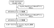
- FIG. 4 is a diagram illustrating the procedure for producing mesoporous alumina (121_MAl_3) supporting Cs 2 CO 3 in an experimental example.
- FIG. 5 is a graph showing the CO2 adsorption isotherm per gram of Cs2CO3 - supported mesoporous alumina in an experimental example.
- FIG. 6 is a diagram illustrating the procedure for producing mesoporous alumina (122_MAl_1) supporting Cs 2 CO 3 and Na 2 CO 3 in an experimental example.
- FIG. 7 is a graph showing the PSA measurement results of Experimental Example 3.
- FIG. 8 is a graph showing the PSA measurement results of Experimental Example 4.
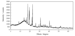
- FIG. 9 is a diagram showing the results of XRD measurement of the adsorbent of Experimental Example 4 before the PSA measurement.
- FIG. 10 is a diagram showing the results of XRD measurement of the adsorbent of Experimental Example 4 after the PSA measurement.
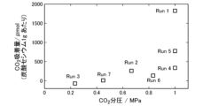
- FIG. 11 is a graph showing the PSA measurement results of Experimental Example 5.
- a carbon dioxide adsorbent (hereinafter also referred to as a " CO2 adsorbent") according to a first embodiment of the present invention has at least one alkali metal element (hereinafter sometimes referred to as a "first alkali metal element") selected from the group consisting of lithium (Li), rubidium (Rb) and cesium (Cs) supported on a carrier.
- first alkali metal element selected from the group consisting of lithium (Li), rubidium (Rb) and cesium (Cs) supported on a carrier.
- Alkali metal elements are metal elements belonging to Group 1 in the periodic table (https://iupac.org/what-we-do/periodic-table-of-elements/), specifically lithium (Li), sodium (Na), potassium (K), rubidium (Rb), cesium (Cs), and francium (Fr).
- the first alkali metal element may be a simple substance or a compound.
- the compound of the first alkali metal element include carbonates, citrates, acetates, nitrates, sulfates, chlorides, oxides, and superoxides. At least one selected from the group consisting of these compounds is preferred, and carbonates are more preferred.
- the first alkali metal element may be an alloy of the first alkali metal elements themselves, or an alloy of the first alkali metal element and a first alkali metal element described below.
- At least one metal element selected from the group consisting of an alkali metal element other than the first alkali metal element (hereinafter also referred to as a "second alkali metal element”), an alkaline earth metal element, and a transition metal element (hereinafter also referred to as a "metal element other than the first alkali metal”) may be supported on the support.
- At least one metal element selected from the group consisting of alkali metal elements, alkaline earth metal elements, Group 13 metal elements, and transition metal elements other than lithium, rubidium, and cesium may be contained in the carrier.
- the above-mentioned metal elements can be added when the adsorbent is manufactured using a compound containing the element as a raw material, but it is also effective to have the element contained in the carrier in advance as a constituent element of the carrier.
- a carrier containing aluminum can be used as the carrier, and the aluminum can be made to be effective in improving the performance of the adsorbent by heat treatment, steam treatment, or heated steam treatment under actual use conditions.
- the second alkali metal element is a metal element other than lithium (Li), rubidium (Rb), and cesium (Cs) among the metal elements belonging to Group 1 in the periodic table (above), and specifically, sodium (Na), potassium (K), and francium (Fr).
- the second alkali metal element is preferably at least one selected from the group consisting of sodium (Na) and potassium (K), and more preferably sodium.
- the alkaline earth metal elements are elements belonging to Group 2 of the periodic table (see above), specifically beryllium (Be), magnesium (Mg), calcium (Ca), strontium (Sr), barium (Ba), and radium (Ra).
- the alkaline earth metal element is preferably at least one selected from the group consisting of magnesium (Mg), calcium (Ca), strontium (Sr), and barium (Ba).
- the alkaline earth metal elements may be used alone or in combination of two or more.
- the Group 13 metal elements are elements belonging to Group 13 in the periodic table (above) whose simple substances have metallic properties (e.g., metallic luster, excellent electrical and thermal conductivity, and tendency to become cations), and specifically include aluminum (Al), gallium (Ga), indium (In), and thallium (Tl).
- the transition metal elements are elements belonging to Groups 3 to 12 of the periodic table (mentioned above), and specifically include scandium (Sc), titanium (Ti), vanadium (V), chromium (Cr), manganese (Mn), iron (Fe), cobalt (Co), nickel (Ni), copper (Cu), zinc (Zn), yttrium (Y), zirconium (Zr), niobium (Nb), molybdenum (Mo), technetium (Tc), ruthenium (Ru), rhodium (Rh), palladium (Pd), silver (Ag), cadmium (Cd), lanthanoids, hafnium (Hf), tantalum (Ta), tungsten (W), rhenium (Re), osmium (Os), iridium (Ir), platinum (Pt), gold (Au), and mercury (Hg).
- the transition metal element is preferably at least one selected from the group consisting of scandium (Sc), yttrium (Y), transition metals in the fourth period of the periodic table (so-called 3d transition metals), among which manganese (Mn), iron (Fe), cobalt (Co), nickel (Ni), zinc (Zn), and lanthanoids.
- the transition metal elements can be used alone or in combination of two or more.
- the lanthanoids are elements with atomic numbers from 57 to 71, i.e., from lanthanum to ruthenium, and specifically include lanthanum (La), cerium (Ce), praseodymium (Pr), neodymium (Nd), promethium (Pm), samarium (Sm), europium (Eu), gadolinium (Gd), terbium (Tb), dysprosium (Dy), holmium (Ho), erbium (Er), thulium (Tm), ytterbium (Yb), and ruthenium (Lu).
- La lanthanum
- Ce cerium
- Pr praseodymium
- Nd neodymium
- Pm promethium
- Sm samarium
- Eu europium
- Gd gadolinium
- Tb terbium
- Dy dysprosium
- Ho holmium
- Er erbium
- the lanthanoid is preferably at least one selected from the group consisting of lanthanum (La), cerium (Ce), neodymium (Nd), samarium (Sm), and ytterbium (Yb).
- the lanthanoid may be used alone or in combination of two or more.
- the alkali metal and other elements supported on the carrier do not adsorb CO2 molecules on the surface, but the entire amount supported undergoes a chemical reaction with CO2. Therefore, in principle, the amount of these elements supported is preferably large, which has a significant effect on the performance of the adsorbent.
- the amount of alkali metal and other elements supported is preferably 5 to 100, more preferably 20 to 100, and even more preferably 45 to 100, as expressed by [moles of the first alkali metal element / (total moles of the first alkali metal element and metal elements other than the first alkali metal element)] x 100.
- the amount of alkali metal element supported on the carrier is not particularly limited, but the mass of the alkali metal supported in terms of the weight of the corresponding carbonate is preferably 15 to 95 mass%, more preferably 20 to 95 mass%, even more preferably 25 to 90 mass%, even more preferably 35 to 90 mass%, and even more preferably 50 to 90 mass% relative to the total mass of the CO 2 adsorbent.
- the amount of the metal element other than the alkali metal is preferably 3 to 95 mass%, more preferably 5 to 60 mass%, more preferably 8 to 60 mass%, and even more preferably 10 to 60 mass% relative to the total mass of the metal element as the net mass of the metal element.
- the carrier may be formed of a mesoporous material, or may be formed of a metal-containing material that is not a mesoporous material.
- the mesoporous material is a material containing pores with a pore diameter of 2 to 50 nm.
- the mesoporous material may contain pores in this range, and may contain a large amount of pores larger than that.
- Catalyst supports generally manufactured and used for industrial catalysts that is, supports made of metal oxides such as silica, alumina, silica-alumina, zirconia, and titania, generally contain a large amount of pores with a diameter of 50 nm or more (referred to as "macropores").
- These industrial catalyst supports are also suitable for use in the CO 2 adsorbent of this embodiment if the ratio of the total volume of pores with a pore diameter of 2 to 50 nm to the total pore volume is 2% or more, preferably 5% or more, more preferably 10% or more, even more preferably 20% or more, even more preferably 30 % or more, even more preferably 40% or more, even more preferably 50% or more, even more preferably 60% or more, even more preferably 70% or more, and particularly preferably 80% or more.
- the mesoporous material is not particularly limited, but is preferably mesoporous alumina or mesoporous silica, and more preferably mesoporous alumina.
- the average pore size of the pores in the mesoporous material is preferably from 2 to 50 nm, more preferably from 2 to 20 nm, and even more preferably from 2 to 10 nm.
- the average pore diameter is a value obtained by analyzing a nitrogen gas adsorption isotherm by the BJH method (Barrett-Joyner-Halenda method).
- the pore volume of the mesoporous material is preferably from 0.01 to 3.0 cm 3 /g, more preferably from 0.1 to 2.0 cm 3 /g, and even more preferably from 0.2 to 1.5 cm 3 /g.
- the pore volume is a value obtained by measurement using a nitrogen gas adsorption method.
- the specific surface area of the mesoporous material is preferably from 20 to 2000 m 2 /g, more preferably from 50 to 1500 m 2 /g, and even more preferably from 100 to 1200 m 2 /g.
- the specific surface area is a value obtained by measurement using a nitrogen gas adsorption method.
- the mesoporous material can be produced by a conventionally known method.
- mesoporous alumina can be produced by mixing an ethanol solution of Pluronic P123 with an ethanol solution of aluminum isopropoxide (Al(O-i-Pr) 3 ) to which nitric acid has been added, followed by drying and calcination.
- Al(O-i-Pr) 3 aluminum isopropoxide
- the non-mesoporous metal-containing material is a metal-containing material other than the mesoporous materials described above, for example, a metal-containing material that is not a "porous material having pores with a diameter of 2 to 50 nm.”
- the metal-containing material may be a simple metal, or a compound such as an oxide, nitride, or carbide.
- metal-containing material examples include aluminum, aluminum alloys, and aluminum compounds such as aluminum oxide (alumina).
- an aluminum-containing material that contains boehmite in part is preferable.
- an aluminum-containing material that contains boehmite in at least part is preferable.
- the aluminum-containing material includes aluminum and various aluminum alloys. Boehmite is an aluminum hydrate oxide that is produced by holding aluminum or an aluminum alloy in high-temperature water or pressurized steam.
- the support can be loaded with a metal element such as cesium by, for example, immersing the mesoporous material in an aqueous solution of a salt of the metal element and then drying it.
- a metal element such as cesium
- the CO2 adsorbent of the second embodiment of the present invention is made of a metal-containing material containing 35% by mass or more, preferably 50% by mass or more, of an alkali metal compound.
- the alkali metals are metallic elements belonging to Group 1 in the periodic table (https://iupac.org/what-we-do/periodic-table-of-elements/), specifically lithium (Li), sodium (Na), potassium (K), rubidium (Rb), cesium (Cs), and francium (Fr).
- the alkali metal compounds include, for example, carbonates of alkali metals.
- carbonates means carbonates, bicarbonates, or compounds containing either or both of carbonate ions and bicarbonate ions.
- the carbonates may also contain other anions such as hydroxide ions.
- Examples of the alkali metal carbonates include cesium, rubidium, and sodium carbonates. At least one selected from the group consisting of cesium, rubidium, and sodium carbonates is preferable, at least one selected from the group consisting of cesium and rubidium carbonates is more preferable, and cesium carbonates are even more preferable.
- the alkali metal carbonates contain, as the alkali metal, at least one selected from the group consisting of cesium and rubidium, and at least one selected from the group consisting of lithium, sodium, and potassium.
- the CO 2 adsorbent of the second embodiment of the present invention does not require a carrier, unlike the CO 2 adsorbent of the first embodiment.
- the CO 2 adsorbents of the first and second embodiments of the present invention described above are preferably used in a pressure swing adsorption method.
- the temperature (adsorption/desorption temperature) during adsorption and desorption of CO2 of the CO2 adsorbent of this embodiment is preferably 80°C or higher, more preferably 100°C or higher, even more preferably 120°C or higher, even more preferably 150°C or higher, even more preferably 160°C or higher, even more preferably 170°C or higher, and even more preferably 200°C or higher.
- the upper limit of the adsorption/desorption temperature is not particularly limited, but is preferably 400°C or lower, more preferably 350°C or higher, and even more preferably 300°C or lower.
- FIG. 1 is a diagram for explaining the estimated mechanism of CO 2 adsorption and release by the CO 2 adsorbent of the present invention.
- cesium carbonate cesium carbonate, Cs 2 CO 3
- mesoporous alumina supporting cesium carbonate Cs 2 CO 3
- water vapor in the mixed gas is condensed to produce water, and Cs 2 CO 3 dissolves in the water to form a Cs 2 CO 3 aqueous solution.
- the compound supported on the adsorbent may be any compound that is converted to carbonates under the adsorption reaction conditions of the adsorbent, and includes carbonates, bicarbonates, compounds containing carbonate ions or bicarbonate ions, and hydroxides. On the other hand, there may also be a mechanism in which carbonates remain solid and adsorb (or absorb) and desorb CO2 without condensing and evaporating water as shown in Figure 1.
- the carbon dioxide adsorbent of the present invention has the following characteristics (A) to (E).
- B) This control of the water vapor partial pressure is achieved by introducing water vapor from the shift reactor into the PSA adsorption tower without intentionally removing it.
- CO2 can be captured by only slightly lowering the pressure (releasing the pressure) without changing the temperature, so the energy required for capture can be significantly reduced compared to conventional methods.
- the carbon dioxide separation method of the present invention is a pressure swing adsorption method for separating carbon dioxide from a mixed gas containing carbon dioxide and water vapor, characterized in that a gas containing water vapor at a relative pressure of 0.10 or more is introduced into an adsorption tower packed with a carbon dioxide adsorbent.
- the relative pressure of the water vapor is not particularly limited as long as it is 0.10 or more, but is preferably 0.20 or more, and more preferably 0.40 or more.
- the upper limit of the relative pressure of the water vapor is not particularly limited, but is preferably 0.90 or less, and more preferably 0.85 or less.
- the saturated water vapor pressure is 1.15 MPa at 200°C, 3.98 MPa at 250°C, and 16.5 MPa at 350°C.
- the carbon dioxide separation method of this embodiment it is preferable to adsorb carbon dioxide to the carbon dioxide adsorbent under high-temperature, high-pressure water vapor coexistence conditions of a total pressure of 1 MPaG or more, water vapor of 10 vol % or more, and a temperature of 100° C. or more.
- the total pressure is not particularly limited as long as it is 1 MPa or more, but is preferably 1.5 MPaG or more, and more preferably 2.0 MPaG or more.
- the upper limit of the total pressure is not particularly limited, but is preferably 8.0 MPaG or less, and more preferably 3.5 MPaG or less.
- the proportion of water vapor is not particularly limited as long as it is 10% by volume or more, but is preferably 15% by volume or more, and more preferably 20% by volume or more.
- the upper limit of the proportion of water vapor is not particularly limited, but is preferably 90% by volume or less, and more preferably 70% by volume or less.
- the temperature is not particularly limited as long as it is 100° C. or higher, but is more preferably 120° C. or higher, even more preferably 150° C. or higher, even more preferably 160° C. or higher, even more preferably 170° C. or higher, and even more preferably 200° C. or higher.
- the upper limit of the temperature is not particularly limited, but is preferably 400° C. or lower, more preferably 350° C. or lower, and even more preferably 300° C. or lower.
- the carbon dioxide adsorbent used in the carbon dioxide separation method of this embodiment is preferably a carbon dioxide adsorbent that has the characteristic that the amount of carbon dioxide adsorbed increases in the presence of water vapor, and the carbon dioxide adsorbents described above are more preferable.
- the carbon dioxide capture and storage plant of this embodiment shown in FIG. 2 includes a gasification facility 11 that gasifies hydrocarbon fuels such as coal, natural gas, and biomass to produce a synthesis gas containing CO and H 2 , a gas purification facility 12 that purifies the synthesis gas containing carbon monoxide and hydrogen produced in the gasification facility 11 to remove sulfur, soot, and the like, a shift reaction facility 13 that subjects the purified synthesis gas to a water-gas shift reaction to produce a mixed gas containing CO 2 , H 2 , and water vapor, a pressure swing adsorption type CO 2 separation and capture facility 16 that separates and captures CO 2 , H 2 , and hydrogen-rich gas (H 2- rich gas) containing water vapor from the mixed gas, a combined cycle power generation facility 14 to which the H 2-rich gas at a pressure of 2.5 to 8.0 MPaG and 150 to 300 ° C. derived from the pressure swing adsorption type CO 2 separation and capture
- the gasification facility 11 includes a gasifier that gasifies hydrocarbon fuels such as coal, natural gas, and biomass.
- hydrocarbon fuels such as coal, natural gas, and biomass.
- To gasify coal in the gasifier for example, the coal is first crushed and dried in a coal pulverizer and then fed into the gasifier together with an oxidizing agent.
- high-temperature combustible gas synthetic gas
- Fluidized bed gasification is a method of gasification using relatively coarse particles with a particle size of a few mm, which are partially burned while fluidizing with air or other fluids. Since combustion occurs at a relatively low temperature of around 1000°C, it is suitable for coal with a high ash melting point, as well as low-grade coal such as high-ash coal. In addition, since it can handle coarse particles, it is also effective for utilizing waste and biomass.
- Entrained flow gasifiers use fine particles with a particle size of 0.1 mm or less, and perform partial combustion at a high temperature of about 1800°C.
- the small particle size results in a large specific surface area, and the high temperature results in an extremely fast reaction rate.
- the design of the gasifier is based on the cube law, so it is compact and can produce large output, making it very economical.
- Coal can be supplied in two ways: dry (dry feed) and wet (slurry feed). In the case of the wet method, coal is mixed with water to form a slurry and then fed to the gasifier, which can be sent through a pipeline.
- the gasification agent can be oxygen (oxygen blown) or air (air blown).
- Oxygen blown is suitable for hydrogen production because it does not contain nitrogen in the generated gas.
- the power required for the air separation unit (ASU) to produce oxygen as a gasification agent is large, which reduces the efficiency of the power plant. Therefore, air blown is more efficient in the case of an integrated coal gasification combined cycle (IGCC) for power generation.
- IGCC integrated coal gasification combined cycle
- the gas purification facility 12 includes a gas-gas heater 121 , a water washing tower 122 , a COS converter 123 , and a desulfurization device 124 .
- the synthesis gas generated in the gasification facility 11 is mainly composed of CO and H2 , but also contains impurities such as nitrogen compounds ( NH3 ) and sulfur compounds ( H2S and COS), which are removed in the gas purification facility 12.
- impurities such as nitrogen compounds ( NH3 ) and sulfur compounds ( H2S and COS)
- the sulfur compounds in the synthesis gas are mainly H2S (hydrogen sulfide) and COS (carbonyl sulfide)
- COS is converted to H2S by a catalytic reaction in the COS converter 123 so that it can be absorbed in an amine aqueous solution.
- the desulfurization device 124 the synthesis gas is passed through an amine aqueous solution to absorb the H2S and remove the sulfur.
- H 2 O water vapor
- a catalyst such as a transition metal oxide such as iron oxide (Fe 3 O 4 (magnetite)) or platinum
- H 2 O water vapor
- the mixed gas containing CO 2 , H 2 and water vapor generated in the shift reaction equipment 13 has a temperature of about 200 to 350°C and a pressure of about 2.5 to 3.5 MPaG.
- the mixed gas is introduced into the pressure swing adsorption type CO 2 separation and capture equipment 16 in a high-temperature and high-pressure state without being subjected to cooling and pressure reduction operations.
- the pressure swing adsorption CO 2 separation and capture equipment 16 includes a pressure swing adsorption CO 2 separation device.
- This pressure swing adsorption CO 2 separation device has an adsorption tower filled with the carbon dioxide adsorbent described above.
- the pressure of the CO 2 extracted from the pressure swing adsorption type CO 2 separation and capture equipment 16 to be supplied to the next process in which the CO 2 is utilized or transported is not particularly limited, but is preferably set to 0.5 to 1.0 MPaG.
- the carbon dioxide capture and storage plant of this embodiment may further include a CO2 liquefaction facility 17 that liquefies the CO2 derived from the pressure swing adsorption CO2 separation and capture facility 16.
- a CO2 liquefaction facility 17 that liquefies the CO2 derived from the pressure swing adsorption CO2 separation and capture facility 16.
- the H2- rich gas separated in the pressure swing adsorption CO2 separation and capture equipment 16 is partially used in the shift reaction equipment 13, and the rest is heated to 300 to 350°C by heat generated in the shift reaction equipment 13, and then supplied to the combined cycle power generation equipment 14, and used as the driving force for the gas turbine 141, and the heat is recovered to the maximum extent in the heat recovery boiler 142 (HRSG: Heat Recovery Steam Generator). This heat is recovered as steam and becomes the power source for the steam turbine 143.
- the exhaust gas from the heat recovery boiler 142 is discharged from the chimney 15.
- the pressure of the CO2 extracted from the pressure swing adsorption CO2 separation and capture equipment 16 that is supplied to the next process in which the CO2 is utilized or transported is set to 0.5 to 1.0 MPaG, so that the CO2 can be supplied to the next process without being further compressed, making it possible to omit part of the compression process.
- Example 1 The manufacturing procedure for the support mesoporous alumina (121_MAl) is shown in FIG. 3, and the manufacturing procedure for the support mesoporous alumina (121_MAl_3) carrying Cs 2 CO 3 is shown in FIG.
- Pore volume per 1 g of MPA: 0.05553/0.4003 0.1387 cm 3 /g
- Reduction in pore volume per MPA: 0.2789-0.1387 0.1402 cm 3 /g
- the decrease in pore volume is due to the loading of Cs2CO3 , and based on the density of Cs2CO3 being 4.072 g/ cm3
- per 1 g of MPA (intrapore Cs2CO3 ) is 1.752 mmol; (external pore Cs2CO3 ) is 2.846 mmol; per 1 g of adsorbent, ( intrapore Cs2CO3 ) is 0.
- the CO2 adsorption amount of 121_MAl_3 was measured using a PSA apparatus.
- the CO2 adsorption isotherm per gram of adsorbent for the 121_MAl_3 sample is shown in Figure 5.
- the plot of the adsorption isotherm is shown as a solid line.
- Run 19 was the first measurement performed with an adsorption time of 600 seconds, but the result showed that the amount of adsorption was not very large. Therefore, the adsorption time was extended to 3600 seconds, and the amount of adsorption increased (Run 20). After that, the adsorption time was returned to 600 seconds and measurements were taken in the areas with low CO2 partial pressure (Runs 21 and 22). The results showed that the amount of adsorption was greater than that of Run 19, which had a high CO2 partial pressure at the same 600 seconds.
- the adsorption amount was measured again at an adsorption time of 600 seconds and a CO2 partial pressure of 1 MPaG, and was found to be the same as that in Run 20 where the adsorption time was 3600 seconds (Run 24). From this result, it is possible that the sample was changed by being exposed to the high-temperature steam in the adsorption gas.
- the reason for the increase in the adsorption amount is that Cs2CO3 , which was supported outside the pores, was taken into the pores and began to contribute to adsorption. It is also possible that aluminum, a constituent element of the alumina support, was added to the supported compound by heat treatment and steam treatment, improving the performance of the adsorbent.
- a large change in adsorption amount of 0.5 mol/kg is obtained with a narrow pressure change of 0.8 MPaG upper limit and 0.6 MPaG lower limit.
- An S-shaped adsorption isotherm that obtains a large change in adsorption amount with a small pressure change is ideal, but this was previously impossible.
- the CO2 partial pressure on the horizontal axis is gauge pressure (MPaG).
- the adsorption amount measured under the same conditions as Run 24 except without water vapor was about 0.2 mmol per 1 g of adsorbent, and the adsorption amount was significantly lower when there was no water vapor than when there was water vapor (Run 24).
- Table 1 shows the amount of Cs 2 CO 3 adsorbed per gram of MPA in Runs 19 and 20 and the amount of Cs 2 CO 3 inside and outside the pores of the samples.
- the pore diameter, pore volume, and BET specific surface area of 122_MAl and 122_MAl_1 are shown in Table 2.
- the pore volume in Table 2 is the value per gram of adsorbent.
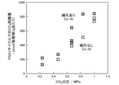
- Example 3 A comparison of CO 2 adsorption performance was carried out using an alumina carrier having pores (with pores) and an alumina carrier without pores (without pores) as the carrier.
- the alumina carriers having the characteristics shown in Table 3 were used, and PSA measurements were carried out in the same manner as in Experimental Example 1.
- the PSA measurement results are shown in FIG.
- the alumina carrier with pores (with pores) and the alumina carrier without pores (without pores) showed almost the same CO2 adsorption performance at the maximum adsorption amount.
- the dependence of the CO2 adsorption amount on the CO2 partial pressure changed depending on the presence or absence of pores.
- Cesium carbonate is thought to adsorb CO2 through the following reaction: Cs2CO3 + H2O + CO2 ⁇ 2CsHCO3 Since 1 g of cesium carbonate is 3069 ⁇ mol, the reaction rate of Cs 2 CO 3 in Run 1 was 59%.
- FIG. 9 shows the XRD measurement results of the adsorbent before the PSA measurement
- FIG. 10 shows the XRD measurement results after the PSA measurement.
- Cs2CO3 showed different peaks before and after PSA measurement.
- Cs2CO3 cesium carbonate
- the gas was adsorbed at a total pressure of 3.0 MPaG for 600 seconds at a temperature of 200°C, and then the total pressure was reduced to 0.3 MPaG, and the amount of CO2 desorbed from the adsorbent was quantified. This operation was repeated 12 times to determine the amount of adsorption per 1 g of adsorbent, and the results shown in Table 4 were obtained. From this result, it was found that cesium carbonate itself had a sufficient amount of adsorption.
- CsHCO 3 cesium hydrogen carbonate
- Gasification equipment 12 Gas purification equipment 121: Gas gas heater 122: Water washing tower 123: COS converter 124: Desulfurization equipment 13: Shift reaction equipment 14: Combined cycle power generation equipment 141: Gas turbine 142: Exhaust heat recovery boiler 143: Steam turbine 15: Chimney 16: Pressure swing adsorption type CO2 separation and recovery equipment 17: CO2 liquefaction equipment 20: Compressor
Abstract
L'invention concerne un adsorbant de dioxyde de carbone dans lequel au moins un élément de métal alcalin choisi dans le groupe constitué par le lithium, le rubidium et le césium est porté par un support. L'adsorbant de dioxyde de carbone peut être utilisé dans un procédé d'isolement de CO2 à variation de pression à haute température dans un processus de gazéification d'hydrocarbures.
Applications Claiming Priority (2)
| Application Number | Priority Date | Filing Date | Title |
|---|---|---|---|
| JP2022164639 | 2022-10-13 | ||
| JP2022-164639 | 2022-10-13 |
Publications (1)
| Publication Number | Publication Date |
|---|---|
| WO2024080190A1 true WO2024080190A1 (fr) | 2024-04-18 |
Family
ID=90669184
Family Applications (1)
| Application Number | Title | Priority Date | Filing Date |
|---|---|---|---|
| PCT/JP2023/036060 WO2024080190A1 (fr) | 2022-10-13 | 2023-10-03 | Adsorbant de dioxyde de carbone, utilisation d'adsorbant de dioxyde de carbone, procédé d'isolation de dioxyde de carbone, installation de récupération/réservation de dioxyde de carbone, et procédé de récupération/réservation de dioxyde de carbone |
Country Status (1)
| Country | Link |
|---|---|
| WO (1) | WO2024080190A1 (fr) |
Citations (7)
| Publication number | Priority date | Publication date | Assignee | Title |
|---|---|---|---|---|
| US5917136A (en) * | 1995-10-04 | 1999-06-29 | Air Products And Chemicals, Inc. | Carbon dioxide pressure swing adsorption process using modified alumina adsorbents |
| JP2001070726A (ja) * | 1999-08-06 | 2001-03-21 | Air Prod And Chem Inc | 二酸化炭素吸着方法、二酸化炭素吸着剤及びその製法 |
| JP2005040753A (ja) * | 2003-07-25 | 2005-02-17 | Shikoku Res Inst Inc | 二酸化炭素吸着剤 |
| JP2009106812A (ja) * | 2007-10-26 | 2009-05-21 | Toshiba Corp | 炭酸ガス吸収材、炭酸ガス分離装置、改質装置、およびこの炭酸ガス吸収材の製造方法 |
| JP2016059917A (ja) * | 2014-09-14 | 2016-04-25 | 国立大学法人 千葉大学 | 二酸化炭素回収材、二酸化炭素回収材の生産方法及び二酸化炭素の回収方法 |
| US20210187480A1 (en) * | 2017-11-10 | 2021-06-24 | Climeworks Ag | Materials for the direct capture of carbon dioxide from atmospheric air |
| US20220267147A1 (en) * | 2021-02-22 | 2022-08-25 | Fluor Technologies Corporation | Gas reformer for producing hydrogen |
-
2023
- 2023-10-03 WO PCT/JP2023/036060 patent/WO2024080190A1/fr unknown
Patent Citations (7)
| Publication number | Priority date | Publication date | Assignee | Title |
|---|---|---|---|---|
| US5917136A (en) * | 1995-10-04 | 1999-06-29 | Air Products And Chemicals, Inc. | Carbon dioxide pressure swing adsorption process using modified alumina adsorbents |
| JP2001070726A (ja) * | 1999-08-06 | 2001-03-21 | Air Prod And Chem Inc | 二酸化炭素吸着方法、二酸化炭素吸着剤及びその製法 |
| JP2005040753A (ja) * | 2003-07-25 | 2005-02-17 | Shikoku Res Inst Inc | 二酸化炭素吸着剤 |
| JP2009106812A (ja) * | 2007-10-26 | 2009-05-21 | Toshiba Corp | 炭酸ガス吸収材、炭酸ガス分離装置、改質装置、およびこの炭酸ガス吸収材の製造方法 |
| JP2016059917A (ja) * | 2014-09-14 | 2016-04-25 | 国立大学法人 千葉大学 | 二酸化炭素回収材、二酸化炭素回収材の生産方法及び二酸化炭素の回収方法 |
| US20210187480A1 (en) * | 2017-11-10 | 2021-06-24 | Climeworks Ag | Materials for the direct capture of carbon dioxide from atmospheric air |
| US20220267147A1 (en) * | 2021-02-22 | 2022-08-25 | Fluor Technologies Corporation | Gas reformer for producing hydrogen |
Similar Documents
| Publication | Publication Date | Title |
|---|---|---|
| Wang et al. | A review of CO2 sorbents for promoting hydrogen production in the sorption-enhanced steam reforming process | |
| Chen et al. | Recent progress in integrated CO2 capture and conversion process using dual function materials: a state-of-the-art review | |
| Gao et al. | A review of recent developments in hydrogen production via biogas dry reforming | |
| US7618606B2 (en) | Separation of carbon dioxide (CO2) from gas mixtures | |
| Jo et al. | CO 2 green technologies in CO 2 capture and direct utilization processes: methanation, reverse water-gas shift, and dry reforming of methane | |
| Buckingham et al. | Recent advances in carbon dioxide capture for process intensification | |
| KR102622341B1 (ko) | 이산화탄소 포집과 수소생산 동시 수행을 위한 수소분리/이산화탄소 흡수 하이브리드 장치 및 공정 | |
| Zhang et al. | Hydrogen production via steam reforming of coke oven gas enhanced by steel slag-derived CaO | |
| RU2509720C2 (ru) | Способ получения водорода с полным улавливанием co2 и рециклом непрореагировавшего метана | |
| CN102264633A (zh) | 水煤气变换方法 | |
| CA2860684A1 (fr) | Production d'hydrogene haute pression haute purete avec capture sur place de co2 et de soufre dans un reacteur a une seule etape | |
| AU2013200891A1 (en) | Method of gas purification, coal gasification plant, and shift catalyst | |
| WO2007002882A2 (fr) | Regeneration de sulfure de calcium en carbonate de calcium mesoporeux utilisant des dispersants ioniques et la recuperation selective | |
| WO2019073867A1 (fr) | Système de production de méthane | |
| Sun et al. | Sorption enhanced coal gasification for hydrogen production using a synthesized CaOMgO-molecular sieve sorbent | |
| Jo et al. | A fundamental study of CO2 capture and CH4 production in a rapid cyclic system using nickel-lithium-silicate as a catal-sorbent | |
| Zhang et al. | Role and mechanism of calcium-based catalysts for methane dry reforming: A review | |
| Rahim et al. | Review of high temperature H2S removal from syngas: Perspectives on downstream process integration | |
| JP2017521353A (ja) | 水素を生成するための方法 | |
| KR102438075B1 (ko) | 이중 기능 촉매-흡수제를 이용한 이산화탄소 포집 및 직접 활용 공정 | |
| Zang et al. | Strategies to improve CaO absorption cycle stability and progress of catalysts in Ca-based DFMs for integrated CO2 capture-conversion: A critical review | |
| WO2021186658A1 (fr) | Système de production de méthanol et procédé de production de méthanol | |
| WO2024080190A1 (fr) | Adsorbant de dioxyde de carbone, utilisation d'adsorbant de dioxyde de carbone, procédé d'isolation de dioxyde de carbone, installation de récupération/réservation de dioxyde de carbone, et procédé de récupération/réservation de dioxyde de carbone | |
| JP2005041749A (ja) | Coシフト反応の促進方法及びそれを利用した水素ガス又はco含有率の低減されたガスの製造方法 | |
| WO2017183388A1 (fr) | Moteur à combustion interne |