WO2024075836A1 - 経路設定装置および経路設定方法 - Google Patents
経路設定装置および経路設定方法 Download PDFInfo
- Publication number
- WO2024075836A1 WO2024075836A1 PCT/JP2023/036530 JP2023036530W WO2024075836A1 WO 2024075836 A1 WO2024075836 A1 WO 2024075836A1 JP 2023036530 W JP2023036530 W JP 2023036530W WO 2024075836 A1 WO2024075836 A1 WO 2024075836A1
- Authority
- WO
- WIPO (PCT)
- Prior art keywords
- route
- target
- state
- information
- unit
- Prior art date
- Legal status (The legal status is an assumption and is not a legal conclusion. Google has not performed a legal analysis and makes no representation as to the accuracy of the status listed.)
- Ceased
Links
Images





Classifications
-
- G—PHYSICS
- G01—MEASURING; TESTING
- G01C—MEASURING DISTANCES, LEVELS OR BEARINGS; SURVEYING; NAVIGATION; GYROSCOPIC INSTRUMENTS; PHOTOGRAMMETRY OR VIDEOGRAMMETRY
- G01C21/00—Navigation; Navigational instruments not provided for in groups G01C1/00 - G01C19/00
- G01C21/26—Navigation; Navigational instruments not provided for in groups G01C1/00 - G01C19/00 specially adapted for navigation in a road network
- G01C21/34—Route searching; Route guidance
-
- G—PHYSICS
- G08—SIGNALLING
- G08G—TRAFFIC CONTROL SYSTEMS
- G08G1/00—Traffic control systems for road vehicles
-
- G—PHYSICS
- G08—SIGNALLING
- G08G—TRAFFIC CONTROL SYSTEMS
- G08G1/00—Traffic control systems for road vehicles
- G08G1/09—Arrangements for giving variable traffic instructions
Definitions
- This disclosure relates to a route setting device and a route setting method.
- Technology for patrolling and monitoring a predetermined route is known. For example, technology has been disclosed that acquires recording information at a planned frequency in a patrol area, making it less likely that recording will be missed (see Patent Document 1). Also, technology has been disclosed that detects the occurrence of landslides from images captured by a terminal device installed in a location where there is a high risk of landslides (see Patent Document 2).
- patrol cars and other vehicles are used to patrol and monitor areas at risk of land disasters such as cliff collapses, and landslide hazard zones.
- land disasters such as cliff collapses, and landslide hazard zones.
- there may be multiple landslide hazard zones over a wide area and monitoring areas with a low risk of cliff collapses and other disasters is not carried out due to limitations on the number of vehicles that can be deployed.
- the present disclosure aims to provide a route setting device and a route setting method that can appropriately set a patrol route for monitoring a monitoring target.
- the route setting device disclosed herein includes an acquisition unit that acquires information indicating the state of an object acquired by a first device mounted on a first moving body, and a setting unit that sets a route along which a second moving body equipped with a second device capable of acquiring more information than the first device will travel, based on the information indicating the state of the object.
- the route setting device disclosed herein includes an acquisition unit that acquires information indicating the state of an object acquired by a first device mounted on a first moving body, and a setting unit that sets a route along which a second moving body mounted with a second device that has a larger movable area than the first device will travel, based on the information indicating the state of the object.
- the route setting method disclosed herein acquires information indicating the state of an object acquired by a first device mounted on a first moving body, and sets a route for a second moving body equipped with a second device capable of acquiring more information than the first device based on the information indicating the state of the object.
- the route setting method disclosed herein acquires information indicating the state of an object acquired by a first device mounted on a first moving body, and sets a route for a second moving body mounted with a second device having a larger movable area than the first device to travel based on the information indicating the state of the object.
- FIG. 1 is a block diagram showing an example of the configuration of a route setting system according to the first embodiment.
- FIG. 2 is a diagram showing an overview of the route setting system according to the first embodiment.
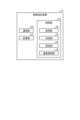
- FIG. 3 is a block diagram illustrating an example of the configuration of the route setting device according to the first embodiment.
- FIG. 4 is a block diagram illustrating an example of the configuration of the first device according to the first embodiment.
- FIG. 5 is a block diagram illustrating an example of the configuration of the second device according to the first embodiment.
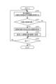
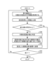
- FIG. 6 is a flowchart showing the process of the route setting device according to the first embodiment.
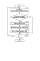
- FIG. 7 is a flowchart showing the process of the route setting device according to the first modified example of the first embodiment.
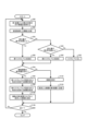
- FIG. 8 is a flowchart showing the process of the route setting device according to the second modified example of the first embodiment.
- FIG. 9 is a diagram for explaining an overview of a route setting system according to the second embodiment.
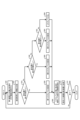
- FIG. 10 is a flowchart showing the process of the route setting device according to the second embodiment.
- FIG. 11 is a flowchart showing the process of the route setting device according to the third embodiment.
- FIG. 12 is a flowchart showing the process of the route setting device according to the fourth embodiment.
- FIG. 13 is a flowchart showing the process of the route setting device according to the fifth embodiment.
- FIG. 1 is a block diagram showing a configuration example of the route setting system according to the first embodiment.
- Fig. 2 is a diagram showing an overview of the route setting system according to the first embodiment.
- the route setting system 1 includes a route setting device 10, a plurality of first devices 12, and a second device 14.
- the route setting device 10 is communicatively connected to the first devices 12 and the second devices 14 via a network N.
- the first devices 12 are devices mounted on a first moving body.
- the second devices 14 are devices mounted on a second moving body.
- the route setting device 10 is a device that appropriately sets a travel route along which the second moving body should travel, based on information indicating the state of an object acquired by the first device mounted on the first moving body.
- the first moving body may be a dedicated vehicle that travels along a predetermined circular route, or a commercial vehicle such as a bus or delivery vehicle that travels along a predetermined route. It may also be a general vehicle that travels at the driver's discretion without a set route.
- the second moving body is a dedicated vehicle that travels along a travel route set by the route setting device 10.
- Figure 2 shows an overview of the route setting system 1 according to the first embodiment.
- Figure 2 shows general vehicles 2-1 to 2-n (n is an integer equal to or greater than 2) and a dedicated vehicle 3. When it is not necessary to distinguish between the general vehicle 2-1, it is collectively referred to as the general vehicle 2.
- the first moving body is the general vehicle 2, and the second moving body is the dedicated vehicle 3.
- the general vehicle 2 is equipped with the first device 12.
- the general vehicle 2 may be, for example, a private car owned by a general user.
- the general vehicle 2 may be, for example, a commercial vehicle such as a bus or a delivery vehicle.
- the general vehicle 2 is a type of first moving body.
- the first route R1 may be a predetermined route or a free route driven by the driver's will.
- the routes driven by the general vehicles 2-1 to 2-n within a predetermined time are respectively the first routes R1-1 to R1-n.
- the first device 12 mounted on each of the general vehicles 2-1 to 2-n detects the state of the object present near the moving route.
- the object is an object or object that indicates a risk of disaster occurrence, or an object or object that indicates a precursor of a disaster.
- the object is a mountain slope (cliff) that is at risk of landslide, a river that is at risk of flooding, a coast that is at risk of tsunami occurrence, etc.
- the object is a structure such as a bridge or embankment, or a tree that may lean as a precursor of a landslide.
- the target location is a cliff and the vehicle patrols multiple cliffs.
- the patrol does not only detect the state of the same type of object, but may also detect the state of different objects that indicate a precursor of the same type of disaster or objects that indicate a precursor of different types of disasters.
- the first device 12 transmits the object detection result to the route setting device 10.
- the object for which the general vehicle 2 detects the state is not limited to one location or one object.
- the state of multiple objects that exist near the travel route may be detected.
- the general vehicle 2 detects the state of all objects that exist near the travel route.
- the general vehicle 2 detects the state of some of the objects that exist near the travel route.
- detecting the state of the object means acquiring information that indicates the state of the object, such as an image or sound of the object or the target location.
- the dedicated vehicle 3 is equipped with the second device 14.
- the dedicated vehicle 3 may be a patrol car that drives while monitoring the target of monitoring.
- the dedicated vehicle 3 may be a vehicle driven by a person or an autonomous vehicle.
- the dedicated vehicle 3 is a type of second moving body.
- the dedicated vehicle 3 patrols the second route R2 while detecting the state of the monitored target with the second device 14.
- the second route R2 is a route that is set to patrol points with a high risk of cliff collapse based on a hazard map provided by a local government, public institution, etc., for example.
- the second device 14 can obtain information indicating the state of more targets than the first device 12. That is, the second device 14 can grasp the state of the target with higher accuracy than the first device 12. Details of the first device 12 and the second device 14 will be described later.
- the route setting device 10 receives target detection results from multiple first devices 12. When the route setting device 10 determines that the target is a monitoring target based on the target detection results, it sets a second route R2 so that the target determined to be a monitoring target can be monitored. This allows the route setting device 10 to appropriately set a patrol route for monitoring the monitoring target.
- first moving body and the second moving body are described as vehicles, but the present disclosure is not limited thereto.
- the first moving body and the second moving body may be, for example, a drone.
- the first moving body and the second moving body may be, for example, a person carrying a device capable of acquiring information (for example, a camera or a smartphone).
- Fig. 3 is a block diagram showing an example of the configuration of the route setting device according to the first embodiment.
- the route setting device 10 includes a communication unit 20, a storage unit 22, and a control unit 24.
- the route setting device 10 is a device realized by a server device or the like.
- the route setting device 10 is provided as a server device installed in a building, such as within the grounds of a local government.
- the route setting device 10 may be provided as an in-vehicle device in the second mobile body.
- the communication unit 20 is a communication interface that executes communication between the route setting device 10 and an external device.
- the communication unit 20 executes communication between the route setting device 10 and a first device 12, for example.
- the communication unit 20 executes communication between the route setting device 10 and a second device 14, for example.
- the memory unit 22 stores various types of information.
- the memory unit 22 stores information such as the calculation contents of the control unit 24 and programs.
- the memory unit 22 includes at least one of a RAM (Random Access Memory), a main memory such as a ROM (Read Only Memory), and an external memory such as a HDD (Hard Disk Drive).
- a RAM Random Access Memory
- main memory such as a ROM (Read Only Memory)
- HDD Hard Disk Drive
- the storage unit 22 may store, for example, information indicating the state of the target acquired from the first device 12.
- the information indicating the state of the target may be associated with date and time information regarding the date and time when the information on the target was acquired.
- the storage unit 22 may store, for example, a hazard map acquired from the outside.
- the storage unit 22 may store, for example, the second route R2 that the second mobile body patrolled last time, and information indicating the state of the target acquired by the last patrol.
- the control unit 24 controls each part of the route setting device 10.
- the control unit 24 has, for example, an information processing device such as a CPU (Central Processing Unit) or an MPU (Micro Processing Unit), and a storage device such as a RAM or ROM.
- the control unit 24 executes a program that controls the operation of the route setting device 10 according to the present disclosure.
- the control unit 24 may be realized by an integrated circuit such as an ASIC (Application Specific Integrated Circuit) or an FPGA (Field Programmable Gate Array).
- the control unit 24 may be realized by a combination of hardware and software.
- the control unit 24 includes an acquisition unit 30, a determination unit 32, a setting unit 34, and a communication control unit 36.
- the acquisition unit 30 acquires various information from an external device via the communication unit 20.
- the acquisition unit 30 acquires target information from the first device 12 via the communication unit 20.
- the acquisition unit 30 may also acquire information indicating the target state from the second device 14 via the communication unit 20.
- the determination unit 32 determines various information. The determination unit 32 determines whether the target is a monitoring target based on the information of the target acquired by the acquisition unit 30. Specifically, the determination unit 32 determines whether the risk of a cliff collapse is greater than or equal to a predetermined level based on the information of the state of the cliff acquired by the acquisition unit 30. For example, the determination unit 32 determines that the risk of a cliff collapse is greater than or equal to a predetermined level when a state such as a crack in the cliff, water gushing from the cliff, or small stones falling from the cliff is detected based on an image of the cliff. For example, a known moving object detection technology may be used to detect a predetermined state from the captured image, similar to the method described in Patent Document 3.
- the determination unit 32 determines whether the risk of a cliff collapse is greater than or equal to a predetermined level when a mountain rumble is detected based on a sound detected around the cliff.
- the determination unit 32 determines that the target is a monitoring target when a specific event is included in the state of the target acquired by the acquisition unit 30.
- the determination unit 32 may, for example, determine whether or not a target at a certain location is a monitoring target based on the previously acquired information and the currently acquired information. The determination unit 32 may, for example, determine that the target is a monitoring target when the amount of change between the previously acquired information and the currently acquired information is greater than or equal to a predetermined amount. The determination unit 32 may, for example, determine that the target is a monitoring target when the amount of change per unit of time between the previously acquired information and the currently acquired information is greater than or equal to a predetermined amount. Note that the method of determining the risk of a cliff collapse can be any known method, and is not limited to these. The determination unit 32 may set multiple risk levels and determine the risk level of the target.
- the determination unit 32 determines the risk level according to the type of event included in the state of the target acquired by the acquisition unit 30. For example, the determination unit 32 determines the risk level of the target according to the amount of change between the previously acquired information and the currently acquired information. For example, the determination unit 32 determines the risk level of the target according to the amount of change per unit of time between the previously acquired information and the currently acquired information.
- the risk level of the target may be set in multiple stages, such as "high”, “medium”, and "low", or may be set numerically.
- the setting unit 34 sets the route along which the dedicated vehicle 3 equipped with the second device 14 should travel. Specifically, the setting unit 34 sets the route along which the dedicated vehicle 3 should travel so as to include the location where the first device 12 has acquired information on the target determined by the determination unit 32 to be a monitoring target. For example, the setting unit 34 refers to the hazard map stored in the memory unit 22 and sets the route along which the dedicated vehicle 3 should travel so as to include the location where the first device 12 has acquired information on the target determined to be a monitoring target.
- the setting unit 34 refers to the second route R2 that the second moving body previously patrolled and that is stored in the memory unit 22 and sets the route along which the dedicated vehicle 3 should travel so as to include the location where the first device 12 has acquired information on the target determined to be a monitoring target.
- the determination unit 32 sets multiple risk levels
- the setting unit 34 sets the route along which the dedicated vehicle 3 should travel so as to preferentially patrol the location where the first device 12 has acquired information on the target determined to be a high risk.
- the setting unit 34 sets the route so that the vehicle travels through points determined by the determination unit 32 to have a "high” risk level, then travels through points determined to have a "medium” risk level, and then travels through points determined to have a "low” risk level.
- the communication control unit 36 controls the communication unit 20 to control the transmission and reception of information between the route setting device 10 and external devices.
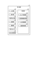
- Fig. 4 is a block diagram showing an example of the configuration of the first device according to the first embodiment.
- the first device 12 includes an input unit 40, a display unit 42, an audio output unit 44, a memory unit 46, a communication unit 48, a first sensor 50, a GNSS (Global Navigation Satellite System) receiving unit 52, and a control unit 54.
- the first device 12 is realized, for example, by a drive recorder.
- the input unit 40 accepts various operations for the first device 12.
- the input unit 40 is realized by a switch, a button, a touch panel, etc.
- the display unit 42 displays various images.
- the display unit 42 is, for example, a display including a liquid crystal display, an organic EL (Electro-Luminescence), etc.
- the audio output unit 44 is a speaker that outputs various sounds.
- the memory unit 46 stores various types of information.
- the memory unit 46 stores information such as the contents of calculations performed by the control unit 54 and programs.
- the memory unit 46 includes at least one of, for example, a RAM, a main storage device such as a ROM, and an external storage device such as a HDD.
- the communication unit 48 is a communication interface that performs communication between the first device 12 and an external device.
- the communication unit 48 performs communication between the first device 12 and the route setting device 10, for example.
- the first sensor 50 detects the state of an object in the vicinity of the general vehicle 2 in which the first device 12 is mounted.
- the first sensor 50 is realized, for example, by a camera and a microphone.
- the first sensor 50 captures, for example, an image of the state of the target cliff.
- the first sensor 50 detects, for example, sound around the target cliff. If the first sensor 50 is, for example, a camera and a microphone, it functions as a drive recorder that acquires images and sound around the vehicle.
- the GNSS receiving unit 52 is composed of a GNSS receiver that receives GNSS signals from GNSS satellites.
- the GNSS receiving unit 52 outputs the received GNSS signals to the position information acquisition unit 62.
- the control unit 54 controls each part of the first device 12.
- the control unit 54 has, for example, an information processing device such as a CPU or MPU, and a storage device such as a RAM or ROM.
- the control unit 54 executes a program that controls the operation of the first device 12 according to the present disclosure.
- the control unit 54 may be realized, for example, by an integrated circuit such as an ASIC or FPGA.
- the control unit 54 may be realized by a combination of hardware and software.
- the control unit 54 includes a sensor control unit 60, a location information acquisition unit 62, an output control unit 64, and a communication control unit 66.
- the sensor control unit 60 controls the first sensor 50 to detect the state of an object in the vicinity of the general vehicle 2 on which the first device 12 is mounted.
- the sensor control unit 60 acquires information indicating the state of the object from the first sensor 50. If the first sensor 50 is a camera, it acquires an image of the object as information indicating the state of the object. If the first sensor 50 is a microphone, it acquires sound emitted by the object and sound around the object as information indicating the state of the object.
- the location information acquisition unit 62 acquires current location information of the general vehicle 2 on which the first device 12 is mounted.
- the location information acquisition unit 62 acquires current location information of the general vehicle 2 based on the GNSS signal received by the GNSS receiver unit 52.
- the location information acquisition unit 62 acquires, for example, location information of the point where the first sensor 50 acquired information of the target based on the GNSS signal received by the GNSS receiver unit 52 as the target location information.
- the output control unit 64 controls the display unit 42 to display various images.
- the output control unit 64 controls the audio output unit 44 to output various sounds.
- the communication control unit 66 controls the communication unit 48 to control the transmission and reception of information between the first device 12 and an external device.
- the communication control unit 66 transmits, for example, information indicating the state of the target detected by the first sensor 50 and the position information of the target to the route setting device 10 via the communication unit 48.
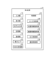
- Fig. 5 is a block diagram showing an example of the configuration of the second device according to the first embodiment.
- the second device 14 includes an input unit 70, a display unit 72, an audio output unit 74, a memory unit 76, a communication unit 78, a second sensor 80, a GNSS receiving unit 82, and a control unit 84.
- the second device 14 is a device that can obtain more information about a target with higher accuracy than the first device 12.
- the input unit 70 accepts various operations for the second device 14.
- the input unit 70 is realized by a switch, a button, a touch panel, etc.
- the display unit 72 displays various images.
- the display unit 72 is, for example, a display including a liquid crystal display, an organic electroluminescence display, etc.
- the audio output unit 74 is a speaker that outputs various sounds.
- the memory unit 76 stores various types of information.
- the memory unit 76 stores information such as the contents of calculations performed by the control unit 84 and programs.
- the memory unit 76 includes at least one of, for example, a RAM, a main memory device such as a ROM, and an external memory device such as a HDD.
- the communication unit 78 is a communication interface that performs communication between the second device 14 and an external device.
- the communication unit 78 performs communication between the second device 14 and the route setting device 10, for example.
- the second sensor 80 detects the state of the object around the dedicated vehicle 3 on which the second device 14 is mounted. If the second sensor 80 is a camera, it is a camera with high detection accuracy, such as a camera with a higher resolution than the first sensor 50 or a camera with a high frame rate. If the second sensor 80 is a microphone, it is a microphone with high detection accuracy, such as a microphone with higher sensitivity than the first sensor 50, or a microphone with a high sampling rate and wide frequency characteristics. In other words, the second sensor 80 is a sensor that detects information on the state of the object with higher detection accuracy than the first sensor, that is, a sensor that acquires a large amount of information. The second sensor 80 may include various sensors such as an ultrasonic sensor and an odor sensor.
- the second sensor 80 may include a sensor that measures a three-dimensional shape based on the reflected light of light irradiated on the object, similar to the method described in Patent Document 4.
- the second sensor 80 also includes a sensor that acquires information on the state of the object different from that of the first sensor 50, that is, a sensor that acquires a large variety of information.
- the second sensor 80 acquires more information than the first sensor 50. If the second sensor 80 is a measuring device such as a range finder, thermometer, or sound level meter, it may obtain information indicating the state of the target in numerical form.
- the GNSS receiving unit 82 is composed of a GNSS receiver that receives GNSS signals from GNSS satellites.
- the GNSS receiving unit 82 outputs the received GNSS signals to the position information acquisition unit 92.
- the control unit 84 controls each part of the second device 14.
- the control unit 84 has, for example, an information processing device such as a CPU or MPU, and a storage device such as a RAM or ROM.
- the control unit 84 executes a program that controls the operation of the second device 14 according to the present disclosure.
- the control unit 84 may be realized, for example, by an integrated circuit such as an ASIC or FPGA.
- the control unit 84 may be realized by a combination of hardware and software.
- the control unit 84 includes a sensor control unit 90, a location information acquisition unit 92, a route information acquisition unit 94, an output control unit 96, and a communication control unit 98.
- the sensor control unit 90 controls the second sensor 80 to detect the state of an object in the vicinity of the dedicated vehicle 3 on which the second device 14 is mounted.
- the sensor control unit 90 acquires information indicating the state of the object from the second sensor 80.
- the location information acquisition unit 92 acquires current location information of the dedicated vehicle 3 on which the second device 14 is mounted.
- the location information acquisition unit 92 acquires current location information of the dedicated vehicle 3 based on the GNSS signal received by the GNSS receiving unit 82.
- the location information acquisition unit 92 acquires, for example, location information of the point where the second sensor 80 acquired information of the target based on the GNSS signal received by the GNSS receiving unit 82 as the target location information.
- the output control unit 96 controls the display unit 72 to display various images.
- the output control unit 96 controls the audio output unit 74 to output various sounds.
- the communication control unit 98 controls the communication unit 78 to control the transmission and reception of information between the second device 14 and an external device.
- the communication control unit 98 transmits, for example, information indicating the state of the target obtained by the second sensor 80 and the position information of the target to the route setting device 10 via the communication unit 78.
- Fig. 6 is a flowchart showing the process contents of the route setting device according to the first embodiment.
- the acquisition unit 30 acquires information indicating the state of the target from the first device 12 (step S10). Specifically, the acquisition unit 30 acquires information indicating the state of the cliff from the first device 12 mounted on the general vehicle 2. The information indicating the target information may include position information of the target. Then, the process proceeds to step S12.
- the determination unit 32 determines whether the target is a monitoring target (step S12). Specifically, the determination unit 32 determines that the target is a monitoring target when the risk of a cliff collapse occurring on the cliff about which information has been acquired is equal to or greater than a predetermined level. If it is determined that the target is a monitoring target (step S12; Yes), the process proceeds to step S14. If it is not determined that the target is a monitoring target (step S12; No), the process proceeds to step S18.
- step S12 returns Yes
- the setting unit 34 sets a route that includes the points to be monitored (step S14). Specifically, the setting unit 34 sets a route that the dedicated vehicle 3 will patrol for monitoring so as to include points where the risk of cliff collapse is equal to or greater than a predetermined level. Then, the process proceeds to step S16.
- the communication control unit 36 transmits information about the route set by the setting unit 34 to the second device 14 (step S16). Then, the process proceeds to step S18.
- the control unit 24 determines whether or not to end the process (step S18). For example, the control unit 24 determines to end the process when the operation of the first device 12 is completed. If it is determined to end the process (step S18; Yes), the process of FIG. 6 ends. If it is not determined to end the process (step S18; No), the process proceeds to step S10.
- the above process is not limited to one location and one object.
- the first device 12 transmits the acquired information to the route setting device 10, and the route setting device 10 performs steps S10 and S12.
- the process may proceed to step S14 each time to set the route, or after steps S10 and S12 are repeated for a predetermined period, the process may proceed to step S14 to set the route based on the information acquired by the first device within the predetermined period.
- the period for repeating steps S10 and S12 is determined as a predetermined time, the time when the general vehicle 2 has traveled a predetermined distance, the time when the general vehicle 2 has traveled a predetermined area, etc.
- the period for repeating steps S10 and S12 may be the period from the end time of the last tour of the dedicated vehicle 3 to the start time of the next tour.
- the process may proceed to step S14 if a risk level equal to or higher than a predetermined level is judged in step S12 even within the predetermined period.
- Step S10 in the above process may acquire information from the first devices 12 in multiple general vehicles 2.
- the first embodiment can set a route for a dedicated vehicle 3 equipped with a second device 14 capable of acquiring more information than the first device 12 to patrol in order to monitor a target, based on information acquired by a first device 12 installed in a general vehicle 2. This allows the first embodiment to appropriately set a patrol route for monitoring a monitoring target.
- the second sensor 80 capable of acquiring information on the state of the target with high accuracy is a high-cost sensor, and the number of second moving bodies equipped with the second sensor 80 is limited.
- the first sensor 50 may be a low-cost sensor, and a large number of first moving bodies equipped with the first sensor 50 can be introduced, or a general vehicle can be used as the first moving body.
- Targets with a high risk of disaster occurrence are set as monitoring targets, and a patrol route for monitoring the monitoring targets can be appropriately set based on information acquired by the first moving body with a limited number of second moving bodies.
- the first embodiment can reduce economic costs.
- the route of the second moving body based on information acquired by multiple first moving bodies traveling on different routes, the route can be appropriately set over a wider range.
- Fig. 7 is a flowchart showing the process contents of the route setting device according to the first modified example of the first embodiment.
- step S30 is the same as the process of step S10 shown in FIG. 6, so a description thereof will be omitted.
- the determination unit 32 compares the information of the target previously acquired by the acquisition unit 30 with the information acquired this time (step S32). For example, the determination unit 32 calculates the amount of change between the previous information of the target and the information of the current target. For example, if the information indicating the state of the target is an image, the image captured last time is compared with the image captured this time. Also, the previously acquired information and the currently acquired information can be compared by generating a difference image between the previously captured image and the currently captured image.
- the previous information of the target and the currently acquired information of the target are not limited to information acquired by the same first moving body.
- the information acquired by the general vehicle 2-1 and the information acquired by the general vehicle 2-n may be compared. If the previous information of the target and the currently acquired information of the target are acquired by different first moving bodies, the performance, installation conditions, etc. of the first sensor 50 provided on each first moving body are different. For example, if the first sensor 50 is a camera and the information indicating the state of the target is an image, the resolution, angle of view, etc. are different. After performing processes such as converting the resolution and adjusting the angle of view, the amount of change is calculated and a difference image is generated. Then, proceed to step S34.
- the determination unit 32 determines whether the amount of change between the previously acquired information of the target and the currently acquired information is greater than or equal to a predetermined amount (step S34). For example, the determination unit 32 determines whether the difference between the previously acquired information of the target and the currently acquired information is greater than or equal to a predetermined amount. For example, the determination unit 32 may determine whether the amount of change per unit of time between the previously acquired information and the currently acquired information is greater than or equal to a predetermined amount.
- the amount of change takes into account the change due to the acquired situation. For example, if the information indicating the state of the target is an image, the brightness of the surroundings changes depending on the time of acquisition, and the brightness of the entire image changes.
- step S34 The amount of brightness change is calculated based on the average brightness of the image, etc., and is subtracted from the amount of change. If it is determined that the amount of change is greater than or equal to a predetermined amount (step S34; Yes), proceed to step S36. If it is not determined that the amount of change is greater than or equal to a predetermined amount (step S34; No), proceed to step S42.
- the determination unit 32 determines that the object with the change amount equal to or greater than a predetermined amount is to be monitored (step S36). Then, the process proceeds to step S38.
- the setting unit 34 sets a route including the locations of the monitoring targets according to the amount of change in the acquired information (step S38). For example, the setting unit 34 sets a route for the dedicated vehicle 3 to patrol for monitoring so that monitoring targets for which the difference between the previously acquired information and the currently acquired information is greater than or equal to a predetermined amount and the difference is large can be monitored with priority. For example, the setting unit 34 sets a route for the dedicated vehicle 3 to patrol for monitoring so that monitoring targets for which the change per unit of time between the previously acquired information and the currently acquired information is greater than or equal to a predetermined amount and the change is large can be monitored with priority. Then, proceed to step S40.
- steps S40 and S42 are the same as those in steps S16 and S18 shown in FIG. 6, and therefore will not be described here.
- the first modified example of the first embodiment can determine that monitoring targets for which there is a large difference between the information previously acquired and the information currently acquired are targets at high risk of disaster occurrence, and set a route for the dedicated vehicle 3 to patrol on a priority basis. This makes it possible for the first modified example of the first embodiment to appropriately set a patrol route for monitoring the monitoring targets.
- a second modified example of the first embodiment will be described.
- a process is executed to determine a risk level of an object, and to set a route for the dedicated vehicle 3 to travel based on the risk level of the object.
- Fig. 8 is a flowchart showing the process contents of the route setting device according to the second modified example of the first embodiment.
- steps S50 and S52 is the same as the processing in steps S30 and S32 shown in FIG. 7, so a description thereof will be omitted.
- the determination unit 32 determines whether the amount of change between the previously acquired information of the target and the currently acquired information is equal to or greater than a first predetermined value (step S54).
- the first predetermined value may be determined in advance. If it is determined that the amount of change is equal to or greater than the first predetermined value (step S54; Yes), the process proceeds to step S56. If it is not determined that the amount of change is equal to or greater than the first predetermined value (step S54; No), the process proceeds to step S58.
- step S54 the judgment unit 32 sets a first risk level for the target (step S56).
- the first risk level is the "high” risk level when the risk of a disaster occurring is divided into three levels: "high,” “medium,” and “low.” Then, the process proceeds to step S68.
- step S58 determines whether the amount of change between the previously acquired information of the target and the currently acquired information is equal to or greater than a second predetermined value and less than a first predetermined value (step S58).
- the second predetermined value may be determined in advance. If it is determined that the amount of change is equal to or greater than the second predetermined value and less than the first predetermined value (step S58; Yes), the process proceeds to step S60. If it is not determined that the amount of change is equal to or greater than the second predetermined value and less than the first predetermined value (step S58; No), the process proceeds to step S62.
- step S58 returns Yes, the determination unit 32 sets a second risk level for the target (step S60).
- the second risk level is a "medium” risk level when the risk of a disaster occurring is divided into three levels: "high,” “medium,” and “low.” Then, the process proceeds to step S68.
- step S58 determines whether the amount of change between the previously acquired information of the target and the currently acquired information is equal to or greater than a third predetermined value and less than a second predetermined value (step S62).
- the third predetermined value may be determined in advance. If it is determined that the amount of change is equal to or greater than the third predetermined value and less than the second predetermined value (step S62; Yes), the process proceeds to step S64. If it is not determined that the amount of change is equal to or greater than the third predetermined value and less than the second predetermined value (step S62; No), the process proceeds to step S66.
- step S62 If step S62 is judged as Yes, the judgment unit 32 sets a third risk level for the target (step S64).
- the third risk level is the "low” risk level when the risk of a disaster occurring is divided into three levels: "high,” “medium,” and “low.” Then, the process proceeds to step S68.
- step S62 If step S62 returns No, the determination unit 32 determines that there is no risk level for the subject (step S66). Then, the process proceeds to step S68.
- the setting unit 34 sets a route that prioritizes visiting points with a high risk level (step S68). Then, the process proceeds to step S70.
- steps S70 and S72 are the same as those in steps S16 and S18 shown in FIG. 6, and therefore will not be described here.
- the second modified example of the first embodiment can set a route for the dedicated vehicle 3 to prioritize patrol targets at high risk of disaster occurrence, based on the magnitude of the difference between the information previously acquired and the information currently acquired. This allows the second modified example of the first embodiment to more appropriately set a patrol route for monitoring targets.
- Fig. 9 is a diagram for explaining the overview of the route setting system according to the second embodiment.
- route setting system 1A includes general vehicles 2-1 to 2-n, dedicated vehicles 3-1, and dedicated vehicles 3-2. When there is no need to distinguish between dedicated vehicles 3-1 and 3-2, they are collectively referred to as dedicated vehicles 3.
- Route setting system 1A differs from route setting system 1 shown in FIG. 2 in that it includes multiple dedicated vehicles 3.
- the dedicated vehicle 3-1 is equipped with the second device 14-1.
- the dedicated vehicle 3-1 travels along the second route R-1.
- the dedicated vehicle 3-2 is equipped with the second device 14-2.
- the dedicated vehicle 3-2 travels along the second route R2-2.
- the second device 14-1 and the second device 14-2 have the same configuration as the second device 14 shown in FIG. 5.
- the second device 14-1 has a higher detection accuracy of information on the target state than the second device 14-2.
- the second sensor 80 in the second device 14-1 is a sensor that acquires a larger amount of information than the second sensor 80 in the second device 14-2.
- the detection accuracy is highest in the order of the second device 14-1, the second device 14-2, and the first device 12.
- the route setting system 1A includes multiple dedicated vehicles 3 equipped with second devices 14 with different detection accuracy. In the example shown in FIG. 9, there are two dedicated vehicles 3, but the present disclosure is not limited to this.
- a process is executed to select the second device 14 to which the set route is to be transmitted, depending on the detection accuracy of the object of the second device 14.
- Fig. 10 is a flowchart showing the process contents of the route setting device according to the second embodiment.
- steps S80 to S90 are the same as those in steps S50 to S60 shown in FIG. 8, respectively, and therefore will not be described.
- the process in step S92 is the same as that in step S66 shown in FIG. 8, and therefore will not be described.
- the control unit 24 determines whether the route setting system 1A includes multiple types of second devices 14 with different detection accuracies (step S94). For example, information about the second devices 14 included in the route setting system 1A is stored in advance in the storage unit 22. In this case, the control unit 24 determines whether the route setting system 1A includes multiple types of second devices 14 with different detection accuracies based on the information about the second devices 14 stored in the storage unit 22. If it is determined that the route setting system 1A includes multiple types of second devices 14 with different detection accuracies (step S94; Yes), proceed to step S96. If it is not determined that the route setting system 1A includes multiple types of second devices 14 with different detection accuracies (step S94; No), proceed to step S102.
- step S94 If step S94 returns Yes, the setting unit 34 sets the route that travels around the points for which the first risk level is set as the route that the dedicated vehicle 3-1 equipped with the second device 14-1 will travel (step S96). Then, the process proceeds to step S98.
- the setting unit 34 sets the route that travels around the points for which the second risk level is set as the route that the dedicated vehicle 3-2 equipped with the second device 14-2 will travel (step S98). Then, the process proceeds to step S100.
- the communication control unit 36 transmits information regarding the route that travels around the points where the first risk level set by the setting unit 34 is set and the route that travels around the points where the second risk level is set to the second device 14-1 and the second device 14-2, respectively (step S100). Then, the process proceeds to step S106.
- step S94 If step S94 returns No, the setting unit 34 sets the route that travels around the points where the first risk level is set and the points where the second risk level is set as the route set by the dedicated vehicle 3 (step S102). Then, the process proceeds to step S104.
- steps S104 and S106 are the same as those in steps S16 and S18 shown in FIG. 6, and therefore will not be described here.
- the second embodiment when there are multiple dedicated vehicles 3 equipped with second devices 14 with different detection accuracies, a route that travels around points with a high risk level can be transmitted to the second device 14 with the highest detection accuracy. This allows the second embodiment to more appropriately allow the dedicated vehicles 3 to travel along routes that include monitored targets.
- a route for the dedicated vehicle 3 to travel is set so that the second device 14 can obtain information on a target from which the first device 12 has obtained information indicating the target's state less than a predetermined number of times.
- Fig. 11 is a flowchart showing the process contents of the route setting device according to the third embodiment.
- step S110 is the same as the process of step S10 shown in FIG. 6, so a description thereof will be omitted.
- the determination unit 32 determines whether there is a target for which the number of times information has been acquired within a specified period is less than a specified number (step S112).
- the specified number may be set arbitrarily.
- the specified number may be an absolute number of times acquired, or a relative number of times acquired, i.e., acquisition frequency. If it is determined that there is a target for which the number of times information has been acquired is less than the specified number (step S112; Yes), proceed to step S114. If it is not determined that there is a target for which the number of times information has been acquired is less than the specified number (step S112; No), proceed to step S120.
- step S112 returns Yes, the determination unit 32 determines that the target for which the number of acquisitions is less than the predetermined number is to be monitored (step S114). The determination unit 32 may also determine that the target for which information has not been acquired within a predetermined period is to be monitored. Then, the process proceeds to step S116.
- step S116 to step S120 are the same as the processes from step S14 to step S18 shown in FIG. 6, and therefore will not be described.
- the third embodiment can set a route for monitoring targets that are the targets for which information has been acquired by the first device 12 less than a predetermined number of times, and for the dedicated vehicle 3 to patrol targets for which information has not been acquired as a priority. This makes it possible for the third embodiment to appropriately set a patrol route for monitoring the targets.
- Fig. 12 is a flowchart showing the process contents of the route setting device according to the fourth embodiment.
- step S130 to step S136 are the same as the processes from step S10 to step S16 shown in FIG. 6, so the explanation is omitted.
- step S138 After the communication control unit 66 transmits information about the route to the second device 14, the acquisition unit 30 acquires information indicating the target state from the first device 12 (step S138). Then, the process proceeds to step S140.
- the determination unit 32 determines whether there is a monitoring target outside the route patrolled by the dedicated vehicle 3 (step S140).
- the acquisition unit 30 continues to acquire information indicating the status of the target from the first device 12 even when the dedicated vehicle 3 is patrolling. While the dedicated vehicle 3 is patrolling, it may be determined that an object outside the patrolling route is a monitoring target. If it is determined that there is a monitoring target outside the patrolling route of the dedicated vehicle 3 (step S140; Yes), proceed to step S142. If it is not determined that there is a monitoring target outside the patrolling route of the dedicated vehicle 3 (step S140; No), proceed to step S146.
- step S140 returns Yes, the setting unit 34 changes the route that the dedicated vehicle 3 travels along (step S142). Specifically, the setting unit 34 changes the route that the dedicated vehicle 3 travels along so that the dedicated vehicle 3 can travel through a location that can obtain information on a monitored object outside the route that the dedicated vehicle 3 travels along. Then, the process proceeds to step S144.
- the communication control unit 36 transmits information about the route changed by the setting unit 34 to the second device 14 (step S144). Then, the process proceeds to step S146.
- step S146 is the same as the processing of step S18 shown in FIG. 6, and therefore a description thereof will be omitted. If the dedicated vehicle 3 detects an object outside the patrol route that poses a higher risk of disaster during patrol, it is desirable for the patrol route to be changed.
- the determination unit may determine in step S100 whether or not there is a monitoring object outside the route at a higher risk level than the determination for setting the route in step S92.
- the dedicated vehicle 3 when there is a monitoring target outside the route patrolled by the dedicated vehicle 3 that has a higher risk of disaster occurrence, the dedicated vehicle 3 changes the route so that the dedicated vehicle 3 can obtain information on the monitoring target outside the route.
- the fourth embodiment can appropriately set the patrol route for monitoring the monitoring target.
- the route setting system according to the fifth embodiment includes a first moving body being a general vehicle 2, and a second moving body being a moving body having different mobility performance from the general vehicle 2 instead of a dedicated vehicle 3.
- the moving body different from the general vehicle 2 includes, but is not limited to, a special vehicle that can run on unpaved road surfaces and a drone. That is, in the fifth embodiment, the second moving body has a larger movable area than the first moving body.
- a route is set so that the second moving body monitors an object that is difficult to approach by the first moving body. That is, in the fifth embodiment, an object that is difficult to approach by a general vehicle is determined as a monitoring target.
- Fig. 13 is a flowchart showing the process contents of the route setting device according to the fifth embodiment.
- step S150 is the same as the process of step S10 shown in FIG. 6, so a description thereof will be omitted.
- the determination unit 32 determines whether the first moving body has difficulty in approaching the target (step S152). Difficult to approach refers to, for example, a case where the target is located close to an unpaved road surface and cannot be approached by a normal vehicle, or a case where a vehicle cannot approach. If it is determined that the first moving body has difficulty in approaching the target (step S152; Yes), the process proceeds to step S154. If it is not determined that the first moving body has difficulty in approaching the target (step S152; No), the process proceeds to step S160.
- step S152 determines that an object that is difficult for the first moving body to approach is the monitoring target (step S154). For example, the determination unit 32 may determine that an object that is difficult for the first moving body to approach and has a high risk of disaster occurrence is the monitoring target. Then, the process proceeds to step S156.
- step S152 the type of the second moving object may be set depending on the type of difficult-to-approach situation, such as whether the object is on an unpaved road surface or located at a high altitude.
- the fifth embodiment can set a route for the second mobile body to travel in order to monitor a monitoring target that is difficult for the first mobile body to approach. This makes it possible for the fifth embodiment to appropriately set a patrol route for monitoring the monitoring target.
- each device shown in the figure are conceptual and functional, and do not necessarily have to be physically configured as shown.
- the specific form of distribution and integration of each device is not limited to that shown in the figure, and all or part of the devices can be functionally or physically distributed and integrated in any unit depending on various loads, usage conditions, etc. This distribution and integration configuration may also be performed dynamically.
- the route setting device according to the present disclosure can be used, for example, in a navigation system.
- Route setting device 1A Route setting system 2 General vehicle 3 Private vehicle 10 Route setting device 12 First device 14 Second device 20, 48, 78 Communication unit 22, 46, 76 Memory unit 24, 54, 84 Control unit 30 Acquisition unit 32 Determination unit 34 Setting unit 36, 66, 98 Communication control unit 40, 70 Input unit 42, 72 Display unit 44, 74 Audio output unit 50 First sensor 52, 82 GNSS receiving unit 60, 90 Sensor control unit 62, 92 Position information acquisition unit 64, 96 Output control unit 80 Second sensor 94 Route information acquisition unit
Landscapes
- Engineering & Computer Science (AREA)
- Radar, Positioning & Navigation (AREA)
- Remote Sensing (AREA)
- Physics & Mathematics (AREA)
- General Physics & Mathematics (AREA)
- Automation & Control Theory (AREA)
- Traffic Control Systems (AREA)
- Navigation (AREA)
Abstract
経路設定装置は、第1移動体に搭載された第1装置によって取得された対象の状態を示す情報を取得する取得部と、対象の状態を示す情報に基づいて、第1装置よりも多くの情報を取得可能な第2装置を搭載した第2移動体が移動する経路を設定する設定部と、を備える。
Description
本開示は、経路設定装置および経路設定方法に関する。
予め定められた経路を巡回して監視する技術が知られている。例えば、巡回エリアにおいて計画された頻度で録画情報を取得し、録画もれを生じにくくする技術が開示されている(特許文献1参照)。また、崖崩れの発生リスクの高い地点に設置された端末装置において撮像された画像から崖崩れの発生を検出する技術が開示されている(特許文献2参照)。
ところで、崖崩れなどの土地災害発生のリスクがある箇所、土砂災害警戒区域をパトロールカーなどの車両で巡回して監視することが行われている。しかしながら、土砂災害警戒区域は地域によっては複数個所、広範囲にわたる場合があり、また、崖崩れ等の発生リスクの低い地点などを監視することは車両の投入台数に制限があるため行われていない。災害発生リスクの高い地点を効率的に巡回し、また発生リスクの低い地点であっても、災害発生の予兆が観測された場合には、適切に監視することが求められている。
本開示は、監視対象を監視するための巡回経路を適切に設定することのできる経路設定装置および経路設定方法を提供することを目的とする。
本開示の経路設定装置は、第1移動体に搭載された第1装置によって取得された対象の状態を示す情報を取得する取得部と、前記対象の状態を示す情報に基づいて、前記第1装置よりも多くの情報を取得可能な第2装置を搭載した第2移動体が移動する経路を設定する設定部と、を備える。
本開示の経路設定装置は、第1移動体に搭載された第1装置によって取得された対象の状態を示す情報を取得する取得部と、前記対象の状態を示す情報に基づいて、前記第1装置よりも移動可能な領域が広い第2装置を搭載した第2移動体が移動する経路を設定する設定部と、を備える。
本開示の経路設定方法は、第1移動体に搭載された第1装置によって取得された対象の状態を示す情報を取得し、前記対象の状態を示す情報に基づいて、前記第1装置よりも多くの情報を取得可能な第2装置を搭載した第2移動体が移動する経路を設定する。
本開示の経路設定方法は、第1移動体に搭載された第1装置によって取得された対象の状態を示す情報を取得し、前記対象の状態を示す情報に基づいて、前記第1装置よりも移動可能な領域が広い第2装置を搭載した第2移動体が移動する経路を設定する。
本開示によれば、監視対象を監視するための巡回経路を適切に設定することができる。
以下、添付図面を参照して、本開示に係る実施形態を詳細に説明する。なお、この実施形態により本開示が限定されるものではなく、また、以下の実施形態において、同一の部位には同一の符号を付することにより重複する説明を省略する。
[第1実施形態]
図1と、図2とを用いて、第1実施形態に係る経路設定システムの構成例について説明する。図1は、第1実施形態に係る経路設定システムの構成例を示すブロック図である。図2は、第1実施形態に係る経路設定システムの概要を示す図である。
図1と、図2とを用いて、第1実施形態に係る経路設定システムの構成例について説明する。図1は、第1実施形態に係る経路設定システムの構成例を示すブロック図である。図2は、第1実施形態に係る経路設定システムの概要を示す図である。
図1に示すように、経路設定システム1は、経路設定装置10と、複数の第1装置12と、第2装置14と、を含む。経路設定装置10は、ネットワークNを介して、第1装置12および第2装置14と通信可能に接続されている。第1装置12は、第1移動体に搭載される装置である。第2装置14は、第2移動体に搭載される装置である。経路設定装置10は、第1移動体に搭載された第1装置によって取得された対象の状態を示す情報に基づいて、第2移動体が移動すべき移動経路を適切に設定する装置である。
第1移動体は、所定の巡回ルートを走行する専用車両であってもよく、所定のルートを走行するバスおよび配達車両などの商業車両であってもよい。また、ルートを定めずに運転者の意思で走行する一般車両であってもよい。第2移動体は、経路設定装置10によって設定された移動経路を走行する専用車両である。図2は、第1実施形態に係る経路設定システム1の概要を示す。図2には、一般車両2-1から一般車両2-n(nは2以上の整数)と、専用車両3とが示されている。一般車両2-1を区別する必要のない場合には、一般車両2と総称する。本実施形態は、第1移動体を一般車両2、第2移動体を専用車両3とする実施形態である。
一般車両2は、第1装置12を搭載する。一般車両2は、例えば、一般のユーザが所有する自家用車であり得る。一般車両2は、例えば、バスおよび配達車両などの商業車両であってもよい。一般車両2は、第1移動体の一種である。第1経路R1は、決められたルートであってもよく、運転者の意思で走行する自由なルートでもよい。一般車両2-1から一般車両2-nが所定時間内に走行した経路をそれぞれ第1経路R1-1から第1経路R1-nとする。一般車両2-1から一般車両2-nのそれぞれに搭載されている第1装置12は、移動経路付近に存在する対象の状態を検出する。本実施形態において、対象とは、災害の発生リスクがある対象箇所、または災害の前兆を示す対象物、対象箇所である。対象箇所は土砂災害の発生リスクがある山の斜面(崖)、氾濫のリスクがある河川、津波発生のリスクがある海岸等である。対象物は橋や堤防などの構造物、土砂災害の前兆で傾くことがある樹木等である。以下、対象箇所を崖とし、複数個所の崖を巡回する例で説明を行う。巡回は、同一種類の対象のみの状態を検出するものでなく、同一種類の災害の前兆を示す異なる対象、異なる種類の災害の前兆を示す対象の状態を検出してもよい。第1装置12は、対象の検出結果を経路設定装置10に送信する。一般車両2が状態を検出する対象は1箇所、1の対象物に限らない。走行経路付近に存在する複数の対象の状態を検出してもよい。例えば、一般車両2は、走行経路付近に存在する全ての対象の状態を検出する。例えば、一般車両2は、走行経路付近に存在する一部の対象の状態を検出する。ここで対象の状態の検出とは、対象物、対象箇所の画像、音声など対象の状態を示す情報を取得することである。
専用車両3は、第2装置14を搭載する。専用車両3は、監視対象である対象を監視しながら走行するパトロールカーであり得る。専用車両3は、人が運転する車両であってもよいし、自動走行車両であってもよい。専用車両3は、第2移動体の一種である。専用車両3は、第2装置14で監視対象の状態を検出しながら、第2経路R2を巡回する。第2経路R2は、例えば、自治体、公的機関などが提供するハザードマップなどに基づいて、崖崩れが発生するリスクの高い地点を巡回するように設定された経路である。第2装置14は、第1装置12よりも多くの対象の状態を示す情報を取得することができる。すなわち、第2装置14は、第1装置12よりも対象の状態を高い精度で把握することができる。第1装置12および第2装置14の詳細は、後述する。
経路設定装置10は、複数の第1装置12から対象の検出結果を受信する。経路設定装置10は、対象の検出結果に基づいて、対象が監視対象であると判定した場合には、監視対象と判定された対象を監視できるように第2経路R2を設定する。これにより、経路設定装置10は、監視対象を監視するための巡回経路を適切に設定することができる。
本実施形態では、第1移動体および第2移動体は車両であるものと説明するが、本開示はこれに限定されない。第1移動体および第2移動体は、例えば、ドローンであってもよい。第1移動体および第2移動体は、例えば、情報を取得可能な装置(例えば、カメラやスマートフォン)を携帯した人であってもよい。
(経路設定装置)
図3を用いて、第1実施形態に係る経路設定装置の構成例について説明する。図3は、第1実施形態に係る経路設定装置の構成例を示すブロック図である。
図3を用いて、第1実施形態に係る経路設定装置の構成例について説明する。図3は、第1実施形態に係る経路設定装置の構成例を示すブロック図である。
図3に示すように、経路設定装置10は、通信部20と、記憶部22と、制御部24と、を備える。経路設定装置10は、サーバ装置などで実現される装置である。例えば、経路設定装置10は、自治体の敷地内など建物内に設置されるサーバ装置として設けられる。別の例では、経路設定装置10は、第2移動体に車載装置として設けられてもよい。
通信部20は、経路設定装置10と、外部装置との間の通信を実行する通信インターフェースである。通信部20は、例えば、経路設定装置10と、第1装置12との間の通信を実行する。通信部20は、例えば、経路設定装置10と、第2装置14との間の通信を実行する。
記憶部22は、各種の情報を記憶している。記憶部22は、制御部24の演算内容、およびプログラム等の情報を記憶する。記憶部22は、例えば、RAM(Random Access Memory)と、ROM(Read Only Memory)のような主記憶装置、HDD(Hard Disk Drive)等の外部記憶装置とのうち、少なくとも1つ含む。
記憶部22は、例えば、第1装置12から取得された対象の状態を示す情報を記憶していてもよい。対象の状態を示す情報には、対象の情報を取得した日時に関する日時情報が対応付けられていてもよい。記憶部22は、例えば、外部から取得したハザードマップなどを記憶してもよい。記憶部22は、例えば、第2移動体が前回巡回した第2経路R2、前回の巡回によって取得した対象の状態を示す情報を記憶してもよい。
制御部24は、経路設定装置10の各部を制御する。制御部24は、例えば、CPU(Central Processing Unit)やMPU(Micro Processing Unit)などの情報処理装置と、RAM又はROMなどの記憶装置とを有する。制御部24は、本開示に係る経路設定装置10の動作を制御するプログラムを実行する。制御部24は、例えば、ASIC(Application Specific Integrated Circuit)やFPGA(Field Programmable Gate Array)等の集積回路により実現されてもよい。制御部24は、ハードウェアと、ソフトウェアとの組み合わせで実現されてもよい。
制御部24は、取得部30と、判定部32と、設定部34と、通信制御部36と、を備える。
取得部30は、通信部20を介して、外部装置から各種の情報を取得する。取得部30は、通信部20を介して、第1装置12から対象の情報を取得する。また、取得部30は、通信部20を介して、第2装置14から対象の状態を示す情報を取得してもよい。
判定部32は、各種の情報を判定する。判定部32は、取得部30が取得した対象の情報に基づいて、対象が監視対象であるか否かを判定する。具体的には、判定部32は、取得部30が取得した崖の状態の情報に基づいて、崖崩れが発生するリスクが所定以上であるか否かを判定する。例えば、判定部32は、崖の様子を撮像した画像に基づいて、崖の割れ目、崖のひび割れ、崖から水がでる、崖からパラパラ小石が落ちるといった状態が検出された場合に、崖崩れが発生するリスクが所定以上であると判定する。例えば特許文献3に記載される手法と同様に公知の移動物体検知技術を用いて、撮像した画像から所定の状態を検出してもよい。例えば、判定部32は、崖の周囲で検出された音声に基づいて、山鳴りが検出された場合には、崖崩れが発生するリスクが所定以上であるか否かを判定する。判定部32は、取得部30が取得した対象の状態に特定の事象が含まれている場合に監視対象であると判定する。
判定部32は、例えば、ある地点の対象について、前回取得した情報と、今回取得した情報とに基づいて、対象が監視対象であるか否かを判定してよい。判定部32は、例えば、前回取得した情報と、今回取得した情報との変化量が所定以上ある場合に、対象を監視対象として判定してもよい。判定部32は、例えば、前回取得した情報と、今回取得した情報との時間単位当たりの変化量が所定以上である場合に、対象を監視対象として判定してもよい。なお、崖崩れが発生するリスクを判定する方法は、周知の方法を用いることが可能であり、これらに限定されない。判定部32は、複数のリスクレベルを設定し、対象のリスクレベルを判定してもよい。例えば、判定部32は、取得部30が取得した対象の状態に含まれる事象の種類によってリスクレベルを判定する。例えば、判定部32は、前回の取得情報と、今回の取得情報との変化量によって対象のリスクレベルを判定する。例えば、前回の取得情報と、今回の取得情報との時間単位当たりの変化量によって対象のリスクレベルを判定する。リスクレベルは「高」、「中」、「低」、と複数段階で設定されてもよく、数値で設定されてもよい。
設定部34は、第2装置14を搭載した専用車両3が走行すべき経路を設定する。具体的には、設定部34は、判定部32により監視対象であると判定された対象の情報を第1装置12が取得した地点を含むように、専用車両3が走行すべき経路を設定する。例えば、設定部34は、記憶部22に記憶されたハザードマップを参照し、監視対象であると判定された対象の情報を第1装置12が取得した地点を含むように経路を設定する。例えば、設定部34は、記憶部22に記憶された第2移動体が前回巡回した第2経路R2を参照し、監視対象であると判定された対象の情報を第1装置12が取得した地点を含むように経路を設定する。また、設定部34は、判定部32が複数のリスクレベルを設定する場合、リスクの高いと判定された対象の情報を第1装置12が取得した地点を優先的に巡回するように専用車両3が走行すべき経路を設定する。例えば、設定部34は、判定部32がリスクレベル「高」と判定した地点を巡回した後にリスクレベル「中」と判定した地点を巡回し、その後にリスクレベル「低」と判定した地点を巡回するように経路を設定する。
通信制御部36は、通信部20を制御して、経路設定装置10と、外部装置との情報の送受信を制御する。
(第1装置)
図4を用いて、第1実施形態に係る第1装置の構成例について説明する。図4は、第1実施形態に係る第1装置の構成例を示すブロック図である。
図4を用いて、第1実施形態に係る第1装置の構成例について説明する。図4は、第1実施形態に係る第1装置の構成例を示すブロック図である。
図4に示すように、第1装置12は、入力部40と、表示部42と、音声出力部44と、記憶部46と、通信部48と、第1センサ50と、GNSS(Global Navigation Satellite System)受信部52と、制御部54と、を備える。第1装置12は、例えば、ドライブレコーダなどで実現される。
入力部40は、第1装置12に対する各種の操作を受け付ける。入力部40は、スイッチ、ボタン、タッチパネルなどで実現される。
表示部42は、各種の画像を表示する。表示部42は、例えば、液晶ディスプレイ、有機EL(Electro-Luminescence)などを含むディスプレイである。
音声出力部44は、各種の音声を出力するスピーカである。
記憶部46は、各種の情報を記憶している。記憶部46は、制御部54の演算内容、およびプログラム等の情報を記憶する。記憶部46は、例えば、RAMと、ROMのような主記憶装置、HDD等の外部記憶装置とのうち、少なくとも1つ含む。
通信部48は、第1装置12と、外部装置との間の通信を実行する通信インターフェースである。通信部48は、例えば、第1装置12と、経路設定装置10との間の通信を実行する。
第1センサ50は、第1装置12が搭載されている一般車両2の周辺の対象の状態を検出する。第1センサ50は、例えば、カメラおよびマイクなどで実現される。第1センサ50は、例えば、対象となる崖の状態を撮像する。第1センサ50は、例えば、対象となる崖の周辺の音声を検出する。第1センサ50は、例えば、カメラおよびマイクである場合、車両の周辺の画像、音声を取得するドライブレコーダとして機能する。
GNSS受信部52は、GNSS衛星からのGNSS信号を受信するGNSS受信機などで構成される。GNSS受信部52は、受信したGNSS信号を位置情報取得部62へ出力する。
制御部54は、第1装置12の各部を制御する。制御部54は、例えば、CPUやMPUなどの情報処理装置と、RAM又はROMどの記憶装置とを有する。制御部54は、本開示に係る第1装置12の動作を制御するプログラムを実行する。制御部54は、例えば、ASICやFPGA等の集積回路により実現されてもよい。制御部54は、ハードウェアと、ソフトウェアとの組み合わせで実現されてもよい。
制御部54は、センサ制御部60と、位置情報取得部62と、出力制御部64と、通信制御部66と、を備える。
センサ制御部60は、第1センサ50を制御して、第1装置12が搭載されている一般車両2の周辺の対象の状態を検出させる。センサ制御部60は、第1センサ50から対象の状態を示す情報を取得する。第1センサ50がカメラである場合、対象の状態を示す情報として、対象の画像を取得する。第1センサ50がマイクである場合、対象の状態を示す情報として、対象が発する音声、対象の周辺の音声を取得する。
位置情報取得部62は、第1装置12が搭載されている一般車両2の現在の位置情報を取得する。位置情報取得部62は、GNSS受信部52が受信したGNSS信号に基づいて、一般車両2の現在の位置情報を取得する。位置情報取得部62は、例えば、GNSS受信部52が受信したGNSS信号に基づいて、第1センサ50が対象の情報を取得した地点の位置情報を対象の位置情報として取得する。
出力制御部64は、表示部42を制御して、各種の映像を表示させる。出力制御部64は、音声出力部44を制御して、各種の音声を出力させる。
通信制御部66は、通信部48を制御して、第1装置12と、外部装置との情報の送受信を制御する。通信制御部66は、例えば、通信部48を介して、第1センサ50による対象の状態を示す情報と、対象の位置情報を経路設定装置10に送信する。
(第2装置)
図5を用いて、第1実施形態に係る第2装置の構成例について説明する。図5は、第1実施形態に係る第2装置の構成例を示すブロック図である。
図5を用いて、第1実施形態に係る第2装置の構成例について説明する。図5は、第1実施形態に係る第2装置の構成例を示すブロック図である。
図5に示すように、第2装置14は、入力部70と、表示部72と、音声出力部74と、記憶部76と、通信部78と、第2センサ80と、GNSS受信部82と、制御部84と、を備える。第2装置14は、第1装置12よりも対象を精度よく多くの情報を取得可能な装置である。
入力部70は、第2装置14に対する各種の操作を受け付ける。入力部70は、スイッチ、ボタン、タッチパネルなどで実現される。
表示部72は、各種の画像を表示する。表示部72は、例えば、液晶ディスプレイ、有機ELなどを含むディスプレイである。
音声出力部74は、各種の音声を出力するスピーカである。
記憶部76は、各種の情報を記憶している。記憶部76は、制御部84の演算内容、およびプログラム等の情報を記憶する。記憶部76は、例えば、RAMと、ROMのような主記憶装置、HDD等の外部記憶装置とのうち、少なくとも1つ含む。
通信部78は、第2装置14と、外部装置との間の通信を実行する通信インターフェースである。通信部78は、例えば、第2装置14と、経路設定装置10との間の通信を実行する。
第2センサ80は、第2装置14が搭載されている専用車両3の周辺の対象の状態を検出する。第2センサ80がカメラである場合には、例えば、第1センサ50よりも解像度の高いカメラ、あるいは高フレームレートのカメラなど検出精度が高いカメラである。第2センサ80がマイクである場合には、例えば、第1センサ50よりも高感度のマイク、あるいは高サンプリングレート、広周波数特性のマイクなど検出精度が高いマイクである。すなわち、第2センサ80は、第1センサよりも対象の状態の情報の検出精度の高いセンサ、すなわち取得する情報量が多いセンサである。第2センサ80は、例えば、超音波センサ、匂いセンサなど各種のセンサを含んでもよい。例えば特許文献4に記載される手法と同様に対象に照射した光の反射光に基づいて3次元形状を計測するセンサを含んでよい。第2センサ80は、第1センサ50と異なる対象の状態の情報を取得するセンサも含む、すなわち取得する情報の種類が多いセンサである。第2センサ80は、第1センサ50よりも多くの情報を取得する。第2センサ80は、測距計、温度計、音量測定計などの測定装置である場合、対象の状態を示す情報を数値で取得してもよい。
GNSS受信部82は、GNSS衛星からのGNSS信号を受信するGNSS受信機などで構成される。GNSS受信部82は、受信したGNSS信号を位置情報取得部92へ出力する。
制御部84は、第2装置14の各部を制御する。制御部84は、例えば、CPUやMPUなどの情報処理装置と、RAM又はROMどの記憶装置とを有する。制御部84は、本開示に係る第2装置14の動作を制御するプログラムを実行する。制御部84は、例えば、ASICやFPGA等の集積回路により実現されてもよい。制御部84は、ハードウェアと、ソフトウェアとの組み合わせで実現されてもよい。
制御部84は、センサ制御部90と、位置情報取得部92と、経路情報取得部94と、出力制御部96と、通信制御部98と、を備える。
センサ制御部90は、第2センサ80を制御して、第2装置14が搭載されている専用車両3の周辺の対象の状態を検出させる。センサ制御部90は、第2センサ80から対象の状態を示す情報を取得する。
位置情報取得部92は、第2装置14が搭載されている専用車両3の現在の位置情報を取得する。位置情報取得部92は、GNSS受信部82が受信したGNSS信号に基づいて、専用車両3の現在の位置情報を取得する。位置情報取得部92は、例えば、GNSS受信部82が受信したGNSS信号に基づいて、第2センサ80が対象の情報を取得した地点の位置情報を対象の位置情報として取得する。
出力制御部96は、表示部72を制御して、各種の映像を表示させる。出力制御部96は、音声出力部74を制御して、各種の音声を出力させる。
通信制御部98は、通信部78を制御して、第2装置14と、外部装置との情報の送受信を制御する。通信制御部98は、例えば、通信部78を介して、第2センサ80による対象の状態を示す情報と、対象の位置情報を経路設定装置10に送信する。
(処理内容)
図6を用いて、第1実施形態に係る経路設定装置の処理内容について説明する。図6は、第1実施形態に係る経路設定装置の処理内容を示すフローチャートである。
図6を用いて、第1実施形態に係る経路設定装置の処理内容について説明する。図6は、第1実施形態に係る経路設定装置の処理内容を示すフローチャートである。
取得部30は、第1装置12から対象の状態を示す情報を取得する(ステップS10)。具体的には、取得部30は、一般車両2に搭載された第1装置12から崖の状態を示す情報を取得する。対象の情報を示す情報には、対象の位置情報が含まれ得る。そして、ステップS12に進む。
判定部32は、対象は監視対象であるか否かを判定する(ステップS12)。具体的には、判定部32は、情報を取得した崖に崖崩れが発生するリスクが所定以上である場合に、監視対象であると判定する。対象は監視対象であると判定された場合(ステップS12;Yes)、ステップS14に進む。対象は監視対象であると判定されない場合(ステップS12;No)、ステップS18に進む。
ステップS12でYesと判定された場合、設定部34は、監視対象の地点を含む経路を設定する(ステップS14)。具体的には、設定部34は、崖崩れの発生するリスクが所定以上の地点を含むように、専用車両3が監視のために巡回する経路を設定する。そして、ステップS16に進む。
通信制御部36は、設定部34が設定した経路に関する情報を第2装置14に送信する(ステップS16)。そして、ステップS18に進む。
制御部24は、処理を終了するか否かを判定する(ステップS18)。例えば、制御部24は、第1装置12の動作が終了した場合などに、処理を終了すると判定する。処理を終了すると判定された場合(ステップS18;Yes)、図6の処理を終了する。処理を終了すると判定されない場合(ステップS18;No)、ステップS10に進む。
上述の処理は、1箇所、1の対象物に限らない。一般車両2が走行中に対象に接近した場合、第1装置12は取得した情報を経路設定装置10に送信し、経路設定装置10はステップS10、ステップS12を行う。ステップS12の後、都度ステップS14に処理を進め経路を設定してもよく、所定期間ステップS10、S12を繰り返した後、ステップS14に処理を進め、所定期間内に第1装置が取得した情報に基づいて経路を設定してもよい。例えば、ステップS10、S12を繰り返す期間は、所定の時間、一般車両2が所定距離を走行した時間、一般車両2が所定の領域を走行した時間、などで定められる。例えば、ステップS10、S12を繰り返す期間は、専用車両3が直前の巡回終了時刻から次の巡回の開始時刻までの期間としてもよい。また、判定部32において複数のリスクレベルを判定する場合、所定期間内であっても、ステップS12において所定以上のリスクレベルが判定された場合にステップS14に処理を進めるようにしてもよい。上述の処理におけるステップS10は、複数の一般車両2における第1装置12から情報を取得してもよい。
上述のとおり、第1実施形態は、一般車両2に搭載された第1装置12によって取得された情報に基づいて、第1装置12よりも多くの情報を取得可能な第2装置14を搭載する専用車両3が対象を監視するために巡回する経路を設定することができる。これにより、第1実施形態は、監視対象を監視するための巡回経路を適切に設定することができる。
また、第1実施形態は、高い精度で対象の状態の情報を取得可能な第2センサ80は高コストのセンサであり、第2センサ80を搭載する第2移動体の台数は制限される。第1センサ50は低コストのセンサであってよく、第1センサ50を搭載した第1移動体は多数導入が可能、または一般車両を第1移動体とすることが可能である。災害発生のリスクが高い対象を監視対象とし、限られた第2移動体で、監視対象を監視するための巡回経路を、第1移動体が取得した情報に基づいて適切に設定することができる。さらに、一般車両を第1移動体とした場合は車両に設けられたドライブレコーダを第1センサ50とすることが可能となり、巡回経路を設定するために新たな装置などを導入する必要はない。これにより、第1実施形態は、経済的コストを削減することができる。また、異なる経路を走行する複数の第1移動体が取得した情報に基づいて第2移動体の経路を設定することによって、より広い範囲において、経路を適切に設定することができる。
[第1実施形態の変形例]
(第1変形例)
第1実施形態の第1変形例について説明する。第1実施形態の第1変形例では、ある地点の対象について、前回取得した情報と、今回取得した情報との変化量に基づいて、対象が監視対象であるか否かを判定する。
(第1変形例)
第1実施形態の第1変形例について説明する。第1実施形態の第1変形例では、ある地点の対象について、前回取得した情報と、今回取得した情報との変化量に基づいて、対象が監視対象であるか否かを判定する。
(処理内容)
図7を用いて、第1実施形態の第1変形例に係る経路設定装置の処理内容について説明する。図7は、第1実施形態の第1変形例に係る経路設定装置の処理内容を示すフローチャートである。
図7を用いて、第1実施形態の第1変形例に係る経路設定装置の処理内容について説明する。図7は、第1実施形態の第1変形例に係る経路設定装置の処理内容を示すフローチャートである。
ステップS30の処理は、図6に示すステップS10の処理と同じなので、説明を省略する。
判定部32は、取得部30が取得した対象の前回取得した情報と、今回取得した情報とを比較する(ステップS32)。例えば、判定部32は、前回の対象の情報と、今回の対象の情報の変化量を算出する。例えば、対象の状態を示す情報が画像である場合、前回撮影した画像と今回撮影した画像を比較する。また、前回撮影した画像と今回撮影した画像の差分画像を生成することによっても、前回の取得情報と今回の取得情報を比較することができる。ここで前回の対象の情報と今回の対象の情報は、同一の第1移動体によって取得された情報に限らない。同一の対象について、対象の状態を示す情報が、前述の一般車両2-1で取得された後、他の一般車両2-nで取得された場合、一般車両2-1で取得された情報と一般車両2-nで取得された情報を比較してもよい。前回の対象の情報と今回の対象の情報が異なる第1移動体によって取得される場合、各第1移動体に設けられる第1センサ50は性能、設置条件等が異なる。例えば、第1センサ50がカメラであり、対象の状態を示す情報が画像である場合、解像度、画角等が異なる。解像度の変換、画角の調整等の処理を行った後、変化量の算出、差分画像の生成を行う。そして、ステップS34に進む。
判定部32は、対象の前回取得した情報と、今回取得した情報との変化量が所定以上であるか否かを判定する(ステップS34)。例えば、判定部32は、対象の前回取得した情報と、今回取得した情報との差分が所定以上であるか否かを判定する。例えば、判定部32は、前回取得した情報と、今回取得した情報との時間単位当たりの変化量が所定以上であるか判定してもよい。ここで変化量は取得した状況による変化を考慮する。例えば、対象の状態を示す情報が画像である場合、取得した時刻によって周囲の明るさが変化し、画像全体の輝度が変化する。画像の平均輝度等によって輝度変化量を算出し、変化量から差し引く処理を行う。変化量が所定以上であると判定された場合(ステップS34;Yes)、ステップS36に進む。変化量が所定以上であると判定されない場合(ステップS34;No)、ステップS42に進む。
判定部32は、変化量が所定以上の対象を監視対象として判定する(ステップS36)。そして、ステップS38に進む。
設定部34は、監視対象の地点を含む経路を取得した情報の変化量に応じて設定する(ステップS38)。例えば、設定部34は、前回取得した情報と、今回取得した情報との差分が所定以上であり、かつ差が大きい監視対象を優先的に監視できるように、専用車両3が監視のために巡回する経路を設定する。例えば、設定部34は、前回取得した情報と、今回取得した情報との時間単位当たりの変化量が所定以上であり、かつ変化量が大きい監視対象を優先的に監視できるように、専用車両3が監視のために巡回する経路を設定する。そして、ステップS40に進む。
ステップS40およびステップS42の処理は、それぞれ、図6に示すステップS16およびステップS18の処理と同じなので、説明を省略する。
上述のとおり、第1実施形態の第1変形例は、前回取得した情報と、今回取得した情報との差が大きい監視対象を災害発生のリスクが高い監視対象とし、専用車両3が優先的に巡回するような経路を設定することができる。これにより、第1実施形態の第1変形例は、監視対象を監視するための巡回経路を適切に設定することができる。
(第2変形例)
第1実施形態の第2変形例について説明する。第1実施形態の第2変形例では、対象のリスクレベルを判定し、対象のリスクレベルに基づいて、専用車両3が巡回する経路を設定する処理を実行する。
第1実施形態の第2変形例について説明する。第1実施形態の第2変形例では、対象のリスクレベルを判定し、対象のリスクレベルに基づいて、専用車両3が巡回する経路を設定する処理を実行する。
(処理内容)
図8を用いて、第1実施形態の第2変形例に係る経路設定装置の処理内容について説明する。図8は、第1実施形態の第2変形例に係る経路設定装置の処理内容を示すフローチャートである。
図8を用いて、第1実施形態の第2変形例に係る経路設定装置の処理内容について説明する。図8は、第1実施形態の第2変形例に係る経路設定装置の処理内容を示すフローチャートである。
ステップS50およびステップS52の処理は、ぞれぞれ、図7に示すステップS30およびステップS32の処理と同じなので、説明を省略する。
判定部32は、対象の前回取得した情報と、今回取得した情報との変化量が第1所定値以上であるか否かを判定する(ステップS54)。第1所定値は、予め定められていてよい。変化量が第1所定値以上であると判定された場合(ステップS54;Yes)、ステップS56に進む。変化量が第1所定値以上であると判定されない場合(ステップS54;No)、ステップS58に進む。
ステップS54でYesと判定された場合、判定部32は、対象に対して第1リスクレベルを設定する(ステップS56)。第1リスクレベルは、例えば、災害が発生するリスクを「高」、「中」、「低」の3段階で分けた場合に、災害が発生するリスクが「高」のレベルである。そして、ステップS68に進む。
ステップS54でNoと判定された場合、判定部32は、対象の前回取得した情報と、今回取得した情報との変化量が第2所定値以上第1所定値未満であるか否かを判定する(ステップS58)。第2所定値は、予め定められていてよい。変化量が第2所定値以上第1所定値未満であると判定された場合(ステップS58;Yes)、ステップS60に進む。変化量が第2所定値以上第1所定値未満であると判定されない場合(ステップS58;No)、ステップS62に進む。
ステップS58でYesと判定された場合、判定部32は、対象に対して第2リスクレベルを設定する(ステップS60)。第2リスクレベルは、例えば、災害が発生するリスクを「高」、「中」、「低」の3段階で分けた場合に、災害が発生するリスクが「中」のレベルである。そして、ステップS68に進む。
ステップS58でNoと判定された場合、判定部32は、対象の前回取得した情報と、今回取得した情報との変化量が第3所定値以上第2所定値未満であるか否かを判定する(ステップS62)。第3所定値は、予め定められていてよい。変化量が第3所定値以上第2所定値未満であると判定された場合(ステップS62;Yes)、ステップS64に進む。変化量が第3所定値以上第2所定値未満であると判定されない場合(ステップS62;No)、ステップS66に進む。
ステップS62でYesと判定された場合、判定部32は、対象に対して第3リスクレベルを設定する(ステップS64)。第3リスクレベルは、災害が発生するリスクを「高」、「中」、「低」の3段階で分けた場合に、災害が発生するリスクが「低」のレベルである。そして、ステップS68に進む。
ステップS62でNoと判定された場合、判定部32は、対象に対してリスクレベルはなしと判定する(ステップS66)。そして、ステップS68に進む。
設定部34は、リスクレベルが高い地点を優先して巡回する経路を設定する(ステップS68)。そして、ステップS70に進む。
ステップS70およびステップS72の処理は、それぞれ、図6に示すステップS16およびステップS18の処理と同じなので、説明を省略する。
上述のとおり、第1実施形態の第2変形例は、前回取得した情報と、今回取得した情報との差の大きさに基づいて、災害発生のリスクが高い監視対象を専用車両3が優先的に巡回するような経路を設定することができる。これにより、第1実施形態の第2変形例は、監視対象を監視するための巡回経路をより適切に設定することができる。
[第2実施形態]
図9を用いて、第2実施形態に係る経路設定システムの概要について説明する。図9は、第2実施形態に係る経路設定システムの概要を説明するための図である。
図9を用いて、第2実施形態に係る経路設定システムの概要について説明する。図9は、第2実施形態に係る経路設定システムの概要を説明するための図である。
図9に示すように、経路設定システム1Aは、一般車両2-1から一般車両2-nと、専用車両3-1と、専用車両3-2とを含む。専用車両3-1と、専用車両3-2とを区別する必要のない場合には、専用車両3と総称する。経路設定システム1Aは、複数の専用車両3を含む点で、図2に示す経路設定システム1と異なる。
専用車両3-1は、第2装置14-1を搭載する。専用車両3-1は、第2経路R-1を巡回する。専用車両3-2は、第2装置14-2を搭載する。専用車両3-2は、第2経路R2-2を巡回する。第2装置14-1と、第2装置14-2とは、図5に示す第2装置14と同様の構成を有する。ただし、例えば、第2装置14-1は、第2装置14-2よりも対象の状態の情報の検出精度が高い。第2装置14-1における第2センサ80は、第2装置14-2における第2センサ80よりも取得する情報量が多いセンサである。経路設定システム1Aにおいては、第2装置14-1、第2装置14-2、第1装置12の順に検出精度が高い。すなわち、経路設定システム1Aは、検出精度の異なる第2装置14を搭載した専用車両3を複数含む。図9に示す例では、専用車両3は2台含むのとしているが、本開示はこれに限定されない。
第2実施形態では、第2装置14の対象物の検出精度に応じて、設定した経路を送信する第2装置14を選択する処理を実行する。
(処理内容)
図10を用いて、第2実施形態に係る経路設定装置の処理内容について説明する。図10は、第2実施形態に係る経路設定装置の処理内容を示すフローチャートである。
図10を用いて、第2実施形態に係る経路設定装置の処理内容について説明する。図10は、第2実施形態に係る経路設定装置の処理内容を示すフローチャートである。
ステップS80からステップS90の処理は、それぞれ、図8に示すステップS50からステップS60の処理と同じなので、説明を省略する。ステップS92の処理は、図8に示すステップS66の処理と同じなので、説明を省略する。
制御部24は、経路設定システム1Aが検出精度の異なる複数種類の第2装置14を含むか否かを判定する(ステップS94)。例えば、経路設定システム1Aに含まれる第2装置14に関する情報は、予め記憶部22に記憶されている。この場合、制御部24は、記憶部22に記憶された第2装置14に関する情報に基づいて、経路設定システム1Aが検出精度の異なる複数種類の第2装置14を含むか否かを判定する。検出精度の異なる複数種類の第2装置14を含むと判定された場合(ステップS94;Yes)、ステップS96に進む。検出精度の異なる複数種類の第2装置14を含むと判定されない場合(ステップS94;No)、ステップS102に進む。
ステップS94でYesと判定された場合、設定部34は、第1リスクレベルが設定された地点を巡回する経路を、第2装置14-1を搭載した専用車両3-1が巡回する経路として設定する(ステップS96)。そして、ステップS98に進む。
設定部34は、第2リスクレベルが設定された地点を巡回する経路を、第2装置14-2を搭載した専用車両3-2が巡回する経路として設定する(ステップS98)。そして、ステップS100に進む。
通信制御部36は、設定部34が設定した第1リスクレベルが設定された地点を巡回する経路および第2リスクレベルが設定された地点を巡回する経路に関する情報を、それぞれ、第2装置14-1および第2装置14-2に送信する(ステップS100)。そして、ステップS106に進む。
ステップS94でNoと判定された場合、設定部34は、第1リスクレベルが設定された地点および第2リスクレベルが設定された地点を巡回する経路を、専用車両3が設定する経路として設定する(ステップS102)。そして、ステップS104に進む。
ステップS104およびステップS106の処理は、それぞれ、図6に示すステップS16およびステップS18の処理と同じなので、説明を省略する。
上述のとおり、第2実施形態は、検出精度の異なる第2装置14を搭載した専用車両3が複数台存在する場合に、検出精度の高い第2装置14に対して、リスクレベルが高い地点を巡回する経路を送信することができる。これにより、第2実施形態は、より適切に専用車両3が監視対象を含む経路を巡回することができるようになる。
[第3実施形態]
第3実施形態について説明する。第3実施形態では、第1装置12による対象の状態を示す情報の取得回数が所定回数未満の対象の情報を第2装置14が取得できるように、専用車両3が巡回する経路を設定する。
第3実施形態について説明する。第3実施形態では、第1装置12による対象の状態を示す情報の取得回数が所定回数未満の対象の情報を第2装置14が取得できるように、専用車両3が巡回する経路を設定する。
(処理内容)
図11を用いて、第3実施形態に係る経路設定装置の処理内容について説明する。図11は、第3実施形態に係る経路設定装置の処理内容を示すフローチャートである。
図11を用いて、第3実施形態に係る経路設定装置の処理内容について説明する。図11は、第3実施形態に係る経路設定装置の処理内容を示すフローチャートである。
ステップS110の処理は、図6に示すステップS10の処理と同じなので、説明を省略する。
判定部32は、所定期間内の情報の取得回数が所定回数未満の対象があるか否かを判定する(ステップS112)。例えば、所定回数は、任意に設定してよい。所定回数は、絶対的な取得回数であってもよいし、相対的な取得回数、すなわち取得頻度であってもよい。取得回数が所定回数未満の対象があると判定された場合(ステップS112;Yes)、ステップS114に進む。取得回数が所定回数未満の対象があると判定されない場合(ステップS112;No)、ステップS120に進む。
ステップS112でYesと判定された場合、判定部32は、取得回数が所定回数未満の対象を監視対象として判定する(ステップS114)。判定部32は、所定期間内に情報が取得されていない対象を監視対象としてもよい。そして、ステップS116に進む。
ステップS116からステップS120の処理は、それぞれ、図6に示すステップS14からステップS18の処理と同じなので、説明を省略する。
上述のとおり、第3実施形態は、第1装置12による情報取得回数が所定回数未満の対象を監視対象とし、情報が取得されていない対象を、専用車両3が優先的に巡回するような経路を設定することができる。これにより、第3実施形態は、監視対象を監視するための巡回経路を適切に設定することができる。
[第4実施形態]
第4実施形態について説明する。第4実施形態は、専用車両3が巡回する経路を設定した後、設定した経路の外で監視対象あると判定された場合に、専用車両3が巡回する経路を変更する。
第4実施形態について説明する。第4実施形態は、専用車両3が巡回する経路を設定した後、設定した経路の外で監視対象あると判定された場合に、専用車両3が巡回する経路を変更する。
(処理内容)
図12を用いて、第4実施形態に係る経路設定装置の処理内容について説明する。図12は、第4実施形態に係る経路設定装置の処理内容を示すフローチャートである。
図12を用いて、第4実施形態に係る経路設定装置の処理内容について説明する。図12は、第4実施形態に係る経路設定装置の処理内容を示すフローチャートである。
ステップS130からステップS136の処理は、それぞれ、図6に示すステップS10からステップS16の処理と同じなので、説明を省略する。
取得部30は、通信制御部66が第2装置14に経路に関する情報を送信した後、第1装置12から対象の状態を示す情報を取得する(ステップS138)。そして、ステップS140に進む。
判定部32は、専用車両3が巡回する経路外で監視対象があるか否かを判定する(ステップS140)。取得部30は、専用車両3が巡回中であっても、第1装置12から対象の状態を示す情報を継続して取得している。専用車両3が巡回中に、巡回する経路外の対象が監視対象と判定される場合がある。専用車両3が巡回する経路外で監視対象があると判定された場合(ステップS140;Yes)、ステップS142に進む。専用車両3が巡回する経路外で監視対象があると判定されない場合(ステップS140;No)、ステップS146に進む。
ステップS140でYesと判定された場合、設定部34は、専用車両3が巡回する経路を変更する(ステップS142)。具体的には、設定部34は、専用車両3が巡回する経路外の監視対象の情報を取得できる地点を走行できるように専用車両3が巡回する経路を変更する。そして、ステップS144に進む。
通信制御部36は、設定部34が変更した経路に関する情報を第2装置14に送信する(ステップS144)。そして、ステップS146に進む。
ステップS146の処理は、図6に示すステップS18の処理と同じなので、説明を省略する。専用車両3は、巡回中に巡回経路外でより災害発生リスクの高い対象が検出された場合、巡回する経路を変更することが望ましい。判定部はステップS100における経路外で監視対象があるか否かの判定を、ステップS92における経路を設定するための判定よりも、高いリスクレベルで判定してもよい。
上述のとおり、第4実施形態は、専用車両3が巡回する経路外で災害発生リスクがより高い監視対象がある場合には、専用車両3が経路外の監視対象の情報をできるように経路を変更する。第4実施形態は、監視対象を監視するための巡回経路を適切に設定することができる。
[第5実施形態]
第5実施形態について説明する。第5実施形態に係る経路設定システムは、第1移動体が一般車両2であり、第2移動体が専用車両3に代えて一般車両2とは移動性能が異なる移動体と、を含む。一般車両2とは異なる移動体とは、舗装されていない路面を走行可能な特殊車両およびドローンを含むが、これらに限定されない。すなわち、第5実施形態において、第2移動体は、第1移動体よりも移動可能な領域が広い。第5実施形態では、第1移動体では接近が困難な対象を第2移動体に監視させるように経路を設定する。すなわち、第5実施形態では、一般車両では接近が困難な対象を監視対象として判定する。
第5実施形態について説明する。第5実施形態に係る経路設定システムは、第1移動体が一般車両2であり、第2移動体が専用車両3に代えて一般車両2とは移動性能が異なる移動体と、を含む。一般車両2とは異なる移動体とは、舗装されていない路面を走行可能な特殊車両およびドローンを含むが、これらに限定されない。すなわち、第5実施形態において、第2移動体は、第1移動体よりも移動可能な領域が広い。第5実施形態では、第1移動体では接近が困難な対象を第2移動体に監視させるように経路を設定する。すなわち、第5実施形態では、一般車両では接近が困難な対象を監視対象として判定する。
(処理内容)
図13を用いて、第5実施形態に係る経路設定装置の処理内容について説明する。図13は、第5実施形態に係る経路設定装置の処理内容を示すフローチャートである。
図13を用いて、第5実施形態に係る経路設定装置の処理内容について説明する。図13は、第5実施形態に係る経路設定装置の処理内容を示すフローチャートである。
ステップS150の処理は、図6に示すステップS10の処理と同じなので、説明を省略する。
判定部32は、第1移動体が対象に接近困難であるか否かを判定する(ステップS152)。接近困難とは、例えば、対象が舗装されていない路面に近接し一般車両では近づけない場所、車両では近づくこともできない場所に位置している場合をいう。第1移動体が対象に接近困難と判定された場合(ステップS152;Yes)、ステップS154に進む。第1移動体が対象に接近困難であると判定されない場合(ステップS152;No)、ステップS160に進む。
ステップS152でYesと判定された場合、判定部32は、第1移動体が接近困難な対象を監視対象として判定する(ステップS154)。判定部32は、例えば、第1移動体の接近が困難であり、かつ災害発生リスクが高い対象を監視対象として判定してもよい。そして、ステップS156に進む。
ステップS156からステップS160の処理は、それぞれ、図6に示すステップS14からステップS18の処理と同じなので、説明を省略する。ステップS152において接近困難な状況の種類、舗装されていない路面上の対象なのか、高所の位置する対象なのか、によって第2移動体の種類を設定してもよい。
上述のとおり、第5実施形態は、第1移動体では接近困難な監視対象を第2移動体が監視するために巡回する経路を設定することができる。これにより、第5実施形態は、監視対象を監視するための巡回経路を適切に設定することができる。
図示した各装置の各構成要素は機能概念的なものであり、必ずしも物理的に図示の如く構成されていることを要しない。すなわち、各装置の分散・統合の具体的形態は図示のものに限られず、その全部または一部を、各種の負荷や使用状況などに応じて、任意の単位で機能的または物理的に分散・統合して構成することができる。なお、この分散・統合による構成は動的に行われてもよい。
以上、本開示の実施形態を説明したが、これら実施形態の内容により本開示が限定されるものではない。また、前述した構成要素には、当業者が容易に想定できるもの、実質的に同一のもの、いわゆる均等の範囲のものが含まれる。さらに、前述した構成要素は適宜組み合わせることが可能である。さらに、前述した実施形態の要旨を逸脱しない範囲で構成要素の種々の省略、置換又は変更を行うことができる。
本開示に係る経路設定装置は、例えば、ナビゲーションシステムに使用することができる。
1,1A 経路設定システム
2 一般車両
3 専用車両
10 経路設定装置
12 第1装置
14 第2装置
20,48,78 通信部
22,46,76 記憶部
24,54,84 制御部
30 取得部
32 判定部
34 設定部
36,66,98 通信制御部
40,70 入力部
42,72 表示部
44,74 音声出力部
50 第1センサ
52,82 GNSS受信部
60,90 センサ制御部
62,92 位置情報取得部
64,96 出力制御部
80 第2センサ
94 経路情報取得部
2 一般車両
3 専用車両
10 経路設定装置
12 第1装置
14 第2装置
20,48,78 通信部
22,46,76 記憶部
24,54,84 制御部
30 取得部
32 判定部
34 設定部
36,66,98 通信制御部
40,70 入力部
42,72 表示部
44,74 音声出力部
50 第1センサ
52,82 GNSS受信部
60,90 センサ制御部
62,92 位置情報取得部
64,96 出力制御部
80 第2センサ
94 経路情報取得部
Claims (13)
- 第1移動体に搭載された第1装置によって取得された対象の状態を示す情報を取得する取得部と、
前記対象の状態を示す情報に基づいて、前記第1装置よりも多くの情報を取得可能な第2装置を搭載した第2移動体が移動する経路を設定する設定部と、
を備える、経路設定装置。 - 前記対象の状態を示す情報に基づいて、前記対象が監視対象であるか否かを判定する判定部と、
前記判定部により前記対象が前記監視対象であると判定された場合、前記第1装置が前記対象の状態を示す情報を取得した地点を含むように、第2移動体が移動する経路を設定する設定部と、
を備える、
請求項1に記載の経路設定装置。 - 前記設定部は、前記対象の状態を示す情報の取得状況に応じて、前記経路を設定する、
請求項1に記載の経路設定装置。 - 前記判定部が、前記経路を外れた地点において、前記監視対象があると判定した場合、
前記設定部は、前記第2移動体に前記経路を外れた地点の前記監視対象へ走行させるように、前記経路を変更する、
請求項2に記載の経路設定装置。 - 第1移動体に搭載された第1装置によって取得された対象の状態を示す情報を取得する取得部と、
前記対象の状態を示す情報に基づいて、前記第1装置よりも移動可能な領域が広い第2装置を搭載した第2移動体が移動する経路を設定する設定部と、
を備える、経路設定装置。 - 前記第1装置によって取得された対象の状態を示す情報に基づいて、前記対象が監視対象であるか否かを判定する判定部と、
前記判定部により前記対象が前記監視対象であると判定された場合、前記第1装置が前記対象の状態を示す情報を取得した地点を含むように、第2移動体が移動する経路を設定する設定部と、
を備える、
請求項1に記載の経路設定装置。 - 前記判定部が、前記第2移動体が設定された経路を移動中に、
前記第1装置によって取得された対象の状態を示す情報に基づいて、前記設定された経路を外れた地点において、前記監視対象があると判定した場合、
前記設定部は、前記第2移動体に前記経路を外れた地点の前記監視対象へ走行させるように、前記経路を変更する、
請求項2に記載の経路設定装置。 - 前記対象は災害発生の可能性がある場所、自然物及び構造物を含み、
前記対象の状態は災害発生の可能性を示す情報である、
請求項1に記載の経路設定装置。 - 前記判定部は、前記対象における状態の変化量に基づいて、前記対象が監視対象であるか否かを判定する、
請求項2に記載の経路設定装置。 - 前記判定部は、前記対象が監視対象であるか否かを複数のレベルで判定し、
前記設定部は、前記監視対象のレベルに基づいて、第2移動体が移動する経路を設定する、
請求項2に記載の経路設定装置。 - 前記取得状況は、前記対象の情報の取得回数、取得時間、直前の取得からの経過時間の少なくともいずれか一つを含む、
請求項3に記載の経路設定装置。 - 第1移動体に搭載された第1装置によって取得された対象の状態を示す情報を取得し、
前記対象の状態を示す情報に基づいて、前記第1装置よりも多くの情報を取得可能な第2装置を搭載した第2移動体が移動する経路を設定する、
経路設定方法。 - 第1移動体に搭載された第1装置によって取得された対象の状態を示す情報を取得し、
前記対象の状態を示す情報に基づいて、前記第1装置よりも移動可能な領域が広い第2装置を搭載した第2移動体が移動する経路を設定する、
経路設定方法。
Applications Claiming Priority (2)
| Application Number | Priority Date | Filing Date | Title |
|---|---|---|---|
| JP2022162294A JP2024055397A (ja) | 2022-10-07 | 2022-10-07 | 経路設定装置 |
| JP2022-162294 | 2022-10-07 |
Publications (1)
| Publication Number | Publication Date |
|---|---|
| WO2024075836A1 true WO2024075836A1 (ja) | 2024-04-11 |
Family
ID=90608488
Family Applications (1)
| Application Number | Title | Priority Date | Filing Date |
|---|---|---|---|
| PCT/JP2023/036530 Ceased WO2024075836A1 (ja) | 2022-10-07 | 2023-10-06 | 経路設定装置および経路設定方法 |
Country Status (2)
| Country | Link |
|---|---|
| JP (1) | JP2024055397A (ja) |
| WO (1) | WO2024075836A1 (ja) |
Citations (5)
| Publication number | Priority date | Publication date | Assignee | Title |
|---|---|---|---|---|
| JP2017073023A (ja) * | 2015-10-08 | 2017-04-13 | 住友電気工業株式会社 | 交通事象情報提供システム、中央装置、無人飛行体および交通事象情報提供プログラム |
| JP2019079169A (ja) * | 2017-10-23 | 2019-05-23 | 株式会社豊田中央研究所 | 車両経路生成装置、車両経路生成方法及び車両経路生成プログラム |
| JP2020057226A (ja) * | 2018-10-02 | 2020-04-09 | パイオニア株式会社 | 道路情報生成装置、送信装置、道路情報生成方法、及びプログラム |
| JP2020144747A (ja) * | 2019-03-08 | 2020-09-10 | アイシン・エィ・ダブリュ株式会社 | 路面情報登録システム及び路面情報登録装置 |
| JP2021033130A (ja) * | 2019-08-27 | 2021-03-01 | トヨタ自動車株式会社 | 表示処理装置、表示処理方法、プログラム |
-
2022
- 2022-10-07 JP JP2022162294A patent/JP2024055397A/ja active Pending
-
2023
- 2023-10-06 WO PCT/JP2023/036530 patent/WO2024075836A1/ja not_active Ceased
Patent Citations (5)
| Publication number | Priority date | Publication date | Assignee | Title |
|---|---|---|---|---|
| JP2017073023A (ja) * | 2015-10-08 | 2017-04-13 | 住友電気工業株式会社 | 交通事象情報提供システム、中央装置、無人飛行体および交通事象情報提供プログラム |
| JP2019079169A (ja) * | 2017-10-23 | 2019-05-23 | 株式会社豊田中央研究所 | 車両経路生成装置、車両経路生成方法及び車両経路生成プログラム |
| JP2020057226A (ja) * | 2018-10-02 | 2020-04-09 | パイオニア株式会社 | 道路情報生成装置、送信装置、道路情報生成方法、及びプログラム |
| JP2020144747A (ja) * | 2019-03-08 | 2020-09-10 | アイシン・エィ・ダブリュ株式会社 | 路面情報登録システム及び路面情報登録装置 |
| JP2021033130A (ja) * | 2019-08-27 | 2021-03-01 | トヨタ自動車株式会社 | 表示処理装置、表示処理方法、プログラム |
Also Published As
| Publication number | Publication date |
|---|---|
| JP2024055397A (ja) | 2024-04-18 |
Similar Documents
| Publication | Publication Date | Title |
|---|---|---|
| CN111845785A (zh) | 用于实现对传感器故障的自主运载工具响应的系统和方法 | |
| US10415991B2 (en) | Information processing system and information processing method | |
| CN108168565A (zh) | 用于定位车辆的方法和系统 | |
| CN106104652A (zh) | 拥堵判定装置、拥堵判定方法、拥堵判定程序、终端装置、拥堵信息显示方法及拥堵信息显示程序 | |
| JP2022538097A (ja) | ナビゲート可能なネットワークに関するユーザ提供データの収集 | |
| US20190235497A1 (en) | Navigation system with route prediction mechanism and method of operation thereof | |
| US11428791B1 (en) | Dual-mode silicon photomultiplier based LiDAR | |
| US12423866B2 (en) | Maintaining intrinsic calibration of cameras with in-body image stabilization systems | |
| US12291228B2 (en) | Post drop-off passenger assistance | |
| US7489255B2 (en) | Self-position identification apparatus and self-position identification method | |
| JP7646834B2 (ja) | 外界認識システム | |
| CN111399499A (zh) | 用于使用众包数据调整自动驾驶车辆的控制的系统和方法 | |
| WO2024075836A1 (ja) | 経路設定装置および経路設定方法 | |
| US11887338B2 (en) | Maintaining calibration of an IBIS camera | |
| CN115703412A (zh) | 用于运载工具的方法和系统以及计算机可读介质 | |
| CN115620420B (zh) | 地上物数据收集装置、地上物数据收集方法以及地上物数据收集用计算机程序 | |
| US12472966B2 (en) | Optimizing alerts for vehicles experiencing stuck conditions | |
| US12591064B2 (en) | Methods and systems for sensor operation | |
| US20240085903A1 (en) | Suggesting Remote Vehicle Assistance Actions | |
| KR20210006800A (ko) | 차량 시스템 및 상기 차량 시스템을 이용하여 고정밀 지도를 위한 센싱 데이터 업로드 방법 | |
| US20230147392A1 (en) | Two-axis test fixture | |
| JP2011033403A (ja) | 情報処理装置、情報処理方法、情報処理プログラムおよび記録媒体 | |
| WO2024081192A1 (en) | Optimizing alerts for vehicles experiencing stuck conditions | |
| JP2023138605A (ja) | 情報処理装置 | |
| WO2023244400A1 (en) | Multiple position rolling shutter imaging device |
Legal Events
| Date | Code | Title | Description |
|---|---|---|---|
| 121 | Ep: the epo has been informed by wipo that ep was designated in this application |
Ref document number: 23874961 Country of ref document: EP Kind code of ref document: A1 |
|
| NENP | Non-entry into the national phase |
Ref country code: DE |
|
| 122 | Ep: pct application non-entry in european phase |
Ref document number: 23874961 Country of ref document: EP Kind code of ref document: A1 |