WO2024071059A1 - 蓄電装置 - Google Patents
蓄電装置 Download PDFInfo
- Publication number
- WO2024071059A1 WO2024071059A1 PCT/JP2023/034797 JP2023034797W WO2024071059A1 WO 2024071059 A1 WO2024071059 A1 WO 2024071059A1 JP 2023034797 W JP2023034797 W JP 2023034797W WO 2024071059 A1 WO2024071059 A1 WO 2024071059A1
- Authority
- WO
- WIPO (PCT)
- Prior art keywords
- joint
- hole
- energy storage
- exterior body
- membrane member
- Prior art date
- Legal status (The legal status is an assumption and is not a legal conclusion. Google has not performed a legal analysis and makes no representation as to the accuracy of the status listed.)
- Ceased
Links
Images







Classifications
-
- H—ELECTRICITY
- H01—ELECTRIC ELEMENTS
- H01G—CAPACITORS; CAPACITORS, RECTIFIERS, DETECTORS, SWITCHING DEVICES, LIGHT-SENSITIVE OR TEMPERATURE-SENSITIVE DEVICES OF THE ELECTROLYTIC TYPE
- H01G11/00—Hybrid capacitors, i.e. capacitors having different positive and negative electrodes; Electric double-layer [EDL] capacitors; Processes for the manufacture thereof or of parts thereof
- H01G11/10—Multiple hybrid or EDL capacitors, e.g. arrays or modules
-
- H—ELECTRICITY
- H01—ELECTRIC ELEMENTS
- H01G—CAPACITORS; CAPACITORS, RECTIFIERS, DETECTORS, SWITCHING DEVICES, LIGHT-SENSITIVE OR TEMPERATURE-SENSITIVE DEVICES OF THE ELECTROLYTIC TYPE
- H01G11/00—Hybrid capacitors, i.e. capacitors having different positive and negative electrodes; Electric double-layer [EDL] capacitors; Processes for the manufacture thereof or of parts thereof
- H01G11/78—Cases; Housings; Encapsulations; Mountings
-
- H—ELECTRICITY
- H01—ELECTRIC ELEMENTS
- H01M—PROCESSES OR MEANS, e.g. BATTERIES, FOR THE DIRECT CONVERSION OF CHEMICAL ENERGY INTO ELECTRICAL ENERGY
- H01M50/00—Constructional details or processes of manufacture of the non-active parts of electrochemical cells other than fuel cells, e.g. hybrid cells
- H01M50/20—Mountings; Secondary casings or frames; Racks, modules or packs; Suspension devices; Shock absorbers; Transport or carrying devices; Holders
- H01M50/204—Racks, modules or packs for multiple batteries or multiple cells
-
- H—ELECTRICITY
- H01—ELECTRIC ELEMENTS
- H01M—PROCESSES OR MEANS, e.g. BATTERIES, FOR THE DIRECT CONVERSION OF CHEMICAL ENERGY INTO ELECTRICAL ENERGY
- H01M50/00—Constructional details or processes of manufacture of the non-active parts of electrochemical cells other than fuel cells, e.g. hybrid cells
- H01M50/20—Mountings; Secondary casings or frames; Racks, modules or packs; Suspension devices; Shock absorbers; Transport or carrying devices; Holders
- H01M50/204—Racks, modules or packs for multiple batteries or multiple cells
- H01M50/207—Racks, modules or packs for multiple batteries or multiple cells characterised by their shape
- H01M50/209—Racks, modules or packs for multiple batteries or multiple cells characterised by their shape adapted for prismatic or rectangular cells
-
- H—ELECTRICITY
- H01—ELECTRIC ELEMENTS
- H01M—PROCESSES OR MEANS, e.g. BATTERIES, FOR THE DIRECT CONVERSION OF CHEMICAL ENERGY INTO ELECTRICAL ENERGY
- H01M50/00—Constructional details or processes of manufacture of the non-active parts of electrochemical cells other than fuel cells, e.g. hybrid cells
- H01M50/30—Arrangements for facilitating escape of gases
- H01M50/342—Non-re-sealable arrangements
-
- Y—GENERAL TAGGING OF NEW TECHNOLOGICAL DEVELOPMENTS; GENERAL TAGGING OF CROSS-SECTIONAL TECHNOLOGIES SPANNING OVER SEVERAL SECTIONS OF THE IPC; TECHNICAL SUBJECTS COVERED BY FORMER USPC CROSS-REFERENCE ART COLLECTIONS [XRACs] AND DIGESTS
- Y02—TECHNOLOGIES OR APPLICATIONS FOR MITIGATION OR ADAPTATION AGAINST CLIMATE CHANGE
- Y02E—REDUCTION OF GREENHOUSE GAS [GHG] EMISSIONS, RELATED TO ENERGY GENERATION, TRANSMISSION OR DISTRIBUTION
- Y02E60/00—Enabling technologies; Technologies with a potential or indirect contribution to GHG emissions mitigation
- Y02E60/10—Energy storage using batteries
Definitions
- the present invention relates to an electricity storage device.
- Patent Document 1 discloses a battery pack including multiple batteries and a battery case in which the multiple batteries are housed.
- the battery case has a battery tray that supports the batteries, and a battery cover that is placed on top of the battery tray and fixed to the battery tray.
- the upper surface of the battery cover is provided with a pressure release section that opens as the internal pressure of the battery case increases.
- the pressure release section is composed of an opening formed in a specified area of the upper surface of the battery cover and a sealing plate that seals the opening.
- the sealing plate has a breaking section that is more easily broken than other parts of the sealing plate in an area facing the opening, straddling the opening.
- the breaking portion is configured by arranging two slit-shaped through holes in parallel at a predetermined interval, and is provided across the opening. In this configuration, in order to reliably discharge the gas inside the battery case to the outside, the breaking portion is required to be easily broken. To improve the ease of breaking of the breaking portion, it is necessary to increase the number or size of the multiple through holes, which improves the ease of breaking over the entire area of the breaking portion provided across the opening. As a result, the breaking portion may become excessively easy to break. This can cause problems such as the breaking portion breaking at an unexpected time.
- the present invention was made by the inventors of the present application by focusing on the above-mentioned problem, and aims to provide an energy storage device that includes an energy storage element and an exterior body that houses the energy storage element, and that has improved reliability.
- the energy storage device comprises an energy storage element, an exterior body that houses the energy storage element, and a membrane member that closes a through hole formed in at least one of a wall portion of the exterior body and a wall portion disposed inside the exterior body, the through hole forming a part of a gas flow path, the membrane member and the wall portion being joined at a joint portion formed around the through hole, the joint portion having a first joint portion and a second joint portion that is a portion other than the first joint portion, and the membrane member is more likely to peel off from the wall portion at the first joint portion than at the second joint portion.
- a power storage device comprising a power storage element, an exterior body that houses the power storage element, and a membrane member that closes a through hole formed in at least one of a wall portion of the exterior body and a wall portion disposed inside the exterior body, the through hole forming part of a gas flow path, the membrane member and the wall portion being welded at a joint portion formed around the through hole, the joint portion having a first joint portion and a second joint portion that is a portion other than the first joint portion, and the first joint portion has at least one of a width and a depth of welding smaller than that of the second joint portion.
- a power storage device comprising a power storage element, an exterior body that houses the power storage element, and a membrane member that closes a through hole formed in at least one of a wall portion of the exterior body and a wall portion disposed inside the exterior body, the through hole forming part of a gas flow path, the membrane member and the wall portion being joined at a joint portion formed around the through hole, the joint portion having a first joint portion, and the first joint portion having a curved shape when viewed from the penetration direction of the through hole.
- the present invention provides a power storage device with improved reliability.
- FIG. 1 is a perspective view showing the appearance of a power storage device according to an embodiment.
- FIG. 2 is an exploded perspective view of the electricity storage device according to the embodiment.
- FIG. 3 is a perspective view showing a configuration of an energy storage element according to an embodiment.
- FIG. 4 is a first cross-sectional view showing the configuration of the membrane member and its surroundings according to the embodiment.
- FIG. 5 is a second cross-sectional view showing the configuration of the membrane member and its surroundings according to the embodiment.
- FIG. 6A is a diagram showing a membrane member whose shape changes with an increase in the internal pressure of the exterior body.
- FIG. 6B is a diagram showing a film member partly peeled off from a wall portion as the internal pressure of the exterior body increases.
- FIG. 7A is a plan view showing a shape of a joint according to a first modification of the embodiment.
- FIG. 7B is a cross-sectional view illustrating a difference in size between the first bonding portion and the second bonding portion according to the first modification of the embodiment.
- FIG. 8A is a plan view showing a shape of a joint according to a second modification of the embodiment.
- FIG. 8B is a cross-sectional view illustrating a difference in size between a first bonding portion and a second bonding portion according to the second modification of the embodiment.
- FIG. 9 is a plan view showing the shape of a joint according to the third modification of the embodiment.
- FIG. 10 is a plan view showing the positional relationship between the through hole and the joint portion according to the fourth modification of the embodiment.
- FIG. 11A is a plan view showing a positional relationship between a through hole and a joint portion according to a fifth modification of the embodiment.
- FIG. 11B is a cross-sectional view illustrating a positional relationship between a tapered portion and a first bonding portion according to the fifth modification of the embodiment.
- FIG. 11C is a plan view showing a through-hole having an outlet with a different shape than the through-hole shown in FIG. 11A.
- An energy storage device includes an energy storage element, an exterior body that houses the energy storage element, and a membrane member that closes a through hole formed in at least one of a wall portion of the exterior body and a wall portion disposed inside the exterior body, the through hole forming part of a gas flow path, the membrane member and the wall portion being joined at a joint portion formed around the through hole, the joint portion having a first joint portion and a second joint portion that is a portion other than the first joint portion, and the membrane member is more likely to peel off from the wall portion at the first joint portion than at the second joint portion.
- first joint portion a portion of the joint between the membrane member and the wall portion is intentionally provided with a portion that is easily peeled off (first joint portion). Therefore, when gas is discharged, the first joint portion becomes the starting point for peeling off the membrane member from the wall portion (hereinafter also simply referred to as "peeling"), and peeling of the membrane member from the wall portion also easily occurs at the second joint portion. As a result, the gas blocking by the membrane member is released over a wide range of the through hole, and the gas is quickly discharged to the outside.
- the energy storage device is an energy storage device with improved reliability.
- the first joint may have a curved shape when viewed from the penetration direction of the through hole.
- the first joint has a curved shape, which makes it easy for stress to concentrate at its apex.
- the stress caused by that pressure is concentrated at the curved first joint, and as a result, the first joint is likely to become the starting point for peeling off the membrane member from the wall.
- the first joint which serves as the starting point for peeling, can be formed by the simple method of providing a curved portion at part of the joint.
- the bonding strength of the first bonding portion may be smaller than the bonding strength of the second bonding portion.
- the first joint can be peeled off before the second joint.
- the first joint can be formed as the starting point for peeling.
- the through hole may have a non-circular shape that is long in one direction when viewed from the penetration direction of the through hole, and the first joint portion may be located in the one direction of the through hole.
- the energy storage device described in (4) above allows the distance between the periphery of the through hole and the first joint to be relatively short. This allows the gas pressure to act on the first joint efficiently, which makes it easier for the membrane member to peel off from the wall starting from the first joint. This is advantageous for rapid gas discharge from the inside of the exterior body to the outside.
- the wall portion may have a tapered portion on the inner surface of the through hole that is inclined in a direction toward the first joint as it approaches the membrane member.
- the cross-sectional area of the through hole narrows as it approaches the outlet of the through hole, and the gas flows in a direction approaching the first joint. This allows the gas pressure to act on the first joint efficiently, which makes it easier for the membrane member to peel off from the wall starting from the first joint. This is advantageous for rapid gas discharge from the inside of the exterior body to the outside.
- an energy storage device comprising an energy storage element, an exterior body that houses the energy storage element, and a membrane member that closes a through hole formed in at least one of a wall portion of the exterior body and a wall portion disposed inside the exterior body, the through hole forming part of a gas flow path, the membrane member and the wall portion being welded at a joint portion formed around the through hole, the joint portion having a first joint portion and a second joint portion that is a portion other than the first joint portion, and the first joint portion has at least one of a width and a depth of welding smaller than that of the second joint portion.
- the joint where the membrane member and the wall are welded includes a first joint and a second joint, and at least one of the width and depth of the weld of the first joint is smaller than that of the second joint. Therefore, when gas is discharged, the first joint becomes the starting point of peeling between the membrane member and the wall, and the membrane member is also likely to peel from the wall at the second joint. As a result, the gas blocking by the membrane member is released over a wide range of the through hole, and the gas is quickly discharged to the outside. In other words, by having the first joint that becomes the starting point of peeling, the entire joint is unlikely to peel under normal circumstances, while the reliability of releasing the gas blocking by the membrane member is improved when gas is discharged. As a result, defects such as part of the membrane member peeling off from the wall at an unexpected time are unlikely to occur. In this way, the energy storage device according to this embodiment is an energy storage device with improved reliability.
- Another aspect of the present invention relates to an energy storage device comprising an energy storage element, an exterior body that houses the energy storage element, and a membrane member that closes a through hole formed in at least one of a wall portion of the exterior body and a wall portion disposed inside the exterior body, the through hole forming part of a gas flow path, the membrane member and the wall portion being joined at a joint portion formed around the through hole, the joint portion having a first joint portion, and the first joint portion having a curved shape when viewed from the penetration direction of the through hole.
- the joint between the membrane member and the wall includes a first joint, which is a curved portion.
- the first joint is curved, so that stress tends to concentrate at its apex. Therefore, when gas is discharged, the first joint becomes the starting point of peeling between the membrane member and the wall, and the membrane member is likely to peel from the wall in parts of the joint other than the first joint.
- the gas blocking by the membrane member is released over a wide range of the through hole, and the gas is quickly discharged to the outside.
- the first joint which is the starting point of peeling
- the joint as a whole is normally unlikely to peel, while the reliability of releasing the gas blocking by the membrane member is improved when gas is discharged.
- defects such as a part of the membrane member peeling off from the wall at an unexpected time are unlikely to occur.
- the energy storage device according to this embodiment is an energy storage device with improved reliability.
- the arrangement direction of multiple energy storage elements is defined as the X-axis direction.
- the arrangement direction of a pair of terminals (positive and negative) in one energy storage element, or the direction in which the short sides of the containers of the energy storage elements face each other is defined as the Y-axis direction.
- the arrangement direction of the main body and lid of the exterior body of the energy storage device, or the arrangement direction of the main body and lid of the containers of the energy storage elements is defined as the Z-axis direction.
- These X-axis, Y-axis, and Z-axis directions intersect with each other (orthogonal in this embodiment).
- the Z-axis direction may not be the up-down direction, but for ease of explanation, the following explanation will be given assuming that the Z-axis direction is the up-down direction.
- the positive X-axis direction refers to the direction of the X-axis arrow
- the negative X-axis direction refers to the opposite direction to the positive X-axis direction.
- the X-axis direction it refers to both or either of the positive and negative X-axis directions.
- the Y-axis and Z-axis directions may be referred to as the first direction
- the X-axis direction as the second direction
- the Y-axis direction as the third direction.
- Expressions indicating relative directions or attitudes, such as parallel and perpendicular may also include cases where the direction or attitude is not strictly speaking the same.
- Two directions being parallel not only means that the two directions are completely parallel, but also means that they are substantially parallel, that is, that there is a difference of about a few percent. Furthermore, in the following description, when the term “insulation” is used, it means “electrical insulation.”
- Fig. 1 is a perspective view showing the external appearance of a power storage device 10 according to an embodiment.
- Fig. 2 is an exploded perspective view of the power storage device 10 according to an embodiment.
- the power storage device 10 is a device that can charge electricity from an external source and discharge electricity to the outside, and in this embodiment, has a substantially rectangular parallelepiped shape.
- the power storage device 10 is a battery module (battery pack) used for power storage or power source applications.
- the power storage device 10 is used as a battery for driving or starting the engine of a moving object such as an automobile, motorcycle, watercraft, ship, snowmobile, agricultural machinery, construction machinery, or railroad vehicle for electric railway.
- Examples of the above-mentioned automobiles include electric vehicles (EVs), hybrid electric vehicles (HEVs), plug-in hybrid electric vehicles (PHEVs), and fossil fuel (gasoline, diesel, liquefied natural gas, etc.) vehicles.
- Examples of the above-mentioned railroad vehicles for electric railways include electric trains, monorails, linear motor cars, and hybrid electric trains equipped with both a diesel engine and an electric motor.
- the power storage device 10 can also be used as a stationary battery for home or business use.
- the energy storage device 10 includes an exterior body 100. As shown in FIG. 2, a plurality of energy storage elements 200, a bus bar holder 300, and a bus bar 400 are housed inside the exterior body 100. In addition to the above components, the energy storage device 10 may also include spacers or cell holders arranged along each of the plurality of energy storage elements 200, restraining members that restrain the plurality of energy storage elements 200, and a circuit board that monitors or controls the charging and discharging states of the plurality of energy storage elements 200.
- the exterior body 100 is a box-shaped (approximately rectangular parallelepiped) container (module case) that constitutes the housing (outer shell) of the energy storage device 10.
- the exterior body 100 is disposed outside the multiple energy storage elements 200, the bus bar holder 300, and the bus bar 400, and protects these energy storage elements 200, etc.
- the exterior body 100 is formed from resin. This prevents the energy storage elements 200, etc. from coming into contact with external metal members, etc. As long as the configuration maintains the insulating properties of the energy storage elements 200, etc., the exterior body 100 may be formed from a conductive member such as a metal.
- the exterior body 100 has an exterior body main body 110 that constitutes the main body of the exterior body 100, and a lid body 120 that closes the opening of the exterior body 100.
- the exterior body main body 110 is a bottomed rectangular cylindrical housing (chassis) with an opening formed therein, and contains the energy storage element 200 and the like.
- the lid body 120 is a flat rectangular member that closes the opening of the exterior body main body 110.
- the lid body 120 is joined to the exterior body main body 110 by adhesive, heat sealing, ultrasonic welding, or the like.
- the exterior body 100 has a structure in which the inside is sealed (sealed).
- the lid body 120 is provided with a positive electrode external terminal 121 and a negative electrode external terminal 122.
- the energy storage device 10 charges with electricity from the outside and discharges electricity to the outside via the positive electrode external terminal 121 and the negative electrode external terminal 122.
- the exterior body 100 has an exhaust pipe 150 arranged in the lid body 120.
- the exhaust pipe 150 is a cylindrical member that communicates with a ventilation chamber 148 (described later using Figures 4 and 5) provided in the exterior body 100.
- a ventilation chamber 148 (described later using Figures 4 and 5) provided in the exterior body 100.
- a pipe member such as a gas hose (not shown) can be connected to the exhaust pipe 150.
- the gas exhausted from the exhaust pipe 150 is moved to a predetermined position via the pipe member.
- a cover member 125 that closes the ventilation chamber 148 from above (Z-axis positive direction) is fixed to the lid body 120.
- the configuration of the ventilation chamber 148 will be described later using Figures 4 to 6B.
- the storage element 200 is a secondary battery (single cell) that can charge and discharge electricity, and more specifically, is a non-aqueous electrolyte secondary battery such as a lithium ion secondary battery.
- the storage element 200 has a flattened rectangular parallelepiped shape (angle), and in this embodiment, eight storage elements 200 are arranged in the X-axis direction.
- the size, shape, and number of storage elements 200 arranged are not limited, and the storage element 200 may be a cylindrical shape (cylinder shape), an elongated cylindrical shape, an elliptical cylindrical shape, or the like, or only one storage element 200 may be arranged.
- the storage element 200 is not limited to a non-aqueous electrolyte secondary battery, and may be a secondary battery other than a non-aqueous electrolyte secondary battery, or may be a capacitor.
- the storage element 200 may be a primary battery instead of a secondary battery.
- the storage element 200 may be a battery using a solid electrolyte.
- the storage element 200 may be a pouch-type storage element. A detailed explanation of the configuration of the energy storage element 200 will be given later with reference to FIG. 3.
- the busbar holder 300 is a flat, rectangular member (also called a busbar frame or busbar plate) for insulating the busbar 400 from other members and for regulating the position of the busbar 400.
- the busbar holder 300 is provided with a busbar opening 317 that exposes a portion of the busbar 400 on the side of the energy storage element 200.
- a path forming portion 319 is provided at the center of the bus bar holder 300 in the Y-axis direction, which extends in the X-axis direction and protrudes in the positive direction of the Z-axis along the arrangement of the gas exhaust valves 231 (see FIG. 3) of the multiple energy storage elements 200.
- the path forming portion 319 forms an exhaust path for gas exhausted from the energy storage elements 200 along the X-axis direction.
- a path outlet 318 is provided at the longitudinal end of the path forming portion 319 as shown in FIG. 2. Gas exhausted from the energy storage elements 200 passes preferentially through the path outlet 318 and is released to the outside of the exterior body 100 via the exhaust pipe 150.
- the bus bar holder 300 configured in this manner is fixed to the exterior body main body 110 of the exterior body 100 by a predetermined method such as adhesion or heat welding.
- the bus bar 400 is a plate-shaped member connected to the energy storage elements 200.
- the bus bar 400 is disposed above the energy storage elements 200, and is connected (joined) to the terminals 240 (see FIG. 3) of the energy storage elements 200.
- the bus bar 400 connects the terminals 240 of the energy storage elements 200 to each other, and electrically connects the terminals 240 of the energy storage elements 200 at the ends to the positive electrode external terminal 121 and the negative electrode external terminal 122.
- the bus bar 400 is formed of a conductive member made of metal such as aluminum, aluminum alloy, copper, copper alloy, nickel, or a combination of these, or a conductive member other than metal.
- the bus bar 400 includes bus bars 410 and 420, and three bus bars 430.
- the three bus bars 430 connect two energy storage elements 200 in parallel to form four sets of energy storage element groups, and connect the four sets of energy storage element groups in series.
- the bus bar 410 is joined to the positive terminals of two energy storage elements 200 in the energy storage element group arranged at the end in the positive direction of the X-axis, and is electrically connected to the positive external terminal 121.
- the bus bar 420 is joined to the negative terminals of two energy storage elements 200 in the energy storage element group arranged at the end in the negative direction of the X-axis, and is electrically connected to the negative external terminal 122.
- the electrical connection form of the multiple energy storage elements 200 is not particularly limited, and the multiple energy storage elements 200 may be connected in series and/or parallel in any combination.
- FIG. 3 is a perspective view showing a configuration of an energy storage element 200 according to an embodiment. Specifically, Fig. 3 shows an enlarged external view of one of the energy storage elements 200 shown in Fig. 2. Note that since the energy storage elements 200 all have the same configuration, the configuration of one of the energy storage elements 200 will be described below.
- the energy storage element 200 includes a container 210, a pair of terminals 240 (positive and negative, the same below), and an upper gasket 242.
- the container 210 also contains a lower gasket, an electrode body, a pair of current collectors, and an electrolyte (non-aqueous electrolyte), but these are not shown.
- electrolyte non-aqueous electrolyte
- the energy storage element 200 may also have a spacer arranged on the side or below the electrode body, and an insulating film that wraps the electrode body, etc.
- an insulating film that covers the outer surface of the container 210 may be arranged around the container 210.
- the container 210 is a rectangular parallelepiped (angular or box-shaped) case having a container body 220 with an opening and a cover plate 230 that closes the opening of the container body 220.
- the container body 220 is a rectangular cylindrical member with a bottom that constitutes the main body of the container 210, and has an opening in the positive direction of the Z axis.
- the container body 220 has a pair of long sides on both sides in the X axis direction, a pair of short sides on both sides in the Y axis direction, and a bottom surface in the negative direction of the Z axis.
- the cover plate 230 is a rectangular plate-shaped member that constitutes the cover of the container 210, and is arranged to extend in the positive direction of the Z axis of the container body 220 in the Y axis direction.
- the cover plate 230 is provided with a gas exhaust valve 231 that releases pressure when the pressure inside the container 210 rises excessively, and a liquid injection section (not shown) for injecting electrolyte into the container 210.
- the container 210 is structured so that the electrode body and the like are housed inside the container body 220, and then the container body 220 and the cover plate 230 are joined by welding or the like, thereby sealing the inside.
- the material of the container 210 is not particularly limited, and can be a weldable (joinable) metal such as stainless steel, aluminum, aluminum alloy, iron, or plated steel plate, but resin can also be used.
- the terminals 240 are terminal members (positive and negative terminals) of the energy storage element 200 that are disposed on the cover plate 230, and are electrically connected to the positive and negative plates of the electrode body via current collectors.
- the terminals 240 are metal members that conduct electricity stored in the electrode body to the external space of the energy storage element 200, and also introduce electricity into the internal space of the energy storage element 200 to store electricity in the electrode body.
- the terminals 240 are formed from aluminum, an aluminum alloy, copper, a copper alloy, or the like.
- the electrode body is a storage element (power generating element) formed by stacking a positive electrode plate, a negative electrode plate, and a separator.
- the positive electrode plate is a current collector foil made of a metal such as aluminum or an aluminum alloy, on which a positive electrode active material layer is formed.
- the negative electrode plate is a current collector foil made of a metal such as copper or a copper alloy, on which a negative electrode active material layer is formed.
- any known material can be used as long as it can absorb and release lithium ions.
- the separator can be a microporous sheet or nonwoven fabric made of resin.
- the electrode body is formed by stacking the electrode plates (positive electrode plate and negative electrode plate) in the X-axis direction.
- the electrode body may be of any shape, such as a wound type electrode body formed by winding the electrode plates (positive electrode plate and negative electrode plate), a stack type electrode body formed by stacking multiple flat electrode plates, or a bellows type electrode body in which the electrode plates are folded in a bellows shape.
- the current collectors are conductive members (positive and negative current collectors) electrically connected to the terminal 240 and the electrode body.
- the positive current collector is made of aluminum or an aluminum alloy, etc., like the current collector foil of the positive electrode plate
- the negative current collector is made of copper or a copper alloy, etc., like the current collector foil of the negative electrode plate.
- the upper gasket 242 is a gasket that is disposed between the cover plate 230 and the terminal 240 and insulates and seals between the cover plate 230 and the terminal 240.
- the lower gasket is a gasket that is disposed between the cover plate 230 and the current collector and insulates and seals between the cover plate 230 and the current collector.
- the upper gasket 242 and the lower gasket may be made of any material as long as they have insulating properties.
- the energy storage device 10 is configured so that when gas is discharged from the energy storage element 200, a gas flow path is formed that connects the inside and outside of the exterior body 100.
- a gas flow path is formed that connects the inside and outside of the exterior body 100. The configuration of this gas flow path will be described with reference to Figures 4 to 6B.
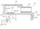
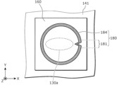
- FIG. 4 is a first cross-sectional view showing the membrane member 160 and its surrounding structure according to the embodiment.
- a cross section of a part of the energy storage device 10 in the XZ plane parallel to the line IV-IV in FIG. 1 is simply illustrated.
- the bus bar holder 300 and the bus bar 400 are omitted, and one of the multiple energy storage elements 200 is illustrated in a schematic manner.
- the arrangement of white arrows in FIG. 4 represents the gas flow path 250 when gas is discharged from the energy storage element 200.
- the gas flow path 250 shown in FIG. 4 does not take into account the presence of the bus bar holder 300.
- the gas flow path 250 is formed from the energy storage element 200 through the path exit 318 of the path forming portion 319 (see FIG. 2) to the outside of the exterior body 100.
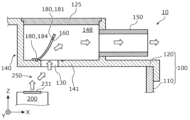
- FIG. 5 is a second cross-sectional view showing the membrane member 160 and its surrounding structure according to the embodiment.
- FIG. 5 shows a simplified cross-section of a portion of the energy storage device 10 in the XY plane parallel to the V-V line in FIG. 1.
- the through-holes 130 hidden by the membrane member 160 are shown by dotted lines. This is also true in a diagram (plan view) of the membrane member 160 as viewed from the positive direction of the Z axis, such as FIG. 7A described below.
- FIG. 6A is a diagram showing the membrane member 160 whose shape has changed as the internal pressure of the exterior body 100 increases.
- FIG. 6B is a diagram showing the membrane member 160 whose part has peeled off from the wall portion 141 as the internal pressure of the exterior body 100 increases.
- the exterior body 100 has a ventilation section 140 having a wall section 141 with a through hole 130.
- the ventilation section 140 forms a ventilation chamber 148 through which gas passes when the gas moves between the inside of the exterior body 100 (the space in the internal space of the exterior body 100 excluding the ventilation section 140, the same applies below) and the outside.
- a membrane member 160 that blocks the through hole 130 is joined to the wall section 141.
- An exhaust pipe 150 is connected to the ventilation section 140.
- a through hole 130 is provided in a wall portion 141 that separates the ventilation chamber 148 from the inside of the exterior body 100.
- the through hole 130 is blocked by a membrane member 160 that is joined to the wall portion 141.
- the membrane member 160 is a breathable waterproof membrane made of a material that is waterproof and breathable (moisture permeable), such as Gore-Tex (registered trademark) or TEMISH (registered trademark).
- Gore-Tex registered trademark
- TEMISH registered trademark
- the membrane member 160 prevents the water from entering the interior of the exterior body 100.
- the membrane member 160 and the wall portion 141 are joined at the joint 180.
- the joint 180 is a portion where the membrane member 160 and the wall portion 141 are joined by welding.
- the joint 180 is formed around the through hole 130. More specifically, the joint 180 is formed in a ring-like and linear shape surrounding the through hole 130.
- the joint 180 is formed by thermal welding, which uses a heated metal body to fuse the film member 160 and the wall portion 141 together.
- the method for forming the joint 180 is not limited to this, and other methods such as laser welding, vibration welding, or ultrasonic welding may be used to form the joint 180.
- the method for joining the film member 160 and the wall portion 141 at the joint 180 is not limited to welding, and the film member 160 and the wall portion 141 may be joined using an adhesive or double-sided tape. In either case, the shape of the joint 180 when viewed from the Z-axis direction can be formed into the shape shown in Figure 5.
- the joint 180 has a first joint 181 and a second joint 184 which is a portion other than the first joint 181.
- the first joint 181 is a portion which is more likely to peel off from the wall 141 than the second joint 184, and is a portion which is provided intentionally.
- the term "easily peeled off” means that when pressure is applied to the membrane member 160, the first joint 181 separates from the wall 141 before the second joint 184 does.
- gas is discharged from the gas discharge valve 231 of the energy storage element 200, the internal pressure of the exterior body 100 rises rapidly, and the membrane member 160 receives pressure in the downstream direction (positive Z-axis direction in FIG. 4) in the gas flow path 250.
- the membrane member 160 expands toward the inside of the ventilation chamber 148 as shown in FIG. 6A, and the resulting stress is applied to the joint 180.
- the membrane member 160 starts peeling from the first joint 181, which is the part most likely to peel off. After that, the bond between the membrane member 160 and the wall portion 141 at the first joint 181 is released, and the stress applied to the second joint 184 increases. As a result, peeling from the wall portion 141 at the second joint 184 progresses. In other words, the intentionally provided first joint 181 becomes the starting point of peeling, which makes peeling at the second joint 184 more likely to occur. If peeling at the second joint 184 progresses to a certain extent, as shown in FIG. 6B, even if a part of the membrane member 160 is joined to the wall portion 141 at the second joint 184, the through hole 130 can be substantially opened (not blocked). As a result, the gas inside the exterior body 100 can be quickly guided to the outside of the exterior body 100 via the ventilation chamber 148 and the exhaust pipe 150.
- a portion of the membrane member 160 remains joined to the wall portion 141, but when gas is discharged from at least one energy storage element 200, the membrane member 160 may be separated from the wall portion 141 due to an increase in the internal pressure of the exterior body 100. In other words, the joining between the membrane member 160 and the wall portion 141 may be released over the entire area of the joint 180.
- an opening is provided at the upper end (the end in the positive direction of the Z axis) of the ventilation section 140, and when assembling the energy storage device 10, the membrane member 160 is joined to the wall section 141 through this opening. After the membrane member 160 is joined to the wall section 141, the opening is closed with the cover member 125. Specifically, the opening and the cover member 125 are joined by a specified method such as adhesive bonding, heat welding, or screw fastening. This maintains a relatively high level of airtightness against gas or liquid between the opening and the cover member 125.
- the ventilation section 140 is disposed in the exterior body 100 as an integral part of the lid 120 of the exterior body 100.
- the ventilation section 140 which is a separate body (separate part) from the exterior body 100, may be attached to the exterior body 100.
- the wall section 141 in which the through hole 130 is formed may be integral with the exterior body 100 or may be separate from the exterior body 100. Even if the wall section 141 is directly or indirectly attached to an exterior body 100 that does not have the wall section 141, the wall section 141 is expressed as "the wall section 141 of the exterior body 100". Regardless of whether the wall section 141 is integral with the exterior body 100 or separate from it, the wall section 141 is disposed somewhere inside the exterior body 100, and is therefore also expressed as "the wall section 141 disposed inside the exterior body 100".
- the exhaust pipe 150 is a separate member from the exterior body 100, but the exhaust pipe 150 may be disposed in the exterior body 100 as an integral member with the exterior body 100. If the ventilation section 140 is separate from the exterior body 100, the exhaust pipe 150 may be disposed in the exterior body 100 as part of the ventilation section 140 (an integral member with the ventilation section 140).
- the energy storage device 10 includes the energy storage element 200, the exterior body 100 that houses the energy storage element 200, and the membrane member 160 that closes the through hole 130 formed in at least one of the wall portion 141 of the exterior body 100 and the wall portion 141 arranged inside the exterior body 100.
- the through hole 130 forms a part of the gas flow path 250.
- the membrane member 160 and the wall portion 141 are joined at a joint portion 180 formed around the through hole 130.
- the joint portion 180 has a first joint portion 181.
- the first joint portion 181 is a portion where the membrane member 160 is more likely to peel off from the wall portion 141 than the second joint portion 184, which is a portion of the joint portion 180 other than the first joint portion 181.
- a portion of the joint 180 which joins the membrane member 160 and the wall portion 141, is intentionally provided with a portion that is easily peeled off (first joint 181). Therefore, when gas is discharged, the first joint 181 becomes the starting point for peeling between the membrane member 160 and the wall portion 141, and peeling of the membrane member 160 from the wall portion 141 also becomes likely to occur at the second joint 184. As a result, the gas blocking by the membrane member 160 is released over a wide area of the through hole 130, and the gas is quickly discharged to the outside.
- the joint 180 in this embodiment has a first joint 181 which is the starting point of peeling, and has a second joint 184 which is less susceptible to peeling than the first joint 181 as a portion other than the first joint 181.
- This maintains the resistance of the joint 180 as a whole to peeling under normal circumstances, while improving the reliability of releasing the gas blocking by the membrane member 160 when gas is discharged.
- problems such as part of the membrane member 180 peeling off from the wall at an unexpected time are less likely to occur.
- the energy storage device 10 in this embodiment is an energy storage device with improved reliability.
- the joint 180 is a part that joins the membrane member 160 and the wall portion 141, and is located at a position on the wall portion 141 outside the through hole 130 when viewed from the penetration direction of the through hole 130.
- the membrane member 160 is joined to the inner surface of the wall portion 141.
- the inner surface of the wall portion 141 is one surface in the thickness direction of the wall portion 141, and in this embodiment, is the surface downstream of the gas flow path 250 when gas is exhausted from the energy storage element 200. Therefore, even if gas or foreign matter that has flowed into the interior of the ventilation chamber 148 via the exhaust pipe 150 collides with the joint portion 180, the joint portion 180 is unlikely to be displaced or deformed because it is supported by the wall portion 141. Therefore, deterioration of the joint portion 180 due to the collision of the gas or foreign matter is unlikely to occur.
- the ease of peeling off of the first joint 181 from the wall portion 141 is achieved by the shape of the first joint 181 when viewed from the Z-axis direction.
- the first joint 181 is a curved portion when viewed from the penetration direction of the through hole 130. That is, the energy storage device 10 according to this embodiment can be described as follows.
- the energy storage device 10 includes an energy storage element 200, an exterior body 100 that houses the energy storage element 200, and a membrane member 160 that closes a through hole 130 formed in at least one of the wall portion 141 of the exterior body 100 and the wall portion 141 arranged inside the exterior body 100.
- the through hole 130 forms a part of the gas flow path 250.
- the membrane member 160 and the wall portion 141 are joined at a joint 180 formed around the through hole 130.
- the joint 180 has a first joint 181.
- the first joint portion 181 is a bent portion when viewed from the penetration direction of the through hole 130.
- the first joint 181 has a curved shape, stress is likely to concentrate at its apex portion 182 (see FIG. 5). In other words, when gas pressure is applied to the membrane member 160, the stress caused by that pressure is concentrated at the curved first joint 181. As a result, the first joint 181 is likely to become the starting point for peeling of the membrane member 160 from the wall portion 141. In this manner, in this embodiment, the first joint 181, which is the starting point for peeling, is formed by the simple method of providing a curved portion in part of the joint 180.
- the membrane member 160 may be welded to the wall portion 141 using a metal body having a circular tip portion that is annular when viewed from the negative Z-axis direction and that has a portion of the circular tip that is bent inward.
- the bent portion of the tip forms the first joint 181 of a bent shape
- the portion of the tip other than the bent portion forms the second joint 184.
- the joint 180 of the shape shown in FIG. 5 may be formed by welding the membrane member 160 to the wall portion 141 using a metal body having a tip portion of approximately the same size and shape as the joint 180 of the shape shown in FIG. 5.
- the membrane member 160 and its surrounding configuration in the energy storage device 10 may be different from the configuration shown in Figures 4 to 6B. Therefore, below, modified examples of the membrane member 160 and its surrounding configuration will be described, focusing on the differences from the above embodiment.
- Fig. 7A is a plan view showing the shape of a bonding portion 180a according to the first modification of the embodiment.
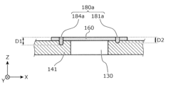
- Fig. 7B is a cross-sectional view showing the difference in size between a first bonding portion 181a and a second bonding portion 184a according to the first modification of the embodiment.
- the position of the cross section in Fig. 7B corresponds to the position of the cross section shown in Fig. 4.
- the joint 180a is a portion that joins the membrane member 160 and the wall portion 141, and is disposed around the through hole 130 when viewed from the Z-axis direction.
- the joint 180a has a first joint 181a and a second joint 184a.
- the first joint 181a is a portion that is more likely to peel off from the wall portion 141 than the second joint 184a.
- the joint 180a in this modified example and the joint 180 in the embodiment are common.
- This modified example differs from the joint 180 in the above embodiment in that the joint strength of the first joint 181a in this modified example is smaller than the joint strength of the second joint 184a.
- the ease with which the first joint 181a peels off from the wall portion 141 is achieved by the relatively small joint strength of the first joint 181a.
- the first bonding portion 181a which serves as the starting point for peeling, can be formed.
- a small bonding strength means that when pressure is applied evenly to the bonding portion 180a, the first bonding portion 181a separates from the wall portion 141 before the second bonding portion 184a does.
- the joint 180a in this modified example is a portion where the membrane member 160 and the wall portion 141 are joined by welding.
- the welding depth D1 of the first joint 181a is smaller than the welding depth D2 of the second joint 184a.
- the welding depths D1 and D2 are the lengths in the penetrating direction of the through hole 130 and also the lengths in the direction in which the membrane member 160 and the wall portion 141 face each other. This creates a state in which the bonding strength of the first joint 181a is smaller than the bonding strength of the second joint 184a.
- the first joint 181a which is the starting point of peeling, is formed by a simple method of adjusting the welding depths of the first joint 181a and the second joint 184a, respectively.
- the bonding portion 180a has the first bonding portion 181a that becomes the starting point of peeling, and has the second bonding portion 184a, which is less likely to peel off than the first bonding portion 181a, as a portion other than the first bonding portion 181a.
- the membrane member 160 may be heat-welded to the wall portion 141 using a metal body having a ring-shaped tip portion when viewed from the negative Z-axis direction, and a recess in the positive Z-axis direction in part of the ring shape.
- the recess that is part of the ring-shaped tip portion forms the first bonding portion 181a with a small welding depth
- the part of the tip portion other than the recess forms the second bonding portion 184a with a large welding depth.
- the method of forming the bonding portion 180a by heat welding is not limited to this.
- a groove may be provided in the part of the wall portion 141 where the first bonding portion 181a is to be formed, and the membrane member 160 may be heat-welded to the wall portion 141 using a metal body having a ring-shaped and flat tip portion (a tip portion without recesses or protrusions in the Z-axis direction). Even in this case, the bonding portion 180a including the first bonding portion 181a with a welding depth smaller than that of the second bonding portion 184a is formed.
- Fig. 8A is a plan view showing the shape of a bonding portion 180b according to the second modification of the embodiment.
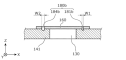
- Fig. 8B is a cross-sectional view showing the difference in size between a first bonding portion 181b and a second bonding portion 184b according to the second modification of the embodiment.
- the position of the cross section in Fig. 8B corresponds to the position of the cross section shown in Fig. 4.
- the joint 180b is a portion that joins the membrane member 160 and the wall portion 141, and is arranged around the through hole 130 when viewed from the Z-axis direction.
- the joint 180b has a first joint 181b and a second joint 184b.
- the first joint 181b is a portion that is more likely to peel off from the wall portion 141 than the second joint 184b.
- the joint 180b in this modified example is a portion where the membrane member 160 and the wall portion 141 are joined by welding, and the joining strength of the first joint 181b is smaller than the joining strength of the second joint 184b. In these configurations, the joint 180b in this modified example and the joint 180a in the modified example 1 are common.
- the welding width W1 of the first joint 181b is smaller than the welding width W2 of the second joint 184b.
- the widths W1 and W2 of the welded portion are the lengths in the direction perpendicular to the penetration direction of the through hole 130 and the extension direction of the joint 180, and are also the lengths in the direction in which the membrane member 160 and the wall portion 141 face each other and in the direction perpendicular to the extension direction of the joint 180.
- the first joint 181b which is the starting point of peeling, is formed by the simple method of adjusting the width of the welding at each of the first joint 181b and the second joint 184b.
- the bonding portion 180b has the first bonding portion 181b that becomes the starting point of peeling, and has the second bonding portion 184b, which is less likely to peel off than the first bonding portion 181b, as a portion other than the first bonding portion 181b.
- the state in which the bonding strength of the first bonding portion 181b is smaller than the bonding strength of the second bonding portion 184b can be achieved even when the bonding portion 180b is formed using an adhesive or double-sided tape.
- the width of the adhesive or double-sided tape at the first bonding portion 181b is made smaller than the width of the adhesive or double-sided tape at the second bonding portion 184b. This also makes it possible to make the bonding strength at the first bonding portion 181b smaller than the bonding strength at the second bonding portion 184b.
- the membrane member 160 may be heat welded to the wall portion 141 using a metal body having a ring-shaped tip portion when viewed from the negative Z-axis direction, with a thin-walled portion in part of the ring shape that has a smaller radial thickness than the other portions.
- the thin-walled portion that is part of the ring-shaped tip portion forms a first joint 181b with a narrow weld width
- the portion of the tip other than the thin-walled portion forms a second joint 184b with a wide weld width.
- the joint 180b in this modification may further have the characteristics of the joint 180a in modification 1.
- the first joint 181b may have a smaller welding width and depth than the second joint 184b.
- both the welding width and depth of the first joint 181b may be adjusted to adjust the susceptibility of peeling at the first joint 181b.
- FIG. 9 is a plan view showing the shape of a joint 180c according to the third modified example of the embodiment.
- the joint 180c shown in FIG. 9 is a part that joins the membrane member 160 and the wall portion 141, and is arranged around the through hole 130 when viewed from the Z-axis direction.
- the joint 180c has a first joint 181c and a second joint 184c.
- the first joint 181c is a part that is more likely to peel off from the wall portion 141 than the second joint 184c.
- the first joint 181c according to this modified example is a part that has a bent shape when viewed from the Z-axis direction.
- the joint 180c according to this modified example and the joint 180 according to the embodiment are common.
- both ends of two joints that are formed in a curved line shape cross each other, forming a bent-shaped part (first joint 181c) with the intersection point as an apex.
- the first bonding portion 181c has a bent shape, and therefore stress tends to concentrate at its apex.
- the first bonding portion 181c tends to be the starting point for peeling (delamination) of the membrane member 160 from the wall portion 141.
- peeling also tends to occur at the second bonding portion 184c, and the gas inside the exterior body 100 is quickly discharged to the outside.
- the bonding portion 180c as a whole is normally unlikely to peel, while improving the reliability of releasing the gas blocking by the membrane member 160 when gas is discharged from the energy storage element 200.
- the joint 180c may be formed by adhesive or double-sided tape instead of welding, just like the joint 180 in the above embodiment.
- Fig. 10 is a plan view showing the positional relationship between the through hole 130a and the joint portion 180 according to the fourth modified example of the embodiment.
- the joint portion 180 shown in Fig. 10 is the same as the joint portion 180 according to the above embodiment (see Fig. 5), and has a second joint portion 184 and a first joint portion 181 which is a portion where the membrane member 160 is more likely to peel off from the wall portion 141 than the second joint portion 184.
- the shape of the through hole 130a when viewed from the penetration direction (Z-axis direction) is elongated in the X-axis direction, which differs from the through hole 130 in the above embodiment.
- the through hole 130a has a non-circular shape that is elongated in one direction (the X-axis direction in this modified example) when viewed from the Z-axis direction.
- the first joint 181 is located in the X-axis direction of the through hole 130a (the positive X-axis direction in this modified example).
- This configuration allows the distance between the periphery of the through hole 130a and the first joint 181 to be relatively short. This allows the pressure of the gas attempting to escape to the outside from the through hole 130a to act efficiently on the first joint 181. As a result, peeling of the membrane member 160 from the wall portion 141 starting from the first joint 181 is likely to occur. This is advantageous for rapid gas discharge from the inside of the exterior body 100 to the outside.
- the joint 180 may be replaced with the joints 180a to 180c (see Figures 7A, 8A, and 9) according to the above modifications 1 to 3.
- the pressure of the gas attempting to escape to the outside from the through hole 130a can be efficiently applied to one of 181a to 181c.
- FIG. 11A is a plan view showing the positional relationship between the through hole 130b and the joint portion 180 according to the fifth modified example of the embodiment.
- FIG. 11B is a cross-sectional view showing the positional relationship between the tapered portion 132a and the first joint portion 181 according to the fifth modified example of the embodiment.
- the position of the cross section in FIG. 11B corresponds to the position of the cross section shown in FIG. 4.
- FIG. 11C is a plan view showing a through hole 130c having an outlet (a downstream opening of the gas flow path 250) with a different shape from the through hole 130b shown in FIG. 11A.
- the through hole 130c shown in FIG. 11C is an example of a through hole having a tapered portion 132a (see FIG. 11B) like the through hole 130b shown in FIG. 11A, and having an outlet with a different shape from the through hole 130b (see FIG. 11A).
- the joint 180 shown in Figures 11A to 11C is the same as the joint 180 in the above embodiment (see Figure 5), and has a second joint 184 and a first joint 181, which is a portion where the membrane member 160 is more likely to peel off from the wall portion 141 than the second joint 184.
- the inner surface 132 of the through hole 130b has a portion that is inclined in a direction approaching the first joint portion 181, which differs from the through hole 130 in the above embodiment. That is, in this modified example, the wall portion 141 has a tapered portion 132a on the inner surface 132 of the through hole 130b that is inclined in a direction approaching the first joint portion 181 as it approaches the membrane member 160.
- the inner surface 132 of the through hole 130b is the inner circumferential surface of the through hole 130b, and is the portion that faces the gas when the gas passes through the through hole 130b.
- the cross-sectional area of through hole 130b narrows as it approaches the exit of through hole 130b, and the gas flows in a direction approaching first joint 181. This allows the pressure of the gas passing through through hole 130b and flowing toward the outside of exterior body 100 to act efficiently on first joint 181. As a result, peeling of membrane member 160 from wall portion 141 starting from first joint 181 is likely to occur. This is advantageous for rapid gas discharge from the inside of exterior body 100 to the outside.
- the shape of the outlet of the through hole 130b is not limited to the shape shown in FIG. 11A, and various shapes may be adopted.
- the tapered portion 132a may be provided on the inner surface 132 of 130c having an outlet shaped in which a part (arc) of a circle is replaced with a straight line. Even in this case, the tapered portion 132a is inclined in the direction approaching the first joint portion 181 as it approaches the membrane member 160, so that the pressure of the gas passing through the through hole 130c and heading toward the outside of the exterior body 100 acts efficiently on the first joint portion 181. As a result, peeling of the membrane member 160 from the wall portion 141 starting from the first joint portion 181 is likely to occur.
- the energy storage device 10 may not have a path forming portion 319 provided on the bus bar holder 300.
- the bus bar holder 300 may have one or more through holes that allow gas to pass through in the Z-axis direction in a range that includes the area facing each gas exhaust valve 231 of the multiple energy storage elements 200. In other words, gas exhausted from at least one of the multiple energy storage elements 200 may move inside the exterior body 100 without being restricted by the path forming portion 319.
- the energy storage device 10 does not need to include a bus bar holder 300. If it is easy to position the multiple bus bars 400, or if each of the multiple energy storage elements 200 is protected by an insulating member such as a cell holder, each of the multiple bus bars 400 can be positioned in a predetermined position without including a bus bar holder 300.
- the wall portion 141 in which the through hole 130 is provided does not need to be arranged in a position with its thickness direction facing the Z-axis direction as shown in FIG. 4. There are no particular limitations on the position and position of the wall portion 141 as long as it is in a position where it receives pressure inside the exterior body 100.
- the wall portion 141 may have a cylindrical portion that protrudes in at least one direction in the thickness direction (the Z-axis direction in this embodiment) and extends the length of the through hole 130 (the length in the penetration direction).
- the through hole 130 of the wall portion 141 may be formed by a cylindrical portion provided in the wall portion 141.
- the cylindrical portion may be provided integrally with the wall portion 141, or a separate cylindrical portion (separate part) may be attached to the wall portion 141.
- the exhaust pipe 150 does not have to be arranged in the exterior body 100. Gas that has passed through the through hole 130 may be exhausted from an opening provided on the outer surface of the exterior body 100.
- the exterior body 100 may not have the ventilation section 140 and the ventilation chamber 148.
- a through hole 130 may be provided in a wall section of the lid body 120 or the exterior body main body 110 of the exterior body 100 that separates the inside and outside of the exterior body 100.
- the membrane member 160 may be joined at a position that blocks the through hole 130 on the outer surface of the wall section.
- the membrane member 160 and the joint section 180 may be positioned at a position that is visible from the outside of the exterior body 100.
- the membrane member 160 does not have to be a breathable waterproof membrane. From the viewpoint of suppressing the intrusion of water into the interior of the exterior body 100, the membrane member 160 may be formed of a material that has a waterproof function but does not have a breathable function. There are no particular limitations on the size and shape of the membrane member 160 in a planar view and the size and shape of the outlet of the through hole 130 in a planar view. These sizes and shapes may be any size and shape that allows the membrane member 160 to block the through hole 130. In either case, the membrane member 160 blocks the through hole 130 and is joined to the wall portion having the through hole 130 at the joint 180, thereby achieving the above-mentioned effect of being able to quickly exhaust gas inside the exterior body 100 to the outside.
- the first bonding portion 181 is bent, and the bonding strength of the first bonding portion 181a is smaller than the bonding strength of the second bonding portion 184a.
- the first bonding portion 181 is positioned in one direction of the through hole 130a, and a tapered portion 132a is provided on the inner surface of the wall portion 141.
- any method may be used as long as the first bonding portion is more easily peeled off from the wall portion than the second bonding portion.
- the surface of the wall portion may be chemically or physically treated to inhibit the formation of the first bonding portion, or a gap may be provided in part of the first bonding portion. These two methods may be combined.
- the present invention can be applied to energy storage devices equipped with energy storage elements such as lithium-ion secondary batteries.
- Electricity storage device 100 Exterior body 130, 130a, 130b, 130c Through hole 132 Inner surface 132a Tapered portion 140 Vent portion 141 Wall portion 148 Vent chamber 150 Exhaust pipe 160 Membrane member 180, 180a, 180b, 180c Joint portion 181, 181a, 181b, 181c First joint portion 182 Vertex portion 184, 184a, 184b, 184c Second joint portion 200 Electricity storage element 250 Gas flow path
Landscapes
- Engineering & Computer Science (AREA)
- Power Engineering (AREA)
- Chemical & Material Sciences (AREA)
- Chemical Kinetics & Catalysis (AREA)
- Electrochemistry (AREA)
- General Chemical & Material Sciences (AREA)
- Microelectronics & Electronic Packaging (AREA)
- Sealing Battery Cases Or Jackets (AREA)
Priority Applications (1)
| Application Number | Priority Date | Filing Date | Title |
|---|---|---|---|
| JP2024549383A JPWO2024071059A1 (https=) | 2022-09-28 | 2023-09-26 |
Applications Claiming Priority (2)
| Application Number | Priority Date | Filing Date | Title |
|---|---|---|---|
| JP2022155335 | 2022-09-28 | ||
| JP2022-155335 | 2022-09-28 |
Publications (1)
| Publication Number | Publication Date |
|---|---|
| WO2024071059A1 true WO2024071059A1 (ja) | 2024-04-04 |
Family
ID=90477873
Family Applications (1)
| Application Number | Title | Priority Date | Filing Date |
|---|---|---|---|
| PCT/JP2023/034797 Ceased WO2024071059A1 (ja) | 2022-09-28 | 2023-09-26 | 蓄電装置 |
Country Status (2)
| Country | Link |
|---|---|
| JP (1) | JPWO2024071059A1 (https=) |
| WO (1) | WO2024071059A1 (https=) |
Citations (3)
| Publication number | Priority date | Publication date | Assignee | Title |
|---|---|---|---|---|
| JP2002324536A (ja) * | 2001-04-26 | 2002-11-08 | Yuasa Corp | 密閉形電池 |
| JP2017152162A (ja) * | 2016-02-23 | 2017-08-31 | 株式会社Gsユアサ | 蓄電装置 |
| WO2021049315A1 (ja) * | 2019-09-10 | 2021-03-18 | ビークルエナジージャパン株式会社 | 電池パック |
-
2023
- 2023-09-26 JP JP2024549383A patent/JPWO2024071059A1/ja active Pending
- 2023-09-26 WO PCT/JP2023/034797 patent/WO2024071059A1/ja not_active Ceased
Patent Citations (3)
| Publication number | Priority date | Publication date | Assignee | Title |
|---|---|---|---|---|
| JP2002324536A (ja) * | 2001-04-26 | 2002-11-08 | Yuasa Corp | 密閉形電池 |
| JP2017152162A (ja) * | 2016-02-23 | 2017-08-31 | 株式会社Gsユアサ | 蓄電装置 |
| WO2021049315A1 (ja) * | 2019-09-10 | 2021-03-18 | ビークルエナジージャパン株式会社 | 電池パック |
Also Published As
| Publication number | Publication date |
|---|---|
| JPWO2024071059A1 (https=) | 2024-04-04 |
Similar Documents
| Publication | Publication Date | Title |
|---|---|---|
| JP2006040901A (ja) | 二次電池 | |
| KR20190106073A (ko) | 이차전지 | |
| US20250246748A1 (en) | Energy storage device and energy storage apparatus | |
| JP2024021479A (ja) | 蓄電装置 | |
| JP7669652B2 (ja) | 蓄電素子 | |
| JP7721939B2 (ja) | 蓄電装置 | |
| JP7631718B2 (ja) | 蓄電素子 | |
| WO2024071059A1 (ja) | 蓄電装置 | |
| JP7434211B2 (ja) | 電池 | |
| WO2023048040A1 (ja) | 蓄電装置 | |
| US11355826B2 (en) | Secondary battery | |
| JP7739726B2 (ja) | 蓄電素子 | |
| JP7718040B2 (ja) | 蓄電素子 | |
| JP7706431B2 (ja) | 電池 | |
| JP2025007972A (ja) | 蓄電装置 | |
| WO2026079349A1 (ja) | 蓄電装置 | |
| JP2025128615A (ja) | 蓄電素子 | |
| WO2026088605A1 (ja) | 蓄電素子 | |
| JP2025177223A (ja) | 蓄電素子 | |
| WO2025187419A1 (ja) | 蓄電素子 | |
| WO2024150803A1 (ja) | 蓄電素子及びその製造方法 | |
| JP2024065619A (ja) | 蓄電素子及び蓄電素子の製造方法 | |
| JP2024100044A (ja) | 蓄電素子 | |
| JP2024066623A (ja) | 蓄電装置、及び、蓄電装置の製造方法 | |
| JP2026059050A (ja) | 蓄電装置およびその製造方法 |
Legal Events
| Date | Code | Title | Description |
|---|---|---|---|
| 121 | Ep: the epo has been informed by wipo that ep was designated in this application |
Ref document number: 23872282 Country of ref document: EP Kind code of ref document: A1 |
|
| WWE | Wipo information: entry into national phase |
Ref document number: 2024549383 Country of ref document: JP |
|
| NENP | Non-entry into the national phase |
Ref country code: DE |
|
| 122 | Ep: pct application non-entry in european phase |
Ref document number: 23872282 Country of ref document: EP Kind code of ref document: A1 |