WO2024070970A1 - 吊下げ器具 - Google Patents
吊下げ器具 Download PDFInfo
- Publication number
- WO2024070970A1 WO2024070970A1 PCT/JP2023/034569 JP2023034569W WO2024070970A1 WO 2024070970 A1 WO2024070970 A1 WO 2024070970A1 JP 2023034569 W JP2023034569 W JP 2023034569W WO 2024070970 A1 WO2024070970 A1 WO 2024070970A1
- Authority
- WO
- WIPO (PCT)
- Prior art keywords
- fold line
- container
- hanging
- support
- valley
- Prior art date
- Legal status (The legal status is an assumption and is not a legal conclusion. Google has not performed a legal analysis and makes no representation as to the accuracy of the status listed.)
- Ceased
Links
Images














Classifications
-
- A—HUMAN NECESSITIES
- A61—MEDICAL OR VETERINARY SCIENCE; HYGIENE
- A61J—CONTAINERS SPECIALLY ADAPTED FOR MEDICAL OR PHARMACEUTICAL PURPOSES; DEVICES OR METHODS SPECIALLY ADAPTED FOR BRINGING PHARMACEUTICAL PRODUCTS INTO PARTICULAR PHYSICAL OR ADMINISTERING FORMS; DEVICES FOR ADMINISTERING FOOD OR MEDICINES ORALLY; BABY COMFORTERS; DEVICES FOR RECEIVING SPITTLE
- A61J1/00—Containers specially adapted for medical or pharmaceutical purposes
- A61J1/14—Details; Accessories therefor
- A61J1/16—Holders for containers
-
- A—HUMAN NECESSITIES
- A61—MEDICAL OR VETERINARY SCIENCE; HYGIENE
- A61M—DEVICES FOR INTRODUCING MEDIA INTO, OR ONTO, THE BODY; DEVICES FOR TRANSDUCING BODY MEDIA OR FOR TAKING MEDIA FROM THE BODY; DEVICES FOR PRODUCING OR ENDING SLEEP OR STUPOR
- A61M5/00—Devices for bringing media into the body in a subcutaneous, intra-vascular or intramuscular way; Accessories therefor, e.g. filling or cleaning devices, arm-rests
- A61M5/14—Infusion devices, e.g. infusing by gravity; Blood infusion; Accessories therefor
Definitions
- the present invention relates to a hanging device for suspending a container that stores a liquid to be administered to a patient via a medical tube.
- Non-Patent Document 1 a spout provided at one longitudinal end of a roughly rectangular parallelepiped container is connected to a connector of a medical tube, while a hanging device is attached to the other longitudinal end of the container and the hanging device is attached to a garter stand to hang the container from the garter stand.
- the hanging device has a resin device body that is open on one side and has a circular tray shape with an outer peripheral wall that extends in a ring shape around a center line, and a tongue portion having a hanging hole is erected at the center of the other side surface of the device body.
- each engagement claw is positioned with a slit-shaped gap from the bottom surface of the device body.
- the dimension between two adjacent engagement claws corresponds to the dimension of one side of the other longitudinal end surface of the container.
- Non-Patent Document 1 has a complex three-dimensional shape that is integrally molded from resin, including multiple engaging claws and tongues, so it is bulky when stored and difficult to handle.
- the present invention was made in consideration of these points, and its purpose is to provide a hanging device that is easy to handle.
- the present invention is characterized in that the device body is in the form of a sheet before use, or in the form of a folded double sheet before use, and is deformed when in use.
- the following solution was implemented for a hanging device that has an outlet to which a medical tube can be connected and that suspends a container that stores a liquid to be administered to a patient via the medical tube.
- the first invention is characterized in that it comprises an instrument body that is in the form of a flat sheet with both sides before use, or in the form of a double sheet that is folded before use, and that the instrument body has a deformation part that is formed by bending the front or back side of the instrument body when in use, or is formed by spreading out the folded part of the instrument body when in use, and a base part that is composed of the area excluding the deformation part, and that the deformation part is provided with a holding part that holds the container between the base part and the deformation part, and a support part that supports the container from below.
- the second invention is the first invention, characterized in that the device body is made of paper.
- the third invention is characterized in that in the first invention, the support portion is configured to support the periphery of the spout portion from below.
- the fourth invention is characterized in that, in the first or third invention, the device main body has a hanging part provided at one end side portion or the other end side portion, and an opening portion that can correspond to the spout portion is provided at the middle portion, the holding part, the support part, and the base part are respectively configured as one end side region, middle portion region, and other end side region of the device main body, and the device main body is configured such that the holding part and the support part are curved and deformed with the opening corresponding to the spout portion, and the one end portion and the other end portion are connected to form a ring to surround the container, so that the holding part and the base part hold the main body portion of the container, and the support part supports the container from below to bring it into a usable state.
- the fifth invention is the fourth invention, characterized in that the suspended part is provided at one end of the tool body and has a narrower shape than other areas of the tool body, and the other end of the tool body is formed with an engaged hole into which the suspended part can be inserted, and the suspended part is inserted into the engaged hole and its base is abutted against the opening periphery of the engaged hole, thereby engaging and connecting the one end and the other end of the tool body.
- the device body is formed with a pair of slits extending side by side, the spacing between the portion extending from one end to the middle portion corresponding to the width dimension of the spout portion, while the spacing between the other end side corresponding to the width dimension of the main body portion of the container, and a hanging portion is provided at the other end portion
- the holding portion is formed at the middle portion of the area outside the slits in the device body
- the support portion is formed by a first support area located at one end side of the area outside the slits in the device body and a second support area located at one end side between the two slits
- the base portion is formed in the other end region between the two slits in the device body, and the device body is configured to bend and deform the holding portion and the first support region so that they jut out toward the front side, and to bend and deform the second support region so that they jut out toward the back side, so that the container is inserted between the holding portion and
- the seventh invention is characterized in that, in the first or third invention, the holding portion is formed between a pair of first slits formed to extend side by side in the device body, the support portion is formed between a pair of second slits formed to extend side by side in the same direction as the first slits on one side of the device body in the direction of juxtaposition of the first slits, and a suspended portion is provided on the other side of the device body in the direction of juxtaposition of the first slits, and the device body is configured to hold the main body of the container between the holding portion and the base portion by bending and deforming the holding portion and the support portion so that they jut out toward the front side and the base portion so that they jut out toward the back side, and to insert the container between the holding portion and the base portion that are spaced apart from each other so that the spout portion is on the support portion side, and to support the container from below with the support portion to bring it into use.
- the container has a hexahedral shape with four consecutive side surfaces in the circumferential direction of the main body portion having the same width dimension, and a first mountain fold line extending in the parallel arrangement direction of the two first slits is provided in the center of the holding portion surface side, while a first valley fold line extending in the same direction as the first mountain fold line is provided in each continuous portion with the base portion on the holding portion surface side, and the dimension between the first mountain fold line and each of the first valley fold lines corresponds to the width dimension of the side of the container, and a second mountain fold line extending in the same direction as the first mountain fold line is provided in a position corresponding to the first mountain fold line on the support portion surface side, while a second mountain fold line extending in the same direction as the first mountain fold line is provided in each continuous portion with the base portion on the support portion surface side.
- a second valley fold line extending in the same direction as the second mountain fold line is provided at each continuous portion with the base portion, and a third valley fold line extending in the same direction as the first mountain fold line is provided at a position on the surface side of the base portion corresponding to the first mountain fold line, and the device body is characterized in that the holding portion is bent and deformed so as to protrude toward the surface side by mountain folding at the first mountain fold line and valley folding at each of the first valley fold lines, the support portion is bent and deformed so as to protrude toward the surface side by mountain folding at the second mountain fold line and valley folding at each of the second valley fold lines, and the base portion is bent and deformed so as to protrude toward the back side by valley folding at the third valley fold line to be in a usable state.
- the ninth invention is the seventh invention, characterized in that the support parts are provided in pairs at a predetermined interval in the extension direction of the second slit, and each support both sides in the width direction of the surrounding portion of the spout part of the container.
- the container has a hexahedral shape with four consecutive side surfaces in the circumferential direction of the main body portion having the same width dimension, and a pair of first mountain fold lines extending in the parallel arrangement direction of the two first slits are provided on the surface side of the holding portion, while each continuous portion with the base portion on the surface side of the holding portion is provided with a first valley fold line extending in the same direction as each of the first mountain fold lines, and the dimension between the two first mountain fold lines corresponds to the width dimension of the side of the container, and each of the support portions is provided at a position corresponding to each of the first mountain fold lines, and a second mountain fold line extending in the same direction as the first mountain fold line is provided at a position corresponding to the first mountain fold line on each surface side, while A second valley fold line extending in the same direction as the second mountain fold line is provided at each continuous portion with the base portion, and a third valley fold line extending in the same direction as the first mountain fold line is
- the container has a hexahedral shape with four consecutive side surfaces in the circumferential direction of the main body portion having the same width dimension
- the device main body has a hanging portion provided at at least one of the one end side portion and the other end side portion, and an opening corresponding to the spout portion is provided at the middle portion
- the holding portion, the support portion and the base portion are respectively composed of the one end side region, the middle portion region and the other end side region of the device main body
- a support hole is provided in at least one of the holding portion and the base portion
- the continuous portion between the holding portion and the support portion on the surface side of the device main body has , a fourth valley fold line is provided, and a fifth valley fold line is provided at the continuous portion between the support portion and the base portion on the surface side of the device body, and the device body is folded at the fourth valley fold line and the fifth valley fold line to connect one end portion and the other end portion to form a ring so as to surround the container with the
- the holding portion is formed between a pair of third slits formed to extend side by side in the instrument body
- the support portion is formed by the end portion on the other side in the juxtaposition direction of the two third slits in the holding portion
- a hanging portion is provided on the other side in the juxtaposition direction of the two third slits in the instrument body
- a pair of third mountain fold lines extending in the juxtaposition direction of the two third slits are provided on the surface side of the holding portion
- each continuous portion with the base portion on the surface side of the holding portion has a front
- a sixth valley fold line is provided extending in the same direction as each of the third mountain fold lines
- a seventh valley fold line is provided at a position on the surface side of the base portion corresponding to each of the third mountain fold lines, extending in the same direction as each of the third mountain fold lines.
- the device body is characterized in that the holding portion is mountain-folded at each of the third mountain fold lines and valley-folded at each of the sixth valley fold lines to fold and deform so as to protrude toward the surface side, and the base portion is valley-folded at each of the seventh valley fold lines to fold and deform so as to protrude toward the back side, to be in a usable state.
- the thirteenth invention is characterized in that in the first or third invention, the device body is configured to be box-shaped so that a space capable of accommodating the container is formed inside the device body by unfolding the folded portion of the device body.
- the 14th invention is the 13th invention, wherein the device body has a front portion, a back portion, a left side portion, a right side portion, a bottom portion, and an opening provided in at least the bottom portion, the base portion is the front portion and the back portion, the holding portion is the left side portion and the right side portion, and the support portion is the bottom portion, and the device body is capable of supporting the container from the side by the front portion, the back portion, the left side portion, and the right side portion when in use, and is capable of supporting the container from below by the bottom portion when the spout portion of the container is inserted into the opening.
- a first fold line is provided in the connecting portion between the back portion and the bottom portion
- a second fold line is provided in the connecting portion between the front portion and the bottom portion
- a third fold line extending in the same direction as the first fold line is provided between the first fold line and the second fold line in the bottom portion
- a fourth fold line is provided in the connecting portion between the front portion and the left side portion
- a fifth fold line is provided in the connecting portion between the back portion and the left side portion
- a sixth fold line extending in the same direction as the fourth fold line is provided between the fourth fold line and the fifth fold line in the left side portion
- a seventh fold line is provided in the connecting portion between the front portion and the right side portion.
- the device has a folding line, an eighth folding line is provided at the connecting portion between the back portion and the right side portion, and a ninth folding line is provided between the seventh folding line and the eighth folding line on the right side portion, extending in the same direction as the seventh folding line, and the device body in the pre-use state is folded by being folded at the third folding line, the sixth folding line, and the ninth folding line, and the device body during use is folded at the first folding line, the second folding line, the fourth folding line, the fifth folding line, the seventh folding line, and the eighth folding line, so that the folded portion of the device body is expanded to form a box shape.
- the sixteenth invention is the fifteenth invention, characterized in that the opening is provided continuously from the bottom surface portion to the front surface portion, and the second fold lines are provided on both sides of the opening.
- the seventeenth invention is the sixteenth invention, characterized in that the front portion is provided with a window portion, and the window portion is provided at a distance from the opening portion.
- the eighteenth invention is the first invention, characterized in that the device body is provided with a hanging hole that penetrates in the thickness direction.
- the 19th invention is characterized in that in the first invention, a continuous portion between the deformation portion and the base portion, and the deformation portion, are provided with a bending line that serves as a starting point for bending the deformation portion.
- the 20th invention is the 18th invention, characterized in that the device body has two hanging holes.
- the shape of the device before use is a sheet or a folded double sheet, so that it does not take up much space when stored, while when in use, it is only necessary to bend a specific position on the device body to create a place for holding and supporting the container, or to unfold the folded device body, making it an easy-to-handle hanging device.
- the entire device is made of paper, which can greatly contribute to reducing the environmental impact.
- the position of the outlet of the suspended container is stabilized, so that the transport state of the liquid in the container to the medical tube during administration can be stabilized.
- the device when a user uses the hanging device, the device can be used simply by bending and deforming the device body and connecting the ends. In this way, the preparation work of deforming the device body when in use is simplified, making the hanging device easy to use. Furthermore, by changing the size of the annular part of the device body when bending and deforming the device body when in use, the dimension between the holding part and the base part and the length dimension of the support part can be changed, making it possible to change the size of the container to be hung. Therefore, it can be used to hang multiple types of containers, making it a highly versatile hanging device. Furthermore, since the spout part is visible from the opening when hanging a container, the user can easily connect a medical tube to the spout part, making it a hanging device that is easy to use.
- one end of the device body can be connected to the other end simply by inserting the hanging part into the engaging hole, making the preparation work for transforming the device body when in use even easier and allowing the container to be hung efficiently in a short amount of time.
- no adhesives or the like are used when transforming the device body, so processing costs can be kept low.
- the amount of deformation of each region of the device body can be changed to change the dimension between the holding part and the base part and the length dimension of the support part, so that the size of the container to be hung can be changed. Therefore, it can be used to hang multiple types of containers, making it a highly versatile hanging device.
- the outlet part faces from the separated part of the support part, so that the user can easily connect the medical tube to the outlet part, making it a hanging device with good usability.
- the holding part holds the positions on both sides of the width direction of the container at a distance, the content indication etc.
- the support part when the container is attached to the hanging device, the support part supports the container from below with the holding part and base part surrounding the entire side of the container. This makes it possible to prevent the container from accidentally coming off the hanging device, and to prevent the container from falling off the hanging device.
- the area enclosed by the holding part and the base part is roughly square in shape, corresponding to the cross section of the main body of the container, so that the container does not shift relative to the device body when held by the holding part and the base part. This makes it possible to stabilize the attachment state of the container to the hanging device, and reliably prevent the container from falling off the hanging device.
- the support portion supports the container from below at two separate positions on both sides of the container's width, so that when the container is attached to the hanging device, the container's position relative to the device body can be stabilized.
- the surface of the four sides of the container can be attached so that it faces the same direction as the surface of the device body. Therefore, if the surface including the spout is tilted toward the surface of the container, when the hanging device with the container attached is hung, the device body will tilt diagonally toward its back side so that the container moves directly below the hanging position, but as a result, the surface including the spout will extend approximately horizontally. This reduces the amount of liquid remaining in the container at the end of administration, allowing the liquid in the container to be used without waste.
- the main body of the container when the hanging device is in use, the main body of the container is inserted into a support hole provided in at least one of the holding part and the base part. This makes it possible to prevent the container from falling off the hanging device.
- the third slit makes it possible to provide a holding portion and a support portion. This eliminates the need to provide a separate slit for the support portion, for example, and allows the processing costs of the hanging device to be kept low.
- the device body when the folded portion of the device body is unfolded during use, the device body becomes box-shaped, forming a space inside the device body capable of housing a container.
- This box-shaped device body makes it possible to stably support the container housed within the space. Therefore, when the container is suspended, it is possible to prevent the container from falling off the device body.
- the fourteenth invention when the device body is in use and a container is placed within the space of the device body, the container is supported by the rear, front, left side, right side and bottom. Therefore, the device body can stably support the container, and it is possible to prevent the container from falling off the device body when hanging it.
- the spout portion is visible from the opening when hanging the container, the user can easily connect a medical tube to the spout portion, making it possible to create a hanging device that is comfortable to use.
- the first folding line, the second folding line, the third folding line, the fourth folding line, the fifth folding line, the sixth folding line, the seventh folding line, the eighth folding line, and the ninth folding line are used to fold the device body, and to unfold the device body from the folded state for use.
- the opening is provided continuously from the bottom surface to the front surface, so that the second fold line provided at the continuous portion between the bottom surface and the front surface can be made short. This makes it easier to fold the device body at the second fold line.
- the opening can be made wide, the spout portion of the container can be attached to the hanging device without touching the device body, which is hygienic.
- a gap is provided between the opening and the window, that is, a part that connects the left and right parts of the front surface is provided between the opening and the window. This allows the force applied to the main body of the device when in use to be transmitted to the bottom surface via the connecting part, making it easier to unfold the folded main body of the device.
- the container can be hung by hooking the hanging hole onto a hanging body such as a garter stand placed in a medical facility.
- a hanging body such as a garter stand placed in a medical facility.
- the structure for hanging on the hanging body can be easily formed, processing costs can be kept low.
- the continuous portion between the deformation portion and the base portion, and the bending position in the deformation portion are clearly defined and easy to bend. Therefore, medical personnel can change the suspension device from a pre-use state to a usable state efficiently without spending a lot of time.
- the two hanging holes provided in the hanging device are hooked onto the hanging body. This prevents the hanging device from coming off the hanging body due to sudden application of force to the hanging device, causing the container to fall together with the hanging device.
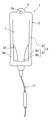
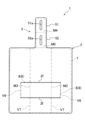
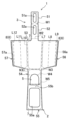
- FIG. 1 is a front view of a suspension device according to a first embodiment of the present invention in a pre-use state.
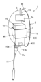
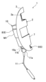
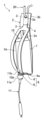
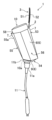
- FIG. 1 is a perspective view of a suspension tool according to a first embodiment of the present invention in use.
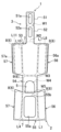
- FIG. 1 is a front view of a suspension device according to a first embodiment of the present invention in a used state.
- FIG. 1 is a side view of a suspension device according to a first embodiment of the present invention in use.
- FIG. 2 is a rear view of the suspension device according to the first embodiment of the present invention in use.
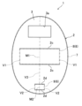
- FIG. 10 is a view corresponding to FIG. 1 according to a second embodiment of the present invention.
- FIG. 4 is a view corresponding to FIG. 2 according to a second embodiment of the present invention.
- FIG. 1 is a front view of a suspension device according to a first embodiment of the present invention in a pre-use state.
- FIG. 1 is a perspective view of a suspension tool according to a first embodiment of the present invention
- FIG. 5 is a view corresponding to FIG. 3 according to a second embodiment of the present invention.
- FIG. 5 is a view corresponding to FIG. 4 according to a second embodiment of the present invention.
- FIG. 6 is a view corresponding to FIG. 5 according to a second embodiment of the present invention.
- FIG. 10 is a view corresponding to FIG. 1 according to a third embodiment of the present invention.
- FIG. 11 is a view corresponding to FIG. 2 according to a third embodiment of the present invention.
- FIG. 5 is a view corresponding to FIG. 3 according to a third embodiment of the present invention.
- FIG. 5 is a view corresponding to FIG. 4 according to a third embodiment of the present invention.
- FIG. 7 is a view corresponding to FIG. 5 according to a third embodiment of the present invention.
- FIG. 13 is a view corresponding to FIG. 12 according to a fourth embodiment of the present invention.
- FIG. 13 is a view according to a fourth embodiment of the present invention.
- FIG. 14 according to a fourth embodiment of the present invention.
- FIG. 15 is a view according to a fourth embodiment of the present invention.
- FIG. 10 is a view corresponding to FIG. 1 according to a fifth embodiment of the present invention.
- FIG. 11 is a view corresponding to FIG. 2 according to a fifth embodiment of the present invention.
- FIG. 11 is a view corresponding to FIG. 1 according to a sixth embodiment of the present invention.
- FIG. 11 is a view corresponding to FIG. 2 according to a sixth embodiment of the present invention.
- FIG. 11 is a view corresponding to FIG. 2 according to a sixth embodiment of the present invention.
- FIG. 11 is a view corresponding to FIG. 4 according to a sixth embodiment of the present invention.
- FIG. 13 is an exploded view of a hanging device according to a seventh embodiment of the present invention.
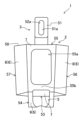
- FIG. 13 is a front view of a suspension device according to a seventh embodiment of the present invention in a pre-use state.
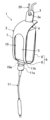
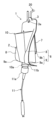
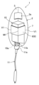
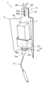
- FIG. 13 is a perspective view of a suspension device according to a seventh embodiment of the present invention in use.
- FIG. 13 is a front view of a suspension device according to a seventh embodiment of the present invention in use.
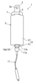
- FIG. 13 is a side view of a suspension device according to a seventh embodiment of the present invention in use.
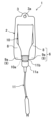
- FIG. 13 is a rear view of a suspension device according to embodiment 7 of the present invention in use.
- FIG. 27 is a view corresponding to FIG.
- FIG. 27 is a view corresponding to FIG. 26 according to a modified example.
- FIG. 27 is a view corresponding to FIG. 26 according to a modified example.
- FIG. 27 is a view corresponding to FIG. 26 according to a modified example.
- Fig. 1 shows a hanging device 1 according to a first embodiment of the present invention.
- the hanging device 1 is used to hang a container 10 for storing a nutrient (liquid) to be administered to a patient (not shown) during enteral nutrition from a gartle stand 20, and is made of paper.
- the container 10 suspended by the hanging device 1 has a body made of paper and is roughly rectangular (hexahedral) in shape, with the four adjacent sides in the circumferential direction of the body having the same width. In other words, the cross section of the body of the container 10 is roughly square.
- One longitudinal end face of the container 10 is inclined toward the surface of the container 10, and is provided with an outlet 10a to which the connector 11a of the medical tube 11 can be connected.
- an adapter 11b is attached to the outlet 10a.
- the connector 11a is connected to the outlet 10a via the adapter 11b.
- the hanging device 1 has a paper device body 2 that is strip-shaped (sheet-shaped) with flat front and back surfaces before use.
- a tongue-shaped hanging part 3 is provided at one end of the device body 2, which is used to hang the device from the garter stand 20.
- the hanging portion 3 is narrower than the rest of the device body 2, and a hanging hole 3a is formed near the tip.
- an engaging hole 4 is formed at the other end of the instrument body 2, and extends linearly in the width direction of the instrument body 2.
- the length of the engaging hole 4 corresponds to the width dimension of the suspended part 3, allowing the suspended part 3 to be inserted.
- an oval-shaped opening 5 is formed in the instrument body 2, extending in the longitudinal direction of the instrument body 2 from the middle to a position toward the other end.
- the instrument body 2 is designed to be bent toward the back side of the instrument body 2 when in use, and has a deformation portion 6 formed by bending and deforming the instrument body 2 toward the back side, and a base portion 7 formed from the area excluding the deformation portion 6.
- the deformation section 6 is provided with a holding section 8 formed in one end region of the device body 2 and holding the container 10 between the holding section 8 and the base section 7, and a support section 9 formed in the middle region of the device body 2 and supporting the container 10 from below.
- the base section 7 is formed in the other end region of the device body 2.
- the opening 5 of the device body 2 corresponds to the outlet 10a, and with the connector 11a of the medical tube 11 connected to the outlet 10a via the adapter 11b, the holding part 8 and the support part 9 are curved and deformed towards the back side to surround the container 10, and the suspended part 3 is inserted into the engaged hole 4 and its base is abutted against the periphery of the opening of the engaged hole 4, thereby engaging and connecting one end part and the other end part of the device body 2.
- the main body 2 When one end of the main body 2 is connected to the other end, the main body 2 becomes ring-shaped and is ready for use.
- the hanging hole 3a of the hanging part 3 is hooked onto the gartle stand 20, the body of the container 10 is sandwiched and held between the holding part 8 and the base part 7, and the support part 9 supports the area surrounding the outlet part 10a of the container 10 from below, so that the container 10 is hung from the gartle stand 20 and ready for use.
- the side of the container 10 is exposed at the portion of the opening 5 that corresponds to the other end region of the device body 2, and when the container 10 is attached to the device body 2 so that the surface of the container 10 faces the same direction as the surface of the device body 2, the contents indications and the like written on the surface of the container 10 can be visually confirmed.
- the container 10 not only the container 10 but also the hanging device 1 for hanging the container 10 is made of paper, which can greatly contribute to reducing the environmental impact.
- the hanging device 1 is in a sheet-like shape before use, so it does not take up much space when stored, and when in use, the device body 2 is simply bent at a specified position to create a portion for holding and supporting the container 10, making the hanging device 1 easy to handle.
- the device when a user uses the hanging device 1 of embodiment 1, the device can be used simply by bending and deforming the device body 2 and connecting the ends. In this way, the preparation work of deforming the device body 2 when in use is simplified, making the hanging device 1 easy to use.
- the dimension between the holding portion 8 and the base portion 7 and the length dimension of the support portion 9 can be changed, making it possible to change the size of the container 10 to be hung. Therefore, it can be used to hang multiple types of containers 10, making the hanging device 1 highly versatile.
- the outlet 10a is exposed through the opening 5, so the user can easily connect the connector 11a of the medical tube 11 to the outlet 10a, making the hanging device 1 easy to use.
- the support part 9 supports the surrounding area of the outlet part 10a of the container 10 from below when in use, the position of the outlet part 10a of the suspended container 10 is stabilized. This makes it possible to stabilize the transport state of the nutritional agent in the container 10 to the medical tube 11 during administration work.
- the surrounding area of the outlet part 10a means, for example, about 50% of the area centered on the outlet part 10a on the surface on which the outlet part 10a of the container 10 is provided. It is preferable that the device body 2 is configured to support at least a portion of the surrounding area of the outlet part 10a from below.
- the container 10 can be hung by hooking the hanging hole 3a onto the gartle stand 20, the hanging operation by the medical staff is simplified, and even if a force is suddenly applied to the container 10, the container 10 is less likely to come off the gartle stand 20, so the hanging state of the container 10 can be stabilized. Also, since the structure for hanging on the gartle stand 20 can be easily formed, processing costs can be kept low.
- the hanging device 1 of the first embodiment of the present invention is made of paper, but other types of materials may be used, such as cardboard or synthetic paper made for environmental protection purposes.
- the hanging device 1 may also be made of a plate-shaped thermoplastic resin material. In this case, it is possible to use less resin material than a hanging device that is integrally molded from a general resin material that has a three-dimensional structure even before use.
- one end portion and the other end portion of the tool body 2 are connected by inserting the suspended portion 3 into the engaged hole 4 to engage them, but this is not limited to the above.
- one end may be shaped like a hook to hook onto the other end, or they may be connected with adhesive or adhesive tape, etc.
- the instrument body 2 is put into a usable state by bending the deformable portion 6 of the instrument body 2 toward the back side and connecting one end portion with the other end portion, but the instrument body 2 may also be put into a usable state by bending the deformable portion 6 of the instrument body 2 toward the front side and connecting one end portion with the other end portion.
- the hanging portion 3 provided on one end of the instrument body 2 is narrower than the other regions, while an engaged hole 4 of a size corresponding to the narrow shaped hanging portion 3 is formed on the other end of the instrument body 2, and the hanging portion 3 is inserted into the engaged hole 4 to be in a usable state; however, this is not limited to the above, and for example, the other end of the instrument body 2 may be made wider than the other regions and an engaged hole 4 corresponding to the width dimension of the one end of the instrument body 2 is formed in the wider shaped portion, while the one end of the instrument body 2 is the hanging portion 3, and the hanging portion 3 is inserted into the engaged hole 4 to be in a usable state.
- the instrument body 2 is curved and deformed at the locations corresponding to the peripheral portions of one end face and the other end face in the longitudinal direction of the suspended container 10 to put it into a usable state, but this is not limited thereto.
- folding lines may be provided at the locations of the base part 7 corresponding to the peripheral portions of the other end face in the longitudinal direction of the suspended container 10, and at the locations between the base part 7 and the support part 9 or between the holding part 8 and the support part 9 corresponding to the peripheral portions of one end face in the longitudinal direction of the suspended container 10, and the instrument body 2 may be folded at the folding lines to put it into a usable state.
- Second Embodiment of the Invention 6 shows a hanging device 1 according to a second embodiment of the present invention.
- the structure of the area of the device body 2 that is bent during use is different from that of the first embodiment, so the same parts as those in the first embodiment are given the same reference numerals, and only the other different parts will be described.
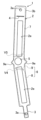
- the instrument body 2 of the second embodiment is strip-shaped before use and is shorter than the instrument body 2 of the first embodiment.
- the instrument body 2 of the second embodiment has a pair of slits 2a that extend side by side in the extension direction and are formed symmetrically in the width direction of the instrument body 2.
- the distance D1 between the two slits 2a from one end to the middle corresponds to the width of the outlet 10a of the container 10, while the distance D2 on the other end corresponds to the width of the main body of the container 10, and the middle of each slit 2a is gently curved to connect to the other end of the slit 2a.
- a mountain fold line 2b (fold line) is provided between one end of both slits 2a on the surface side of the device body 2.
- a semicircular hanging part 3 is provided in the center of the other longitudinal end of the device body 2, and a hanging hole 3a is formed through the center of the hanging part 3.
- the holding portion 8 in the second embodiment is formed in the middle of the outer area of each slit 2a in the device body 2.
- the support section 9 in the second embodiment is composed of a first support region 9a located on one end side of the outer region of each slit 2a in the device body 2, and a second support region 9b located on one end side between both slits 2a.
- the base portion 7 is formed in the other end region between the two slits 2a in the device body 2.
- the holding portion 8 and the first support region 9a are curved and deformed so that they jut out towards the front surface
- the second support region 9b is curved and deformed so that it juts out towards the back surface while folding along the mountain fold line 2b, thereby separating the holding portion 8 and the base portion 7 from each other, as shown in Figures 7 to 10.
- the container 10 is inserted between them so that the outlet part 10a of the container 10 is positioned between the first support areas 9a, and the connector part 11a of the medical tube 11 is connected to the outlet part 10a via the adapter 11b.
- the hanging hole 3a of the suspended part 3 is hooked onto the gartle stand 20. This causes the body part of the container 10 to be held between the holding part 8 and the base part 7, and the support part 9 to support the surrounding part of the container 10 around the outlet part 10a from below, and the container 10 is then hung from the gartle stand 20 and ready for use.
- the holding portion 8 holds the container 10 at a distance on both sides in the width direction, so that the contents indication etc. written on the surface of the container 10 can be visually confirmed when the container 10 is attached to the device body 2 with the surface of the container 10 facing the same direction as the surface of the device body 2. Therefore, the user can check the type etc. of the container 10 even after starting the administration operation.
- the amount of deformation in each area of the device body 2 can be changed to change the dimension between the holding portion 8 and the base portion 7 and the length dimension of the support portion 9, making it possible to change the size of the container 10 to be hung. Therefore, it can be used to hang multiple types of containers 10, making the hanging device 1 highly versatile.
- the outlet 10a is exposed from a location separated from the support 9, allowing the user to easily connect the connector 11a of the medical tube 11 to the outlet 10a, resulting in a suspension device 1 that is easy to use.
- the holding portion 8 and the support portion 9 are provided with a mountain fold line 2b that serves as the starting point for bending and deforming the holding portion 8 and the support portion 9, so the bending position in the holding portion 8 and the support portion 9 is clear and easy to bend. Therefore, medical personnel can efficiently change the hanging device 1 from a pre-use state to a use state without spending a lot of time.
- the device body 2 in the first and second embodiments of the present invention is band-shaped before use, but this is not limited thereto, and it may be, for example, square or elliptical.
- Third Embodiment of the Invention 11 shows a hanging device 1 according to a third embodiment of the present invention.
- the outer shape of the device body 2 and the structure of the portion of the device body 2 that is bent during use are different from those in the first embodiment, so the same parts as those in the first embodiment are given the same reference numerals, and only the other different parts will be described.
- the device body 2 of the third embodiment has an elliptical sheet shape before use.
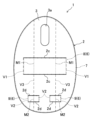
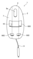
- a pair of first slits 2c extending side by side at a predetermined interval are formed in the central part of the width direction of the device body 2, and the holding portion 8 of the third embodiment is formed between the first slits 2c.
- a first mountain fold line M1 (fold line) is provided in the center of the surface side of the holding portion 8, extending in the direction in which both first slits 2c are arranged side by side, while a first valley fold line V1 (fold line) is provided at each continuous portion of the surface side of the holding portion 8 with the base portion 7, extending in the same direction as the first mountain fold line M1.
- the dimensions between the first mountain fold line M1 and each of the first valley fold lines V1 correspond to the width dimensions of the sides of the container 10.
- a pair of second slits 2d are formed in the widthwise center of the device body 2 and on one side of the two first slits 2c in the juxtaposition direction, extending parallel to the first slits 2c in the same direction, and the support portion 9 of the third embodiment is formed between the two second slits 2d.
- the length of the second slit 2d is set to approximately 1/3 of the length of the first slit 2c.
- a second mountain fold line M2 (fold line) extending in the same direction as the first mountain fold line M1 is provided at a position corresponding to the first mountain fold line M1 on the surface side of the support portion 9, while a second valley fold line V2 (fold line) extending in the same direction as the second mountain fold line M2 is provided at each continuous portion with the base portion 7 on the surface side of the support portion 9.
- the hanging portion 3 is provided in the widthwise center of the device body 2 and in the area on the other side of the arrangement direction of the first slits 2c, and a rectangular hanging hole 3a extending in the widthwise direction of the device body 2 is formed in the center of the hanging portion 3.
- a third valley fold line V3 (folding line) is provided at a position corresponding to the first mountain fold line M1 on the surface side of the base portion 7, and extends in the same direction as the first mountain fold line M1.
- the holding portion 8 When the device body 2 is in use, as shown in Figures 12 to 15, the holding portion 8 is mountain folded at the first mountain fold line M1 and valley folded at each of the first valley fold lines V1, thereby bending and deforming the holding portion 8 so that it juts out toward the front surface side, and the periphery of the holding portion 8 of the base portion 7 is valley folded at the third valley fold line V3, thereby bending and deforming the holding portion 8 and the base portion 7 so that it juts out toward the back surface side, thereby separating the holding portion 8 and the base portion 7 from each other.
- the area enclosed by the holding part 8 and the base part 7 becomes roughly square in shape, corresponding to the cross section of the main body of the container 10, so that the container 10, with the connector part 11a of the medical tube 11 connected to the outlet part 10a, can be inserted between the holding part 8 and the base part 7 so that the outlet part 10a is on the support part 9 side.
- the support part 9 is mountain folded at the second mountain fold line M2 and valley folded at each second valley fold line V2 to fold and deform so that it overhangs the front side, and the periphery of the support part 9 of the base part 7 is valley folded at the third valley fold line V3 to fold and deform so that it overhangs the back side, contacting the peripheral part of the pouring outlet part 10a of the container 10, and when the hanging hole 3a of the hanging part 3 is hooked onto the gartle stand 20, the main body part of the container 10 is sandwiched and held between the holding part 8 and the base part 7, and the peripheral part of the pouring outlet part 10a of the container 10 is supported from below by the support part 9, and the container 10 is hung from the gartle stand 20 and ready for use.
- the support portion 9 supports the container 10 from below with the holding portion 8 and the base portion 7 surrounding the entire side of the container 10. This makes it possible to prevent the container 10 from accidentally coming off the hanging fixture 1, and to prevent the container 10 from falling off the hanging fixture 1.
- the area enclosed by the holding portion 8 and the base portion 7 is roughly square in shape, corresponding to the cross section of the main body of the container 10, so that when the container 10 is held by the holding portion 8 and the base portion 7, the container 10 does not shift relative to the device body 2. This makes it possible to stabilize the attachment state of the container 10 to the hanging device 1, and reliably prevents the container 10 from falling off the hanging device 1.
- the continuous portion between the deformation portion 6 (holding portion 8 and support portion 9) and the base portion 7 has a first valley fold line V1 and a second valley fold line V2 which serve as starting points for bending and deforming the deformation portion 6, and the deformation portion 6 has a first mountain fold line M1 and a second mountain fold line M2 which serve as starting points for bending and deforming the deformation portion 6, so that the continuous portion between the deformation portion 6 and the base portion 7 and the bending position in the deformation portion 6 are clear and easy to bend. Therefore, medical personnel can efficiently change the hanging device 1 from a pre-use state to a use state without spending a lot of time.
- the pair of first slits 2c and second slits 2d are formed in the center of the width of the device body 2, but they may be formed in other positions.
- Fourth embodiment of the invention 16 shows a hanging device 1 according to a fourth embodiment of the present invention.
- the only differences from the third embodiment are the outer shape of the device body 2 and the shape of the hanging hole 3a, the number of support parts 9, and the structure of the area where the device body 2 is bent during use.
- the other parts are the same as those in the third embodiment, so the same reference numerals are used to denote the same parts as in the third embodiment, and only the other differences will be described.
- the device body 2 of embodiment 4 is in the form of an elliptical sheet that is longer in length than the device body 2 of embodiment 3 before use. Also, the hanging hole 3a of embodiment 4 is in the form of an ellipse that extends in the longitudinal direction of the device body 2.
- a pair of first mountain fold lines M1 are provided on the surface side of the holding portion 8, and the dimension between the first mountain fold lines M1 corresponds to the width dimension of the side of the container 10.
- the dimension between adjacent first mountain fold lines M1 and first valley fold lines V1 on one side of the width direction of the instrument body 2 is set to be the same as the dimension between adjacent first mountain fold lines M1 and first valley fold lines V1 on the other side of the width direction of the instrument body 2.
- the support portions 9 are provided in pairs at a predetermined interval in the extension direction of the second slit 2d, and each support portion 9 is located in a position corresponding to each of the first mountain fold lines M1.
- the second mountain fold lines M2 are provided at the center of the front surface side of each support part 9, and are located in positions corresponding to the first mountain fold lines M1.
- the second valley fold lines V2 are provided at each continuous portion between the base portion 7 and the surface side of the support portion 9, and extend in the same direction as the second mountain fold lines M2.
- the third valley fold lines V3 are provided at positions corresponding to the first mountain fold lines M1 on the surface side of the base portion 7, and extend in the same direction as the first mountain fold lines M1.
- the holding portion 8 When the device body 2 is in use, as shown in Figures 17 to 20, the holding portion 8 is mountain-folded at each of the first mountain fold lines M1 and valley-folded at each of the first valley fold lines V1, thereby bending and deforming the holding portion 8 so that it juts out toward the front surface side, and the periphery of the holding portion 8 of the base portion 7 is valley-folded at each of the third valley fold lines V3, thereby bending and deforming the holding portion 8 and the base portion 7 so that it juts out toward the back surface side, thereby separating the holding portion 8 and the base portion 7 from each other.
- the dimension between the first mountain fold lines M1 of the holding part 8 corresponds to the width dimension of the side of the container 10, so that the container 10, with the connector part 11a of the medical tube 11 connected to the outlet part 10a, can be inserted between the holding part 8 and the base part 7 so that the surface of the main body part of the container 10 faces the surface side of the device body 2 and the outlet part 10a is on the support part 9 side.
- each support part 9 is mountain folded at the second mountain fold line M2 and valley folded at each second valley fold line V2 to bend and deform so that it juts out towards the front side, and the periphery of each support part 9 of the base part 7 is valley folded at each third valley fold line V3 to bend and deform so that it juts out towards the back side, contacting the periphery of the spout part 10a of the container 10, and when the hanging hole 3a of the hanging part 3 is hooked onto the gartle stand 20, the main body of the container 10 is sandwiched and held between the holding part 8 and the base part 7, and the container 10 is hung from the gartle stand 20 with each support part 9 supporting both sides of the width direction of the periphery of the spout part 10a of the container 10 from below, and is ready for use.
- the surface of the four sides of the container 10 can be attached so that it faces the same direction as the surface side of the device body 2. Therefore, in the case where the surface including the outlet portion 10a is inclined toward the surface of the container 10, as in the case of the container 10 suspended in the fourth embodiment of the present invention, when the container 10 is attached to the device body 2 and the hanging device 1 is suspended, the device body 2 will be inclined diagonally toward its back side so that the container 10 moves directly below the suspension position, but accordingly the surface including the outlet portion 10a will be in a position extending approximately horizontally. This reduces the amount of liquid remaining in the container 10 at the end of administration, and the liquid in the container 10 can be used without waste.
- the support parts 9 support the container 10 from below at two separate positions on both sides of the container 10 in the width direction, so that when the container 10 is attached to the hanging device 1, the position of the container 10 relative to the device body 2 can be stabilized.
- Fifth embodiment of the invention 21 shows a hanging device 1 according to a fifth embodiment of the present invention.
- the outer shape of the device body 2 and the structure of the area where the device body 2 is bent during use are different from those of the first embodiment, so the same parts as those of the first embodiment are given the same reference numerals, and only the other different parts will be described.
- the device body 2 of the fifth embodiment has a hanging portion 3 at one end.
- the hanging portion 3 is narrower than the other areas of the device body 2, and a hanging hole 3a is formed through the hanging portion 3 at a position near the tip.
- another hanging part 3b is provided at the other end of the device body 2.
- a hanging hole 3a is formed through the other hanging part 3b at a position near the tip.
- the hanging holes 3a provided in the hanging part 3 and the other hanging part 3b are each circular.
- the other hanging part 3 has an engaged hole 4 that extends linearly in the width direction of the device body 2.
- the length of the engaged hole 4 is greater than the width dimension of the hanging part 3. This allows the hanging part 3 to be inserted into the engaged hole 4.
- the instrument body 2 is designed to be bent toward the front surface of the instrument body 2 when in use.
- the instrument body 2 has a deformed portion 6 formed by bending the instrument body 2 toward the front surface, and a base portion 7 formed from the area excluding the deformed portion 6. Note that the instrument body 2 does not necessarily need to be bent, and may be curved toward the front surface.
- the deformation section 6 is provided with a holding section 8 that is formed in one end region of the device body 2 and that holds the container 10 between it and the base section 7, and a support section 9 that is formed in the middle region of the device body 2 and that supports the container from below.
- the base section 7 is formed in the other end region of the device body 2.
- the holding portion 8 is inclined so that it is positioned to one side in the width direction as it approaches one end. Furthermore, a rectangular support hole 2e is provided in each of the holding portion 8 and the base portion 7. In the fifth embodiment of the present invention, the support hole 2e is shown as a rectangular through hole, but the support hole 2e may be a slit, or may be a tongue-shaped hole in which one side of the rectangle is not cut out from the device body 2 and the other three sides are cut out.
- the support portion 9 has a circular opening 5.
- the support portion 9 also has a marker portion 9e that protrudes from both sides in the width direction.
- the marker portion 9e is generally triangular in shape.
- a fourth valley fold line (folding line) is provided at the connecting portion between the holding portion 8 and the support portion 9 on the surface side of the instrument body 2, and extends at an angle toward one end of the instrument body 2 as it approaches one side in the width direction.
- a fifth valley fold line (folding line) is provided at the connecting portion between the support portion 9 and the base portion 7 on the front side of the device body 2, and extends at an angle toward one side in the width direction so as to be positioned toward the other end side of the device body 2.
- the device body 2 is adapted to be valley folded at the fourth valley fold line V4 and the fifth valley fold line V5.
- the device body 2 is transformed from a sheet-like shape into a U-shape by being valley folded at the fourth valley fold line V4 and the fifth valley fold line V5.
- the U-shaped instrument body 2 is inserted into the support hole 2e of the base part 7 and the support hole 2e of the holding part 8 with the opening 5 corresponding to the outlet part 10a (with the outlet part 10a inserted into the opening 5).
- the U-shaped instrument body 2 is inserted into the support hole 2e of the base part 7 and the support hole 2e of the holding part 8 with the opening 5 corresponding to the outlet part 10a (with the outlet part 10a inserted into the opening 5).
- the marker part 9e it becomes easy to insert the body part of the container 10 into the support hole 2e.
- the instrument body 2 is surrounded with the connector part 11a of the medical tube 11 connected to the outlet part 10a of the instrument body 2, and the suspended part 3 is inserted into the engaged hole 4, and one end part of the instrument body 2 (suspended part 3) and the other end part of the instrument body 2 (other suspended part 3b) are abutted against each other to engage and connect the two ends, and the instrument body 2 becomes annular and is ready for use.
- the holding part 8 and the base part 7 hold the main body of the container 10, and the support part 9 supports the surrounding part of the pouring outlet part 10a of the container 10 from below, so that the container 10 can be hung from the gartle stand 20 and used.
- the main body portion of the container 10 is inserted into the support hole 2e of the holding part 8 and the support hole 2e of the base part 7. This allows the four sides of the container 10 to be supported by the support part 9 and the base part 7, preventing the container 10 from falling off the hanging device 1.
- the two hanging holes 3a provided in the hanging device 1 are hooked onto the hanging body. This prevents the hanging device 1 from coming off the hanging body due to sudden application of force to the hanging device 1, and prevents the container 10 from falling together with the hanging device 1.
- the device body 2 is deformed from a sheet-like shape into a U-shape by folding the holding portion 8 and the support portion 9 at the fourth valley fold line V4 and the fifth valley fold line V5, and then the device body 2 is set in the container 10 so that the opening 5 corresponds to the spout 10a (the spout 10a is inserted into the opening 5).
- the device body 2 in a sheet-like state may be set in the container 10 so that the opening 5 corresponds to the spout 10a, and then the device body 2 may be deformed from a sheet-like shape into a U-shape by folding the fourth valley fold line V4 and the fifth valley fold line V5.
- the device body 2 is deformed by folding the fourth valley fold line V4 and the fifth valley fold line V5, but the device body 2 may be deformed so that it is curved without forming any fold lines.
- the support hole 2e is provided in each of the support portion 9 and the base portion 7, but the support hole 2e may be provided in only one of the support portion 9 and the base portion 7.
- the marker portion 9e is provided on both sides of the support portion 9 in the width direction, but the marker portion 9e may be provided on only one side of the support portion 9 in the width direction.
- Sixth embodiment of the invention 23 shows a hanging device 1 according to a sixth embodiment of the present invention.
- the outer shape of the device body 2 and the structure of the area where the device body 2 is bent during use are different from those of the first embodiment, so the same parts as those of the first embodiment are given the same reference numerals, and only the other different parts will be described.
- the instrument body 2 of embodiment 6 is in the shape of a generally rectangular sheet before use.
- a pair of third slits 2f extending side by side at a predetermined interval are formed in the widthwise central portion of the instrument body 2.
- the holding portion 8 of embodiment 6 is formed between both third slits 2f.
- the support portion 9 of embodiment 6 is formed by the end portion of the holding portion 8 on the other end side of the instrument body 2 (the end portion on the other side in the juxtaposition direction of both third slits 2f in the holding portion 8).
- a pair of third mountain fold lines M3 (folding lines) extending in the direction in which both third slits 2f are arranged side by side are provided at the center of the surface side of the holding portion 8 at a predetermined interval in the width direction.
- the dimension between the pair of third mountain fold lines M3 corresponds to the width dimension of the side surface of the container 10.
- a sixth valley fold line V6 fold line
- the seventh valley fold lines are provided at positions corresponding to the third mountain fold lines M3 on the surface side of the base portion 7, and extend in the same direction as the third mountain fold lines M3.
- the suspended part 3 in the sixth embodiment is provided at the other end of the main body 2.
- the suspended part 3 is narrower than the other areas of the main body 2.
- the suspended part 3 is provided with a first suspended part 51 and a second suspended part 52.
- the first hanging part 51 has a first hanging hole 51a formed therethrough.
- the second hanging part 52 has a second hanging hole 52a formed therethrough.
- the first hanging hole 51a and the second hanging hole 52a are elliptical in shape and extend in the direction in which the two third slits 2f are arranged side by side.
- a fourth mountain fold line M4 (fold line) extending in the width direction is provided at the connecting portion between the first suspended part 51 and the second suspended part 52.
- a fifth mountain fold line M5 (folding line) is provided at one end of the fourth mountain fold line M4, extending in the width direction.
- the first suspended part 51 is mountain-folded at the fourth mountain fold line M4 so that the first suspended part 51 and the second suspended part 52 overlap, and the first hanging hole 51a and the second hanging hole 52a are aligned.
- the holding portion 8 When the device body 2 is in use, the holding portion 8 is mountain-folded at each of the third mountain fold lines M3 and valley-folded at each of the sixth valley fold lines V6, thereby bending and deforming the holding portion 8 so that it juts out toward the front surface side, and the periphery of the holding portion 8 of the base portion 7 is valley-folded at each of the seventh valley fold lines V7, thereby bending and deforming the holding portion 8 so that it juts out toward the back surface side, thereby separating the holding portion 8 and the base portion 7 from each other.
- the dimension between the third mountain fold lines M3 of the holding portion 8 corresponds to the width dimension of the side of the container 10, so that the container 10, with the connector portion 11a of the medical tube 11 connected to the outlet portion 10a, can be inserted between the holding portion 8 and the base portion 7 so that the surface of the main body of the container 10 faces the surface of the instrument body 2.
- the container 10 when the container 10 is inserted between the holding portion and the base portion 7 in a forward tilted position (the outlet portion 10a side of the container 10 is in the rear position and the side opposite the outlet portion 10a of the container 10 is in the front position), the main body of the container 10 is held by the holding portion 8 and the base portion 7, and the container 10 is suspended from the gartle stand 20 with the main body portion (side portion) of the container 10 supported from below by the support portion 9 formed by the upper end portion of the holding portion 8, and is in a usable state.
- another support part 2g which is formed by a part of the base part 7 located on one end side of the holding part 8, supports one longitudinal end face part of the container 10 from below (see FIG. 25).
- the third slit 2f makes it possible to provide the holding portion 8 and the support portion 9. This eliminates the need to provide a separate slit for the support portion, for example, and therefore makes it possible to keep the processing costs of the hanging device 1 low.
- the container 10 when the container 10 is hung on a hanging body such as the garter stand 20, the first hanging hole 51a and the second hanging hole 52a provided in the hanging device 1 are hooked onto the hanging body. This prevents the hanging device 1 from coming off the hanging body due to an unexpected force being applied to the hanging device 1, causing the container 10 to fall together with the hanging device 1.
- the holding portion 8, the support portion 9, and the base portion 7 are bent to place the device body 2 in a usable state, but the device body 2 can also be bent to place the device body 2 in a usable state.
- the outer shape of the device body 2 in the third and fourth embodiments of the present invention is elliptical before use, but this is not limited thereto and may be rectangular or circular.
- the container 10 is hung by hooking the hanging hole 3a formed in the device body 2 onto the garter stand 20, but this is not limited to the above.
- a hook-shaped area may be formed in the device body 2 and hung by hooking it onto the garter stand 20.
- the hanging hole 3a is circular, but it may be rectangular or elliptical.
- a cutout portion that is arc-shaped (J-shaped) when viewed from the front and opens at one longitudinal end of the device body 2 may be formed, and the container 10 may be hung by hooking the cutout portion onto the gartle stand 20.
- a C-shaped slit may be formed in the region on one longitudinal end side of the device body 2, and the hanging hole 3a may be formed by bending the inner region of the slit from the continuous portion with the outer region of the slit as the starting point during use.
- the medical tube 11 has a connector portion 11a, and the connector portion 11a is connected to the outlet portion 10a of the container 10 via an adapter 11b.
- the hanging device 1 of the present invention can be used without the adapter 11b, or even if the medical tube 11 is connected to the container 10 with a funnel-shaped soft member.
- the cross section of the main body of the container 10 is approximately square, but this is not limited thereto. Even if the cross section of the main body of the container 10 is polygonal, such as rectangular or octagonal, the container 10 can be suspended by the hanging device 1 of the present invention by appropriately changing the shape of the device body 2 to match these shapes.
- the hanging device 1 of the present invention is used to hang the container 10 containing the nutritional agent when providing enteral nutrition, but the present invention is not limited to this and can also be used to hang a container in an infusion line for administering medicinal liquids to a patient.
- Fig. 26 shows a hanging device 1 according to a seventh embodiment of the present invention.
- the hanging device 1 of the seventh embodiment includes a paper device body 2 having a flat band-like (sheet-like) surface and an inverted T-shape when viewed in the thickness direction.
- the device body 2 includes a hanging portion 3, an opening 5, a deformation portion 6, and a base portion 7.
- the deformation portion 6 includes a holding portion 8 and a support portion 9.
- the hanging part 3 is provided at the other longitudinal end of the main body 2, and is narrower than other areas of the main body 2.
- the hanging part 3 is provided with a first hanging part 51 having a first hanging hole 51a formed therethrough, and a second hanging part 52 having a second hanging hole 52a formed therethrough.
- the first hanging hole 51a and the second hanging hole 52a are provided so as to be hung from the garter stand 20.
- the first hanging hole 51a and the second hanging hole 52a are oval shaped to make them easier to hang on a hook or the like of the garter stand 20.
- a back surface portion 53, a bottom surface portion 54, and a front surface portion 55 are provided in succession in the longitudinal direction of the device body 2 at one end of the hanging portion 3.
- the opening 5 has a generally tongue-like shape and is continuous from the bottom surface 54 to the front surface 55.
- the front surface 55 is provided with a window 55a having a substantially rectangular shape.
- the window 55a is provided at a predetermined distance from the opening 5 in the longitudinal direction of the device body 2.
- a connecting portion 55b is provided between the opening 5 and the window 55a in the front surface 55, connecting the left and right portions of the front surface 55 in the width direction.
- a left side surface portion 56 is provided contiguous to one end of the front surface portion 55 in the width direction intersecting the longitudinal direction of the device body 2.
- a right side surface portion 57 is provided contiguous to the front surface portion 55 in the other end of the front surface portion 55 in the width direction of the device body 2.
- the left side surface portion 56 and the right side surface portion 57 are shaped like wings extending from the front surface portion 55 on both sides in the width direction.
- the left side surface portion 56 is inclined toward one end in the width direction so that it is positioned toward the other end in the longitudinal direction.
- a left adhesive surface portion 56a is provided at one end in the width direction of the left side surface portion 56.
- the right side surface portion 57 is inclined toward the other end in the longitudinal direction as it approaches the other end in the width direction.
- a right adhesive surface portion 57a is provided at the other end in the width direction of the right side surface portion 57.
- adhesive e.g., glue
- glue is applied to the left adhesive surface portion 56a and the right adhesive surface portion 57a.
- the bottom surface portion 54, the left side surface portion 56, and the right side surface portion 57 form the deformation portion 6. Furthermore, of the deformation portion 6, the bottom surface portion 54 forms the support portion 9, and the remaining left side surface portion 56 and right side surface portion 57 of the deformation portion 6 form the holding portion 8. Furthermore, the back surface portion 53 and the front surface portion 55 form the base portion 7.
- the surface side of the instrument body 2 is provided with a first horizontal fold line W1, a second horizontal fold line W2, a third horizontal fold line W3, a fourth horizontal fold line W4, and a fifth horizontal fold line W5 extending in the width direction (horizontal direction) of the instrument body 2.
- the surface side of the instrument body is provided with a first vertical fold line L1, a second vertical fold line L2, a third vertical fold line L3, a fourth vertical fold line L4, a fifth vertical fold line L5, and a sixth vertical fold line L6 extending in the longitudinal direction (vertical direction) of the instrument body 2.
- the third horizontal fold line W3, the fourth horizontal fold line W4, the fifth horizontal fold line W5, the first vertical fold line L1, the second vertical fold line L2, the third vertical fold line L3, the fourth vertical fold line L4, the fifth vertical fold line L5 and the sixth vertical fold line L6 function as fold lines that serve as starting points for bending and deforming the deformation portion 6 (the bottom surface portion 54, the left side surface portion 56 and the right side surface portion 57).
- the first horizontal fold line W1 is provided at the continuous portion between the first suspended part 51 and the second suspended part 52.
- the second horizontal fold line W2 is provided at one longitudinal end of the second hanging hole 52a in the second hanging part 52.
- the second horizontal fold line W2 is also provided on the other longitudinal end side of the continuous part between the second hanging part 52 and the back part 53. This makes the second horizontal fold line W2 easier to bend than if it were provided at the continuous part between the second hanging part 52 and the back part 53, and also makes it less likely that the device body 2 will break at the second horizontal fold line W2 into the part on the hanging part 3 side and the part on the back part 53 side.
- the third horizontal fold line W3 is located at the connecting portion between the back surface portion 53 and the bottom surface portion 54.
- the fourth horizontal fold line W4 is provided in the middle of the bottom surface portion 54.
- the fourth horizontal fold line W4 is provided on both sides of the opening 5 in the width direction. In other words, the fourth fold line W4 is divided by the opening 5.
- the fifth horizontal fold line W5 is located at the connecting portion between the bottom surface portion 54 and the front surface portion 55.
- the first vertical fold line L1 is located at the connecting portion between the front portion 55 and the left side portion 56.
- the second vertical fold line L2 is located midway through the left side surface portion 56.
- the third vertical fold line L3 is provided on one widthwise end side of the second vertical fold line L2.
- the fourth vertical fold line L4 is located at the connecting portion between the front portion 55 and the right side portion 57.
- the fifth vertical fold line L5 is located midway through the right side surface portion 57.
- the sixth vertical fold line L6 is provided on the other widthwise end side of the fifth vertical fold line L5.
- the left adhesive surface 56a is attached to the back surface of one end of the back surface 53 in the width direction
- the right adhesive surface 57a is attached to the back surface of the other end of the back surface 53 in the width direction (see Figure 31).
- the left adhesive surface portion 56a of the left side portion 56 is attached to the back portion 53 at a position where the third vertical fold line L3 of the left side portion 56 coincides with one widthwise end of the back portion 53. This allows the third vertical fold line L3 to be provided at the continuous portion between the back portion 53 and the left side portion 56.
- the right adhesive surface portion 57a of the right side portion 57 is attached to the back portion 53 at a position where the sixth vertical fold line L6 of the right side portion 57 coincides with the other widthwise end of the back portion 53. This allows the sixth vertical fold line L6 to be provided at the continuous portion between the back portion 53 and the right side portion 57.
- the first hanging part 51 is folded at the first horizontal fold line W1 so that the first hanging part 51 and the second hanging part 52 overlap, and the first hanging hole 51a and the second hanging hole 52a are aligned.
- the first hanging part 51 and the second hanging part 52 are bonded together using an adhesive (e.g., glue).
- the instrument body 2 in the pre-use state is folded (valley folded) at the fourth horizontal fold line W4, the second vertical fold line L2, and the fifth vertical fold line L5.
- the instrument body 2 in the pre-use state is configured to be in the shape of a folded double sheet.
- the bottom portion 54 is folded approximately in half between one end portion and the other end portion in the longitudinal direction along the fourth horizontal fold line W4, so that the portions folded approximately in half overlap in the thickness direction
- the left side portion 56 is folded approximately in half between one end portion and the other end portion in the width direction along the second vertical fold line L2, so that the portions folded approximately in half overlap in the thickness direction
- the right side portion 57 is folded approximately in half between one end portion and the other end portion in the width direction along the fifth vertical fold line L5, so that the portions folded approximately in half overlap in the thickness direction.
- the device body 2 before use is not folded at the third horizontal folding line W3, the fifth horizontal folding line W5, the first vertical folding line L1, the third vertical folding line L3, the fourth vertical folding line L4, and the sixth vertical folding line L6.
- a number of pre-use instrument bodies 2 are stacked in the thickness direction in a production facility and packed in a packaging box (e.g., cardboard, etc., not shown) and shipped to a hospital or the like. Then, in the hospital or the like, a medical professional takes out the pre-use instrument body 2 (hanging instrument 1) from the packaging box and uses it.
- a packaging box e.g., cardboard, etc., not shown
- the tool body 2 (hanging tool 1) in the used state is folded (valley folded) at the third horizontal fold line W3, the fifth horizontal fold line W5, the first vertical fold line L1, the third vertical fold line L3, the fourth vertical fold line L4, and the sixth vertical fold line L6.
- the tool body 2 (hanging tool 1) in the used state is box-shaped, forming a space capable of housing the container 10 inside the tool body 2 by expanding the folded portion of the tool body 2 in the pre-use state.
- the tool body 2 in the used state has an upper opening 58 in a substantially rectangular shape formed in its internal space, which is used for inserting and removing the container 10.
- the device body 2 has fold lines so that it can be easily folded and easily unfolded from the folded state for use, but the fold lines can be omitted as appropriate.
- the first vertical fold line L1 and the fourth vertical fold line L4 can be omitted, and the boundary between the front portion 55 and the left side portion 56, or the front portion 55 and the right side portion 57, can be curved and deformed without folding.
- the container 10 is attached to the device body 2 so that it is sandwiched between the front portion 55 and the back portion 53.
- the instrument body 2 in the used state is folded (valley folded) at the fourth horizontal fold line W4, but the bottom surface portion 54 is wider than the instrument body 2 in the pre-use state.
- the instrument body 2 in the used state is folded (valley folded) at the second vertical fold line L2 and the fifth vertical fold line L5, but the left side surface portion 56 and the right side surface portion 57 are wider than the instrument body 2 in the pre-use state.
- the hanging device 1 is folded (mountain folded) at the second horizontal fold line W2, so that the hanging portion 3 is folded toward the outer surface of the back surface 53.
- the container 10 is placed on a table or the like (not shown) with the outlet 10a positioned at the top. Then, the box-shaped device body 2 in use is placed over the container 10 from above with the upper opening 58 facing downward, so that the outlet 10a of the container 10 is inserted into the opening 5.
- the opening 5 is provided continuously from the bottom surface 54 to the front surface 55, in other words, the opening 5 is provided continuously from the bottom surface 54 to the front surface 55 beyond the boundary between the bottom surface 54 and the front surface 55, so that when the outlet 10a is inserted into the opening 5, interference between the outlet 10a and the opening 5 can be suppressed.
- the device body 2 is set such that the dimension between the second horizontal bending line W2 and the third horizontal bending line W3 is smaller than the vertical dimension of the container 10, so that the outlet 10a of the container 10 can be reliably inserted into the opening 5.
- the dimension between the second horizontal folding line W2 and the third horizontal folding line W3 of the device body 2 in the use state is shorter than the vertical dimension of the container 10, so that when the container 10 is placed on a table or the like with the spout 10a positioned on the upper side, the side of the other longitudinal end face of the container 10 (the face of the container 10 in contact with the table or the like) is exposed from the device body 2.
- the bottom face portion 54 of the device body 2 comes into contact with one longitudinal end face of the container 10 (the face on which the spout 10a is provided) due to gravity. This makes it possible to reliably insert the spout 10a of the container 10 into the opening 5.
- the suspended portion 3 is folded toward the outer surface side of the back portion 53 at the second horizontal folding line W2, it is possible to suppress interference of the suspended portion 3 with the upper surface of the table or the like when the device body 2 is placed over the container 10. This prevents the suspended part 3 from bouncing off if it comes into contact with the top surface of a table or the like, and prevents the position of the device body 2 from changing in a direction that would tip the container 10 over.
- the lid (not shown) attached to the outlet 10a is removed, and an adapter 11b is attached to the outlet 10a.
- the connector 11a of the medical tube 11 is then connected to the adapter 11b.
- the container 10 is then rotated approximately 180 degrees so that the outlet 10a, which is located at the top, is now located at the bottom, and the first hanging hole 51a and the second hanging hole 52a of the suspended part 3 are then hooked onto the hooks of the gartle stand 20, allowing the container 10 to be hung from the gartle stand 20 using the hanging device 1.
- the bottom surface 54 of the device body 2 is configured to support the container 10 from below.
- the bottom surface 54 of the device body 2 is configured to support the surrounding area of the spout 10a from below.
- the back part 53, front part 55, left side part 56, and right side part 57 of the device body 2 are configured to support the container 10 from the sides.
- the device body 2 contains a resin material (for example, a thermoplastic resin such as polypropylene or polyethylene terephthalate), due to the nature of the resin material, the device body 2 rebounds when the folded device body 2 is unfolded.
- the left side part 56 and right side part 57 of the device body 2 in the used state are in a more expanded state than in the pre-use state, but the left side part 56 and right side part 57 are not completely expanded (see FIG. 28 and FIG. 29).
- the gap between the back part 53 and the front part 55 is smaller than the front-to-rear dimension of the container 10, so when the container 10 is stored in the device body 2, the container 10 is sandwiched between the back part 53 and the front part 55. Therefore, the container 10 can be securely held between the rear part 53 and the front part 55 of the device body 2.
- a window portion 55a is provided on the front portion 55 of the device body 2, but the device body 2 may be made of a transparent or translucent material and may not need to have a window portion 55a.
- the shape of the device before use is a folded double sheet, which makes it possible to store the device without taking up too much space, while at the same time, when in use, the folded device body 2 is simply unfolded, making the hanging device 1 easy to handle.
- the entire device is made from paper, which contributes greatly to reducing the environmental impact.
- the position of the outlet 10a of the suspended container 10 becomes stable, so the transport state of the liquid in the container 10 to the medical tube 11 during administration can be stabilized.
- the folded portion of the device body 2 is unfolded to become box-shaped, forming a space inside the device body 2 capable of housing the container 10.
- This box-shaped device body 2 makes it possible to stably support the container 10 housed within the space. Therefore, when the container 10 is suspended, it is possible to prevent the container 10 from falling off the device body 2.
- the container 10 when the container 10 is housed within the space of the device body 2 during use, the container 10 is supported by the back surface 53, front surface 55, left side surface 56, right side surface 57, and bottom surface 54.
- the device body 2 can stably support the container 10, and it is possible to prevent the container 10 from falling off the device body 2 when hanging the container 10.
- the outlet portion 10a faces the opening 5 when hanging the container 10, the user can easily connect the medical tube 11 to the outlet portion 10a, making it possible to create a hanging device that is comfortable to use.
- the device body 2 can be easily folded and easily unfolded from the folded state for use.
- the fifth horizontal fold line W5 provided at the continuous portion between the bottom surface portion 54 and the front surface portion 55 can be made short. This makes it easier to fold the device body 2 at the fifth horizontal fold line W5. Also, since the opening 5 can be made wide, the spout portion 10a of the container 10 can be attached to the hanging device 1 without touching the device body 2, which is hygienic.
- a gap is provided between the opening 5 and the window 55a; in other words, a connecting portion 55b is provided between the opening 5 and the window 55a to connect the left and right portions of the front surface 55.
- the container can be hung by hooking the first hanging hole 51a and the second hanging hole 52a onto a hanging body such as a garter stand 20 placed in a medical facility.
- a hanging body such as a garter stand 20 placed in a medical facility.
- the continuous portion between the deformation portion 6 and the base portion 7, and the bending position in the deformation portion 6, are clearly defined and easy to bend. Therefore, medical personnel can change the suspension device 1 from a pre-use state to a use state efficiently without spending a lot of time.
- the first hanging hole 51a and the second hanging hole 52a provided in the hanging device 1 are hooked onto the hanging body. This prevents the hanging device from coming off the hanging body due to sudden application of force to the hanging device, causing the container to fall together with the hanging device.
- the other end portion of the back surface portion 53 has a larger width dimension than the one end portion
- the one end portion of the front surface portion 55 has a larger width dimension than the other end portion. This makes it easier to insert and remove the container 10 into the device body 2 when the device body 2 is in use.
- the opening width of the opening 5 is also larger than the diameter of the outlet portion 10a of the container 10.
- the opening width of the opening 5 is 1.2 times or more the diameter of the outlet portion 10a of the container 10. This makes it easier to insert the outlet portion 10a of the container 10 into the opening 5 of the device body 2 when setting the container 10 in the device body 2.
- the diameter of the semicircle at the opening 5 is arranged to approximately coincide with one side of the rectangle. This makes it easier to insert the spout 10a of the container 10 into the opening 5 of the device body 2 when setting the container 10 with an inclined surface on the spout 10a side into the device body 2 compared to when the opening 5 is a circle or ellipse.
- the angle between one widthwise end of the bottom portion 54 and the other longitudinal end of the left side portion 56, and the angle between the other widthwise end of the bottom portion 54 and the other longitudinal end of the left side portion 56 are preferably 60 degrees to 100 degrees, and more preferably 70 degrees to 80 degrees. This reduces the difference between the angle between the bottom portion 54 and the front portion 55 of the device body 2 in use and the angle of the inclined surface on the side of the spout portion 10a of the container 10, making it easier for the spout portion 10a to be exposed to the outside of the device body 2 from the opening 5. This makes it easier to connect the connector portion 11a to the spout portion 10a.
- the dimension of the connecting portion 55b i.e., the gap between the opening 5 and the window portion 55a, is preferably 5 to 30 mm, and more preferably 10 mm or more. This makes it possible to easily unfold the folded instrument body 2.
- the longitudinal dimension (vertical dimension) of the device body 2 during use is shorter than the longitudinal dimension (vertical dimension) of the container 10.
- the longitudinal dimension of the device body 2 is 45 to 200 mm (for example, 100 mm).
- the width dimension of the device body 2 for example the width dimension of the front portion 55, is preferably 30 to 120 mm (for example, 60 mm).
- the opening area of the window portion 55a is 20% or more of the area of the front portion 55, and more preferably 55% or more of the area of the front portion 55. Furthermore, from the viewpoint of ensuring the strength of the device body 2, it is preferable that the opening area of the window portion 55a is 85% or less of the area of the front portion 55.
- the suspended part 3 is provided with the first suspension hole 51a and the second suspension hole 52a, but as shown in FIG. 32, a single suspension hole 3a may be provided.
- the suspension hole 3a may be circular as shown in FIG. 32, or may be substantially elliptical as shown in FIG. 33.
- the opening 5 is generally tongue-shaped and is provided continuously from the bottom surface portion 54 to the front surface portion 55, but as shown in Figures 32 and 33, it may be circular, or may be provided only in the bottom surface portion 54.
- the window portion 55a is generally rectangular, but as shown in FIG. 32, it may be elliptical.
- the window portion 55a is provided in the center of the front portion 55, but it may be offset toward the other end as shown in FIG. 33.
- a left side portion 56 is provided at one end of the front portion 55 in the width direction intersecting the longitudinal direction of the device body 2, and a right side portion 57 is provided at the other end of the front portion 55.
- a left side portion 56 may be provided at one end of the back portion 53 in the width direction, and a right side portion 57 may be provided at the other end of the back portion 53.
- a left side portion 56 may be provided at one end of each of the back portion 53 and the front portion 55 in the width direction, and a right side portion 57 may be provided at the other end of each of the back portion 53 and the front portion 55.
- a seventh vertical fold line L7 is provided at the connecting portion between the back portion 53 and the left side portion 56 instead of the first vertical fold line L1
- an eighth vertical fold line L8 is provided at the connecting portion between the back portion 53 and the left side portion 56 instead of the second vertical fold line L2
- a ninth vertical fold line L9 is provided at the connecting portion between the back portion 53 and the right side portion 57 instead of the fourth vertical fold line L4
- an eleventh vertical fold line L11 is provided at the connecting portion between the fifth vertical fold line L5
- a twelfth vertical fold line L12 is provided at the connecting portion between the back portion 53 and the right side portion 57 instead of the fifth vertical fold line L5.
- the folded instrument body 2 in the pre-use state is folded (valley folded) at the fourth horizontal fold line W4, the eighth vertical fold line L8, and the eleventh vertical fold line L11.
- the instrument body 2 in the pre-use state is not folded at the third horizontal fold line W3, the fifth horizontal fold line W5, the seventh vertical fold line L7, the ninth vertical fold line L9, the tenth vertical fold line L10, and the twelfth vertical fold line L12.
- the instrument body 2 in the used state is folded (valley folded) at the third horizontal folding line W3, the fifth horizontal folding line W5, the seventh vertical folding line L7, the ninth vertical folding line L9, the tenth vertical folding line L10, and the twelfth vertical folding line L12.
- the instrument body 2 in the used state is folded (valley folded) at the fourth horizontal folding line W4, but the bottom surface portion 54 is wider than the instrument body 2 in the pre-use state.
- the instrument body 2 in the used state is folded (valley folded) at the eighth vertical folding line L8 and the eleventh vertical folding line L11, but the left side surface portion 56 and the right side surface portion 57 are wider than the instrument body 2 in the pre-use state.
- a seventh vertical fold line L7 is provided at the connecting portion between the back portion 53 and the left side portion 56
- an eighth vertical fold line L8 is provided at one end side of the seventh fold line L7 in the width direction
- a tenth vertical fold line L10 is provided at the connecting portion between the back portion 53 and the right side portion 57
- an eleventh vertical fold line L11 is provided at the other end side of the tenth fold line L10 in the width direction.
- the second vertical fold line L2, the third vertical fold line L3, the fifth vertical fold line L5, the sixth vertical fold line L6, the ninth vertical fold line L9, and the twelfth vertical fold line L12 are not provided.
- a left adhesive surface portion 56a is provided on the left side portion 56 on the back portion 53 side
- a right adhesive surface portion 57a is provided on the right side portion 57 on the back portion 53 side.
- the left adhesive surface portion 56a and the right adhesive surface portion 57a are attached to the left side portion 56 and the right side portion 57 on the front surface portion 55 side.
- the instrument body 2 in the pre-use state is folded (valley folded) at the fourth horizontal fold line W4, the eighth vertical fold line L8, and the eleventh vertical fold line L11. Note that in the modified example shown in FIG. 35, the instrument body 2 in the pre-use state is not folded at the third horizontal fold line W3, the fifth horizontal fold line W5, the first vertical fold line L1, the fourth vertical fold line L4, the seventh vertical fold line L7, and the tenth vertical fold line L10.
- the instrument body 2 in the used state is folded (valley folded) at the third horizontal folding line W3, the fifth horizontal folding line W5, the first vertical folding line L1, the fourth vertical folding line L4, the seventh vertical folding line L7, and the tenth vertical folding line L10.
- the instrument body 2 in the used state is folded (valley folded) at the fourth horizontal folding line W4, but the bottom surface portion 54 is wider than the instrument body 2 in the pre-use state.
- the instrument body 2 in the used state is folded (valley folded) at the eighth vertical folding line L8 and the eleventh vertical folding line L11, but the left side surface portion 56 and the right side surface portion 57 are wider than the instrument body 2 in the pre-use state.
- the left side 56 and right side 57 of the instrument body 2 before use are folded on both sides of the width direction of the back 53 and the front 55, but the left side 56 and right side 57 may be folded so as to be located between the back 53 and the front 55.
- the instrument body 2 before use is folded on both sides of the width direction of the instrument body 2 by valley folds at the second vertical fold line L2 on the left side 56 and the fifth vertical fold line L5 on the right side 57, but may be folded on both sides of the width direction of the instrument body 2 by mountain folds at the second vertical fold line L2 and the fifth vertical fold line L5, so as to be located between the front 55 and the back 53. This allows the instrument body 2 before use to be compact in the width direction.
- the hanging device 1 is formed from a paper material, but the type of material may be, for example, cardboard material or synthetic paper made for the purpose of environmental protection.
- the hanging device 1 may also be formed from a plate-shaped thermoplastic resin material. In this case, it is possible to create a structure that uses less resin material than a hanging device that is integrally molded from a general resin material that has a three-dimensional structure even before use.
- the first hanging hole 51a and the second hanging hole 52a formed in the device body 2 are hooked onto the garter stand 20 to hang the container 10, but this is not limited to the above, and a hook-shaped area may be formed in the device body 2 and hooked onto the garter stand 20 to hang the container 10.
- the first hanging hole 51a and the second hanging hole 52a do not have to be through holes, and may have a shape in which part of the side is connected to the device body 2 and the other part is punched out in a tongue shape.
- the first hanging hole 51a and the second hanging hole 52a are substantially elliptical in shape, but this is not limited thereto, and they may also be substantially circular or rectangular.
- the medical tube 11 has a connector portion 11a, and the connector portion 11a is connected to the outlet portion 10a of the container 10 via an adapter 11b.
- the hanging device 1 of the present invention can be used without the adapter 11b, or even if the medical tube 11 is connected to the container 10 with a funnel-shaped soft member.
- the cross section of the main body of the container 10 is approximately square, but this is not limited thereto, and even if the cross section of the main body of the container 10 is polygonal, such as rectangular or octagonal, the container 10 can be hung with the hanging device 1 of the present invention by appropriately changing the shape of the device body 2 to match these shapes.
- one end face in the longitudinal direction of the container 10 is inclined toward the surface of the container 10, but this is not limited thereto, and the container 10 may be a flat surface.
- the hanging device 1 of the present invention is used to hang a container 10 containing a nutrient when providing enteral nutrition, but the present invention is not limited to this and can also be used to hang a container in an infusion line for administering a medicinal solution or the like to a patient.
- the back portion 53 and the left side portion 56 and right side portion 57 are fixed to each other using an adhesive, but means other than adhesive (e.g., welding, sewing with thread or ribbon, fixing with adhesive tape, fixing with a stapler, fixing with clips, fixing with pins, etc.) may also be used.
- adhesive e.g., welding, sewing with thread or ribbon, fixing with adhesive tape, fixing with a stapler, fixing with clips, fixing with pins, etc.
- the present invention is suitable for use as a hanging device for suspending a container that stores a liquid to be administered to a patient via a medical tube.
Landscapes
- Health & Medical Sciences (AREA)
- Life Sciences & Earth Sciences (AREA)
- Veterinary Medicine (AREA)
- Public Health (AREA)
- General Health & Medical Sciences (AREA)
- Animal Behavior & Ethology (AREA)
- Anesthesiology (AREA)
- Hematology (AREA)
- Heart & Thoracic Surgery (AREA)
- Biomedical Technology (AREA)
- Engineering & Computer Science (AREA)
- Vascular Medicine (AREA)
- Pharmacology & Pharmacy (AREA)
- Medical Preparation Storing Or Oral Administration Devices (AREA)
Abstract
吊下げ器具(1)は、器具本体(2)を備える。器具本体(2)は、変形部(6)と、変形部(6)を除く領域で構成されるベース部(7)とを有する。変形部(6)には、ベース部(7)との間で容器(10)を保持する保持部(8)と、容器(10)を下方から支持する支持部9とが設けられる。
Description
本発明は、医療用チューブを介して患者に投与する液体を貯留する容器を吊下げる吊下げ器具に関する。
従来より、医療現場では、容器に溜まる薬液や栄養剤といった液体を患者に投与する際、吊下げ器具を用いてガートル台に容器が吊下げられるようになっている。
例えば、非特許文献1では、略直方体形状をなす容器の長手方向一端に設けられた注出口部を医療用チューブのコネクタ部に接続する一方、容器の長手方向他端に吊下げ器具を取り付けて当該吊下げ器具をガートル台に取り付けることによって容器をガートル台に吊下げている。該吊下げ器具は、一側に開口するとともに外周壁が中心線周りに環状に延びる円形盆状をなす樹脂製の器具本体を備え、該器具本体の他側面中央には、吊下げ用孔を有する舌片部が立設されている。器具本体の外周壁内側には、中心線方向に見て弓状をなす係合爪が外周壁に沿って周方向に等間隔に4つ設けられ、各係合爪は、器具本体の底面部分からスリット状の隙間をあけた位置になっている。隣り合う2つの係合爪の間の寸法は、容器の長手方向他端面の一辺の寸法に対応している。そして、容器の長手方向他端側を器具本体の一側開口から当該器具本体の内側に挿入するとともに器具本体の中心線周りに容器を回転させると、容器の長手方向他端面の各隅部による各係合爪への押圧動作で各隅部が押し潰されて変形しながら器具本体の底面部分と係合爪との間に嵌まり込むようになっていて、これにより、容器が吊下げ具に強固に固定されるようになっている。
「パックテイル@経腸栄養セットの使用方法」,YouTube[online] [video], 2020年11月30日,インターネット<URL: https://www.youtube.com/watch?v=5rkrZ15NLb8>
しかし、非特許文献1の吊下げ器具は、複数の係合爪や舌片部を有する等、樹脂材で一体成形された複雑な立体形状をなしているので、保管する際に嵩張ってしまい、取り扱い難いという問題もある。
本発明は、斯かる点に鑑みてなされたものであり、その目的とするところは、取り扱い易い吊下げ器具を提供することにある。
上記の目的を達成するために、本発明は、器具本体を使用前状態でシート状をなす又は使用前状態で折り畳まれた二重のシート状をなすようにする一方、使用時において変形させるようにしたことを特徴とする。
具体的には、医療用チューブを接続可能な注出口部を有するとともに前記医療用チューブを介して患者に投与する液体を貯留する容器を吊下げる吊下げ器具において、次のような解決手段を講じた。
すなわち、第1の発明では、使用前状態で表裏面が平坦なシート状をなす、又は、使用前状態で折り畳まれた二重のシート状をなす器具本体を備え、該器具本体は、使用時において当該器具本体の表面側若しくは裏面側に曲げて形成される、又は、使用時において当該器具本体の折り畳まれた部分を拡げることにより形成される変形部と、該変形部を除く領域で構成されるベース部とを有し、前記変形部には、前記ベース部との間で前記容器を保持する保持部と、前記容器を下方から支持する支持部とが設けられていることを特徴とする。
第2の発明では、第1の発明において、前記器具本体は、紙材で形成されていることを特徴とする。
第3の発明では、第1の発明において、前記支持部は、前記注出口部の周囲部分を下方から支持するよう構成されていることを特徴とする。
第4の発明では、第1又は第3の発明において、前記器具本体は、被吊下げ部が一端側部分又は他端側部分に設けられるとともに、前記注出口部に対応可能な開口部が中途部に設けられており、前記保持部、前記支持部及び前記ベース部は、前記器具本体の一端側領域、中途部領域及び他端側領域でそれぞれ構成され、前記器具本体は、前記開口部を前記注出口部に対応させた状態で前記保持部及び前記支持部を湾曲変形させて前記容器を囲うように一端部分と他端部分とを繋いで環状にすることにより、前記保持部と前記ベース部とで前記容器の本体部分を保持し、且つ、前記支持部で前記容器を下方から支持して使用状態にするよう構成されていることを特徴とする。
第5の発明では、第4の発明において、前記被吊下げ部は、前記器具本体の一端部分に設けられ、当該器具本体のその他の領域よりも幅狭な形状になっており、前記器具本体の他端部分には、前記被吊下げ部を挿入可能な被係合孔が形成され、当該被係合孔に前記被吊下げ部を挿入するとともに、その基部を前記被係合孔の開口周縁部分に当接させることによって前記器具本体の一端部分と他端部分とを係合させて繋ぐようになっていることを特徴とする。
第6の発明では、第1又は第3の発明において、前記器具本体は、並んで延び、且つ、一端から中途部に亘る部分の間隔が前記注出口部の幅寸法に対応する一方、他端側の間隔が前記容器の本体部分の幅寸法に対応する一対のスリットが形成されるとともに、被吊下げ部が他端部分に設けられ、前記保持部は、前記器具本体における前記各スリットより外側領域の中途部で構成され、前記支持部は、前記器具本体における前記各スリットより外側領域の一端側に位置する第1支持領域と前記両スリット間の一端側に位置する第2支持領域とで構成され、前記ベース部は、前記器具本体における前記両スリット間の他端側領域で構成され、前記器具本体は、前記保持部及び前記第1支持領域を表面側に張り出すように湾曲変形させるとともに、前記第2支持領域を裏面側に張り出すように湾曲変形させて互いに離間した前記保持部と前記ベース部との間に前記容器を入れ込んで前記両第1支持領域の間に前記注出口部を対応させることにより、前記保持部と前記ベース部とで前記容器の本体部分を保持し、且つ、前記支持部で前記容器を下方から支持して使用状態にするよう構成されていることを特徴とする。
第7の発明では、第1又は第3の発明において、前記保持部は、前記器具本体において並んで延びるよう形成された一対の第1スリットの間で構成され、前記支持部は、前記器具本体における前記両第1スリットの並設方向一側において当該第1スリットと同方向に並んで延びるよう形成された一対の第2スリットの間で構成され、前記器具本体における前記両第1スリットの並設方向他側に被吊下げ部が設けられ、前記器具本体は、前記保持部及び前記支持部を表面側に張り出すように曲げ変形させるとともに、前記ベース部を裏面側に張り出すように曲げ変形させて互いに離間した前記保持部と前記ベース部との間に前記容器を前記注出口部が前記支持部側となるように入れ込むことにより、前記保持部と前記ベース部との間で前記容器の本体部分を保持し、且つ、前記支持部で前記容器を下方から支持して使用状態にするよう構成されていることを特徴とする。
第8の発明では、第7の発明において、前記容器は、本体部分の周方向に連続する4つの側面が同じ幅寸法である六面体形状をなしており、前記保持部表面側の中央には、前記両第1スリットの並設方向に延びる第1山折り線が設けられる一方、前記保持部表面側の前記ベース部との各連続部分には、前記第1山折り線と同方向に延びる第1谷折り線がそれぞれ設けられ、且つ、前記第1山折り線と前記各第1谷折り線との間の寸法がそれぞれ前記容器の側面の幅寸法に対応しており、前記支持部表面側の前記第1山折り線に対応する位置には、当該第1山折り線と同方向に延びる第2山折り線が設けられる一方、前記支持部表面側の前記ベース部との各連続部分には、前記第2山折り線と同方向に延びる第2谷折り線がそれぞれ設けられ、前記ベース部表面側の前記第1山折り線に対応する位置には、当該第1山折り線と同方向に延びる第3谷折り線が設けられ、前記器具本体は、前記保持部を前記第1山折り線で山折りしながら前記各第1谷折り線で谷折りすることで表面側に張り出すように折曲変形させ、且つ、前記支持部を前記第2山折り線で山折りしながら前記各第2谷折り線で谷折りすることで表面側に張り出すように折曲変形させるとともに、前記ベース部を前記第3谷折り線で谷折りすることで裏面側に張り出すように折曲変形させて使用状態にすることを特徴とする。
第9の発明では、第7の発明において、前記支持部は、前記第2スリットの延長方向に所定の間隔をあけて一対設けられ、前記容器における前記注出口部の周囲部分の幅方向両側をそれぞれ支持することを特徴とする。
第10の発明では、第9の発明において、前記容器は、本体部分の周方向に連続する4つの側面が同じ幅寸法である六面体形状をなしており、前記保持部表面側には、前記両第1スリットの並設方向に延びる一対の第1山折り線が設けられる一方、前記保持部表面側の前記ベース部との各連続部分には、前記各第1山折り線と同方向に延びる第1谷折り線がそれぞれ設けられ、且つ、前記両第1山折り線間の寸法が前記容器の側面の幅寸法に対応しており、前記各支持部は、それぞれ前記各第1山折り線に対応する位置に設けられ、各々の表面側の前記第1山折り線に対応する位置には、当該第1山折り線と同方向に延びる第2山折り線が設けられる一方、前記支持部表面側の前記ベース部との各連続部分には、前記第2山折り線と同方向に延びる第2谷折り線がそれぞれ設けられ、前記ベース部表面側の前記各第1山折り線に対応する位置には、当該各第1山折り線と同方向に延びる第3谷折り線がそれぞれ設けられ、前記器具本体は、前記保持部を前記各第1山折り線で山折りしながら前記各第1谷折り線で谷折りすることで表面側に張り出すように折曲変形させ、且つ、前記支持部を前記各第2山折り線で山折りしながら前記各第2谷折り線で谷折りすることで表面側に張り出すように折曲変形させるとともに、前記ベース部を前記各第3谷折り線で谷折りすることで裏面側に張り出すように折曲変形させて使用状態にすることを特徴とする。
第11の発明では、第1又は第3の発明において、前記容器は、本体部分の周方向に連続する4つの側面が同じ幅寸法である六面体形状をなしており、前記器具本体は、被吊下げ部が一端側部分及び他端側部分の少なくとも一方に設けられるとともに、前記注出口部に対応可能な開口部が中途部に設けられており、前記保持部、前記支持部及び前記ベース部は、前記器具本体の一端側領域、中途部領域及び他端側領域でそれぞれ構成され、前記保持部及び前記ベース部の少なくとも一方には、支持孔が設けられ、前記器具本体の表面側における前記保持部と前記支持部との連続部分には、第4谷折り線が設けられ、前記器具本体の表面側における前記支持部と前記ベース部との連続部分には、第5谷折り線が設けられ、前記器具本体は、前記開口部を前記注出口部に対応させた状態で前記容器を囲うように一端部分と他端部分とを繋いで環状にするように前記第4谷折り線及び前記第5谷折り線で谷折りすることにより、前記保持部と前記ベース部とで前記容器の本体部分を保持し、且つ、前記支持部で前記容器を下方から支持して使用状態にするよう構成され、前記器具本体の使用状態では、前記容器の本体部分が前記支持孔に入り込んだ状態であることを特徴とする。
第12の発明では、第1又は第3の発明において、前記保持部は、前記器具本体において並んで延びるよう形成された一対の第3スリットの間で構成され、前記支持部は、前記保持部における前記両第3スリットの並設方向他側の端部により構成され、前記器具本体における前記両第3スリットの並設方向他側に被吊下げ部が設けられ、前記保持部表面側には、前記両第3スリットの並設方向に延びる一対の第3山折り線が設けられる一方、前記保持部表面側の前記ベース部との各連続部分には、前記各第3山折り線と同方向に延びる第6谷折り線がそれぞれ設けられ、前記ベース部表面側の前記各第3山折り線に対応する位置には、当該各第3山折り線と同方向に延びる第7谷折り線がそれぞれ設けられ、前記器具本体は、前記保持部を前記各第3山折り線で山折りしながら前記各第6谷折り線で谷折りすることで表面側に張り出すように折曲変形させるとともに、前記ベース部を前記各第7谷折り線で谷折りすることで裏面側に張り出すように折曲変形させて使用状態にすることを特徴とする。
第13の発明では、第1又は第3の発明において、前記器具本体は、当該器具本体の折り畳まれた部分を拡げることにより、前記器具本体の内部に前記容器を収容可能な空間を形成するボックス状となるように構成されていることを特徴とする。
第14の発明では、第13の発明において、前記器具本体は、前面部と、背面部と、左側面部と、右側面部と、底面部と、少なくとも前記底面部に設けられた開口部と、を備え、前記ベース部は、前記前面部及び前記背面部であり、前記保持部は、前記左側面部及び前記右側面部であり、前記支持部は、前記底面部であり、前記器具本体は、使用時において前記前面部、前記背面部、前記左側面部及び前記右側面部により前記容器を側方から支持可能であり、かつ、前記容器の前記注出口部が前記開口部に挿入された状態において前記底面部により前記容器を下方から支持可能であることを特徴とする。
第15の発明では、第14の発明において、前記背面部と前記底面部との連続部分には、第1折り曲げ線が設けられ、前記前面部と前記底面部との連続部分には、第2折り曲げ線が設けられ、前記底面部における前記第1折り曲げ線と前記第2折り曲げ線との間には、前記第1折り曲げ線と同方向に延びる第3折り曲げ線が設けられ、前記前面部と前記左側面部との連続部分には、第4折り曲げ線が設けられ、前記背面部と前記左側面部との連続部分には、第5折り曲げ線が設けられ、前記左側面部における前記第4折り曲げ線と前記第5折り曲げ線との間には、前記第4折り曲げ線と同方向に延びる第6折り曲げ線が設けられ、前記前面部と前記右側面部との連続部分には、第7折り曲げ線が設けられ、前記背面部と前記右側面部との連続部分には、第8折り曲げ線が設けられ、前記右側面部における前記第7折り曲げ線と前記第8折り曲げ線との間には、前記第7折り曲げ線と同方向に延びる第9折り曲げ線が設けられ、前記使用前状態の前記器具本体は、前記第3折り曲げ線、前記第6折り曲げ線及び第9折り曲げ線で折られていることにより折り畳まれており、前記使用時の前記器具本体は、前記第1折り曲げ線、前記第2折り曲げ線、前記第4折り曲げ線、前記第5折り曲げ線、前記第7折り曲げ線及び前記第8折り曲げ線で折られていることにより、前記器具本体の折り畳まれた部分が拡げられてボックス状となるように構成されていることを特徴とする。
第16の発明では、第15の発明において、前記開口部は、前記底面部から前記前面部に亘って連続して設けられ、前記第2折り曲げ線は、前記開口部の両側にそれぞれ設けられていることを特徴とする。
第17の発明では、第16の発明において、前記前面部には、窓部が設けられ、前記窓部は、前記開口部と間隔を空けて設けられていることを特徴とする。
第18の発明では、第1の発明において、前記器具本体には、その厚み方向に貫通する吊下げ用孔が設けられていることを特徴とする。
第19の発明では、第1の発明において、前記変形部と前記ベース部との連続部分、及び、前記変形部には、当該変形部を折曲変形させる起点となる折り曲げ線が設けられていることを特徴とする。
第20の発明では、第18の発明において、前記器具本体には、前記吊下げ用孔が2つ設けられていることを特徴とする。
第1の発明では、使用前状態の形がシート状又は折り畳まれた二重のシート状であって保管する際に嵩張らないようにすることができ、一方で、使用時には、器具本体の所定の位置を曲げて容器を保持及び支持する箇所を発生させるだけ又は折り畳まれた器具本体を拡げるだけであるので、取り扱い易い吊下げ器具にすることができる。
第2の発明では、器具全体が紙材からなるので、環境負荷の低減に大きく寄与することができる。
第3の発明では、吊下げた容器における注出口部の位置が安定するようになるので、投与作業時における容器内の液体の医療用チューブへの輸送状態を安定させることができる。
第4の発明では、使用者が吊下げ器具を使用する際、器具本体を湾曲変形させて端部同士を繋ぐという作業だけで使用状態になる。このように、使用時において器具本体を変形させる準備作業が簡単になり、使い易い吊下げ器具にすることができる。また、使用時において器具本体を湾曲変形させる際に器具本体の環状部分の大きさを変えることで保持部とベース部との間の寸法と支持部の長さ寸法とを変化させることができるので、吊下げる容器の大きさを変更可能になる。したがって、複数種の容器を吊下げるのに使用することができ、汎用性の高い吊下げ器具にすることができる。さらに、容器を吊下げる際に注出口部が開口部から臨むようになるので、使用者は、医療用チューブを注出口部に簡単に接続することができ、使用感の良い吊下げ器具にすることができる。
第5の発明では、被吊下げ部を被係合孔に差し込むだけで器具本体の一端部分と他端部分とを繋ぐことができるので、使用時において器具本体を変形させる準備作業がさらに簡単になり、短い時間で手際良く容器を吊下げることができる。また、器具本体を変形させる際に、接着剤等を使用しないので、加工コストを低く抑えることができる。
第6の発明では、器具本体を湾曲変形させる際に当該器具本体の各領域の変形量を変えることで保持部とベース部との間の寸法と支持部の長さ寸法とを変化させることができるので、吊下げる容器の大きさを変更可能になる。したがって、複数種の容器を吊下げるのに使用することができ、汎用性の高い吊下げ器具にすることができる。また、容器を吊下げる際に注出口部が支持部の離間している箇所から臨むようになるので、使用者は、医療用チューブを注出口部に簡単に接続することができ、使用感の良い吊下げ器具にすることができる。さらに、保持部が容器の幅方向両側の位置を離間して保持するようになるので、容器の表面を器具本体の表面側と同じ向きとなるように器具本体に容器を取り付けた状態で容器表面に記載の内容物表示等が目視確認可能となる。したがって、使用者は、投与作業を開始した後であっても、容器の種類等を確認することができる。また、器具本体を変形させる際に、接着剤等を使用しないので、加工コストを低く抑えることができる。
第7の発明では、容器を吊下げ器具に取り付けた際、保持部とベース部とで容器の側方を全周に亘って囲った状態で支持部が容器を下方から支持するようになる。したがって、容器が吊下げ器具から不意に外れてしまうといったことを防ぐことができるようになり、吊下げ器具からの容器の落下を防ぐことができる。
第8の発明では、保持部とベース部とで囲われる箇所が容器の本体部分の横断面に対応する略正方形状になるので、保持部とベース部とで容器を保持した際に器具本体に対して容器がずれなくなる。したがって、吊下げ器具に対する容器の取付状態を安定させることができ、吊下げ器具からの容器の落下を確実に防ぐことができる。
第9の発明では、支持部が容器をその幅方向両側の離れた2箇所の位置で下方から支持するようになるので、容器を吊下げ器具に取り付けた際、器具本体に対する容器の姿勢を安定させることができる。
第10の発明では、容器の4つの側面のうちの表面を器具本体の表面側と同じ向きとなるように取り付けることができるようになるので、もし仮に、注出口部を含む面が容器の表面側に傾いている場合、容器が取り付けられた吊下げ器具を吊下げると、吊下げ位置の真下に容器が移動するように器具本体がその裏面側に斜めに傾くが、それに伴って注出口部を含む面が略水平に延びる姿勢となる。そうすると、投与終了時における容器内の残液が少なくなり、容器内の液体を無駄なく使用することができる。
第11の発明では、吊下げ器具の使用状態では、容器の本体部分が保持部及びベース部の少なくとも一方に設けられた支持孔に入り込んだ状態となっている。これにより、吊下げ器具から容器が落下するのを抑制することができる。
第12の発明では、第3スリットにより、保持部と支持部とを設けることが可能となる。これにより、例えば、支持部のためにスリットを別途設ける必要が無くなるので、吊下げ器具の加工コストを低く抑えることができる。
第13の発明では、器具本体は、使用時において器具本体の折り畳まれた部分を拡げることにより、器具本体の内部に容器を収容可能な空間を形成するボックス状となる。このボックス状の器具本体により、空間内に収容された容器を安定的に支持することが可能となる。したがって、容器が吊下げられた際に、容器が器具本体から脱落して落下するのを抑制することができる。
第14の発明では、器具本体の使用時において、器具本体の空間内に容器が収容されると、該容器が背面部、前面部、左側面部、右側面部及び底面部により支持されるようになる。したがって、器具本体により容器を安定的に支持可能となるので、容器を吊下げる際に、容器が器具本体から脱落して落下するのを抑制することができる。また、容器を吊下げる際に注出口部が開口部から臨むようになるので、使用者は、医療用チューブを注出口部に簡単に接続することができ、使用感の良い吊下げ器具にすることができる。
第15の発明では、第1折り曲げ線、第2折り曲げ線、第3折り曲げ線、第4折り曲げ線、第5折り曲げ線、第6折り曲げ線、第7折り曲げ線、第8折り曲げ線及び第9折り曲げ線を用いることで、器具本体を折り畳むことや、器具本体を折り畳まれた状態から拡げて使用することができる。
第16の発明では、開口部が底面部から前面部に亘って連続して設けられることにより、底面部と前面部との連続部分に設けられる第2折り曲げ線を短くすることができる。これにより、器具本体を第2折り曲げ線で折る際に、折り曲げ易くすることができる。また、開口部を広く取ることができるため、容器の注出口部が器具本体に触れることなく吊下げ器具に装着することができ、衛生的である。
第17の発明では、開口部と窓部との間に間隔が設けられる、つまり、開口部と窓部との間において前面部の左側部分と右側部分とを連結する部分が設けられるようになる。これにより、器具本体の使用時において、器具本体に加えられた力は連結する部分を介して底面部に伝わり、折り畳まれた器具本体を拡げ易くすることができる。
第18の発明では、例えば、医療現場に配置されているガートル台の如き吊下げ体に吊下げ用孔を引っ掛けて容器を吊下げることができるようになる。したがって、医療従事者による吊下げ作業が簡単になるとともに、不意に容器に力が加わっても吊下げ体から容器が外れ難くなり、容器の吊下げ状態を安定させることができる。また、吊下げ体に吊下げる構造を容易に形成することができるので、加工コストを低く抑えることができる。
第19の発明では、変形部とベース部との連続部分、及び、変形部において曲げる位置が明確になるとともに曲げ易くなる。したがって、医療従事者は、時間をかけずに効率良く吊下げ器具を使用前状態から使用状態にすることができる。
第20の発明では、例えば、ガートル台の如き吊下げ体に容器を吊下げる際、吊下げ器具に設けられた2つの吊下げ用孔が吊下げ体に引っ掛けられるようになる。これにより、不意に吊下げ器具に力が加わることで、吊下げ体から吊下げ器具が外れてしまい、該吊下げ器具とともに容器が落下する事態が発生するのを抑制することができる。
以下、本発明の実施形態を図面に基づいて詳細に説明する。尚、以下の好ましい実施形態の説明は、本質的に例示に過ぎない。
《発明の実施形態1》
図1は、本発明の実施形態1に係る吊下げ器具1を示す。該吊下げ器具1は、図2に示すように、経腸栄養を行う際に患者(図示せず)に対して投与する栄養剤(液体)を貯留する容器10をガートル台20に吊下げるためのものであり、紙材で形成されている。
図1は、本発明の実施形態1に係る吊下げ器具1を示す。該吊下げ器具1は、図2に示すように、経腸栄養を行う際に患者(図示せず)に対して投与する栄養剤(液体)を貯留する容器10をガートル台20に吊下げるためのものであり、紙材で形成されている。
吊下げ器具1で吊り下げられる容器10は、本体部分が紙材で形成された略直方体形状(六面体形状)をなしており、本体部分の周方向に連続する4つの側面が同じ幅寸法になっている。すなわち、容器10の本体部分は、横断面が略正方形状をなしている。
容器10の長手方向一端面は、当該容器10の表面側に傾斜するとともに、医療用チューブ11のコネクタ部11aを接続可能な注出口部10aが設けられている。本発明の実施形態1では、注出口部10aには、アダプター11bが取り付けられている。そして、コネクタ部11aは、アダプター11bを介して注出口部10aに接続されるようになっている。
吊下げ器具1は、図1に示すように、使用前状態で表裏面が平坦な帯状(シート状)をなす紙製の器具本体2を備えている。
該器具本体2の一端側部分には、ガートル台20に吊下げる箇所となる舌片状の被吊下げ部3が設けられている。
該被吊下げ部3は、器具本体2のその他の領域よりも幅狭な形状になっていて、その先端寄りの位置には、吊下げ用孔3aが貫通形成されている。
一方、器具本体2の他端部分には、当該器具本体2の幅方向に直線状に細長く延びる被係合孔4が形成されている。
該被係合孔4は、その長さが被吊下げ部3の幅寸法に対応していて、当該被吊下げ部3を挿入可能になっている。
また、器具本体2には、当該器具本体2の長手方向に延びる長円形状をなす開口部5が中途部から他端寄りの位置に亘って形成されている。
器具本体2は、図2乃至図5に示すように、当該器具本体2の裏面側に曲げて使用するようになっていて、器具本体2を裏面側に湾曲変形させて形成される変形部6と、該変形部6を除く領域で構成されるベース部7とを有している。
変形部6には、器具本体2の一端側領域で構成され、ベース部7との間で容器10を保持する保持部8と、器具本体2の中途部領域で構成され、容器10を下方から支持する支持部9とが設けられている。また、ベース部7は、器具本体2の他端側領域で構成されている。
そして、器具本体2は、開口部5を注出口部10aに対応させるとともに、アダプター11bを介して注出口部10aに医療用チューブ11のコネクタ部11aを接続した状態で保持部8及び支持部9を裏面側に湾曲変形させて容器10を囲うようにし、被係合孔4に被吊下げ部3を挿入するとともに、その基部を被係合孔4の開口周縁部分に当接させることによって器具本体2の一端部分と他端部分とを係合させて繋ぐようになっている。
器具本体2の一端部分と他端部分とを繋ぐと、器具本体2が環状になって使用状態になり、被吊下げ部3の吊下げ用孔3aをガートル台20に引っ掛けると、保持部8とベース部7とで容器10の本体部分を挟んで保持し、且つ、支持部9で容器10における注出口部10aの周囲部分を下方から支持して容器10がガートル台20に吊下げられて使用状態となるようになっている。
このとき、開口部5における器具本体2の他端側領域に対応する箇所によって容器10の側面が露出した状態になり、容器10の表面を器具本体2の表面側と同じ向きとなるように器具本体2に容器10を取り付けた場合、容器10の表面に記載の内容物表示等を目視確認することができる。
このように、本発明の実施形態1では、容器10のみならず、当該容器10を吊下げる吊下げ器具1が紙材からなるので、環境負荷の低減に大きく寄与することができる。
また、吊下げ器具1の使用前状態の形がシート状であって保管する際に嵩張らないようにすることができ、一方で、使用時には、器具本体2の所定の位置を曲げて容器10を保持及び支持する箇所を発生させるだけであるので、取り扱い易い吊下げ器具1にすることができる。
さらに、使用者が実施形態1の吊下げ器具1を使用する際、器具本体2を湾曲変形させて端部同士を繋ぐという作業だけで使用状態になる。このように、使用時において器具本体2を変形させる準備作業が簡単になり、使い易い吊下げ器具1にすることができる。
また、使用時において器具本体2を湾曲変形させる際に器具本体2の環状部分の大きさを変えることで保持部8とベース部7との間の寸法と支持部9の長さ寸法とを変化させることができるので、吊下げる容器10の大きさを変更可能になる。したがって、複数種の容器10を吊下げるのに使用することができ、汎用性の高い吊下げ器具1にすることができる。
さらに、容器10を吊下げる際に注出口部10aが開口部5から臨むようになるので、使用者は、医療用チューブ11のコネクタ部11aを注出口部10aに簡単に接続することができ、使用感の良い吊下げ器具1にすることができる。
また、使用状態において、支持部9が容器10における注出口部10aの周囲部分を下方から支持しているので、吊下げた容器10における注出口部10aの位置が安定するようになる。したがって、投与作業時における容器10内の栄養剤の医療用チューブ11への輸送状態を安定させることができる。なお、注出口部10aの周囲部分とは、例えば、容器10の注出口部10aが設けられた面において注出口部10aを中心とした50%程度の領域を意味する。器具本体2は、少なくとも注出口部10aの周囲部分の一部を下方から支持するように構成されていることが好ましい。
また、ガートル台20に吊下げ用孔3aを引っ掛けて容器10を吊下げることができるので、医療従事者による吊下げ作業が簡単になるとともに、不意に容器10に力が加わってもガートル台20から容器10が外れ難くなり、容器10の吊下げ状態を安定させることができる。また、ガートル台20に吊下げる構造を容易に形成することができるので、加工コストを低く抑えることができる。
尚、本発明の実施形態1の吊下げ器具1は、紙材で形成されているが、その種類としては、例えば、段ボール材や環境保護を目的として作られた合成紙等であってもよい。また、吊下げ器具1を板状の熱可塑性樹脂材で形成するようにしてもよい。そうすると、使用前状態においても立体構造をなす一般的な樹脂材で一体成形された吊下げ器具よりも使用する樹脂材の量を減らした構造にすることができる。
また、本発明の実施形態1では、器具本体2の一端側部分と他端側部分とを繋ぐのに、被係合孔4に被吊下げ部3を挿入して係合させる構成になっているが、これに限らず、例えば、一方が鉤形状をなして他方に引っ掛けて繋ぐ構成であってもよいし、接着剤や接着テープ等で繋いでもよい。
また、本発明の実施形態1では、器具本体2の変形部6を裏面側に曲げて一端側部分と他端側部分とを繋ぐことにより器具本体2を使用状態にしているが、器具本体2の変形部6を表面側に曲げて一端側部分と他端側部分とを繋いで器具本体2を使用状態にする構成であってもよい。
また、本発明の実施形態1では、器具本体2の一端側部分に設けられた被吊下げ部3がその他の領域より幅狭な形状である一方、当該幅狭な形状の被吊下げ部3に対応する寸法の被係合孔4が器具本体2の他端側部分に形成され、当該被係合孔4に被吊下げ部3を挿入して使用状態にする構成になっているが、これに限らず、例えば、器具本体2の他端側部分をその他の領域より幅広な形状にするとともに当該幅広な形状部分に器具本体2の一端側部分の幅寸法に対応する被係合孔4を形成する一方、器具本体2の一端側部分を被吊下げ部3とし、当該被吊下げ部3を被係合孔4に挿入して使用状態にする構成であってもよい。
また、本発明の実施形態1では、器具本体2において、吊下げた容器10の長手方向一端面及び他端面の周縁部分に対応する箇所を湾曲変形させて使用状態にしているが、これに限らず、例えば、吊下げた容器10の長手方向他端面の周縁部分に対応するベース部7の箇所、及び、吊下げた容器10の長手方向一端面の周縁部分に対応するベース部7と支持部9との間や保持部8と支持部9との間の箇所に折り曲げ線を設けて、当該折り曲げ線で器具本体2を折り曲げて使用状態にするようにしてもよい。そうすると、器具本体2を使用状態にする際に折り曲げる位置が明確になるだけでなく曲げ易くなるので、医療従事者は、時間をかけずに効率良く吊下げ器具1を使用前状態から使用状態にすることができる。
《発明の実施形態2》
図6は、本発明の実施形態2の吊下げ器具1を示す。この実施形態2では、使用時において器具本体2の曲げる領域の構造が実施形態1と異なっているので、実施形態1と同様の部分には同じ符号を付し、その他、異なる部分のみを説明する。
図6は、本発明の実施形態2の吊下げ器具1を示す。この実施形態2では、使用時において器具本体2の曲げる領域の構造が実施形態1と異なっているので、実施形態1と同様の部分には同じ符号を付し、その他、異なる部分のみを説明する。
実施形態2の器具本体2は、使用前状態において実施形態1の器具本体2よりも短い帯状をなしている。実施形態2の器具本体2には、その延長方向に並んで延びる一対のスリット2aが器具本体2の幅方向に対称に形成されている。
両スリット2aは、一端から中途部に亘る部分の間隔D1が容器10の注出口部10aの幅寸法に対応する一方、他端側の間隔D2が容器10の本体部分の幅寸法に対応していて、各スリット2aの中途部は、各スリット2aの他端側に緩やかに湾曲しながら繋がっている。
また、器具本体2の表面側における両スリット2aの一端の間には、山折り線2b(折り曲げ線)が設けられている。
一方、器具本体2の長手方向他端の中央部分には、半円形状をなす被吊下げ部3が設けられ、該被吊下げ部3の中央には、吊下げ用孔3aが貫通形成されている。
実施形態2の保持部8は、器具本体2における各スリット2aより外側領域の中途部で構成されている。
また、実施形態2の支持部9は、器具本体2における各スリット2aより外側領域の一端側に位置する第1支持領域9aと両スリット2a間の一端側に位置する第2支持領域9bとで構成されている。
さらに、ベース部7は、器具本体2における両スリット2a間の他端側領域で構成されている。
器具本体2は、使用時において、保持部8及び第1支持領域9aを表面側に張り出すように湾曲変形させるとともに、山折り線2bにおいて山折りしながら第2支持領域9bを裏面側に張り出すように湾曲変形させることにより、図7乃至図10に示すように、保持部8とベース部7とを互いに離間させるようになっている。
そして、保持部8とベース部7とを互いに離間させた状態で、その間に容器10を入れ込んで両第1支持領域9aの間に容器10の注出口部10aを対応させ、且つ、アダプター11bを介して注出口部10aに医療用チューブ11のコネクタ部11aを接続するとともに、被吊下げ部3の吊下げ用孔3aをガートル台20に引っ掛けると、保持部8とベース部7とで容器10の本体部分を挟んで保持し、且つ、支持部9で容器10における注出口部10aの周囲部分を下方から支持した状態で容器10がガートル台20に吊下げられて使用状態となるようになっている。
このように、本発明の実施形態2によると、保持部8が容器10の幅方向両側の位置を離間して保持するようになるので、容器10の表面を器具本体2の表面側と同じ向きとなるように器具本体2に容器10を取り付けた状態で容器10の表面に記載の内容物表示等が目視確認可能となる。したがって、使用者は、投与作業を開始した後であっても、容器10の種類等を確認することができる。
また、器具本体2を変形させる際に、接着剤等を使用しないので、加工コストを低く抑えることができる。
さらに、器具本体2を湾曲変形させる際に当該器具本体2の各領域の変形量を変えることで保持部8とベース部7との間の寸法と支持部9の長さ寸法とを変化させることができるので、吊下げる容器10の大きさを変更可能になる。したがって、複数種の容器10を吊下げるのに使用することができ、汎用性の高い吊下げ器具1にすることができる。
また、容器10を吊下げる際に注出口部10aが支持部9の離間している箇所から臨むようになるので、使用者は、医療用チューブ11のコネクタ部11aを注出口部10aに簡単に接続することができ、使用感の良い吊下げ器具1にすることができる。
また、保持部8及び支持部9には、当該保持部8及び支持部9を折曲変形させる起点となる山折り線2bが設けられているので、保持部8及び支持部9において曲げる位置が明確になるとともに曲げ易くなる。したがって、医療従事者は、時間をかけずに効率良く吊下げ器具1を使用前状態から使用状態にすることができる。
尚、本発明の実施形態1,2の器具本体2は、使用前状態において帯状をなしているが、これに限らず、例えば、正方形状や楕円形状であってもよい。
《発明の実施形態3》
図11は、本発明の実施形態3の吊下げ器具1を示す。この実施形態3では、器具本体2の外形と、使用時において器具本体2の曲げる部分の構造とが実施形態1と異なっているので、実施形態1と同様の部分には同じ符号を付し、その他、異なる部分のみを説明する。
図11は、本発明の実施形態3の吊下げ器具1を示す。この実施形態3では、器具本体2の外形と、使用時において器具本体2の曲げる部分の構造とが実施形態1と異なっているので、実施形態1と同様の部分には同じ符号を付し、その他、異なる部分のみを説明する。
実施形態3の器具本体2は、使用前状態において楕円シート状をなしている。器具本体2の幅方向中央部分には、所定の間隔をあけて並んで延びる一対の第1スリット2cが形成され、実施形態3の保持部8は、両第1スリット2cの間で構成されている。
保持部8表面側の中央には、両第1スリット2cの並設方向に延びる第1山折り線M1(折り曲げ線)が設けられる一方、保持部8表面側のベース部7との各連続部分には、第1山折り線M1と同方向に延びる第1谷折り線V1(折り曲げ線)がそれぞれ設けられている。
第1山折り線M1と各第1谷折り線V1との間の寸法は、それぞれ容器10の側面の幅寸法に対応している。
器具本体2の幅方向中央で、且つ、両第1スリット2cの並設方向一側には、当該第1スリット2cと同方向に平行に延びる一対の第2スリット2dが形成され、実施形態3の支持部9は、両第2スリット2dの間で構成されている。
第2スリット2dの長さは、第1スリット2cの約1/3程度に設定されている。
支持部9表面側の第1山折り線M1に対応する位置には、当該第1山折り線M1と同方向に延びる第2山折り線M2(折り曲げ線)が設けられる一方、支持部9表面側のベース部7との各連続部分には、第2山折り線M2と同方向に延びる第2谷折り線V2(折り曲げ線)がそれぞれ設けられている。
器具本体2の幅方向中央で、且つ、両第1スリット2cの並設方向他側の領域には、被吊下げ部3が設けられ、該被吊下げ部3の中央には、器具本体2の幅方向に延びる長方形状をなす吊下げ用孔3aが形成されている。
ベース部7表面側の第1山折り線M1に対応する位置には、当該第1山折り線M1と同方向に延びる第3谷折り線V3(折り曲げ線)が設けられている。
器具本体2は、使用時において、図12乃至図15に示すように、保持部8を第1山折り線M1で山折りしながら各第1谷折り線V1で谷折りすることで表面側に張り出すように折曲変形させるとともに、ベース部7の保持部8周りを第3谷折り線V3で谷折りすることで裏面側に張り出すように折曲変形させて保持部8とベース部7とを互いに離間させるようになっている。
保持部8とベース部7とを互いに離間させると、当該保持部8とベース部7とで囲われる箇所が容器10の本体部分の横断面に対応する略正方形状になるので、医療用チューブ11のコネクタ部11aが注出口部10aに接続された容器10を保持部8とベース部7との間に注出口部10aが支持部9側となるように入れ込むのが可能になる。
保持部8とベース部7との間に容器10を入れ込んだ後、支持部9を第2山折り線M2で山折りしながら各第2谷折り線V2で谷折りすることで表面側に張り出すように折曲変形させるとともに、ベース部7の支持部9周りを第3谷折り線V3で谷折りすることで裏面側に張り出すように折曲変形させて容器10における注出口部10aの周囲部分に接触させ、且つ、被吊下げ部3の吊下げ用孔3aをガートル台20に引っ掛けると、保持部8とベース部7とで容器10の本体部分を挟んで保持し、且つ、支持部9で容器10における注出口部10aの周囲部分を下方から支持した状態で容器10がガートル台20に吊下げられて使用状態となるようになっている。
このように、本発明の実施形態3によると、容器10を吊下げ器具1に取り付けた際、保持部8とベース部7とで容器10の側方を全周に亘って囲った状態で支持部9が容器10を下方から支持するようになる。したがって、容器10が吊下げ器具1から不意に外れてしまうといったことを防ぐことができるようになり、吊下げ器具1からの容器10の落下を防ぐことができる。
また、保持部8とベース部7とで囲われる箇所が容器10の本体部分の横断面に対応する略正方形状になるので、保持部8とベース部7とで容器10を保持した際に器具本体2に対して容器10がずれなくなる。したがって、吊下げ器具1に対する容器10の取付状態を安定させることができ、吊下げ器具1からの容器10の落下を確実に防ぐことができる。
さらに、変形部6(保持部8及び支持部9)とベース部7との連続部分には、変形部6を折曲変形させる起点となる第1谷折り線V1及び第2谷折り線V2が設けられ、かつ、変形部6には、当該変形部6を折曲変形させる起点となる第1山折り線M1及び第2山折り線M2が設けられているので、変形部6とベース部7との連続部分、及び、変形部6において曲げる位置が明確になるとともに曲げ易くなる。したがって、医療従事者は、時間をかけずに効率良く吊下げ器具1を使用前状態から使用状態にすることができる。
尚、本発明の実施形態3では、一対の第1スリット2cや第2スリット2dを器具本体2の幅方向中央部分に形成しているが、その他の位置に形成してもよい。
《発明の実施形態4》
図16は、本発明の実施形態4の吊下げ器具1を示す。この実施形態4では、器具本体2の外形及び吊下げ用孔3aの形状と、支持部9の数と、使用時において器具本体2の曲げる領域の構造とが実施形態3と異なっているだけで、その他の部分は実施形態3と同じであるので、実施形態3と同様の部分には同じ符号を付し、その他、異なる部分のみを説明する。
図16は、本発明の実施形態4の吊下げ器具1を示す。この実施形態4では、器具本体2の外形及び吊下げ用孔3aの形状と、支持部9の数と、使用時において器具本体2の曲げる領域の構造とが実施形態3と異なっているだけで、その他の部分は実施形態3と同じであるので、実施形態3と同様の部分には同じ符号を付し、その他、異なる部分のみを説明する。
実施形態4の器具本体2は、使用前状態において実施形態3の器具本体2よりも縦長な楕円シート状をなしている。また、実施形態4の吊下げ用孔3aは、器具本体2の長手方向に延びる長円形状をなしている。
第1山折り線M1は、保持部8表面側において一対設けられ、両第1山折り線M1間の寸法は、容器10の側面の幅寸法に対応している。
また、器具本体2における幅方向一側の隣り合う第1山折り線M1と第1谷折り線V1との間の寸法は、器具本体2における幅方向他側の隣り合う第1山折り線M1と第1谷折り線V1との間の寸法と同じに設けられている。
支持部9は、第2スリット2dの延長方向に所定の間隔をあけて一対設けられ、各支持部9は、それぞれ各第1山折り線M1に対応する位置となっている。
第2山折り線M2が各支持部9の表面側中央に設けられていて、それぞれ各第1山折り線M1に対応する位置となっている。
また、第2谷折り線V2は、支持部9表面側のベース部7との各連続部分にそれぞれ設けられ、第2山折り線M2と同方向に延びている。
第3谷折り線V3は、ベース部7表面側の各第1山折り線M1に対応する位置にそれぞれ設けられ、各第1山折り線M1と同方向に延びている。
器具本体2は、使用時において、図17乃至図20に示すように、保持部8を各第1山折り線M1で山折りしながら各第1谷折り線V1で谷折りすることで表面側に張り出すように折曲変形させるとともに、ベース部7の保持部8周りを各第3谷折り線V3で谷折りすることで裏面側に張り出すように折曲変形させて保持部8とベース部7とを互いに離間させるようになっている。
保持部8とベース部7とを互いに離間させると、当該保持部8の両第1山折り線M1間の寸法が容器10の側面の幅寸法に対応しているので、医療用チューブ11のコネクタ部11aが注出口部10aに接続された容器10を保持部8とベース部7との間に容器10の本体部分の表面が器具本体2の表面側を向くように、且つ、注出口部10aが支持部9側となるように入れ込むのが可能になる。
保持部8とベース部7との間に容器10を入れ込んだ後、各支持部9を第2山折り線M2で山折りしながら各第2谷折り線V2で谷折りすることで表面側に張り出すように折曲変形させるとともに、ベース部7の各支持部9周りを各第3谷折り線V3で谷折りすることで裏面側に張り出すように折曲変形させて容器10における注出口部10aの周囲部分に接触させ、且つ、被吊下げ部3の吊下げ用孔3aをガートル台20に引っ掛けると、保持部8とベース部7とで容器10の本体部分を挟んで保持し、且つ、各支持部9で容器10における注出口部10aの周囲部分の幅方向両側を下方からそれぞれ支持した状態で容器10がガートル台20に吊下げられて使用状態となるようになっている。
このように、本発明の実施形態4によると、容器10の4つの側面のうちの表面を器具本体2の表面側と同じ向きとなるように取り付けることができるようになるので、本発明の実施形態4で吊下げる容器10のように、注出口部10aを含む面が容器10の表面側に傾いている場合、器具本体2に容器10を取り付けて吊下げ器具1を吊下げると、吊下げ位置の真下に容器10が移動するように器具本体2がその裏面側に斜めに傾くが、それに伴って注出口部10aを含む面が略水平に延びる姿勢となる。そうすると、投与終了時における容器10内の残液が少なくなり、容器10内の液体を無駄なく使用することができる。
また、支持部9が容器10をその幅方向両側の離れた2箇所の位置で下方から支持するようになるので、容器10を吊下げ器具1に取り付けた際、器具本体2に対する容器10の姿勢を安定させることができる。
《発明の実施形態5》
図21は、本発明の実施形態5の吊下げ器具1を示す。この実施形態5では、器具本体2の外形と、使用時において器具本体2の曲げる領域の構造が実施形態1と異なっているので、実施形態1と同様の部分には同じ符号を付し、その他、異なる部分のみを説明する。
図21は、本発明の実施形態5の吊下げ器具1を示す。この実施形態5では、器具本体2の外形と、使用時において器具本体2の曲げる領域の構造が実施形態1と異なっているので、実施形態1と同様の部分には同じ符号を付し、その他、異なる部分のみを説明する。
実施形態5の器具本体2は、一端部分に被吊下げ部3が設けられている。該被吊下げ部3は、器具本体2のその他の領域よりも幅狭な形状となっていて、その先端寄りの位置には吊下げ用孔3aが貫通形成されている。
また、器具本体2の他端部分には、他の被吊下げ部3bが設けられている。該他の被吊下げ部3bの先端寄りの位置には、吊下げ用孔3aが貫通形成されている。被吊下げ部3及び他の被吊下げ部3bのそれぞれに設けられた吊下げ用孔3aは、円形状をなしている。
他の被吊下げ部3には、器具本体2の幅方向に直線状に細長く延びる被係合孔4が設けられている。該被係合孔4は、その長さが被吊下げ部3の幅方向寸法より大きな孔となっている。これにより、被吊下げ部3を被係合孔4に挿入可能となっている。
器具本体2は、図22に示すように、器具本体2の表面側に曲げて使用するようになっている。そして、器具本体2は、器具本体2を表面側に折曲変形させて形成される変形部6と、該変形部6を除く領域で構成されるベース部7を有している。尚、器具本体2は、必ずしも折曲変形する必要はなく、表面側に湾曲変形させても良い。
変形部6には、器具本体2の一端側領域で構成され、ベース部7との間で容器10を保持する保持部8と、器具本体2の中途部領域で構成され、容器を下方から支持する支持部9とが設けられている。また、ベース部7は、器具本体2の他端側領域で構成されている。
保持部8は、一端側に行くに従って幅方向一側に位置するように傾斜している。また、保持部8及びベース部7には、矩形状をなす支持孔2eがそれぞれ設けられている。本発明の実施形態5では、支持孔2eは矩形状をなす貫通孔として示されているが、支持孔2eはスリットでも良いし、又は、矩形の一辺が器具本体2から切り取られず、かつ、その他の三辺が切り抜かれた舌片状の孔でも良い。
支持部9には、円形状をなす開口部5が設けられている。また、支持部9には、幅方向両側にそれぞれ突出する目印部9eが設けられている。該目印部9eは、略三角形状をなしている。
器具本体2の表面側における保持部8と支持部9との連続部分には、幅方向一側に行くに従って器具本体2の一端側に位置するように傾斜して延びる第4谷折り線(折り曲げ線)が設けられている。
器具本体2の表面側における支持部9とベース部7との連続部分には、幅方向一側に行くに従って器具本体2の他端側に位置するように傾斜して延びる第5谷折り線(折り曲げ線)が設けられている。
器具本体2は、第4谷折り線V4及び第5谷折り線V5で谷折りされるようになっている。例えば、器具本体2は、第4谷折り線V4及び第5谷折り線V5で谷折りされることで、シート状からコ字状に変形するようになる。
次に、コ字状の器具本体2は、開口部5が注出口部10aに対応させた状態(開口部5に注出口部10aが挿入された状態)で容器10の本体部分をベース部7の支持孔2eと保持部8の支持孔2eとに入り込ませる。例えば、容器10の本体部分の角と目印部9eとを略一致させることで、容器10の本体部分を支持孔2eに入り込ませることが容易となる。その後、器具本体2の注出口部10aに医療用チューブ11のコネクタ部11aを接続した状態で容器10を囲うようにし、且つ、被係合孔4に被吊下げ部3を挿入するとともに、器具本体2の一端部分(被吊下げ部3)と器具本体2の他端部分(他の被吊下げ部3b)とを当接させることにより、双方の端部同士を係合させて繋ぐと、器具本体2が環状になって使用状態になる。
そして、器具本体2の被吊下げ部3及び他の被吊下げ部3bの吊下げ用孔3aをガートル台20に引っ掛けると、保持部8とベース部7とで容器10の本体部分を保持し、且つ、支持部9で容器10における注出口部10aの周囲部分を下方から支持して容器10がガートル台20に吊下げられて使用されるようになっている。
以上より、本発明の実施形態5によれば、吊下げ器具1の使用状態では、容器10の本体部分が保持部8の支持孔2eとベース部7の支持孔2eに入り込んだ状態となっている。これにより、支持部9とベース部7とで、容器10の4つの側面が支持されるようになるので、吊下げ器具1から容器10が落下するのを抑制することができる。
また、例えば、ガートル台20の如き吊下げ体に容器10を吊下げる際、吊下げ器具1に設けられた2つの吊下げ用孔3aが吊下げ体に引っ掛けられるようになる。これにより、不意に吊下げ器具1に力が加わることで、吊下げ体から吊下げ器具1が外れてしまい、該吊下げ器具1とともに容器10が落下する事態が発生するのを抑制することができる。
尚、本発明の実施形態5では、器具本体2は、保持部8及び支持部9が第4谷折り線V4及び第5谷折り線V5で谷折りされることで、シート状からコ字状に変形させた後、器具本体2を開口部5が注出口部10aに対応させた状態(開口部5に注出口部10aが挿入された状態)となるように容器10にセットしていたが、シート状の状態の器具本体2をその開口部5が注出口部10aに対応させた状態となるように容器10にセットした後、第4谷折り線V4及び第5谷折り線V5を谷折りされることで、器具本体2をシート状からコ字状に変形させてもよい。また、本発明の実施形態5では、器具本体2は、第4谷折り線V4及び第5谷折り線V5を谷折りされることで変形させたが、器具本体2に折り曲げ線をつけず、湾曲するように変形させても良い。
また、本発明の第5実施形態では、支持部9及びベース部7にそれぞれ支持孔2eが設けられていたが、支持部9及びベース部7のいずれか一方のみに支持孔2eが設けるようにしてもよい。
また、本発明の実施形態5では、目印部9eは、支持部9の幅方向両側にそれぞれ設けられていたが、支持部9の幅方向のいずれか一方のみ目印部9eを設けるようにしてもよい。
《発明の実施形態6》
図23は、本発明の実施形態6の吊下げ器具1を示す。この実施形態6では、器具本体2の外形と、使用時において器具本体2の曲げる領域の構造が実施形態1と異なっているので、実施形態1と同様の部分には同じ符号を付し、その他、異なる部分のみを説明する。
図23は、本発明の実施形態6の吊下げ器具1を示す。この実施形態6では、器具本体2の外形と、使用時において器具本体2の曲げる領域の構造が実施形態1と異なっているので、実施形態1と同様の部分には同じ符号を付し、その他、異なる部分のみを説明する。
実施形態6の器具本体2は、使用前状態において略矩形シート状をなしている。器具本体2の幅方向中央部分には、所定の間隔をあけて並んで延びる一対の第3スリット2fが形成されている。実施形態6の保持部8は、両第3スリット2f間で構成されている。また、実施形態6の支持部9は、保持部8における器具本体2の他端側の端部(保持部8における両第3スリット2fの並設方向他側の端部)で構成されている。
保持部8表面側の中央には、両第3スリット2fの並設方向に延びる一対の第3山折り線M3(折り曲げ線)が幅方向に所定の間隔をあけて設けられている。一対の第3山折り線M3間の寸法は、容器10の側面の幅寸法に対応している。
また、保持部8表面側のベース部7との各連続部分には、第3山折り線M3と同方向に延びる第6谷折り線V6(折り曲げ線)がそれぞれ設けられている。
第7谷折り線(折り曲げ線)は、ベース部7表面側の各第3山折り線M3に対応する位置にそれぞれ設けられ、各第3山折り線M3と同方向に延びている。
また、実施形態6の被吊下げ部3は、器具本体2の他端部分に設けられている。該被吊下げ部3は、器具本体2のその他の領域よりも幅狭な形状になっている。また、被吊下げ部3は、第1被吊下げ部51と第2被吊下げ部52とが設けられている。
第1被吊下げ部51には、第1吊下げ用孔51aが貫通形成されている。また、第2被吊下げ部52には、第2吊下げ用孔52aが貫通形成されている。第1吊下げ用孔51a及び第2吊下げ用孔52aは、両第3スリット2fの並設方向に延びる楕円形状をなしている。
第1被吊下げ部51と第2被吊下げ部52との連続部分には、幅方向に延びる第4山折り線M4(折り曲げ線)が設けられている。
第4山折り線M4の一端側の位置には、幅方向に延びる第5山折り線M5(折り曲げ線)が設けられている。
また、器具本体2は、使用時において、図24及び図25に示すように、第1被吊下げ部51と第2被吊下げ部52とが重なり合うように、第1被吊下げ部51が第4山折り線M4で山折りされることで、第1吊下げ用孔51aと第2吊下げ用孔52aとが一致するようになっている。
器具本体2は、使用時において、保持部8を各第3山折り線M3で山折りしながら各第6谷折り線V6で谷折りすることで表面側に張り出すように折曲変形させるとともに、ベース部7の保持部8周りを各第7谷折り線V7で谷折りすることで裏面側に張り出すように折曲変形させて保持部8とベース部7とを互いに離間させるようになっている。
保持部8とベース部7とで互いに離間させると、当該保持部8の第3山折り線M3間の寸法が容器10の側面の幅寸法に対応しているので、医療用チューブ11のコネクタ部11aが注出口部10aに接続された容器10を保持部8とベース部7との間に容器10の本体部分の表面が器具本体2の表面側を向くように入れ込むことが可能となる。この際、容器10を前傾姿勢(容器10の注出口部10a側が後側位置となるとともに、容器10の反注出口部10a側が前側位置となる姿勢)で保持部とベース部7との間に入れ込むと、保持部8とベース部7とで容器10の本体部分を保持し、且つ、保持部8の上端部分で構成された支持部9で容器10の本体部分(側面部分)を下方から支持した状態で容器10がガートル台20に吊下げられて使用状態となるようになっている。なお、本実施形態では、支持部9に加えて、ベース部7における保持部8の一端側に位置する部分により構成される他の支持部2gが容器10の長手方向一端面部分を下方から支持するようになっている(図25参照)。
以上より、本発明の実施形態6によれば、第3スリット2fにより、保持部8と支持部9とを設けることが可能となる。これにより、例えば、支持部のためにスリットを別途設ける必要が無くなるので、吊下げ器具1の加工コストを低く抑えることができる。
また、例えば、ガートル台20の如き吊下げ体に容器10を吊下げる際、吊下げ器具1に設けられた第1吊下げ用孔51a及び第2吊下げ用孔52aが吊下げ体に引っ掛けられるようになる。これにより、不意に吊下げ器具1に力が加わることで、吊下げ体から吊下げ器具1が外れてしまい、該吊下げ器具1とともに容器10が落下する事態が発生するのを抑制することができる。
尚、本発明の実施形態3~6では、保持部8、支持部9及びベース部7を折曲変形させて器具本体2を使用状態にしているが、それぞれ湾曲変形させて器具本体2を使用状態にすることもできる。
また、本発明の実施形態3,4の器具本体2は、使用前状態においてその外形が楕円形状をなしているが、これに限らず、矩形状であってもよいし、円形状であってもよい。
また、本発明の実施形態1~6では、器具本体2に形成された吊下げ用孔3aをガートル台20に引っ掛けて容器10を吊下げるようになっているが、これに限らず、器具本体2に鈎状の領域を形成してガートル台20に引っ掛けて吊下げるようにしてもよい。
また、本発明の実施形態1,2では、吊下げ用孔3aが円形状をなしているが、これに限らず、矩形状や楕円形状であってもよい。また、本発明の実施形態1~6において、器具本体2の長手方向一端に開放する正面視で円弧形状(J字形状)の切欠部分を形成し、当該切欠部分をガートル台20に引っ掛けて容器10を吊下げるようにしてもよい。さらには、本発明の実施形態1~6において、器具本体2の長手方向一端側領域にC字状のスリットを形成し、使用時において、そのスリットの内側領域をスリットの外側領域との連続部分を起点に折り曲げることにより、吊下げ用孔3aを形成するような構造であってもよい。
また、本発明の実施形態1~6では、医療用チューブ11にコネクタ部11aがあり、アダプター11bを介してコネクタ部11aを容器10の注出口部10aに接続する構成になっているが、これに限らず、アダプター11bを介さなくてもよく、又は、容器10に医療用チューブ11をファネル状の軟質部材で接続する構成であっても、本発明の吊下げ器具1を用いることができる。
また、本発明の実施形態1~6では、容器10の本体部分の横断面が略正方形であるが、これに限らず、容器10の本体部分の横断面が長方形や八角形等の多角形の容器10であっても、それらの形状に合わせて器具本体2の形状を適宜変更させることで本発明の吊下げ器具1で吊下げることができる。
また、実施形態1~6では、経腸栄養を行う際に本発明の吊下げ器具1を用いて栄養剤の入った容器10を吊下げているが、これに限らず、薬液等を患者に投与する輸液ラインにおいて容器を吊下げる場合にも本発明の吊下げ器具1を用いることができる。
《発明の実施形態7》
図26は、本発明の実施形態7の吊下げ器具1を示す。この実施形態7では、実施形態1と同様の機能を有する部分は同じ符号を付し、その他、異なる部分を説明する。実施形態7の吊下げ器具1は、図26に示すように、表裏面が平坦な帯状(シート状)かつ厚み方向視で逆T字状をなす紙製の器具本体2を備えている。
図26は、本発明の実施形態7の吊下げ器具1を示す。この実施形態7では、実施形態1と同様の機能を有する部分は同じ符号を付し、その他、異なる部分を説明する。実施形態7の吊下げ器具1は、図26に示すように、表裏面が平坦な帯状(シート状)かつ厚み方向視で逆T字状をなす紙製の器具本体2を備えている。
該器具本体2は、被吊下げ部3、開口部5、変形部6及びベース部7を備えている。また、変形部6は、保持部8及び支持部9を備えている。
被吊下げ部3は、器具本体2の長手方向他端側部分に設けられ、かつ、器具本体2のその他の領域よりも幅狭な形状になっている。また、被吊下げ部3は、第1吊下げ用孔51aが貫通形成された第1被吊下げ部51と第2吊下げ用孔52aが貫通形成された第2被吊下げ部52とが設けられている。第1吊下げ用孔51a及び第2吊下げ用孔52aは、ガートル台20に吊下げる箇所となるように設けられている。
本発明の実施形態7では、第1吊下げ用孔51a及び第2吊下げ用孔52aは、ガートル台20のフック等に引っ掛け易くするために楕円形状をなしている。
器具本体2の長手方向において被吊下げ部3の一端側には、背面部53、底面部54及び前面部55が順に連続して設けられている。
開口部5は、その開口形状が略舌片形状をなし、かつ、底面部54から前面部55に亘って連続して設けられている。
前面部55には、略矩形状をなす窓部55aが設けられている。該窓部55aは、器具本体2の長手方向において開口部5と所定の間隔を空けて設けられている。換言すると、前面部55における開口部5と窓部55aとの間には、前面部55の左側部分と右側部分とを幅方向に連結する連結部55bが設けられている。
器具本体2の長手方向に交差する幅方向において前面部55の一端側には、左側面部56が前面部55に連続して設けられている。一方、器具本体2の幅方向において前面部55の他端側には、右側面部57が前面部55に連続して設けられている。換言すると、左側面部56及び右側面部57は、前面部55から幅方向の両側にそれぞれ延びる翼のような形状となっている。
左側面部56は、幅方向一端側に行くに従って長手方向他端側に位置するように傾斜している。また、左側面部56の幅方向一端部には、左側接着面部56aが設けられている。
右側面部57は、幅方向他端側に行くに従って長手方向他端側に位置するように傾斜している。また、右側面部57の幅方向他端部には、右側接着面部57aが設けられている。
本発明の実施形態7において、左側接着面部56a及び右側接着面部57aには、接着剤(例えば、糊など)が塗られている。
本発明の実施形態7では、底面部54、左側面部56及び右側面部57が変形部6を構成している。また、変形部6のうち底面部54が支持部9を構成し、変形部6の残りの左側面部56及び右側面部57が保持部8を構成している。さらに、背面部53及び前面部55がベース部7を構成している。
また、図26に示すように、器具本体2の表面側には、当該器具本体2の幅方向(横方向)に延びる第1横折り曲げ線W1、第2横折り曲げ線W2、第3横折り曲げ線W3、第4横折り曲げ線W4及び第5横折り曲げ線W5が設けられている。また、器具本体の表面側には、当該器具本体2の長手方向(縦方向)に延びる第1縦折り曲げ線L1、第2縦折り曲げ線L2、第3縦折り曲げ線L3、第4縦折り曲げ線L4、第5縦折り曲げ線L5及び第6縦折り曲げ線L6が設けられている。
本発明の実施形態7における第3横折り曲げ線W3、第4横折り曲げ線W4、第5横折り曲げ線W5、第1縦折り曲げ線L1、第2縦折り曲げ線L2、第3縦折り曲げ線L3、第4縦折り曲げ線L4、第5縦折り曲げ線L5及び第6縦折り曲げ線L6が変形部6(底面部54、左側面部56及び右側面部57)を折曲変形させる起点となる折り曲げ線として機能するようになっている。
第1横折り曲げ線W1は、第1被吊下げ部51と第2被吊下げ部52との連続部分に設けられている。
第2横折り曲げ線W2は、第2被吊下げ部52における第2吊下げ用孔52aの長手方向一端側の部分に設けられている。また、第2横折り曲げ線W2は、第2被吊下げ部52と背面部53との連続部分よりも長手方向他端側に設けられている。これにより、第2横折り曲げ線W2は、第2被吊下げ部52と背面部53との連続部分に設けられる場合よりも折り曲げ易くなるとともに、器具本体2が第2横折り曲げ線W2において被吊下げ部3側部分と背面部53側部分とに破断し難くなっている。
第3横折り曲げ線W3は、背面部53と底面部54との連続部分に設けられている。
第4横折り曲げ線W4は、底面部54の中途部分に設けられている。また、第4横折り曲げ線W4は、開口部5の幅方向の両側にそれぞれ設けられるようになっている。換言すると、第4折り曲げ線W4は、開口部5により分断されるようになっている。
第5横折り曲げ線W5は、底面部54と前面部55との連続部分に設けられている。
第1縦折り曲げ線L1は、前面部55と左側面部56との連続部分に設けられている。
第2縦折り曲げ線L2は、左側面部56の中途部分に設けられている。
第3縦折り曲げ線L3は、第2縦折り曲げ線L2の幅方向一端側に設けられている。
第4縦折り曲げ線L4は、前面部55と右側面部57との連続部分に設けられている。
第5縦折り曲げ線L5は、右側面部57の中途部分に設けられている。
第6縦折り曲げ線L6は、第5縦折り曲げ線L5の幅方向他端側に設けられている。
次に、図27を用いて、使用前状態の吊下げ器具1について説明する。
使用前状態の器具本体2(吊下げ器具1)は、左側接着面部56aが背面部53の幅方向一端部分の裏面に貼り付けられるとともに、右側接着面部57aが背面部53の幅方向他端部分の裏面に貼り付けられるようになっている(図31参照)。
本発明の実施形態7では、左側面部56の第3縦折り曲げ線L3と背面部53の幅方向一端とが一致する位置において、左側面部56の左側接着面部56aが背面部53に貼り付けられている。これにより、第3縦折り曲げ線L3が背面部53と左側面部56との連続部分に設けられるようになっている。さらに、右側面部57の第6縦折り曲げ線L6と背面部53の幅方向他端とが一致する位置において、右側面部57の右側接着面部57aが背面部53に貼り付けられている。これにより、第6縦折り曲げ線L6が背面部53と右側面部57との連続部分に設けられるようになっている。
また、使用前状態の器具本体2は、第1被吊下げ部51と第2被吊下げ部52とが重なり合うように、第1被吊下げ部51が第1横折り曲げ線W1で谷折りされることで、第1吊下げ用孔51aと第2吊下げ用孔52aとが一致するようになっている。本発明の実施形態7では、使用前状態の器具本体2は、第1被吊下げ部51と第2被吊下げ部52とが、接着剤(例えば、糊)を用いて貼り合わされている。
また、使用前状態の器具本体2は、第4横折り曲げ線W4、第2縦折り曲げ線L2及び第5縦折り曲げ線L5で折られた(谷折りされた)状態となっている。これにより、図27に示すように、使用前状態の器具本体2が折り畳まれた二重のシート状をなすように構成されている。換言すると、使用前状態の器具本体2は、背面部53と前面部55とが器具本体2の厚み方向に重なり、底面部54が第4横折り曲げ線W4を境に長手方向一端部分と他端部分とに略半分に折られることで、該略半分に折られた部分同士が上記厚み方向に重なり、左側面部56が第2縦折り曲げ線L2を境に幅方向一端部分と他端部分とに略半分に折られることで、該略半分に折られた部分同士が上記厚み方向に重なり、かつ、右側面部57が第5縦折り曲げ線L5を境に幅方向一端部分と他端部分とに略半分に折られることで、該略半分に折られた部分同士が上記厚み方向に重なるようになっている。
尚、本発明の実施形態7では、使用前状態の器具本体2は、第3横折り曲げ線W3、第5横折り曲げ線W5、第1縦折り曲げ線L1、第3縦折り曲げ線L3、第4縦折り曲げ線L4及び第6縦折り曲げ線L6で折られていない。
また、本発明の実施形態7では、生産施設において、複数の使用前状態の器具本体2(吊下げ器具1)がその厚み方向に重ねられた状態で図示しない梱包箱(例えば、段ボールなど)に梱包され、病院等に向けて出荷されるようになっている。そして、病院等において、医療従事者が梱包箱から使用前状態の器具本体2(吊下げ器具1)を取り出して使用するようになっている。
次に、図28~図31を用いて、使用状態(使用時)の吊下げ器具1について説明する。
使用状態の器具本体2(吊下げ器具1)は、第3横折り曲げ線W3、第5横折り曲げ線W5、第1縦折り曲げ線L1、第3縦折り曲げ線L3、第4縦折り曲げ線L4及び第6縦折り曲げ線L6で折られ(谷折りされ)た状態となっている。これにより、使用状態の器具本体2(吊下げ器具1)は、使用前状態における器具本体2の折り畳まれた部分を拡げることにより、器具本体2の内部に容器10を収容可能な空間を形成するボックス状となっている。また、使用状態の器具本体2は、その内部の空間に容器10を出し入れに用いられる略矩形状をなす上側開口58が形成されるようになっている。
尚、本実施形態では器具本体2に折り曲げ線が設けてあり、容易に折り畳んだり、折り畳まれた状態から容易に拡げて使用することができたが、折り曲げ線は適宜省略することができる。例えば、第1縦折り曲げ線L1及び第4縦折り曲げ線L4を省略し、前面部55と左側面部56、あるいは前面部55と右側面部57との境界を折り曲げず、湾曲して変形させても良い。その場合、容器10は前面部55と背面部53の間に挟まれるように器具本体2に装着される。
尚、本発明の実施形態7では、使用状態の器具本体2は、第4横折り曲げ線W4で折られている(谷折りされている)が、使用前状態の器具本体2よりも底面部54が拡げられた状態となっている。また、本発明の実施形態7では、使用状態の器具本体2は、第2縦折り曲げ線L2及び第5縦折り曲げ線L5で折られている(谷折りされている)が、使用前状態の器具本体2よりも左側面部56及び右側面部57が拡げられた状態となっている。
次に、使用状態の吊下げ器具1への容器10のセット作業について説明する。このセット作業の際には、吊下げ器具1が第2横折り曲げ線W2で折られる(山折りされる)ことにより、被吊下げ部3が背面部53の外面側に向けて折られるようになっている。
まず、図示しないテーブル等の上に、容器10を注出口部10aが上側に位置する状態で載置する。そして、ボックス状をなす使用状態の器具本体2を上側開口58が下方に向く姿勢において容器10の上方から被せられることにより、容器10の注出口部10aが開口部5に挿入されるようになっている。ここで、開口部5が底面部54から前面部55に亘って連続して設けられているので、換言すると、開口部5が底面部54から、底面部54と前面部55との境界を越えて前面部55にまで連続して設けられているので、注出口部10aが開口部5に挿入される際、注出口部10aと開口部5とが干渉するのを抑えることが可能となる。また、器具本体2は、第2横折り曲げ線W2と第3横折り曲げ線W3との間の寸法が容器10の上下方向寸法よりも小さく設定されているので、容器10の注出口部10aを開口部5に確実に挿入することが可能となっている。言い換えると、使用状態における器具本体2の第2横折り曲げ線W2と第3横折り曲げ線W3との間の寸法は容器10の上下方向寸法よりも短いので、テーブル等の上に容器10を注出口部10aが上側に位置する状態で載置した時、容器10の長手方向他端面側(容器10のテーブル等に接している面側)の側面が器具本体2から露出するようになる。すると、器具本体2の底面部54は、重力に従って容器10の長手方向一端面(注出口部10aが設けられた面)に当接するようになる。これにより、容器10の注出口部10aを開口部5に確実に挿入することが可能となる。また、被吊下げ部3が第2横折り曲げ線W2において背面部53の外面側に折られているので、器具本体2を容器10に被せた際に被吊下げ部3がテーブル等の上面と干渉するのを抑制することができる。これにより、テーブル等の上面と干渉した被吊下げ部3が反発して、容器10を倒す方向に器具本体2の姿勢が変化するのを抑制することができる。
さらに、注出口部10aに取り付けられている蓋(不図示)を取り外し、該注出口部10aにアダプター11bを取り付ける。その後、アダプター11bに医療用チューブ11のコネクタ部11aを接続する。そして、上側に位置する注出口部10aが下側に位置するように容器10を約180度回転させた後、被吊下げ部3の第1吊下げ用孔51a及び第2吊下げ用孔52aをガートル台20のフックにひっかけることにより、吊下げ器具1を用いて容器10をガートル台20に吊下げられるようになっている。
容器10がガートル台20に吊下げられた状態では、図28に示すように、器具本体2の底面部54が容器10を下方から支持するように構成されている。本発明の実施形態7では、器具本体2の底面部54が注出口部10aの周囲部分を下方から支持するように構成されている。
また、容器10がガートル台20に吊下げられた状態では、図28に示すように、器具本体2の背面部53、前面部55、左側面部56及び右側面部57が容器10を側方から支持するように構成されている。さらに、器具本体2が樹脂材(例えば、ポリプロピレン、ポリエチレンテレフタレート等の熱可塑性樹脂)を含有する場合、樹脂材の性質上、折り畳まれた器具本体2を拡げる際に器具本体2が反発するようになる。これにより、使用状態の器具本体2の左側面部56及び右側面部57は、使用前状態よりも拡げられた状態となっているが、左側面部56及び右側面部57が完全には拡がっていない(図28及び図29参照)。ここで、背面部53及び前面部55との間隙は、容器10の前後寸法よりも小さくなっているので、器具本体2に容器10が収容されると、該容器10が背面部53と前面部55とで挟持される。したがって、器具本体2の背面部53と前面部55とで、容器10を確実に保持することが可能となっている。
また、容器10がガートル台20に吊下げられた状態では、図28及び図29に示すように、器具本体2の前面部55における窓部55aを介して容器10の側面が露出した状態となる。該露出した側面が容器10の表面となるように器具本体2を容器10に取り付けた場合、容器10に器具本体2が取り付けられた状態にあるにもかかわらず、容器10の表面に記載された内容物表示を目視で確認することが可能となっている。
尚、本実施形態では、器具本体2の前面部55に窓部55aが設けてあったが、器具本体2が透明、あるいは半透明の材質で構成されていて、窓部55aを設けていなくても良い。
以上より、本発明の実施形態7によれば、使用前状態の形が折り畳まれた二重のシート状であって保管する際に嵩張らないようにすることができ、一方で、使用時には、折り畳まれた器具本体2を拡げるだけであるので、取り扱い易い吊下げ器具1にすることができる。
また、器具全体が紙材からなるので、環境負荷の低減に大きく寄与することができる。
また、吊下げた容器10における注出口部10aの位置が安定するようになるので、投与作業時における容器10内の液体の医療用チューブ11への輸送状態を安定させることができる。
また、器具本体2は、使用時において器具本体2の折り畳まれた部分を拡げることにより、器具本体2の内部に容器10を収容可能な空間を形成するボックス状となる。このボックス状の器具本体2により、空間内に収容された容器10を安定的に支持することが可能となる。したがって、容器10が吊下げられた際に、容器10が器具本体2から脱落して落下するのを抑制することができる。
また、器具本体2の使用時において、器具本体2の空間内に容器10が収容されると、該容器10が背面部53、前面部55、左側面部56、右側面部57及び底面部54により支持されるようになる。したがって、器具本体2により容器10を安定的に支持可能となるので、容器10を吊下げる際に、容器10が器具本体2から脱落して落下するのを抑制することができる。また、容器10を吊下げる際に注出口部10aが開口部5から臨むようになるので、使用者は、医療用チューブ11を注出口部10aに簡単に接続することができ、使用感の良い吊下げ器具にすることができる。
また、第3横折り曲げ線W3、第4横折り曲げ線W4、第5横折り曲げ線W5、第1縦折り曲げ線L1、第2縦折り曲げ線L2、第3縦折り曲げ線L3、第4縦折り曲げ線L4、第5縦折り曲げ線L5及び第6縦折り曲げ線L6を用いることで、器具本体2を容易に折り畳むことや、折り畳まれた状態から容易に拡げて使用することができる。
また、開口部5が底面部54から前面部55に亘って連続して設けられることにより、底面部54と前面部55との連続部分に設けられる第5横折り曲げ線W5を短くすることができる。これにより、器具本体2を第5横折り曲げ線W5で折る際に、折り曲げ易くなる。また、開口部5を広く取ることができるため、容器10の注出口部10aが器具本体2に触れることなく吊下げ器具1に装着することができ、衛生的である。
また、開口部5と窓部55aとの間に間隔が設けられる、つまり、開口部5と窓部55aとの間において前面部55の左側部分と右側部分とを連結する連結部55bが設けられるようになる。これにより、器具本体2の使用時において、器具本体2に加えられた力は連結部55bを介して底面部54に伝わり、折り畳まれた器具本体2を拡げ易くなる。
また、例えば、医療現場に配置されているガートル台20の如き吊下げ体に第1吊下げ用孔51a及び第2吊下げ用孔52aを引っ掛けて容器を吊下げることができるようになる。したがって、医療従事者による吊下げ作業が簡単になるとともに、不意に容器に力が加わっても吊下げ体から容器が外れ難くなり、容器の吊下げ状態を安定させることができる。また、吊下げ体に吊下げる構造を容易に形成することができるので、加工コストを低く抑えることができる。
また、変形部6とベース部7との連続部分、及び、変形部6において曲げる位置が明確になるとともに曲げ易くなる。したがって、医療従事者は、時間をかけずに効率良く吊下げ器具1を使用前状態から使用状態にすることができる。
また、例えば、ガートル台20の如き吊下げ体に容器を吊下げる際、吊下げ器具1に設けられた第1吊下げ用孔51a及び第2吊下げ用孔52aが吊下げ体に引っ掛けられるようになる。これにより、不意に吊下げ器具に力が加わることで、吊下げ体から吊り下げ器具が外れてしまい、該吊下げ器具とともに容器が落下する事態が発生するのを抑制することができる。
また、背面部53の他端側部分が一端側部分よりも幅方向寸法が大きくなっているとともに、前面部55の一端側部分が他端側部分よりも幅方向寸法が大きくなっている。これにより、器具本体2の使用時において、器具本体2への容器10の出し入れがし易くなっている。
また、開口部5の開口幅は、容器10の注出口部10aの直径よりも大きい。例えば、開口部5の開口幅は、容器10の注出口部10aの直径の1.2倍以上であるのが好ましい。このようにすることで、容器10を器具本体2にセットする際、容器10の注出口部10aを器具本体2の開口部5に挿入し易くなっている。
また、開口部5における半円の直径は、長方形の一辺と略一致するように配置した形状をしている。これにより、注出口部10a側の面が傾斜している容器10を器具本体2にセットする際、開口部5が円や楕円に比べて容器10の注出口部10aを器具本体2の開口部5に挿入し易くなっている。
また、図26に示す展開図の状態において、底面部54の幅方向一端と左側面部56の長手方向他端とがなす角度、及び、底面部54の幅方向他端と左側面部56の長手方向他端とがなす角度が、60度~100度であるのが好ましく、70~80度であるのがより好ましい。これにより、使用状態の器具本体2の底面部54と前面部55とがなす角度と、容器10の注出口部10a側の傾斜している面の角度との差を小さくすることで、開口部5から注出口部10aが器具本体2の外部に露出し易くなる。したがって、注出口部10aにコネクタ部11aを接続し易くなっている。
また、連結部55bの寸法、つまり、開口部5と窓部55aとの間隙は、5~30mmが好ましく、10mm以上がより好ましい。このようにすることで、折り畳まれた器具本体2を容易に展開することが可能となる。
また、使用時の器具本体2の長手方向寸法(上下方向寸法)、例えば、前面部55の長手方向寸法は、容器10の長手方向寸法(上下方向寸法)よりも短い方が好ましい。例えば、器具本体2の長手方向寸法は、45~200mm(例えば、100mm)が好ましい。
また、器具本体2の幅方向寸法は、例えば、前面部55の幅方向寸法は、30~120mm(例えば、60mm)が好ましい。
また、容器10の表面に記載された内容物表示を目視で確認する観点から、窓部55aの開口面積は、前面部55の面積の20%以上であることが好ましく、前面部55の面積の55%以上であるのがより好ましい。尚、器具本体2の強度確保の観点から、窓部55aの開口面積は、前面部55の面積の85%以下であるのが好ましい。
尚、本発明の実施形態7では、被吊下げ部3には、第1吊下げ用孔51a及び第2吊下げ用孔52aが設けられていたが、図32に示すように、1つの吊下げ用孔3aが設けられるようにしてもよい。また、吊下げ用孔3aは、図32に示すように円形状にしてもよく、又は、図33に示すように略楕円形状にしてもよい。
また、本発明の実施形態7では、開口部5は、略舌片形状をなし、かつ、底面部54から前面部55に亘って連続して設けられていたが、図32及び図33に示すように、円形状であってもよく、底面部54にのみ設けられるようにしてもよい。
また、本発明の実施形態7では、窓部55aは、略矩形状をなしていたが、図32に示すように、楕円形状であってもよい。
また、本発明の実施形態7では、窓部55aは、前面部55の中央に設けられていたが、図33に示すように他端側にオフセットしてもよい。
また、本発明の実施形態7では、器具本体2の長手方向に交差する幅方向において前面部55の一端側に左側面部56が設けられるとともに、前面部55の他端側に右側面部57が設けられていたが、図34に示すように、上記幅方向において背面部53の一端側に左側面部56が設けられるとともに、背面部53の他端側に右側面部57が設けられるようにしてもよく、又は、図35に示すように、上記幅方向において背面部53及び前面部55の一端側にそれぞれ左側面部56が設けられるとともに、背面部53及び前面部55の他端側にそれぞれ右側面部57が設けられるようにしてもよい。
図34に示す変形例の場合、第1縦折り曲げ線L1に代えて背面部53と左側面部56との連続部分に第7縦折り曲げ線L7が設けられ、第2縦折り曲げ線L2に代えて第8縦折り曲げ線L8が設けられ、第3縦折り曲げ線L3に代えて第9縦折り曲げ線L9が設けられ、第4縦折り曲げ線L4に代えて背面部53と右側面部57との連続部分に第10縦折り曲げ線L10が設けられ、第5縦折り曲げ線L5に代えて第11縦折り曲げ線L11が設けられ、かつ、第6縦折り曲げ線L6に代えて第12縦折り曲げ線L12が設けられている。
また、図34に示す変形例の場合、折り畳まれた使用前状態の器具本体2は、第4横折り曲げ線W4、第8縦折り曲げ線L8及び第11縦折り曲げ線L11で折られた(谷折りされた)状態となっている。尚、図34に示す変形例では、使用前状態の器具本体2は、第3横折り曲げ線W3、第5横折り曲げ線W5、第7縦折り曲げ線L7、第9縦折り曲げ線L9、第10縦折り曲げ線L10及び第12縦折り曲げ線L12で折られていない。
また、図34に示す変形例の場合、使用状態の器具本体2は、第3横折り曲げ線W3、第5横折り曲げ線W5、第7縦折り曲げ線L7、第9縦折り曲げ線L9、第10縦折り曲げ線L10及び第12縦折り曲げ線L12で折られ(谷折りされ)た状態となっている。尚、図34に示す変形例では、使用状態の器具本体2は、第4横折り曲げ線W4で折られている(谷折りされている)が、使用前状態の器具本体2よりも底面部54が拡げられた状態となっている。さらに、図34に示す変形例では、使用状態の器具本体2は、第8縦折り曲げ線L8及び第11縦折り曲げ線L11で折られている(谷折りされている)が、使用前状態の器具本体2よりも左側面部56及び右側面部57が拡げられた状態となっている。
図35に示す変形例の場合、背面部53と左側面部56との連続部分に第7縦折り曲げ線L7が設けられ、幅方向において第7折り曲げ線L7の一端側に第8縦折り曲げ線L8が設けられ、背面部53と右側面部57との連続部分に第10縦折り曲げ線L10が設けられ、かつ、幅方向において第10折り曲げ線L10の他端側に第11縦折り曲げ線L11が設けられている。また、図35に示す変形例の場合、第2縦折り曲げ線L2、第3縦折り曲げ線L3、第5縦折り曲げ線L5、第6縦折り曲げ線L6、第9縦折り曲げ線L9及び第12縦折り曲げ線L12は設けられていない。さらに、図35に示す変形例の場合、背面部53側の左側面部56に左側接着面部56aが設けられ、背面部53側の右側面部57に右側接着面部57aが設けている。そして、左側接着面部56a及び右側接着面部57aが、前面部55側の左側面部56及び右側面部57に貼り付けられるようになっている。
また、図35に示す変形例の場合、使用前状態の器具本体2は、第4横折り曲げ線W4、第8縦折り曲げ線L8及び第11縦折り曲げ線L11で折られた(谷折りされた)状態となっている。尚、図35に示す変形例では、使用前状態の器具本体2は、第3横折り曲げ線W3、第5横折り曲げ線W5、第1縦折り曲げ線L1、第4縦折り曲げ線L4、第7縦折り曲げ線L7及び第10縦折り曲げ線L10で折られていない。
また、図35に示す変形例の場合、使用状態の器具本体2は、第3横折り曲げ線W3、第5横折り曲げ線W5、第1縦折り曲げ線L1、第4縦折り曲げ線L4、第7縦折り曲げ線L7及び第10縦折り曲げ線L10で折られ(谷折りされ)た状態となっている。尚、図35に示す変形例では、使用状態の器具本体2は、第4横折り曲げ線W4で折られている(谷折りされている)が、使用前状態の器具本体2よりも底面部54が拡げられた状態となっている。さらに、図35に示す変形例では、使用状態の器具本体2は、第8縦折り曲げ線L8及び第11縦折り曲げ線L11で折られている(谷折りされている)が、使用前状態の器具本体2よりも左側面部56及び右側面部57が拡げられた状態となっている。
また、本発明の実施形態7では、使用前状態の器具本体2は、左側面部56及び右側面部57が背面部53及び前面部55の幅方向両側において折り畳まれるようになっていたが、左側面部56及び右側面部57を背面部53と前面部55との間に位置するように折り畳むようにしてもよい。言い換えると、本発明の実施形態7では、使用前状態の器具本体2は、左側面部56に設けられた第2縦折り曲げ線L2及び右側面部57に設けられた第5縦折り曲げ線L5において、谷折りされ、器具本体2の幅方向両側において折り畳まれていたが、第2縦折り曲げ線L2及び第5縦折り曲げ線L5において、山折りされ、前面部55と背面部53との間に位置するように折り畳まれても良い。これにより、使用前状態の器具本体2を幅方向にコンパクトにすることができる。
また、本発明の実施形態7では、吊下げ器具1が紙材で形成されているが、その種類としては、例えば、段ボール材や環境保護を目的として作られた合成紙等であってもよい。また、吊下げ器具1を板状の熱可塑性樹脂材で形成するようにしてもよい。そうすると、使用前状態においても立体構造をなす一般的な樹脂材で一体成形された吊下げ器具よりも使用する樹脂材の量を減らした構造にすることができる。
また、本発明の実施形態7では、器具本体2に形成された第1吊下げ用孔51a及び第2吊下げ用孔52aをガートル台20に引っ掛けて容器10を吊下げるようになっているが、これに限らず、器具本体2に鈎状の領域を形成してガートル台20に引っ掛けて吊下げるようにしてもよい。また、第1吊下げ用孔51a及び第2吊下げ用孔52aは貫通孔ではなく、辺の一部が器具本体2と連結され、その他の部分が舌片状に打ち抜かれた形状でも良い。
また、本発明の実施形態7では、第1吊下げ用孔51a及び第2吊下げ用孔52aが略楕円形状をなしているが、これに限らず、略円形状や略矩形状であってもよい。
また、本発明の実施形態7では、医療用チューブ11にコネクタ部11aがあり、アダプター11bを介してコネクタ部11aを容器10の注出口部10aに接続する構成になっているが、これに限らず、アダプター11bを介さなくてもよく、又は、容器10に医療用チューブ11をファネル状の軟質部材で接続する構成であっても、本発明の吊下げ器具1を用いることができる。
また、本発明の実施形態7では、容器10の本体部分の横断面が略正方形であるが、これに限らず、容器10の本体部分の横断面が長方形や八角形等の多角形の容器10であっても、それらの形状に合わせて器具本体2の形状を適宜変更させることで本発明の吊下げ器具1で吊下げることができる。また、本発明の実施形態7では、容器10の長手方向一端面は、当該容器10の表面側に傾斜していたが、これに限らず、平坦な面であっても良い。
また、本発明の実施形態7では、経腸栄養を行う際に本発明の吊下げ器具1を用いて栄養剤の入った容器10を吊下げているが、これに限らず、薬液等を患者に投与する輸液ラインにおいて容器を吊下げる場合にも本発明の吊下げ器具1を用いることができる。
本発明の実施形態7では、背面部53と左側面部56及び右側面部57とは接着剤を用いて固定されていたが、接着剤以外の手段(例えば、溶着、糸やリボンで縫合、粘着テープで固定、ステープラで固定、クリップで固定、ピンで固定など)を用いてもよい。
本発明は、医療用チューブを介して患者に投与する液体を貯留する容器を吊下げる吊下げ器具に適している。
1 吊下げ器具
2 器具本体
2a スリット
2b 山折り線(折り曲げ線)
2c 第1スリット
2d 第2スリット
2e 支持孔
2f 第3スリット
3 被吊下げ部
3a 吊下げ用孔
3b 他の被吊下げ部(被吊下げ部)
4 被係合孔
5 開口部
6 変形部
7 ベース部
8 保持部
9 支持部
9a 第1支持領域
9b 第2支持領域
10 容器
10a 注出口部
11 医療用チューブ
51 第1被吊下げ部(被吊下げ部)
51a 第1吊下げ用孔(吊下げ用孔)
52 第2被吊下げ部(被吊下げ部)
52a 第2吊下げ用孔(吊下げ用孔)
53 背面部(ベース部)
54 底面部(変形部、支持部)
55 前面部(ベース部)
55a 窓部
56 左側面部(変形部、保持部)
57 右側面部(変形部、保持部)
L1 第1縦折り曲げ線(第4折り曲げ線、折り曲げ線)
L2 第2縦折り曲げ線(第6折り曲げ線、折り曲げ線)
L3 第3縦折り曲げ線(第5折り曲げ線、折り曲げ線)
L4 第4縦折り曲げ線(第7折り曲げ線、折り曲げ線)
L5 第5縦折り曲げ線(第9折り曲げ線、折り曲げ線)
L6 第6縦折り曲げ線(第8折り曲げ線、折り曲げ線)
L7 第7縦折り曲げ線(折り曲げ線)
L8 第8縦折り曲げ線(折り曲げ線)
L9 第9縦折り曲げ線(折り曲げ線)
L10 第10縦折り曲げ線(折り曲げ線)
L11 第11縦折り曲げ線(折り曲げ線)
L12 第12縦折り曲げ線(折り曲げ線)
M1 第1山折り線(折り曲げ線)
M2 第2山折り線(折り曲げ線)
V1 第1谷折り線(折り曲げ線)
V2 第2谷折り線(折り曲げ線)
V3 第3谷折り線(折り曲げ線)
V4 第4谷折り線(折り曲げ線)
V5 第5谷折り線(折り曲げ線)
V6 第6谷折り線(折り曲げ線)
V7 第7谷折り線(折り曲げ線)
W3 第3横折り曲げ線(第1折り曲げ線、折り曲げ線)
W4 第4横折り曲げ線(第3折り曲げ線、折り曲げ線)
W5 第5横折り曲げ線(第2折り曲げ線、折り曲げ線)
2 器具本体
2a スリット
2b 山折り線(折り曲げ線)
2c 第1スリット
2d 第2スリット
2e 支持孔
2f 第3スリット
3 被吊下げ部
3a 吊下げ用孔
3b 他の被吊下げ部(被吊下げ部)
4 被係合孔
5 開口部
6 変形部
7 ベース部
8 保持部
9 支持部
9a 第1支持領域
9b 第2支持領域
10 容器
10a 注出口部
11 医療用チューブ
51 第1被吊下げ部(被吊下げ部)
51a 第1吊下げ用孔(吊下げ用孔)
52 第2被吊下げ部(被吊下げ部)
52a 第2吊下げ用孔(吊下げ用孔)
53 背面部(ベース部)
54 底面部(変形部、支持部)
55 前面部(ベース部)
55a 窓部
56 左側面部(変形部、保持部)
57 右側面部(変形部、保持部)
L1 第1縦折り曲げ線(第4折り曲げ線、折り曲げ線)
L2 第2縦折り曲げ線(第6折り曲げ線、折り曲げ線)
L3 第3縦折り曲げ線(第5折り曲げ線、折り曲げ線)
L4 第4縦折り曲げ線(第7折り曲げ線、折り曲げ線)
L5 第5縦折り曲げ線(第9折り曲げ線、折り曲げ線)
L6 第6縦折り曲げ線(第8折り曲げ線、折り曲げ線)
L7 第7縦折り曲げ線(折り曲げ線)
L8 第8縦折り曲げ線(折り曲げ線)
L9 第9縦折り曲げ線(折り曲げ線)
L10 第10縦折り曲げ線(折り曲げ線)
L11 第11縦折り曲げ線(折り曲げ線)
L12 第12縦折り曲げ線(折り曲げ線)
M1 第1山折り線(折り曲げ線)
M2 第2山折り線(折り曲げ線)
V1 第1谷折り線(折り曲げ線)
V2 第2谷折り線(折り曲げ線)
V3 第3谷折り線(折り曲げ線)
V4 第4谷折り線(折り曲げ線)
V5 第5谷折り線(折り曲げ線)
V6 第6谷折り線(折り曲げ線)
V7 第7谷折り線(折り曲げ線)
W3 第3横折り曲げ線(第1折り曲げ線、折り曲げ線)
W4 第4横折り曲げ線(第3折り曲げ線、折り曲げ線)
W5 第5横折り曲げ線(第2折り曲げ線、折り曲げ線)
Claims (20)
- 医療用チューブを接続可能な注出口部を有するとともに前記医療用チューブを介して患者に投与する液体を貯留する容器を吊下げる吊下げ器具であって、
使用前状態で表裏面が平坦なシート状をなす、又は、使用前状態で折り畳まれた二重のシート状をなす器具本体を備え、
該器具本体は、使用時において当該器具本体の表面側若しくは裏面側に曲げて形成される、又は、使用時において当該器具本体の折り畳まれた部分を拡げることにより形成される変形部と、該変形部を除く領域で構成されるベース部とを有し、
前記変形部には、前記ベース部との間で前記容器を保持する保持部と、前記容器を下方から支持する支持部とが設けられていることを特徴とする吊下げ器具。 - 請求項1に記載の吊下げ器具において、
前記器具本体は、紙材で形成されていることを特徴とする吊下げ器具。 - 請求項1に記載の吊下げ器具において、
前記支持部は、前記注出口部の周囲部分を下方から支持するよう構成されていることを特徴とする吊下げ器具。 - 請求項1又は3に記載の吊下げ器具において、
前記器具本体は、被吊下げ部が一端側部分又は他端側部分に設けられるとともに、前記注出口部に対応可能な開口部が中途部に設けられており、
前記保持部、前記支持部及び前記ベース部は、前記器具本体の一端側領域、中途部領域及び他端側領域でそれぞれ構成され、
前記器具本体は、前記開口部を前記注出口部に対応させた状態で前記保持部及び前記支持部を湾曲変形させて前記容器を囲うように一端部分と他端部分とを繋いで環状にすることにより、前記保持部と前記ベース部とで前記容器の本体部分を保持し、且つ、前記支持部で前記容器を下方から支持して使用状態にするよう構成されていることを特徴とする吊下げ器具。 - 請求項4に記載の吊下げ器具において、
前記被吊下げ部は、前記器具本体の一端部分に設けられ、当該器具本体のその他の領域よりも幅狭な形状になっており、
前記器具本体の他端部分には、前記被吊下げ部を挿入可能な被係合孔が形成され、当該被係合孔に前記被吊下げ部を挿入するとともに、その基部を前記被係合孔の開口周縁部分に当接させることによって前記器具本体の一端部分と他端部分とを係合させて繋ぐようになっていることを特徴とする吊下げ器具。 - 請求項1又は3に記載の吊下げ器具において、
前記器具本体は、並んで延び、且つ、一端から中途部に亘る部分の間隔が前記注出口部の幅寸法に対応する一方、他端側の間隔が前記容器の本体部分の幅寸法に対応する一対のスリットが形成されるとともに、被吊下げ部が他端部分に設けられ、
前記保持部は、前記器具本体における前記各スリットより外側領域の中途部で構成され、
前記支持部は、前記器具本体における前記各スリットより外側領域の一端側に位置する第1支持領域と前記両スリット間の一端側に位置する第2支持領域とで構成され、
前記ベース部は、前記器具本体における前記両スリット間の他端側領域で構成され、
前記器具本体は、前記保持部及び前記第1支持領域を表面側に張り出すように湾曲変形させるとともに、前記第2支持領域を裏面側に張り出すように湾曲変形させて互いに離間した前記保持部と前記ベース部との間に前記容器を入れ込んで前記両第1支持領域の間に前記注出口部を対応させることにより、前記保持部と前記ベース部とで前記容器の本体部分を保持し、且つ、前記支持部で前記容器を下方から支持して使用状態にするよう構成されていることを特徴とする吊下げ器具。 - 請求項1又は3に記載の吊下げ器具において、
前記保持部は、前記器具本体において並んで延びるよう形成された一対の第1スリットの間で構成され、
前記支持部は、前記器具本体における前記両第1スリットの並設方向一側において当該第1スリットと同方向に並んで延びるよう形成された一対の第2スリットの間で構成され、
前記器具本体における前記両第1スリットの並設方向他側に被吊下げ部が設けられ、
前記器具本体は、前記保持部及び前記支持部を表面側に張り出すように曲げ変形させるとともに、前記ベース部を裏面側に張り出すように曲げ変形させて互いに離間した前記保持部と前記ベース部との間に前記容器を前記注出口部が前記支持部側となるように入れ込むことにより、前記保持部と前記ベース部との間で前記容器の本体部分を保持し、且つ、前記支持部で前記容器を下方から支持して使用状態にするよう構成されていることを特徴とする吊下げ器具。 - 請求項7に記載の吊下げ器具において、
前記容器は、本体部分の周方向に連続する4つの側面が同じ幅寸法である六面体形状をなしており、
前記保持部表面側の中央には、前記両第1スリットの並設方向に延びる第1山折り線が設けられる一方、前記保持部表面側の前記ベース部との各連続部分には、前記第1山折り線と同方向に延びる第1谷折り線がそれぞれ設けられ、且つ、前記第1山折り線と前記各第1谷折り線との間の寸法がそれぞれ前記容器の側面の幅寸法に対応しており、
前記支持部表面側の前記第1山折り線に対応する位置には、当該第1山折り線と同方向に延びる第2山折り線が設けられる一方、前記支持部表面側の前記ベース部との各連続部分には、前記第2山折り線と同方向に延びる第2谷折り線がそれぞれ設けられ、
前記ベース部表面側の前記第1山折り線に対応する位置には、当該第1山折り線と同方向に延びる第3谷折り線が設けられ、
前記器具本体は、前記保持部を前記第1山折り線で山折りしながら前記各第1谷折り線で谷折りすることで表面側に張り出すように折曲変形させ、且つ、前記支持部を前記第2山折り線で山折りしながら前記各第2谷折り線で谷折りすることで表面側に張り出すように折曲変形させるとともに、前記ベース部を前記第3谷折り線で谷折りすることで裏面側に張り出すように折曲変形させて使用状態にすることを特徴とする吊下げ器具。 - 請求項7に記載の吊下げ器具において、
前記支持部は、前記第2スリットの延長方向に所定の間隔をあけて一対設けられ、前記容器における前記注出口部の周囲部分の幅方向両側をそれぞれ支持することを特徴とする吊下げ器具。 - 請求項9に記載の吊下げ器具において、
前記容器は、本体部分の周方向に連続する4つの側面が同じ幅寸法である六面体形状をなしており、
前記保持部表面側には、前記両第1スリットの並設方向に延びる一対の第1山折り線が設けられる一方、前記保持部表面側の前記ベース部との各連続部分には、前記各第1山折り線と同方向に延びる第1谷折り線がそれぞれ設けられ、且つ、前記両第1山折り線間の寸法が前記容器の側面の幅寸法に対応しており、
前記各支持部は、それぞれ前記各第1山折り線に対応する位置に設けられ、各々の表面側の前記第1山折り線に対応する位置には、当該第1山折り線と同方向に延びる第2山折り線が設けられる一方、前記支持部表面側の前記ベース部との各連続部分には、前記第2山折り線と同方向に延びる第2谷折り線がそれぞれ設けられ、
前記ベース部表面側の前記各第1山折り線に対応する位置には、当該各第1山折り線と同方向に延びる第3谷折り線がそれぞれ設けられ、
前記器具本体は、前記保持部を前記各第1山折り線で山折りしながら前記各第1谷折り線で谷折りすることで表面側に張り出すように折曲変形させ、且つ、前記支持部を前記各第2山折り線で山折りしながら前記各第2谷折り線で谷折りすることで表面側に張り出すように折曲変形させるとともに、前記ベース部を前記各第3谷折り線で谷折りすることで裏面側に張り出すように折曲変形させて使用状態にすることを特徴とする吊下げ器具。 - 請求項1又は3に記載の吊下げ器具において、
前記容器は、本体部分の周方向に連続する4つの側面が同じ幅寸法である六面体形状をなしており、
前記器具本体は、被吊下げ部が一端側部分及び他端側部分の少なくとも一方に設けられるとともに、前記注出口部に対応可能な開口部が中途部に設けられており、
前記保持部、前記支持部及び前記ベース部は、前記器具本体の一端側領域、中途部領域及び他端側領域でそれぞれ構成され、
前記保持部及び前記ベース部の少なくとも一方には、支持孔が設けられ、
前記器具本体の表面側における前記保持部と前記支持部との連続部分には、第4谷折り線が設けられ、
前記器具本体の表面側における前記支持部と前記ベース部との連続部分には、第5谷折り線が設けられ、
前記器具本体は、前記開口部を前記注出口部に対応させた状態で前記容器を囲うように一端部分と他端部分とを繋いで環状にするように前記第4谷折り線及び前記第5谷折り線で谷折りすることにより、前記保持部と前記ベース部とで前記容器の本体部分を保持し、且つ、前記支持部で前記容器を下方から支持して使用状態にするよう構成され、
前記器具本体の使用状態では、前記容器の本体部分が前記支持孔に入り込んだ状態であることを特徴とする吊下げ器具。 - 請求項1又は3に記載の吊下げ器具において、
前記保持部は、前記器具本体において並んで延びるよう形成された一対の第3スリットの間で構成され、
前記支持部は、前記保持部における前記両第3スリットの並設方向他側の端部により構成され、
前記器具本体における前記両第3スリットの並設方向他側に被吊下げ部が設けられ、
前記保持部表面側には、前記両第3スリットの並設方向に延びる一対の第3山折り線が設けられる一方、前記保持部表面側の前記ベース部との各連続部分には、前記各第3山折り線と同方向に延びる第6谷折り線がそれぞれ設けられ、
前記ベース部表面側の前記各第3山折り線に対応する位置には、当該各第3山折り線と同方向に延びる第7谷折り線がそれぞれ設けられ、
前記器具本体は、前記保持部を前記各第3山折り線で山折りしながら前記各第6谷折り線で谷折りすることで表面側に張り出すように折曲変形させるとともに、前記ベース部を前記各第7谷折り線で谷折りすることで裏面側に張り出すように折曲変形させて使用状態にすることを特徴とする吊下げ器具。 - 請求項1又は3に記載の吊下げ器具において、
前記器具本体は、当該器具本体の折り畳まれた部分を拡げることにより、前記器具本体の内部に前記容器を収容可能な空間を形成するボックス状となるように構成されていることを特徴とする吊下げ器具。 - 請求項13に記載の吊下げ器具において、
前記器具本体は、前面部と、背面部と、左側面部と、右側面部と、底面部と、少なくとも前記底面部に設けられた開口部と、を備え、
前記ベース部は、前記前面部及び前記背面部であり、
前記保持部は、前記左側面部及び前記右側面部であり、
前記支持部は、前記底面部であり、
前記器具本体は、使用時において前記前面部、前記背面部、前記左側面部及び前記右側面部により前記容器を側方から支持可能であり、かつ、前記容器の前記注出口部が前記開口部に挿入された状態において前記底面部により前記容器を下方から支持可能であることを特徴とする吊下げ器具。 - 請求項14に記載の吊下げ器具において、
前記背面部と前記底面部との連続部分には、第1折り曲げ線が設けられ、
前記前面部と前記底面部との連続部分には、第2折り曲げ線が設けられ、
前記底面部における前記第1折り曲げ線と前記第2折り曲げ線との間には、前記第1折り曲げ線と同方向に延びる第3折り曲げ線が設けられ、
前記前面部と前記左側面部との連続部分には、第4折り曲げ線が設けられ、
前記背面部と前記左側面部との連続部分には、第5折り曲げ線が設けられ、
前記左側面部における前記第4折り曲げ線と前記第5折り曲げ線との間には、前記第4折り曲げ線と同方向に延びる第6折り曲げ線が設けられ、
前記前面部と前記右側面部との連続部分には、第7折り曲げ線が設けられ、
前記背面部と前記右側面部との連続部分には、第8折り曲げ線が設けられ、
前記右側面部における前記第7折り曲げ線と前記第8折り曲げ線との間には、前記第7折り曲げ線と同方向に延びる第9折り曲げ線が設けられ、
前記使用前状態の前記器具本体は、前記第3折り曲げ線、前記第6折り曲げ線及び第9折り曲げ線で折られていることにより折り畳まれており、
前記使用時の前記器具本体は、前記第1折り曲げ線、前記第2折り曲げ線、前記第4折り曲げ線、前記第5折り曲げ線、前記第7折り曲げ線及び前記第8折り曲げ線で折られていることにより、前記器具本体の折り畳まれた部分が拡げられてボックス状となるように構成されていることを特徴とする吊下げ器具。 - 請求項15に記載の吊下げ器具において、
前記開口部は、前記底面部から前記前面部に亘って連続して設けられ、
前記第2折り曲げ線は、前記開口部の両側にそれぞれ設けられていることを特徴とする吊下げ器具。 - 請求項16に記載の吊下げ器具において、
前記前面部には、窓部が設けられ、
前記窓部は、前記開口部と間隔を空けて設けられていることを特徴とする吊下げ器具。 - 請求項1に記載の吊下げ器具において、
前記器具本体には、その厚み方向に貫通する吊下げ用孔が設けられていることを特徴とする吊下げ器具。 - 請求項1に記載の吊下げ器具において、
前記変形部と前記ベース部との連続部分、及び、前記変形部には、当該変形部を折曲変形させる起点となる折り曲げ線が設けられていることを特徴とする吊下げ器具。 - 請求項18に記載の吊下げ器具において、
前記器具本体には、前記吊下げ用孔が2つ設けられていることを特徴とする吊下げ器具。
Applications Claiming Priority (6)
| Application Number | Priority Date | Filing Date | Title |
|---|---|---|---|
| JP2022153253 | 2022-09-27 | ||
| JP2022-153253 | 2022-09-27 | ||
| JP2023149652A JP2024048366A (ja) | 2022-09-27 | 2023-09-14 | 吊下げ器具 |
| JP2023149653A JP2025042554A (ja) | 2023-09-14 | 2023-09-14 | 吊下げ器具 |
| JP2023-149652 | 2023-09-14 | ||
| JP2023-149653 | 2023-09-14 |
Publications (1)
| Publication Number | Publication Date |
|---|---|
| WO2024070970A1 true WO2024070970A1 (ja) | 2024-04-04 |
Family
ID=90477760
Family Applications (1)
| Application Number | Title | Priority Date | Filing Date |
|---|---|---|---|
| PCT/JP2023/034569 Ceased WO2024070970A1 (ja) | 2022-09-27 | 2023-09-22 | 吊下げ器具 |
Country Status (1)
| Country | Link |
|---|---|
| WO (1) | WO2024070970A1 (ja) |
Citations (3)
| Publication number | Priority date | Publication date | Assignee | Title |
|---|---|---|---|---|
| JPS5723352U (ja) * | 1980-07-16 | 1982-02-06 | ||
| JP2003104380A (ja) * | 2001-09-27 | 2003-04-09 | Fuji Seal Inc | 吊り下げラベル |
| JP2012029900A (ja) * | 2010-07-30 | 2012-02-16 | Terumo Corp | 輸液スタンド |
-
2023
- 2023-09-22 WO PCT/JP2023/034569 patent/WO2024070970A1/ja not_active Ceased
Patent Citations (3)
| Publication number | Priority date | Publication date | Assignee | Title |
|---|---|---|---|---|
| JPS5723352U (ja) * | 1980-07-16 | 1982-02-06 | ||
| JP2003104380A (ja) * | 2001-09-27 | 2003-04-09 | Fuji Seal Inc | 吊り下げラベル |
| JP2012029900A (ja) * | 2010-07-30 | 2012-02-16 | Terumo Corp | 輸液スタンド |
Similar Documents
| Publication | Publication Date | Title |
|---|---|---|
| US10239652B2 (en) | Container for examination gloves | |
| CN103221083B (zh) | 紧凑注射器械 | |
| BRPI0814475A2 (pt) | "melhorias relativas à embalagem" | |
| JP2018514469A (ja) | 手袋ディスペンシングアセンブリ | |
| CA2636350A1 (en) | High-volume package dispenser | |
| JP2014529548A (ja) | 医療用装置のための包装体 | |
| JP2018514470A (ja) | 手袋ディスペンスアセンブリ | |
| US20150266656A1 (en) | Eye Shield Lens Dispenser Tray | |
| TW200932631A (en) | Packaging body | |
| JP2015523290A (ja) | 懸吊装置 | |
| WO2024070970A1 (ja) | 吊下げ器具 | |
| JP2025042554A (ja) | 吊下げ器具 | |
| JP6917312B2 (ja) | ディスペンスアセンブリ | |
| KR101899910B1 (ko) | 복용여부 인식이 용이한 약봉지 디스펜서 | |
| JP2024048366A (ja) | 吊下げ器具 | |
| JP6712171B2 (ja) | 包装箱 | |
| US20060283766A1 (en) | Disposable pill counting device | |
| JP2015089818A (ja) | 台座付き台紙 | |
| JP7854236B1 (ja) | 投薬補助具と、投薬補助具の作成方法 | |
| JP2003000676A (ja) | 携帯用薬剤フォルダー | |
| JP6856982B2 (ja) | 包装用箱 | |
| JP2016074478A (ja) | 包装箱 | |
| RU2580075C1 (ru) | Упаковка для лекарств | |
| JP2025505885A (ja) | カートン | |
| KR930000575Y1 (ko) | 환제(丸劑)의약품 포장상자 |
Legal Events
| Date | Code | Title | Description |
|---|---|---|---|
| 121 | Ep: the epo has been informed by wipo that ep was designated in this application |
Ref document number: 23872196 Country of ref document: EP Kind code of ref document: A1 |
|
| NENP | Non-entry into the national phase |
Ref country code: DE |
|
| 122 | Ep: pct application non-entry in european phase |
Ref document number: 23872196 Country of ref document: EP Kind code of ref document: A1 |