WO2024070693A1 - Élément de diffraction de polarisation, élément optique et dispositif optique - Google Patents
Élément de diffraction de polarisation, élément optique et dispositif optique Download PDFInfo
- Publication number
- WO2024070693A1 WO2024070693A1 PCT/JP2023/033365 JP2023033365W WO2024070693A1 WO 2024070693 A1 WO2024070693 A1 WO 2024070693A1 JP 2023033365 W JP2023033365 W JP 2023033365W WO 2024070693 A1 WO2024070693 A1 WO 2024070693A1
- Authority
- WO
- WIPO (PCT)
- Prior art keywords
- liquid crystal
- diffraction element
- light
- ellipticity
- polarized light
- Prior art date
Links
- 230000003287 optical effect Effects 0.000 title claims abstract description 241
- 230000010287 polarization Effects 0.000 title claims abstract description 145
- 239000004973 liquid crystal related substance Substances 0.000 claims description 626
- 150000001875 compounds Chemical class 0.000 claims description 183
- 239000000203 mixture Substances 0.000 claims description 59
- 239000000758 substrate Substances 0.000 claims description 33
- 238000004891 communication Methods 0.000 claims description 3
- 239000010410 layer Substances 0.000 description 318
- 239000010408 film Substances 0.000 description 158
- UWCWUCKPEYNDNV-LBPRGKRZSA-N 2,6-dimethyl-n-[[(2s)-pyrrolidin-2-yl]methyl]aniline Chemical compound CC1=CC=CC(C)=C1NC[C@H]1NCCC1 UWCWUCKPEYNDNV-LBPRGKRZSA-N 0.000 description 72
- HUWSZNZAROKDRZ-RRLWZMAJSA-N (3r,4r)-3-azaniumyl-5-[[(2s,3r)-1-[(2s)-2,3-dicarboxypyrrolidin-1-yl]-3-methyl-1-oxopentan-2-yl]amino]-5-oxo-4-sulfanylpentane-1-sulfonate Chemical compound OS(=O)(=O)CC[C@@H](N)[C@@H](S)C(=O)N[C@@H]([C@H](C)CC)C(=O)N1CCC(C(O)=O)[C@H]1C(O)=O HUWSZNZAROKDRZ-RRLWZMAJSA-N 0.000 description 48
- 230000015572 biosynthetic process Effects 0.000 description 47
- 238000010521 absorption reaction Methods 0.000 description 45
- 238000000034 method Methods 0.000 description 41
- 230000000052 comparative effect Effects 0.000 description 32
- 239000000853 adhesive Substances 0.000 description 28
- 230000001070 adhesive effect Effects 0.000 description 28
- 239000011521 glass Substances 0.000 description 25
- 239000000463 material Substances 0.000 description 25
- 238000010586 diagram Methods 0.000 description 23
- 239000012790 adhesive layer Substances 0.000 description 17
- 239000003795 chemical substances by application Substances 0.000 description 17
- 125000004432 carbon atom Chemical group C* 0.000 description 14
- 230000008859 change Effects 0.000 description 14
- 230000001965 increasing effect Effects 0.000 description 11
- 238000005520 cutting process Methods 0.000 description 10
- -1 polyethylene terephthalate Polymers 0.000 description 10
- ZWEHNKRNPOVVGH-UHFFFAOYSA-N 2-Butanone Chemical compound CCC(C)=O ZWEHNKRNPOVVGH-UHFFFAOYSA-N 0.000 description 9
- 238000001878 scanning electron micrograph Methods 0.000 description 9
- 125000001424 substituent group Chemical group 0.000 description 9
- 239000011248 coating agent Substances 0.000 description 8
- 238000000576 coating method Methods 0.000 description 8
- 125000004435 hydrogen atom Chemical group [H]* 0.000 description 8
- 238000005259 measurement Methods 0.000 description 6
- 238000009826 distribution Methods 0.000 description 5
- 238000011156 evaluation Methods 0.000 description 5
- 238000002360 preparation method Methods 0.000 description 5
- 238000012545 processing Methods 0.000 description 5
- ZCSHACFHMFHFKK-UHFFFAOYSA-N 2-methyl-1,3,5-trinitrobenzene;2,4,6-trinitro-1,3,5-triazinane Chemical compound [O-][N+](=O)C1NC([N+]([O-])=O)NC([N+]([O-])=O)N1.CC1=C([N+]([O-])=O)C=C([N+]([O-])=O)C=C1[N+]([O-])=O ZCSHACFHMFHFKK-UHFFFAOYSA-N 0.000 description 4
- VYPSYNLAJGMNEJ-UHFFFAOYSA-N Silicium dioxide Chemical compound O=[Si]=O VYPSYNLAJGMNEJ-UHFFFAOYSA-N 0.000 description 4
- 230000004075 alteration Effects 0.000 description 4
- 230000000694 effects Effects 0.000 description 4
- 238000005516 engineering process Methods 0.000 description 4
- 238000010438 heat treatment Methods 0.000 description 4
- 230000001976 improved effect Effects 0.000 description 4
- 230000001678 irradiating effect Effects 0.000 description 4
- 229920000642 polymer Polymers 0.000 description 4
- 239000003505 polymerization initiator Substances 0.000 description 4
- 239000011241 protective layer Substances 0.000 description 4
- 238000011282 treatment Methods 0.000 description 4
- 239000004985 Discotic Liquid Crystal Substance Substances 0.000 description 3
- 239000004642 Polyimide Substances 0.000 description 3
- 239000004372 Polyvinyl alcohol Substances 0.000 description 3
- 239000006096 absorbing agent Substances 0.000 description 3
- 125000000751 azo group Chemical group [*]N=N[*] 0.000 description 3
- 210000002858 crystal cell Anatomy 0.000 description 3
- 238000001723 curing Methods 0.000 description 3
- 238000006317 isomerization reaction Methods 0.000 description 3
- 238000002156 mixing Methods 0.000 description 3
- 239000012788 optical film Substances 0.000 description 3
- 235000012771 pancakes Nutrition 0.000 description 3
- 230000000737 periodic effect Effects 0.000 description 3
- 229920001721 polyimide Polymers 0.000 description 3
- 229920002451 polyvinyl alcohol Polymers 0.000 description 3
- 239000000243 solution Substances 0.000 description 3
- 238000012546 transfer Methods 0.000 description 3
- NIXOWILDQLNWCW-UHFFFAOYSA-M Acrylate Chemical compound [O-]C(=O)C=C NIXOWILDQLNWCW-UHFFFAOYSA-M 0.000 description 2
- KLDXJTOLSGUMSJ-JGWLITMVSA-N Isosorbide Chemical compound O[C@@H]1CO[C@@H]2[C@@H](O)CO[C@@H]21 KLDXJTOLSGUMSJ-JGWLITMVSA-N 0.000 description 2
- HPEUJPJOZXNMSJ-UHFFFAOYSA-N Methyl stearate Chemical compound CCCCCCCCCCCCCCCCCC(=O)OC HPEUJPJOZXNMSJ-UHFFFAOYSA-N 0.000 description 2
- PXHVJJICTQNCMI-UHFFFAOYSA-N Nickel Chemical compound [Ni] PXHVJJICTQNCMI-UHFFFAOYSA-N 0.000 description 2
- 239000004952 Polyamide Substances 0.000 description 2
- 239000004820 Pressure-sensitive adhesive Substances 0.000 description 2
- MCMNRKCIXSYSNV-UHFFFAOYSA-N Zirconium dioxide Chemical compound O=[Zr]=O MCMNRKCIXSYSNV-UHFFFAOYSA-N 0.000 description 2
- 239000002250 absorbent Substances 0.000 description 2
- 230000002745 absorbent Effects 0.000 description 2
- NIXOWILDQLNWCW-UHFFFAOYSA-N acrylic acid group Chemical group C(C=C)(=O)O NIXOWILDQLNWCW-UHFFFAOYSA-N 0.000 description 2
- 125000000217 alkyl group Chemical group 0.000 description 2
- 238000013459 approach Methods 0.000 description 2
- 230000003190 augmentative effect Effects 0.000 description 2
- 125000005337 azoxy group Chemical group [N+]([O-])(=N*)* 0.000 description 2
- 230000004888 barrier function Effects 0.000 description 2
- 229910052799 carbon Inorganic materials 0.000 description 2
- 239000000919 ceramic Substances 0.000 description 2
- 150000001788 chalcone derivatives Chemical class 0.000 description 2
- 125000004093 cyano group Chemical group *C#N 0.000 description 2
- 238000006471 dimerization reaction Methods 0.000 description 2
- 239000002019 doping agent Substances 0.000 description 2
- 150000002148 esters Chemical class 0.000 description 2
- 239000007789 gas Substances 0.000 description 2
- 125000002887 hydroxy group Chemical group [H]O* 0.000 description 2
- 229960002479 isosorbide Drugs 0.000 description 2
- 125000005647 linker group Chemical group 0.000 description 2
- 230000028161 membrane depolarization Effects 0.000 description 2
- 230000004048 modification Effects 0.000 description 2
- 238000012986 modification Methods 0.000 description 2
- 150000002894 organic compounds Chemical class 0.000 description 2
- 229910052760 oxygen Inorganic materials 0.000 description 2
- 238000007699 photoisomerization reaction Methods 0.000 description 2
- 229920002647 polyamide Polymers 0.000 description 2
- 229920000139 polyethylene terephthalate Polymers 0.000 description 2
- 239000005020 polyethylene terephthalate Substances 0.000 description 2
- 238000006116 polymerization reaction Methods 0.000 description 2
- 239000011347 resin Substances 0.000 description 2
- 229920005989 resin Polymers 0.000 description 2
- 229910052814 silicon oxide Inorganic materials 0.000 description 2
- 239000002904 solvent Substances 0.000 description 2
- 229910052717 sulfur Inorganic materials 0.000 description 2
- WBYWAXJHAXSJNI-VOTSOKGWSA-M trans-cinnamate Chemical class [O-]C(=O)\C=C\C1=CC=CC=C1 WBYWAXJHAXSJNI-VOTSOKGWSA-M 0.000 description 2
- KLDXJTOLSGUMSJ-BXKVDMCESA-N (3s,3as,6s,6as)-2,3,3a,5,6,6a-hexahydrofuro[3,2-b]furan-3,6-diol Chemical class O[C@H]1CO[C@H]2[C@@H](O)CO[C@H]21 KLDXJTOLSGUMSJ-BXKVDMCESA-N 0.000 description 1
- ARXJGSRGQADJSQ-UHFFFAOYSA-N 1-methoxypropan-2-ol Chemical compound COCC(C)O ARXJGSRGQADJSQ-UHFFFAOYSA-N 0.000 description 1
- AUXIEQKHXAYAHG-UHFFFAOYSA-N 1-phenylcyclohexane-1-carbonitrile Chemical class C=1C=CC=CC=1C1(C#N)CCCCC1 AUXIEQKHXAYAHG-UHFFFAOYSA-N 0.000 description 1
- OOLUVSIJOMLOCB-UHFFFAOYSA-N 1633-22-3 Chemical compound C1CC(C=C2)=CC=C2CCC2=CC=C1C=C2 OOLUVSIJOMLOCB-UHFFFAOYSA-N 0.000 description 1
- 150000003923 2,5-pyrrolediones Chemical class 0.000 description 1
- POAOYUHQDCAZBD-UHFFFAOYSA-N 2-butoxyethanol Chemical compound CCCCOCCO POAOYUHQDCAZBD-UHFFFAOYSA-N 0.000 description 1
- WLNDDIWESXCXHM-UHFFFAOYSA-N 2-phenyl-1,4-dioxane Chemical class C1OCCOC1C1=CC=CC=C1 WLNDDIWESXCXHM-UHFFFAOYSA-N 0.000 description 1
- OXPDQFOKSZYEMJ-UHFFFAOYSA-N 2-phenylpyrimidine Chemical class C1=CC=CC=C1C1=NC=CC=N1 OXPDQFOKSZYEMJ-UHFFFAOYSA-N 0.000 description 1
- 239000004925 Acrylic resin Substances 0.000 description 1
- 229920002284 Cellulose triacetate Polymers 0.000 description 1
- 239000004821 Contact adhesive Substances 0.000 description 1
- 229920000089 Cyclic olefin copolymer Polymers 0.000 description 1
- 239000004593 Epoxy Substances 0.000 description 1
- 239000004838 Heat curing adhesive Substances 0.000 description 1
- 239000004831 Hot glue Substances 0.000 description 1
- 229920000877 Melamine resin Polymers 0.000 description 1
- CERQOIWHTDAKMF-UHFFFAOYSA-M Methacrylate Chemical compound CC(=C)C([O-])=O CERQOIWHTDAKMF-UHFFFAOYSA-M 0.000 description 1
- 241000566604 Sturnella Species 0.000 description 1
- NNLVGZFZQQXQNW-ADJNRHBOSA-N [(2r,3r,4s,5r,6s)-4,5-diacetyloxy-3-[(2s,3r,4s,5r,6r)-3,4,5-triacetyloxy-6-(acetyloxymethyl)oxan-2-yl]oxy-6-[(2r,3r,4s,5r,6s)-4,5,6-triacetyloxy-2-(acetyloxymethyl)oxan-3-yl]oxyoxan-2-yl]methyl acetate Chemical compound O([C@@H]1O[C@@H]([C@H]([C@H](OC(C)=O)[C@H]1OC(C)=O)O[C@H]1[C@@H]([C@@H](OC(C)=O)[C@H](OC(C)=O)[C@@H](COC(C)=O)O1)OC(C)=O)COC(=O)C)[C@@H]1[C@@H](COC(C)=O)O[C@@H](OC(C)=O)[C@H](OC(C)=O)[C@H]1OC(C)=O NNLVGZFZQQXQNW-ADJNRHBOSA-N 0.000 description 1
- 230000032900 absorption of visible light Effects 0.000 description 1
- 125000003647 acryloyl group Chemical group O=C([*])C([H])=C([H])[H] 0.000 description 1
- 230000009471 action Effects 0.000 description 1
- 125000002252 acyl group Chemical group 0.000 description 1
- 125000004423 acyloxy group Chemical group 0.000 description 1
- 125000001931 aliphatic group Chemical group 0.000 description 1
- 125000005236 alkanoylamino group Chemical group 0.000 description 1
- 125000003545 alkoxy group Chemical group 0.000 description 1
- 125000004453 alkoxycarbonyl group Chemical group 0.000 description 1
- 125000004457 alkyl amino carbonyl group Chemical group 0.000 description 1
- 125000003282 alkyl amino group Chemical group 0.000 description 1
- 125000004691 alkyl thio carbonyl group Chemical group 0.000 description 1
- 125000004414 alkyl thio group Chemical group 0.000 description 1
- 125000003368 amide group Chemical group 0.000 description 1
- 125000003277 amino group Chemical group 0.000 description 1
- 230000003667 anti-reflective effect Effects 0.000 description 1
- 239000007864 aqueous solution Substances 0.000 description 1
- 238000000149 argon plasma sintering Methods 0.000 description 1
- 125000006615 aromatic heterocyclic group Chemical group 0.000 description 1
- 125000002029 aromatic hydrocarbon group Chemical group 0.000 description 1
- 125000003118 aryl group Chemical group 0.000 description 1
- 125000004069 aziridinyl group Chemical group 0.000 description 1
- 230000008901 benefit Effects 0.000 description 1
- 150000001558 benzoic acid derivatives Chemical class 0.000 description 1
- 150000008366 benzophenones Chemical class 0.000 description 1
- 125000003354 benzotriazolyl group Chemical class N1N=NC2=C1C=CC=C2* 0.000 description 1
- ZDZHCHYQNPQSGG-UHFFFAOYSA-N binaphthyl group Chemical group C1(=CC=CC2=CC=CC=C12)C1=CC=CC2=CC=CC=C12 ZDZHCHYQNPQSGG-UHFFFAOYSA-N 0.000 description 1
- 230000000903 blocking effect Effects 0.000 description 1
- 229910052796 boron Inorganic materials 0.000 description 1
- 150000001639 boron compounds Chemical class 0.000 description 1
- 238000012662 bulk polymerization Methods 0.000 description 1
- 125000003178 carboxy group Chemical group [H]OC(*)=O 0.000 description 1
- 239000012461 cellulose resin Substances 0.000 description 1
- 239000003153 chemical reaction reagent Substances 0.000 description 1
- 238000003851 corona treatment Methods 0.000 description 1
- 125000000332 coumarinyl group Chemical class O1C(=O)C(=CC2=CC=CC=C12)* 0.000 description 1
- 239000013078 crystal Substances 0.000 description 1
- NLCKLZIHJQEMCU-UHFFFAOYSA-N cyano prop-2-enoate Chemical class C=CC(=O)OC#N NLCKLZIHJQEMCU-UHFFFAOYSA-N 0.000 description 1
- 125000004802 cyanophenyl group Chemical group 0.000 description 1
- 230000007423 decrease Effects 0.000 description 1
- 238000000151 deposition Methods 0.000 description 1
- 238000001514 detection method Methods 0.000 description 1
- HBGGXOJOCNVPFY-UHFFFAOYSA-N diisononyl phthalate Chemical class CC(C)CCCCCCOC(=O)C1=CC=CC=C1C(=O)OCCCCCCC(C)C HBGGXOJOCNVPFY-UHFFFAOYSA-N 0.000 description 1
- 239000006185 dispersion Substances 0.000 description 1
- 238000001035 drying Methods 0.000 description 1
- 239000000428 dust Substances 0.000 description 1
- CAMHHLOGFDZBBG-UHFFFAOYSA-N epoxidized methyl oleate Natural products CCCCCCCCC1OC1CCCCCCCC(=O)OC CAMHHLOGFDZBBG-UHFFFAOYSA-N 0.000 description 1
- 125000003700 epoxy group Chemical group 0.000 description 1
- 230000001747 exhibiting effect Effects 0.000 description 1
- 239000004744 fabric Substances 0.000 description 1
- 239000010419 fine particle Substances 0.000 description 1
- 229910052731 fluorine Inorganic materials 0.000 description 1
- 125000001153 fluoro group Chemical group F* 0.000 description 1
- 125000005843 halogen group Chemical group 0.000 description 1
- 238000009998 heat setting Methods 0.000 description 1
- UOYPNWSDSPYOSN-UHFFFAOYSA-N hexahelicene Chemical compound C1=CC=CC2=C(C=3C(=CC=C4C=CC=5C(C=34)=CC=CC=5)C=C3)C3=CC=C21 UOYPNWSDSPYOSN-UHFFFAOYSA-N 0.000 description 1
- 230000001939 inductive effect Effects 0.000 description 1
- 239000003999 initiator Substances 0.000 description 1
- 150000002484 inorganic compounds Chemical class 0.000 description 1
- 229910010272 inorganic material Inorganic materials 0.000 description 1
- 239000013521 mastic Substances 0.000 description 1
- JDSHMPZPIAZGSV-UHFFFAOYSA-N melamine Chemical compound NC1=NC(N)=NC(N)=N1 JDSHMPZPIAZGSV-UHFFFAOYSA-N 0.000 description 1
- QSHDDOUJBYECFT-UHFFFAOYSA-N mercury Chemical compound [Hg] QSHDDOUJBYECFT-UHFFFAOYSA-N 0.000 description 1
- 229910052753 mercury Inorganic materials 0.000 description 1
- IZXDTJXEUISVAJ-UHFFFAOYSA-N n-methyl-n-octadecyloctadecan-1-amine;hydrochloride Chemical compound [Cl-].CCCCCCCCCCCCCCCCCC[NH+](C)CCCCCCCCCCCCCCCCCC IZXDTJXEUISVAJ-UHFFFAOYSA-N 0.000 description 1
- 229910052759 nickel Inorganic materials 0.000 description 1
- 125000000449 nitro group Chemical group [O-][N+](*)=O 0.000 description 1
- 239000012299 nitrogen atmosphere Substances 0.000 description 1
- 239000003960 organic solvent Substances 0.000 description 1
- 239000002245 particle Substances 0.000 description 1
- 238000000059 patterning Methods 0.000 description 1
- OPYYWWIJPHKUDZ-UHFFFAOYSA-N phenyl cyclohexanecarboxylate Chemical class C1CCCCC1C(=O)OC1=CC=CC=C1 OPYYWWIJPHKUDZ-UHFFFAOYSA-N 0.000 description 1
- 238000009832 plasma treatment Methods 0.000 description 1
- 238000005498 polishing Methods 0.000 description 1
- 229920003229 poly(methyl methacrylate) Polymers 0.000 description 1
- 229920000515 polycarbonate Polymers 0.000 description 1
- 239000004417 polycarbonate Substances 0.000 description 1
- 229920000728 polyester Polymers 0.000 description 1
- 230000000379 polymerizing effect Effects 0.000 description 1
- 239000004926 polymethyl methacrylate Substances 0.000 description 1
- 239000004800 polyvinyl chloride Substances 0.000 description 1
- 229920000915 polyvinyl chloride Polymers 0.000 description 1
- 230000008569 process Effects 0.000 description 1
- 230000001681 protective effect Effects 0.000 description 1
- 230000002441 reversible effect Effects 0.000 description 1
- 238000007127 saponification reaction Methods 0.000 description 1
- 230000003678 scratch resistant effect Effects 0.000 description 1
- 238000004904 shortening Methods 0.000 description 1
- 150000004756 silanes Chemical class 0.000 description 1
- 239000000377 silicon dioxide Substances 0.000 description 1
- 239000002356 single layer Substances 0.000 description 1
- 238000001228 spectrum Methods 0.000 description 1
- 238000004528 spin coating Methods 0.000 description 1
- 239000000126 substance Substances 0.000 description 1
- 125000000020 sulfo group Chemical group O=S(=O)([*])O[H] 0.000 description 1
- 230000008093 supporting effect Effects 0.000 description 1
- 229920001169 thermoplastic Polymers 0.000 description 1
- 239000004416 thermosoftening plastic Substances 0.000 description 1
- 125000003396 thiol group Chemical group [H]S* 0.000 description 1
- 238000007740 vapor deposition Methods 0.000 description 1
- XLYOFNOQVPJJNP-UHFFFAOYSA-N water Substances O XLYOFNOQVPJJNP-UHFFFAOYSA-N 0.000 description 1
Images


Classifications
-
- G—PHYSICS
- G01—MEASURING; TESTING
- G01S—RADIO DIRECTION-FINDING; RADIO NAVIGATION; DETERMINING DISTANCE OR VELOCITY BY USE OF RADIO WAVES; LOCATING OR PRESENCE-DETECTING BY USE OF THE REFLECTION OR RERADIATION OF RADIO WAVES; ANALOGOUS ARRANGEMENTS USING OTHER WAVES
- G01S7/00—Details of systems according to groups G01S13/00, G01S15/00, G01S17/00
- G01S7/48—Details of systems according to groups G01S13/00, G01S15/00, G01S17/00 of systems according to group G01S17/00
- G01S7/481—Constructional features, e.g. arrangements of optical elements
-
- G—PHYSICS
- G02—OPTICS
- G02B—OPTICAL ELEMENTS, SYSTEMS OR APPARATUS
- G02B27/00—Optical systems or apparatus not provided for by any of the groups G02B1/00 - G02B26/00, G02B30/00
- G02B27/02—Viewing or reading apparatus
-
- G—PHYSICS
- G02—OPTICS
- G02B—OPTICAL ELEMENTS, SYSTEMS OR APPARATUS
- G02B5/00—Optical elements other than lenses
- G02B5/18—Diffraction gratings
-
- G—PHYSICS
- G02—OPTICS
- G02B—OPTICAL ELEMENTS, SYSTEMS OR APPARATUS
- G02B5/00—Optical elements other than lenses
- G02B5/30—Polarising elements
-
- G—PHYSICS
- G02—OPTICS
- G02F—OPTICAL DEVICES OR ARRANGEMENTS FOR THE CONTROL OF LIGHT BY MODIFICATION OF THE OPTICAL PROPERTIES OF THE MEDIA OF THE ELEMENTS INVOLVED THEREIN; NON-LINEAR OPTICS; FREQUENCY-CHANGING OF LIGHT; OPTICAL LOGIC ELEMENTS; OPTICAL ANALOGUE/DIGITAL CONVERTERS
- G02F1/00—Devices or arrangements for the control of the intensity, colour, phase, polarisation or direction of light arriving from an independent light source, e.g. switching, gating or modulating; Non-linear optics
- G02F1/01—Devices or arrangements for the control of the intensity, colour, phase, polarisation or direction of light arriving from an independent light source, e.g. switching, gating or modulating; Non-linear optics for the control of the intensity, phase, polarisation or colour
- G02F1/13—Devices or arrangements for the control of the intensity, colour, phase, polarisation or direction of light arriving from an independent light source, e.g. switching, gating or modulating; Non-linear optics for the control of the intensity, phase, polarisation or colour based on liquid crystals, e.g. single liquid crystal display cells
- G02F1/133—Constructional arrangements; Operation of liquid crystal cells; Circuit arrangements
- G02F1/1333—Constructional arrangements; Manufacturing methods
- G02F1/1337—Surface-induced orientation of the liquid crystal molecules, e.g. by alignment layers
Definitions
- the present invention relates to a polarizing diffraction element that diffracts incident light, as well as an optical element and an optical device that have this polarizing diffraction element.
- a liquid crystal diffraction element that diffracts and transmits incident light is known.
- a liquid crystal diffraction element having an optically anisotropic layer formed by using a liquid crystal composition containing a liquid crystal compound is known.
- Patent Document 1 discloses a liquid crystal device including: a first polarization grating configured to polarize and diffract incident light to generate a first beam and a second beam having a different polarization and propagation direction from the incident light; a liquid crystal layer configured to receive the first beam and the second beam from the first polarization grating and configured to be switched between a first state that does not substantially change the polarization of each of the first beam and the second beam passing therethrough and a second state that changes the polarization of each of the first beam and the second beam passing therethrough; and a second polarization grating configured to receive the first beam and the second beam from the liquid crystal layer and configured to analyze and diffract the first beam and the second beam to change their respective propagation directions depending on the state of the liquid crystal layer.
- the first polarizing diffraction grating and the second polarizing diffraction grating in this liquid crystal device are liquid crystal diffraction elements.
- This liquid crystal diffraction element has a liquid crystal orientation pattern in which the direction of the optical axis derived from the liquid crystal compound changes while rotating continuously along at least one direction in the plane.
- a liquid crystal diffraction element having such a liquid crystal orientation pattern can diffract incident light at an angle according to the wavelength.
- the orientation pattern of the liquid crystal compound is constant, light of the same wavelength can be diffracted at a constant angle regardless of the incident position.
- liquid crystal diffraction elements can be used for various purposes, such as AR (Augmented Reality) glasses and head-mounted displays that display virtual reality (VR) images.
- AR Augmented Reality
- VR virtual reality
- Such liquid crystal diffraction elements which diffract light by changing the liquid crystal orientation pattern in the plane, diffract polarized light in different azimuth directions depending on the rotation direction of the circularly polarized light, and also convert the diffracted circularly polarized light into circularly polarized light with the opposite rotation direction.
- polarized diffraction element polarized diffraction element
- the unused circularly polarized light (left-handed circularly polarized light) can be cut using a circular polarizing plate or the like, but when the incident polarized light contains a right-handed circularly polarized component, the zeroth order light for the right-handed circularly polarized light component is transmitted without being converted in polarization state by the polarized diffraction element, and becomes a circularly polarized light (right-handed circularly polarized light) with the same rotation direction as the circularly polarized light to be used, and therefore cannot be cut using a circular polarizing plate or the like. Therefore, there is a risk that this zeroth order light will reach the observer's eye as a ghost.
- the incident polarized light contains a right-handed circularly polarized component
- the zeroth order light for the right-handed circularly polarized light component is transmitted without being converted in polarization state by the polarized diffraction element, and becomes a circularly polarized light (right-handed circularly polarized
- the object of the present invention is to solve these problems of the conventional technology and to provide a polarizing diffraction element, an optical element, and an optical device that can reduce components that can become stray light.
- a polarization diffraction element When right-handed polarized light having an ellipticity ⁇ in of 0.95 or more is incident on the polarizing diffraction element, the zero-order light transmitted through the polarizing diffraction element is left-handed polarized light, linearly polarized light, or right-handed polarized light with an ellipticity ⁇ 0 that satisfies the relationship of formula (1), or A polarizing diffraction element in which, when left-handed polarized light with an ellipticity ⁇ in of 0.95 or more is incident on the polarizing diffraction element, the zero-order light transmitted through the polarizing diffraction element is right-handed polarized light, linearly polarized light, or left-handed polarized light with an ellipticity ⁇ 0 that satisfies the relationship of formula (1).
- Equation (1) Ellipticity ⁇ in-Ellipticity ⁇ 0 ⁇ 0.05 [2]
- a polarizing diffraction element comprising an optically anisotropic layer formed using a liquid crystal composition containing a liquid crystal compound;
- the external input means includes a pair of substrates that sandwich the polarization diffraction element, At least one of the pair of substrates has a transparent electrode.
- An optical device comprising the polarizing diffraction element according to any one of [1] to [13].
- An optical device comprising the optical element according to [14].
- the optical device according to any one of [17] to [19], wherein the optical device is a device selected from the group consisting of a head mounted display, a VR display device, a sensor, and a communication device.
- the present invention aims to solve the problems of the conventional technology and provide a polarizing diffraction element, optical element, and optical device that can reduce components that can become stray light.
- FIG. 2 is a conceptual diagram for explaining an example of the polarizing diffraction element of the present invention.
- FIG. 4 is a conceptual diagram for explaining another example of the polarizing diffraction element of the present invention.
- FIG. 4 is a conceptual diagram for explaining another example of the polarizing diffraction element of the present invention.
- FIG. 4 is a conceptual diagram for explaining another example of the polarizing diffraction element of the present invention.
- FIG. 4 is a conceptual diagram for explaining another example of the polarizing diffraction element of the present invention.
- FIG. 4 is a conceptual diagram for explaining another example of the polarizing diffraction element of the present invention.
- 4 is a conceptual diagram for explaining the function of the polarizing diffraction element of the present invention.
- FIG. 1 is a conceptual diagram for explaining an example of a conventional polarization diffraction element.
- 1 is a conceptual diagram for explaining an example of a conventional polarization diffraction element.
- FIG. 1 is a diagram conceptually illustrating an example of a liquid crystal diffraction element of the present invention.
- 11 is a diagram conceptually showing a plane of the liquid crystal diffraction element shown in FIG. 10.
- 1 is a conceptual diagram for explaining the function of a liquid crystal diffraction element.
- 1 is a conceptual diagram for explaining the function of a liquid crystal diffraction element.
- FIG. 1 is a conceptual diagram for explaining a liquid crystal diffraction element of the present invention.
- FIG. 13 is a diagram conceptually illustrating another example of the liquid crystal diffraction element of the present invention.
- FIG. 13 is a diagram conceptually illustrating another example of the liquid crystal diffraction element of the present invention.
- FIG. 17 is a conceptual diagram for explaining the liquid crystal diffraction element shown in FIG. 16 .
- FIG. 13 is a diagram conceptually illustrating another example of the liquid crystal diffraction element of the present invention.
- FIG. 13 is a diagram conceptually illustrating another example of the liquid crystal diffraction element of the present invention.
- FIG. 1 is a diagram conceptually illustrating an example of an exposure apparatus for exposing an alignment film.
- FIG. 13 is a diagram conceptually illustrating another example of an exposure apparatus for exposing an alignment film to light.
- FIG. 1 is a diagram conceptually illustrating a plane of a conventional liquid crystal diffraction element.
- a numerical range expressed using “to” means a range that includes the numerical values before and after “to” as the lower and upper limits.
- (meth)acrylate is used to mean “either one or both of acrylate and methacrylate.”
- visible light refers to electromagnetic waves with wavelengths visible to the human eye, in the wavelength range of 380 to 780 nm.
- Invisible light refers to light with wavelengths below 380 nm and above 780 nm.
- Re( ⁇ ) represents the in-plane retardation at a wavelength ⁇ . Unless otherwise specified, the wavelength ⁇ is 550 nm.
- the polarizing diffraction element of the present invention comprises: A polarization diffraction element, When right-handed polarized light having an ellipticity ⁇ in of 0.95 or more is incident on the polarizing diffraction element, the zero-order light transmitted through the polarizing diffraction element is left-handed polarized light, linearly polarized light, or right-handed polarized light with an ellipticity ⁇ 0 that satisfies the relationship of formula (1), or
- This is a polarizing diffraction element in which, when left-handed polarized light with an ellipticity ⁇ in of 0.95 or more is incident on the polarizing diffraction element, the zero-order light transmitted through the polarizing diffraction element is right-handed polarized light, linearly polarized light, or left-handed polarized light with an ellipticity ⁇ 0 that satisfies the relationship of formula (1).
- Equation (1) Ellipticity
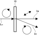
- FIG. 1 shows a conceptual diagram for explaining the polarizing diffraction element of the present invention.
- the polarizing diffraction element 10 shown in FIGS. 1 to 6 diffracts the incident circularly polarized light, and diffracts the polarized light in different (opposite) azimuth directions depending on the rotation direction of the incident circularly polarized light.
- the polarizing diffraction element 10 diffracts the incident light in the upper right direction in the figure when the incident light is right-handed circularly polarized light I Rin (FIGS. 1 to 3), and diffracts the incident light in the lower right direction in the figure when the incident light is left-handed circularly polarized light I Lin (FIGS. 4 to 6).
- the diffracted polarized light (first-order diffracted light) is converted to the opposite rotation direction. That is, when the incident light is right-handed circularly polarized light I Rin , the polarized light (first-order diffracted light) diffracted by the polarizing diffraction element 10 is converted to left-handed circularly polarized light I L1 (FIGS. 1 to 3), and when the incident light is left-handed circularly polarized light I Lin , the polarized light (first-order diffracted light) diffracted by the polarizing diffraction element 10 is converted to right-handed circularly polarized light I R1 (FIGS. 4 to 6).
- the polarization diffraction element 10 shown in Fig. 1 is an example in which, when right-handed polarized light with an ellipticity ⁇ in of 0.95 or more is incident, the zeroth-order light transmitted through the polarization diffraction element 10 becomes right-handed polarized light with an ellipticity ⁇ 0 that satisfies the relationship of the above formula (1).
- the zeroth-order light transmitted through the polarization diffraction element 10 becomes right-handed elliptically polarized light I RE0 , and the difference between the ellipticity ⁇ in of the right-handed circularly polarized light I Rin that is the incident light and the ellipticity ⁇ 0 of the right-handed elliptically polarized light I RE0 that is the zeroth-order light is 0.05 or more. That is, the polarization diffraction element 10 is such that the polarization state of the zeroth-order light is different from that of the incident light.
- the polarization diffraction element 10 shown in FIG. 2 is an example in which the zeroth order light transmitted through the polarization diffraction element 10 becomes left-handed polarized light when right-handed polarized light with an ellipticity ⁇ in of 0.95 or more is incident.
- the polarization diffraction element 10 is such that the zeroth order light transmitted through the polarization diffraction element 10 becomes left-handed circularly polarized light I L0 when approximately right-handed circularly polarized light I Rin is incident. That is, the polarization diffraction element 10 is such that the polarization state of the zeroth order light is different from that of the incident light.
- the zeroth order light transmitted through the polarization diffraction element 10 becomes left-handed circularly polarized light I L0 , but this is not limited thereto, and the zeroth order light may become left-handed elliptically polarized light.
- the polarization diffraction element 10 shown in Fig. 3 is an example in which, when right-handed polarized light having an ellipticity ⁇ in of 0.95 or more is incident, the zeroth-order light transmitted through the polarization diffraction element 10 becomes linearly polarized light I S0. That is, when approximately right-handed circularly polarized light I Rin is incident on the polarization diffraction element 10, the zeroth-order light transmitted through the polarization diffraction element 10 becomes linearly polarized light I S0 . In other words, the polarization diffraction element 10 changes the polarization state of the zeroth-order light to a state different from that of the incident light.
- the polarization diffraction element 10 shown in Fig. 4 is an example in which, when left-handed polarized light with an ellipticity ⁇ in of 0.95 or more is incident, the zeroth-order light transmitted through the polarization diffraction element 10 becomes left-handed elliptically polarized light with an ellipticity ⁇ 0 that satisfies the relationship of the above formula (1).
- the zeroth-order light transmitted through the polarization diffraction element 10 becomes left-handed elliptically polarized light I LE0 , and the difference between the ellipticity ⁇ in of the left-handed circularly polarized light I Lin that is the incident light and the ellipticity ⁇ 0 of the left-handed elliptically polarized light I LE0 that is the zeroth-order light is 0.05 or more. That is, the polarization diffraction element 10 is such that the polarization state of the zeroth-order light is different from that of the incident light.
- the polarization diffraction element 10 shown in FIG. 5 is an example in which the zeroth order light transmitted through the polarization diffraction element 10 becomes right-handed polarized light when left-handed polarized light with an ellipticity ⁇ in of 0.95 or more is incident.
- the polarization diffraction element 10 is such that the zeroth order light transmitted through the polarization diffraction element 10 becomes right-handed circularly polarized light I R0 when approximately left-handed circularly polarized light I Lin is incident. That is, the polarization diffraction element 10 is such that the polarization state of the zeroth order light is different from that of the incident light.
- the zeroth order light transmitted through the polarization diffraction element 10 becomes right-handed circularly polarized light I R0 , but this is not limited thereto, and the zeroth order light may become right-handed elliptically polarized light.
- the polarization diffraction element 10 shown in Fig. 6 is an example in which, when left-handed polarized light having an ellipticity ⁇ in of 0.95 or more is incident, the zeroth-order light transmitted through the polarization diffraction element 10 becomes linearly polarized light I S0. That is, when approximately left-handed circularly polarized light I Lin is incident on the polarization diffraction element 10, the zeroth-order light transmitted through the polarization diffraction element 10 becomes linearly polarized light I S0 . In other words, the polarization diffraction element 10 changes the polarization state of the zeroth-order light to a state different from that of the incident light.
- the polarization state of the zeroth order light transmitted through the polarization diffraction element is the same as that of the incident light. That is, as shown in Fig. 8, when right-handed circularly polarized light I Rin is incident on a conventional polarization diffraction element 100, the zeroth order light transmitted through the polarization diffraction element 100 becomes right-handed circularly polarized light I R0 . Also, as shown in Fig. 9, when left-handed circularly polarized light I Lin is incident on a conventional polarization diffraction element 100, the zeroth order light transmitted through the polarization diffraction element 100 becomes left-handed circularly polarized light I L0 .
- the zeroth order light transmitted through the polarizing diffraction element becomes stray light.
- the incident light including the right circularly polarized component (I Rin ) and the left circularly polarized component (I Lin ) is incident on the polarizing diffraction element 100, and one of the circularly polarized lights (left circularly polarized light I L1 in the illustrated example) is used among the circularly polarized lights diffracted by the polarizing diffraction element 100
- the right circularly polarized light I R1 that is not used can be cut using a circular polarizing plate 20 that transmits the left circularly polarized light and blocks the right circularly polarized light, but the zeroth order light that is transmitted without being diffracted by the polarizing diffraction element becomes the left circularly polarized light I L0 ( has a polarization state different from the right circular
- This left-handed circularly polarized light I L0 of the zeroth order light is not diffracted and travels in a different direction from the left-handed circularly polarized light I L1 which is the first-order diffracted light, and therefore becomes stray light, but because the circular polarizer 20 transmits left-handed polarized light, not only the left-handed circularly polarized light I L1 which is the first-order diffracted light, but also the left-handed circularly polarized light I L0 which is the zeroth order light passes through the circular polarizer 20 and cannot be cut out. Therefore, in an optical device using a polarizing diffraction element, there is a risk that this zeroth order light (left-handed circularly polarized light I L0 ) will reach the observer's eye as a ghost.
- the polarization diffraction element 10 of the present invention is such that the polarization state of the zeroth-order light is different from that of the incident light in any of the configurations shown in Figures 1 to 6. Therefore, the amount of polarized light that passes through the polarization diffraction element 10 as zeroth-order light can be reduced by using a circular polarizer or the like. In other words, the polarization diffraction element 10 can reduce components that could become stray light. Therefore, ghosts can be reduced in optical devices that use polarization diffraction elements.
- the zero-order light is right-handed elliptically polarized light, but since elliptically polarized light contains right-handed and left-handed circularly polarized components, when combined with a circular polarizer that transmits right-handed circularly polarized light and blocks left-handed circularly polarized light, this circular polarizer can block the left-handed circularly polarized component contained in the zero-order light, reducing the amount of zero-order light (a component that can become stray light).
- the zero-order light is left-handed circularly polarized light or left-handed elliptically polarized light, so when combined with a circular polarizer that transmits right-handed circularly polarized light and blocks left-handed circularly polarized light, the left-handed circularly polarized component contained in the zero-order light can be blocked by this circular polarizer, and the amount of zero-order light (a component that can become stray light) can be reduced.
- the zero-order light is linearly polarized, but since linearly polarized light contains right-handed and left-handed circularly polarized components, when combined with a circular polarizer that transmits right-handed circularly polarized light and blocks left-handed circularly polarized light, the left-handed circularly polarized component contained in the zero-order light can be blocked by this circular polarizer, and the amount of zero-order light (a component that can become stray light) can be reduced.
- the zero-order light is left-handed elliptically polarized light, but since elliptically polarized light contains right-handed and left-handed circularly polarized components, when combined with a circular polarizer that transmits left-handed circularly polarized light and blocks right-handed circularly polarized light, this circular polarizer can block the right-handed circularly polarized component contained in the zero-order light, reducing the amount of zero-order light (a component that can become stray light).
- the zero-order light is right-handed circularly polarized light or right-handed elliptically polarized light, so when combined with a circular polarizer that transmits left-handed circularly polarized light and blocks right-handed circularly polarized light, the right-handed circularly polarized component contained in the zero-order light can be blocked by this circular polarizer, and the amount of zero-order light (a component that can become stray light) can be reduced.
- the zero-order light is linearly polarized, but since linearly polarized light contains right-handed and left-handed circularly polarized components, when combined with a circular polarizer that transmits left-handed circularly polarized light and blocks right-handed circularly polarized light, the right-handed circularly polarized component contained in the zero-order light can be blocked by this circular polarizer, and the amount of zero-order light (a component that can become stray light) can be reduced.
- the ellipticity refers to the ellipticity of polarized light.
- "Ellipticity” refers to the ratio of the length of the major axis to the length of the minor axis of an ellipse obtained from the trajectory of a light wave (length of minor axis/length of major axis). Therefore, the closer the ellipticity is to 1, the closer it is to circularly polarized light, and the closer it is to 0, the closer it is to linearly polarized light.
- the ellipticity can be measured using a commercially available polarimeter such as a Stokes polarimeter Poxi-spectra from Tokyo Instruments, a Stokes polarimeter PMI-VIS from Meadowlark, or a polarimeter PAX1000VIS from Thorlabs.
- the polarization state of the zeroth order light can also be determined by measurement using a polarization measuring device such as a commercially available Stokes polarimeter. Although the polarization state of the zeroth order light may vary depending on the wavelength, the polarization state for each wavelength can also be measured.
- the diffraction efficiency of at least one of the first-order diffracted lights output from the polarizing diffraction element is preferably 90% or more, more preferably 93% or more, and even more preferably 95% or more.
- the diffraction efficiency of the first-order diffracted light is measured as follows. First, a laser beam having an output central wavelength of 405 nm, 450 nm, 532 nm, 633 nm, or 650 nm is irradiated from a light source and perpendicularly incident on a polarizing diffraction element. Among the emitted beams, the light intensity of the diffracted beam (first-order beam) diffracted in a desired direction from the polarizing diffraction element, the zeroth-order beam emitted in other directions, and the -1st-order beam are measured by a photodetector, and the diffraction efficiency is calculated by the following formula.
- the zeroth-order beam is the beam emitted in the same direction as the incident beam.
- the -1st-order beam is the beam diffracted in the - ⁇ direction when the diffraction angle of the first-order beam with respect to the zeroth-order beam is ⁇ .
- Diffraction efficiency 1st order light/(1st order light + 0th order light + (-1st order light))
- the average value of the diffraction efficiency is calculated from the measured values at wavelengths of 405 nm, 450 nm, 532 nm, 633 nm, and 650 nm.
- the laser light is vertically incident on a circular polarizer corresponding to the wavelength of the laser light to be circularly polarized, and then the light is incident on a polarizing diffraction element for evaluation.
- the polarization state of the zeroth-order light can be changed more significantly from the polarization state of the incident light, thereby making it possible to further reduce the amount of light components that could become stray light.
- the polarization states of the two zero-order lights emitted from the polarizing diffraction element are not in opposite positions on the Poincaré sphere.
- the polarization state of the zero-order light when the incident light is right-handed polarized and the polarization state of the zero-order light when the incident light is left-handed polarized are not orthogonal to each other.
- the polarization state of the zero-order light can be changed more significantly from the polarization state of the incident light, and the amount of zero-order light (a component that can become stray light) can be reduced by the circular polarizer.
- the polarized diffraction element has a region in which, when left-handed circularly polarized light with an ellipticity ⁇ in of 0.95 or more or right-handed circularly polarized light with an ellipticity ⁇ in of 0.95 or more is incident on the polarized diffraction element at different positions within the plane, the polarization state of the zero-order light is in a different deflection state depending on the position of incidence within the plane.
- the polarization state of the zeroth order light transmitted in each region different according to the diffraction angle and the incident angle of light.
- the amount of transmitted zeroth order light may vary depending on the diffraction angle and/or the incident angle of light.
- the ability of the circular polarizer to block the zeroth order light can be improved in the end region where the zeroth order light is likely to be generated.
- the length of one period in which the diffraction angle of light (the length of one period) changes with increasing radial distance from the center, the length of one period is shorter than in the central region, and the ability of the circular polarizer to block zero-order light can be improved in the edge regions where zero-order light is likely to be generated.
- the polarization state of the zero-order light can be changed more significantly relative to the incident light in areas where zero-order light is more likely to be generated, such as when the diffraction angle of light differs for each position within the plane of the polarizing diffraction element, and the amount of zero-order light (a component that can become stray light) can be reduced by the circular polarizer.
- the polarizing diffraction element has a curved surface portion at least partially within its plane.
- a VR Virtual Reality
- the polarizing diffraction element when a polarizing diffraction element is disposed on the emission surface side of a display, the polarizing diffraction element can be configured to have a curved portion on at least a part of the surface, so that the image light emitted from the display can be further expanded, thereby widening the viewing angle.
- chromatic aberration can be made less likely to occur.
- the position of the curved surface portion is not particularly limited, and may be appropriately set depending on the configuration of the device in which the polarizing diffraction element is disposed, etc.
- the polarizing diffraction element when the viewing angle of the display is to be widened, it is preferable to dispose the polarizing diffraction element so that the curved surface portion is included in the front surface of the display (the direction in which the image is emitted).
- the shape of the curved surface portion of the polarizing diffraction element can be various curved shapes such as a convex shape, a concave shape, a free-form surface, etc., depending on the application.
- the radius of curvature of the curved surface portion in this case may also be appropriately set depending on the application.
- the radius of curvature of the curved surface portion can be in the range of 20 mm to 5000 mm.
- polarizing diffraction elements in which, when right-handed polarized light with an ellipticity ⁇ in of 0.95 or more is incident, the zeroth-order light transmitted through the polarizing diffraction element becomes left-handed polarized light, linearly polarized light, or right-handed polarized light with an ellipticity ⁇ 0 that satisfies the relationship in formula (1) above, or, when left-handed polarized light with an ellipticity ⁇ in of 0.95 or more is incident, the zeroth-order light transmitted through the polarizing diffraction element becomes right-handed polarized light, linearly polarized light, or left-handed polarized light with an ellipticity ⁇ 0 that satisfies the relationship in formula (1) above.
- the polarizing diffraction element of the present invention is preferably a liquid crystal diffraction element having an optically anisotropic layer formed using a liquid crystal composition containing a liquid crystal compound, the optically anisotropic layer having a liquid crystal orientation pattern in which the direction of the optical axis derived from the liquid crystal compound changes while rotating continuously along at least one direction in the plane.
- the polarizing diffraction element of the present invention is also referred to as a liquid crystal diffraction element.
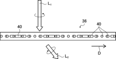
- FIG. 10 conceptually shows an example of the liquid crystal diffraction element of the present invention.
- the liquid crystal diffraction element 10 shown in FIG. 10 has a support 30, an alignment film 32, and an optically anisotropic layer .
- FIG. 11 conceptually shows a plan view of the optically anisotropic layer 36 .
- the plan view is a view of the optically anisotropic layer 36 from a direction perpendicular to the main surface.
- the main surface is the maximum surface of the sheet-like material (film, layer, plate-like material, layer), and is usually both sides in the thickness direction of the sheet-like material.
- the optically anisotropic layer 36 has a structure in which the liquid crystal compound 40 is stacked in the thickness direction, starting from the liquid crystal compound 40 on the surface of the alignment film 32, as shown in FIG.
- the optically anisotropic layer 36 has a liquid crystal alignment pattern in which the direction of an optical axis 40A derived from the liquid crystal compound 40 changes while continuously rotating along the direction of the alignment axis D (the direction of the arrow X described later) within the plane of the optically anisotropic layer 36.
- a rod-shaped liquid crystal compound is exemplified as the liquid crystal compound 40, so that the optical axis coincides with the longitudinal direction of the rod-shaped liquid crystal compound.
- the "optical axis originating from the liquid crystal compound” will also be simply referred to as the "optical axis of the liquid crystal compound”.
- the orientation of the optical axis 40A changes while continuously rotating in the direction of the arrangement axis D (one direction), specifically means that the angle between the optical axis 40A of the liquid crystal compound 40 aligned along the arrangement axis D and the arrangement axis D direction differs depending on the position in the arrangement axis D direction, and the angle between the optical axis 40A and the arrangement axis D direction changes sequentially from ⁇ to ⁇ +180° or ⁇ -180° along the arrangement axis D direction.
- the liquid crystal compounds 40 forming the optically anisotropic layer 36 are arranged at equal intervals in the Y direction perpendicular to the direction of the alignment axis D, i.e., in the Y direction perpendicular to the direction in which the optical axis 40A continuously rotates, with the liquid crystal compounds 40 having the same orientation of the optical axis 40A being aligned.
- the angles between the optical axes 40A and the alignment axis D of the liquid crystal compounds 40 aligned in the Y direction are equal to each other.
- the length (distance) of the optical axis 40A rotating 180° in one direction (the direction of the array axis D in the illustrated example) in which the orientation of the optical axis 40A rotates continuously in the plane in the liquid crystal orientation pattern of the liquid crystal compound 40 is defined as the length ⁇ of one period in the liquid crystal orientation pattern.
- the length of one period in the liquid crystal orientation pattern is defined as the distance from when the angle between the optical axis 40A and the array axis D direction becomes from ⁇ to ⁇ +180°.
- the length of one period in the liquid crystal orientation pattern is the length of one period in the periodic structure of the diffraction element.
- the length ⁇ of one period is defined as the distance between the centers in the direction of the alignment axis D of two liquid crystal compounds 40 that are at the same angle with respect to the direction of the alignment axis D. Specifically, as shown in Fig. 11, the length ⁇ of one period is defined as the distance between the centers in the direction of the alignment axis D of two liquid crystal compounds 40 whose directions of the alignment axis D and the optical axis 40A coincide with each other. In the following description, this length ⁇ of one period is also referred to as "one period ⁇ ".
- the liquid crystal orientation pattern of the optically anisotropic layer repeats this one period ⁇ in the direction of the arrangement axis D, that is, in one direction in which the direction of the optical axis 40A changes by continuously rotating.
- the liquid crystal compounds aligned in the Y direction have an equal angle between their optical axes 40A and the direction of the alignment axis D, which is one direction in which the orientation of the optical axes of the liquid crystal compounds 40 rotates.
- a region R is defined as a region in which the liquid crystal compounds 40, in which the optical axes 40A and the direction of the alignment axis D form an equal angle, are arranged in the Y direction.
- the value of the in-plane retardation (Re) in each region R is preferably half the wavelength, i.e., ⁇ /2.
- the refractive index difference associated with the refractive index anisotropy of the region R in the optically anisotropic layer is a refractive index difference defined by the difference between the refractive index in the direction of the slow axis in the plane of the region R and the refractive index in the direction perpendicular to the direction of the slow axis.
- the refractive index difference ⁇ n associated with the refractive index anisotropy of the region R is equal to the difference between the refractive index of the liquid crystal compound 40 in the direction of the optical axis 40A and the refractive index of the liquid crystal compound 40 in the direction perpendicular to the optical axis 40A in the plane of the region R. That is, the refractive index difference ⁇ n is equal to the refractive index difference of the liquid crystal compound.
- optically anisotropic layer 36 liquid crystal diffraction element
- the light is diffracted (refracted) and the direction of rotation of the circularly polarized light is changed.
- This action is conceptually shown in Figures 12 and 13.
- Figures 12 and 13 in order to simplify the drawings and clearly show the configuration of the liquid crystal diffraction element, only the liquid crystal compound 40 (liquid crystal compound molecules) on the surface of the alignment film of the optically anisotropic layer 36 is shown.
- the optically anisotropic layer 36 has a product of the refractive index difference of the liquid crystal compound and the thickness of the optically anisotropic layer of ⁇ /2.
- the incident light L1 which is left-handed circularly polarized
- the transmitted light L2 which is right-handed circularly polarized and inclined at a certain angle in the direction of the alignment axis D with respect to the incident direction.
- the transmitted light L5 travels in a direction different from that of the transmitted light L2 , that is, in a direction opposite to the array axis D with respect to the incident direction.
- the incident light L4 is converted into the transmitted light L5 of left-handed circular polarization inclined at a certain angle in a direction opposite to the array axis D with respect to the incident direction.
- the optically anisotropic layer 36 has the following characteristics:
- the average period of 10 periods centered on the arbitrary position is calculated along one direction in which the optical axis 40A continuously rotates, i.e., along the direction of the array axis D, and this is defined as the average period ⁇ a.
- the one direction in which the optical axis 40A continuously rotates is also simply referred to as "one direction in which the optical axis 40A rotates.”
- a region having one period equal to or less than this average period ⁇ a is arbitrarily selected, and in this region, the main surface of the optically anisotropic layer 36 (liquid crystal diffraction element 10) is observed under crossed Nicols by an optical microscope.
- the liquid crystal diffraction element 10 is arranged between polarizers arranged in crossed Nicols, and the main surface of the optically anisotropic layer 36 is observed by an optical microscope in the arbitrarily selected region as described above.
- the optically anisotropic layer 36 is arranged so that the absorption axis of one polarizer of the polarizers constituting the crossed Nicols is parallel to the direction of the arrangement axis D, i.e., one direction in which the optical axis 40A rotates, and the observation is performed by the optical microscope.
- the optical axes 40A of the liquid crystal compounds 40 are continuously rotated toward the direction of the alignment axis D. Moreover, the optical axes of the liquid crystal compounds 40 are aligned in the Y direction perpendicular to the direction of the alignment axis D (X direction). Therefore, in a region where the optical axis 40A coincides with the absorption axis of the polarizers constituting the crossed Nicols and in a region where the angle between the optical axis 40A and the absorption axis is small, light is blocked and a dark line extending in the Y direction is observed.
- the "region in which the optical axis 40A coincides with the absorption axis of the polarizer that constitutes the crossed Nicol configuration, and the region in which the angle between the optical axis 40A and the absorption axis is small” will also be referred to for convenience as the "region in which the optical axis 40A (approximately) coincides with the absorption axis of the polarizer.”
- the "region in which the optical axis 40A is perpendicular to the absorption axis of the polarizer that constitutes the crossed Nicol, and the region in which the optical axis 40A has an angle close to perpendicular” is also referred to as the "region in which the optical axis 40A is (almost) perpendicular to the absorption axis of the polarizer.”
- a dark line that is wider than the dark lines on either side is arbitrarily selected with the direction of the absorption axis of the polarizer parallel to the array axis D as the observation direction.
- a dark line sandwiched between dark lines narrower than itself in the array axis D direction is arbitrarily selected.
- the dark line arbitrarily selected in this manner is the first dark line, 20 dark lines consecutive in the observation direction, that is, the direction of the arrangement axis D (one direction), that is, the direction of the absorption axis of the polarizer, are selected.
- the width of the even-numbered dark lines e is narrower than the width of the adjacent odd-numbered dark lines o
- the width of the odd-numbered dark lines o is wider than the width of the adjacent even-numbered dark lines e. That is, the main surface of the optically anisotropic layer 36 constituting the liquid crystal diffraction element of the present invention is observed under a crossed Nicol arrangement in which the direction of the arrangement axis D, i.e., one direction in which the optical axis 40A rotates continuously, coincides with the direction of the absorption axis of one polarizer.
- the liquid crystal diffraction element of the present invention has such an optically anisotropic layer 36, and can convert the polarized light of the zeroth order light transmitted without being diffracted by the liquid crystal diffraction element 10 (optically anisotropic layer 36) into a polarized light different from the incident light. That is, the optically anisotropic layer 36 of the liquid crystal diffraction element is configured such that the width of the dark line is thicker than the adjacent one ⁇ thinner than the adjacent one ⁇ thicker than the adjacent one ⁇ thinner than the adjacent one ...
- the zeroth order light transmitted through the liquid crystal diffraction element becomes left-handed polarized light, linearly polarized light, or right-handed polarized light with an ellipticity ⁇ 0 that satisfies the relationship of the above formula (1), or when a left-handed polarized light with an ellipticity ⁇ in of 0.95 or more is incident, the zeroth order light transmitted through the liquid crystal diffraction element becomes right-handed polarized light, linearly polarized light, or left-handed polarized light with an ellipticity ⁇ 0 that satisfies the relationship of the above formula (1).
- an optically anisotropic layer having a liquid crystal orientation pattern in which the optical axis of the liquid crystal compound rotates continuously in one direction has a constant rotation of the optical axis 40A over one period ⁇ toward the direction of the alignment axis D, as in the optically anisotropic layer 36Z conceptually shown in Figure 22.
- the rotation angle of the optical axis 40A is approximately constant during one period ⁇ in which the optical axis 40A changes from a state parallel to the arrangement axis D to a state perpendicular to the arrangement axis D and then returns to a state parallel to the arrangement axis D.
- the rotation of the optical axis 40A during one period ⁇ is a linear rotation with a constant rotation angle.
- such a liquid crystal alignment pattern in which the rotation of the optical axis 40A in one period ⁇ is constant is also referred to as a "linear liquid crystal alignment pattern" for convenience.
- the liquid crystal orientation pattern is linear, the thickness of the dark lines aligned in the direction of the alignment axis D is approximately constant.
- a conventional liquid crystal diffraction element having an optically anisotropic layer 36Z in which the liquid crystal orientation pattern is linear it is known that the polarization state of the zero-order light that passes straight through the liquid crystal diffraction element (optically anisotropic layer) without being diffracted is the same as that of the incident light. That is, as conceptually shown in FIG. 9, in a conventional optically anisotropic layer 36Z having a linear liquid crystal orientation pattern, when the incident light is right-handed circularly polarized light, the zero-order light is also right-handed circularly polarized light as it is.
- the rotation of the optic axis 40A per period ⁇ is not constant.
- the optical axis 40A rotates from a state parallel to the arrangement axis D to an angle close to perpendicular to the arrangement axis D at a large rotation angle, then rotates at a small rotation angle to a state perpendicular to the arrangement axis D, and after rotating at a small rotation angle, the rotation angle increases and the optical axis 40A becomes parallel to the arrangement axis D again.
- the rotation angle of the optical axis 40A in one period ⁇ becomes small from a large state, and then becomes large again.
- the rotation of the optical axis 40A in one period ⁇ is a nonlinear rotation in which the rotation angle changes.
- such a liquid crystal alignment pattern in which the rotation of the optical axis 40A per period ⁇ is not constant is also referred to as a "nonlinear liquid crystal alignment pattern" for convenience.
- the optical axis 40A coincides with the absorption axis of the polarizer
- the light is blocked and a dark line extending in the Y direction is observed.
- the width in the direction of the alignment axis D of the region where the optical axis 40A and the absorption axis of the polarizer arranged in crossed Nicols (approximately) coincide with each other changes in one period.
- the width in the direction of the alignment axis D of the region where the absorption axis in the direction of the alignment axis D (approximately) coincides with the absorption axis in the Y direction perpendicular to the direction of the alignment axis D is narrow, and the width in the direction of the alignment axis D of the region where the absorption axis in the Y direction (approximately) coincides with the absorption axis in the Y direction perpendicular to the direction of the alignment axis D is wide.
- an optically anisotropic layer 36 in which the width of the even-numbered dark lines e is narrower than the width of the adjacent odd-numbered dark lines o and the width of the odd-numbered dark lines o is wider than the width of the adjacent even-numbered dark lines e among 20 consecutive dark lines selected as described above has a nonlinear liquid crystal orientation pattern in which the rotation of the optical axis 40A in one period is not constant.
- an optically anisotropic layer in which thick and thin dark lines are observed alternately in the direction of the alignment axis D has a nonlinear liquid crystal orientation pattern in which the rotation of the optical axis 40A facing the direction of the alignment axis D is not constant.
- the liquid crystal diffraction element of the present invention can convert the polarization state of the zero-order light in the optically anisotropic layer into a polarization state different from that of the incident light by virtue of the optically anisotropic layer having a nonlinear liquid crystal orientation pattern. That is, as conceptually shown in each of Figures 1 to 6, the optically anisotropic layer 36 having a nonlinear liquid crystal orientation pattern used in the present invention can convert the polarization state of the zero-order light of the optically anisotropic layer into a polarization state different from that of the incident light. For example, as shown in the example of Figure 1, when the incident light is right-handed circularly polarized light, the optically anisotropic layer 36 can convert the zero-order light into elliptically polarized light with a right-handed rotation direction.
- the zero-order light can be converted into a polarized light different from that of the incident light, making it possible to remove the zero-order light, for example, in image display applications where the zero-order light becomes stray light as described above.
- the optically anisotropic layer 36 has a large difference in width between the wide dark lines, i.e., the odd-numbered dark lines o, and the narrow dark lines, i.e., the even-numbered dark lines e.
- the difference in thickness between the wide dark lines and between the narrow dark lines in the optically anisotropic layer 36 is small. The smaller this difference is, the more preferable it is in terms of preventing diffracted light from becoming stray light.
- the optically anisotropic layer 36 preferably has 20 consecutive dark lines selected as described above that satisfy the following formula: [Average odd-numbered dark line width] - [Average even-numbered dark line width] > ([Standard deviation of odd-numbered dark line widths] + [Standard deviation of even-numbered dark line widths]) / 2
- the optically anisotropic layer 36 satisfies this formula, the above-mentioned effects can be more suitably exhibited.
- the optically anisotropic layer 36 can adjust the angles of diffraction (refraction) of the transmitted light L2 and L5 by changing one period ⁇ of the liquid crystal orientation pattern formed. Specifically, the shorter one period ⁇ of the liquid crystal orientation pattern of the optically anisotropic layer 36, the stronger the interference between the lights that have passed through the adjacent liquid crystal compounds 40, and therefore the greater the diffraction of the transmitted light L2 and L5 . Therefore, when the optically anisotropic layer 36 has regions in its plane where the length of one period ⁇ is different, it is possible to diffract incident light in different directions.
- the optically anisotropic layer 36 may have a region in which the length of one period in the plane gradually changes in one direction in which the liquid crystal compound rotates, in the illustrated example, the direction of the array axis D.
- a liquid crystal diffraction element that focuses or diverges diffracted light primary light
- a liquid crystal diffraction element that focuses (or diverges) diffracted light at the center in the array axis D direction can be obtained.
- the direction of diffraction of the transmitted light can be reversed. That is, in the example shown in Figures 12 and 13, the direction of rotation of the optical axis 40A facing the direction of the array axis D is clockwise, but by changing this rotation direction to counterclockwise, the direction of diffraction of the transmitted light can be reversed.
- the angle of diffraction (refractive angle) by the optically anisotropic layer 36 varies depending on the wavelength of the incident light. Specifically, the longer the wavelength of light, the greater the diffraction intensity. In other words, among red, green, and blue light, the red light is diffracted most, the green light is diffracted next, and the blue light is diffracted least.
- the angle of diffraction changes depending on one period ⁇ in the liquid crystal orientation pattern of the optically anisotropic layer 36. Therefore, by making one period ⁇ in the liquid crystal orientation pattern of the optically anisotropic layer 36 uniform, light of the same wavelength can be diffracted at the same angle.
- the in-plane retardation value of the multiple regions R is preferably a half wavelength
- the in-plane retardation Re(550) ⁇ n550 ⁇ d of the multiple regions R of the optically anisotropic layer 36 satisfies formula (1), a sufficient amount of the circularly polarized component of light incident on the optically anisotropic layer 36 can be converted into circularly polarized light traveling in a direction tilted forward or backward with respect to the direction of the alignment axis D.
- the in-plane retardation values of the multiple regions R in the optically anisotropic layer 36 can be outside the range of the above formula (1).
- ⁇ n 550 ⁇ d ⁇ 200 nm or 350 nm ⁇ n 550 ⁇ d
- light can be separated into light traveling in the same direction as the incident light and light traveling in a direction different from the incident light.
- ⁇ n 550 ⁇ d approaches 0 nm or 550 nm, the component of light traveling in the same direction as the incident light increases, and the component of light traveling in a direction different from the incident light decreases.
- the formula (2) indicates that the liquid crystal compound 40 contained in the optically anisotropic layer 36 has reverse dispersion. That is, when the formula (2) is satisfied, the optically anisotropic layer 36 can accommodate incident light in a wide band of wavelengths.
- the optically anisotropic layer 36 has the optical axis 40A of the liquid crystal compound 40 continuously rotated in one direction, that is, toward the direction of the alignment axis D.
- the present invention is not limited to this, and in the optically anisotropic layer of the liquid crystal diffraction element of the present invention, the direction in which the optical axis 40A continuously rotates can be in various modes, such as two perpendicular directions.
- FIG. 15 conceptually shows one example of this.
- the optically anisotropic layer 36S shown in Figure 15 has a concentric liquid crystal orientation pattern in which the direction of the optical axis of the liquid crystal compound 40 changes while continuously rotating in one direction (arrows A1 to A3 , etc.) radially from the inside to the outside.
- a concentric pattern is a pattern in which the lines connecting the liquid crystal compounds whose optical axes are oriented in the same direction are circular, and the segments of the circle are concentric.
- each direction radially outward from the center of the optically anisotropic layer 36S corresponds to the alignment axis D direction in the optically anisotropic layer 36 described above.
- the optically anisotropic layer 36S shown in Fig. 15 has a concentric liquid crystal orientation pattern. Therefore, in this example, when the optically anisotropic layer 36S (liquid crystal diffraction element) is observed under crossed Nicols with an optical microscope, for example, with the direction of the arrow A2 in the figure as the absorption axis of one polarizer, dark and bright lines are observed alternately in a concentric pattern. 15, the 80 dark lines selected in the same manner as in the above example are narrower than the adjacent odd-numbered dark lines, and wider than the adjacent even-numbered dark lines. Therefore, in this example, as conceptually shown in FIG. 15, dark lines narrower than the adjacent dark lines and dark lines wider than the adjacent dark lines are alternately observed in a concentric pattern.
- the liquid crystal alignment pattern facing one direction is depicted as a linear liquid crystal alignment pattern.
- the liquid crystal orientation pattern is nonlinear as described above. Therefore, in this example as well, the polarization state of the zero-order light is converted to a state different from that of the incident light.
- the optical axis (not shown) of the liquid crystal compound 40 is also in the longitudinal direction of the liquid crystal compound 40.
- the direction of the optical axis of the liquid crystal compound 40 changes while continuously rotating along a number of directions from the center of the optically anisotropic layer 36 toward the outside, for example, the direction indicated by the arrow A1 , the direction indicated by the arrow A2 , the direction indicated by the arrow A3 , ....
- the arrows A1 , A2 , and A3 are alignment axes similar to the alignment axis D described above.
- the same concentric circle on which the optical axes of the liquid crystal compounds 40 are oriented in the same direction corresponds to the Y direction of the optically anisotropic layer 36 described above. 15 also diffracts the incident light to the directions of arrows A1 , A2 , A3 , etc., due to the same effect. Also, as in the previous example, the zero-order light is converted into a polarized light different from that of the incident light.
- the optically anisotropic layer 36S of the liquid crystal diffraction element has regions in which one period ⁇ of the liquid crystal orientation pattern varies within the plane. Specifically, in the direction along the arrow A1 in Fig. 15, for example, one period ⁇ is gradually shortened from the center toward the outside in the direction in which the direction of the optical axis of the liquid crystal compound 40 changes while continuously rotating. That is, in Fig. 15, one period near the outside is shorter than one period near the center.
- the gradual change of one period ⁇ means that one period ⁇ changes continuously and that one period ⁇ changes stepwise. This also applies to the above-mentioned examples.
- the diffraction angle of the liquid crystal diffraction element depends on one period ⁇ of the liquid crystal orientation pattern, and the smaller the period ⁇ , the larger the diffraction angle. Therefore, in this example, the optically anisotropic layer 36S diffracts the incident light toward the center. That is, the liquid crystal diffractive element having the optically anisotropic layer 36S can transmit the incident light as a convergent light, and exhibits a function as, for example, a convex lens.
- the optically anisotropic layer 36 is formed using a liquid crystal composition containing a liquid crystal compound, and has a liquid crystal orientation pattern in which the direction of the optical axis of the liquid crystal compound changes continuously toward at least one direction in the plane.
- the liquid crystal compounds 40 are oriented in the same direction in the thickness direction.
- the present invention is not limited to this, and liquid crystal compound 40 may be aligned in a helical twist in the thickness direction as in an optically anisotropic layer 36A conceptually shown in FIG.
- An optically anisotropic layer having a liquid crystal orientation pattern as described above has bright areas 42 and dark areas 44 extending from one surface to the other surface in a cross-sectional image observed with a scanning electron microscope (SEM) at a cross-section cut in the thickness direction along the direction in which the optical axis rotates continuously.
- SEM scanning electron microscope
- Such an image of a cross section of an optically anisotropic layer observed with an SEM is also referred to as a "cross-sectional SEM image" for convenience.
- the bright areas 42 and dark areas 44 observed in the cross-sectional SEM image are due to a liquid crystal phase having a liquid crystal orientation pattern.
- optically anisotropic layer 36 shown in Figures 10 and 11, in which the liquid crystal compound 40 is not helically twisted in the thickness direction, has, in a cross-sectional SEM image, light areas 42 and dark areas 44 extending from one surface to the other surface in the thickness direction, i.e., perpendicular to the main surface.
- an optically anisotropic layer 36A in which liquid crystal compound 40 is helically oriented in the thickness direction has, in a cross-sectional SEM image, bright areas 42 and dark areas 44 that are inclined with respect to the thickness direction, i.e., the main surface, of the optically anisotropic layer 36A and extend from one surface to the other, as conceptually shown in Figure 17.
- the effective birefringence of the liquid crystal compound increases when light is diffracted, and the diffraction efficiency can be increased. Furthermore, the change in the zeroth order light relative to the incident light can be made larger.
- the difference between the diffraction efficiency of the first order diffracted light emitted from the liquid crystal diffraction element when right-handed polarized light with an ellipticity ⁇ in of 0.95 or more is incident on the liquid crystal diffraction element, and the diffraction efficiency of the first order diffracted light emitted from the liquid crystal diffraction element when left-handed polarized light with an ellipticity ⁇ in of 0.95 or more is incident on the liquid crystal diffraction element can be made larger.
- the ratio DE(1S)/DE(1L) between the diffraction efficiency DE(1L) of the first order diffracted light with high diffraction efficiency and the diffraction efficiency DE(1S) of the first order diffracted light with low diffraction efficiency can be made 0.95 or less.
- the angle of the dark area 44 (light area 42) relative to the main surface in a cross-sectional SEM image can be adjusted by the length of one period in the above-mentioned liquid crystal orientation pattern and the magnitude of twist of the liquid crystal compound 40 twisted and oriented in the thickness direction. Specifically, the shorter one period in the liquid crystal alignment pattern, the larger the angle of the dark portion 44 with respect to the main surface. Also, the smaller the twist in the thickness direction, the larger the angle of the dark portion 44 with respect to the main surface.
- the helical twisted alignment of the liquid crystal compound in the optically anisotropic layer can be achieved by adding a chiral agent to the liquid crystal composition for forming the optically anisotropic layer, which will be described later.
- a chiral agent By selecting and adjusting the type and amount of the chiral agent, the twist direction and degree of twist of the liquid crystal compound 40 can be adjusted.
- the optically anisotropic layer is not limited to having light areas 42 and dark areas 44 in a linear shape as shown in FIG.
- a region in which the liquid crystal compound 40 is helically twisted in the thickness direction is sandwiched between regions in which the liquid crystal compound is not helically twisted and oriented, so that a region having light portions 42 and dark portions 44 extending in the thickness direction is sandwiched between regions in which the inclination directions of the light portions 42 and dark portions 44 are opposite.
- the liquid crystal compound 40 has its optical axis 40A aligned parallel to the principal surface (XY surface) in the XZ plane of the optically anisotropic layer 36.
- the present invention is not limited to this.
- the optical axis 40A of the liquid crystal compound 40 may be aligned in a tilted manner with respect to the main surface (XY plane).
- the inclination angle (tilt angle) of the optical axis 40A of the liquid crystal compound 40 with respect to the main surface (XY plane) in the X-Z plane of the optically anisotropic layer 36C is uniform in the thickness direction (Z direction), but the present invention is not limited to this. That is, the optically anisotropic layer 36C may have a region in which the tilt angle of the optical axis 40A varies in the thickness direction.
- the liquid crystal compound 40 may be oriented so that the optical axis 40A of the optically anisotropic layer 36C is parallel to the main surface (tilt angle 0°) at the interface on the alignment film 32 side, and the tilt angle of the optical axis 40A increases as it moves away from the interface on the alignment film 32 side in the thickness direction, and then the tilt angle of the optical axis 40A remains constant up to the other interface (air interface).
- the optical axis 40A of the liquid crystal compound 40 may have a tilt angle at one of the upper and lower interfaces, or may have tilt angles at both interfaces. Also, the tilt angles at both interfaces may be different. Since the optical axis 40A of the liquid crystal compound 40 has a tilt angle (is inclined) in this manner, the effective birefringence of the liquid crystal compound becomes high when light is diffracted, thereby improving the diffraction efficiency and further increasing the change in the zero-order light relative to the incident light.
- the optically anisotropic layer of the liquid crystal diffraction element of the present invention may have only one or both of the following configurations: a configuration having dark areas 44 inclined with respect to the main surface (thickness direction) in a cross-sectional SEM image, and a configuration in which the optical axis 40A of the liquid crystal compound 40 is tilted.
- a preferred example is a configuration in which the average tilt angle of dark areas 44 in a cross-sectional SEM image is 5° or more relative to the main surface of the optically anisotropic layer, and the tilt angle of the optical axis 40A of the liquid crystal compound 40 in the thickness direction is less than 5°.
- Another preferred example is a configuration in which the average tilt angle of the dark areas 44 in a cross-sectional SEM image is less than 5° with respect to the main surface of the optically anisotropic layer, and the tilt angle of the optical axis 40A of the liquid crystal compound 40 in the thickness direction is 5° or more.
- a preferred example of a configuration is one in which the average inclination angle of the dark areas 44 in a cross-sectional SEM image is 5° or more relative to the main surface of the optically anisotropic layer, and the tilt angle of the optical axis 40A of the liquid crystal compound 40 in the thickness direction is 5° or more.
- the liquid crystal diffraction element of the present invention having such an optically anisotropic layer, can increase the change in the polarization state of the zero-order light relative to the incident light, and as a result, can more effectively suppress stray light when the zero-order light becomes stray light, and can more effectively improve the light utilization rate.
- the liquid crystal diffraction element 10 shown in Figures 10 and 11 has a support 30, an alignment film 32, and an optically anisotropic layer 36.
- the liquid crystal diffraction element of the present invention is not limited to the example shown in FIG. 10, and various layer configurations can be used.
- the liquid crystal diffraction element of the present invention may be one in which the support 30 is peeled off from the liquid crystal diffraction element shown in FIG. 10 and the alignment film 32 and the optically anisotropic layer 36 are formed.
- the liquid crystal diffraction element of the present invention may be one in which the support 30 and the alignment film 32 are peeled off from the liquid crystal diffraction element shown in FIG. 10 and the optically anisotropic layer 36 are formed.
- the liquid crystal diffraction element of the present invention may be one in which the support 30 and the optically anisotropic layer 36 are formed.
- the liquid crystal diffraction element of the present invention may have other layers such as a protective layer (hard coat layer) and an anti-reflection layer. That is, the liquid crystal diffraction element of the present invention can have various layer configurations as long as it has an optically anisotropic layer, which will be described later.
- the support 30 supports the alignment film 32 and the optically anisotropic layer 36 .
- the support 30 may be any sheet-like material (film, plate-like material) as long as it can support the alignment film and the optically anisotropic layer.
- the support 30 is preferably a transparent support, and examples of such support include polyacrylic resin films such as polymethyl methacrylate, cellulose resin films such as cellulose triacetate, cycloolefin polymer films (for example, trade name "Arton” manufactured by JSR Corporation, trade name "ZEONOR” manufactured by Zeon Corporation), polyethylene terephthalate (PET), polycarbonate, and polyvinyl chloride.
- the support is not limited to a flexible film, and may be a non-flexible substrate such as a glass substrate.
- the support 30 may be multi-layered. Examples of multi-layered support include a support that includes any of the above-mentioned supports as a substrate, and another layer is provided on the surface of the substrate.
- the thickness of the support 30 is preferably from 1 to 1000 ⁇ m, more preferably from 3 to 250 ⁇ m, and even more preferably from 5 to 150 ⁇ m.
- the alignment film 32 is formed on the surface of the support 30 .
- the alignment film 32 is an alignment film for aligning the liquid crystal compound 40 in the above-mentioned predetermined liquid crystal alignment pattern when the optically anisotropic layer 36 is formed.
- the optically anisotropic layer has a liquid crystal orientation pattern in which the direction of the optical axis 40A (see FIG. 11) of the liquid crystal compound 40 changes while continuously rotating along one in-plane direction (the direction of the arrow X described later). Therefore, the alignment film is formed so that the optically anisotropic layer can form this liquid crystal orientation pattern.
- the length over which the orientation of the optical axis 40A rotates 180° is defined as one period ⁇ (rotation period of the optical axis).
- the alignment film various known films can be used. Examples of such films include a rubbed film made of an organic compound such as a polymer, an obliquely evaporated film of an inorganic compound, a film having a microgroove, and a film obtained by accumulating LB (Langmuir-Blodgett) films made by the Langmuir-Blodgett method of an organic compound such as ⁇ -tricosanoic acid, dioctadecylmethylammonium chloride, and methyl stearate.
- LB Lightmuir-Blodgett
- the alignment film formed by rubbing treatment can be formed by rubbing the surface of the polymer layer several times in a certain direction with paper or cloth.
- Preferred examples of materials used for the alignment film include polyimide, polyvinyl alcohol, polymerizable group-containing polymers described in JP-A-9-152509, and materials used to form alignment films described in JP-A-2005-97377, JP-A-2005-99228, and JP-A-2005-128503.
- the alignment film is preferably a so-called photo-alignment film, which is formed by irradiating a photo-alignment material with polarized or non-polarized light. That is, in the liquid crystal diffraction element of the present invention, the alignment film is preferably a photo-alignment film formed by applying a photo-alignment material onto the support 30.
- the photo-alignment film can be irradiated with polarized light from a vertical direction or an oblique direction, while the photo-alignment film can be irradiated with unpolarized light from an oblique direction.
- photo-alignment materials used in the photo-alignment film examples include those described in JP-A-2006-285197, JP-A-2007-76839, JP-A-2007-138138, JP-A-2007-94071, JP-A-2007-121721, JP-A-2007-140465, JP-A-2007-156439, and JP-A-2007-160144.
- photocrosslinkable polyimides photocrosslinkable polyamides and photocrosslinkable esters described in JP-T-2003-520878, JP-T-2004-529220 and JP-T-4162850, and photodimerizable compounds described in JP-A-9-118717, JP-T-10-506420, JP-T-2003-505561, WO 2010/150748, JP-A-2013-177561 and JP-A-2014-12823, in particular cinnamate compounds, chalcone compounds and coumarin compounds, are exemplified as preferred examples.
- azo compounds photocrosslinkable polyimides, photocrosslinkable polyamides, photocrosslinkable esters, cinnamate compounds, and chalcone compounds are preferably used.
- the thickness of the alignment film is preferably from 0.01 to 5 ⁇ m, and more preferably from 0.05 to 2 ⁇ m.
- the method for forming the alignment film there are no limitations on the method for forming the alignment film, and various known methods can be used depending on the material for forming the alignment film.
- One example is a method in which an alignment film is applied to the surface of the support 30, dried, and then exposed to laser light to form an alignment pattern.
- Figure 20 conceptually shows an example of an exposure device that exposes an alignment film to form an alignment pattern that corresponds to a liquid crystal alignment pattern in which the optical axis 40A of the liquid crystal compound 40 rotates continuously in one direction, i.e., the direction of the alignment axis D, shown in Figure 11.
- the exposure device 60 shown in Figure 20 includes a light source 64 equipped with a laser 62, a ⁇ /2 plate 65 that changes the polarization direction of the laser light M emitted by the laser 62, a beam splitter 68 that splits the laser light M emitted from the laser 62 into two light beams MA and MB, mirrors 70A and 70B that are respectively arranged on the optical paths of the two split light beams MA and MB, and ⁇ /4 plates 72A and 72B.
- the light source 64 emits linearly polarized light P 0.
- the ⁇ /4 plate 72A converts the linearly polarized light P 0 (light beam MA) into right-handed circularly polarized light P R
- the ⁇ /4 plate 72B converts the linearly polarized light P 0 (light beam MB) into left-handed circularly polarized light P L.
- a support 30 having an alignment film 32 before an alignment pattern is formed is placed in an exposure section, and two light beams MA and MB are made to intersect and interfere on the alignment film 32, and the alignment film 32 is exposed by being irradiated with the interference light. Due to the interference at this time, the polarization state of the light irradiated to the alignment film 32 changes periodically in the form of interference fringes. As a result, an alignment pattern in which the alignment state changes periodically is obtained in the alignment film 32. That is, an alignment film having an alignment pattern in which the alignment state changes periodically (hereinafter also referred to as a pattern alignment film) is obtained.
- the period of the orientation pattern can be adjusted by changing the crossing angle ⁇ of the two light beams MA and MB.
- the length of one period (one period ⁇ ) in which the optical axis 40A rotates 180° in one direction can be adjusted by adjusting the crossing angle ⁇ .
- an optically anisotropic layer 36 can be formed having a liquid crystal alignment pattern in which the optical axis 40A of the liquid crystal compound 40 rotates continuously in one direction, as described below.
- the rotation direction of the optical axis 40A can be reversed.
- Figure 21 conceptually shows an example of an exposure device that forms an orientation pattern corresponding to the concentric liquid crystal orientation pattern shown in Figure 15.
- the exposure device 80 shown in FIG. 21 has a light source 84 equipped with a laser 82, a polarizing beam splitter 86 that splits the laser light M from the laser 82 into S-polarized light MS and P-polarized light MP, a mirror 90A arranged in the optical path of the P-polarized light MP, a mirror 90B arranged in the optical path of the S-polarized light MS, a lens 92 arranged in the optical path of the S-polarized light MS, a polarizing beam splitter 94, and a ⁇ /4 plate 96.
- the P-polarized light MP split by the polarizing beam splitter 86 is reflected by a mirror 90A and enters a polarizing beam splitter 94.
- the S-polarized light MS split by the polarizing beam splitter 86 is reflected by a mirror 90B, collected by a lens 92, and enters the polarizing beam splitter 94.
- the P-polarized light MP and the S-polarized light MS are combined by the polarizing beam splitter 94 and converted by the ⁇ /4 plate 96 into right-handed circularly polarized light and left-handed circularly polarized light according to the polarization direction, and enter the alignment film 32 on the support 30.
- the interference between the right-handed and left-handed circularly polarized light causes the polarization state of the light irradiated onto the alignment film to periodically change in the form of interference fringes.
- the crossing angle between the left-handed and right-handed circularly polarized light changes from the inside to the outside of the concentric circles, an exposure pattern is obtained whose pitch changes from the inside to the outside. This results in a concentric alignment pattern in which the alignment state periodically changes on the alignment film.
- one period ⁇ of the liquid crystal orientation pattern in which the optical axis of the liquid crystal compound 40 continuously rotates 180° along one direction can be controlled by changing the refractive power of the lens 92 (the F-number of the lens 92), the focal length of the lens 92, and the distance between the lens 92 and the orientation film 32, etc.
- the refractive power of the lens 92 the F-number of the lens 92
- the length ⁇ of one period of the liquid crystal alignment pattern can be changed in one direction in which the optical axis rotates continuously.
- the length ⁇ of one period of the liquid crystal orientation pattern can be changed in one direction in which the optical axis rotates continuously, depending on the spread angle of the light spread by the lens 92 that interferes with the parallel light. More specifically, when the refractive power of the lens 92 is weakened, the light approaches parallel light, so that the length ⁇ of one period of the liquid crystal orientation pattern gradually shortens from the inside to the outside, and the F-number becomes larger. Conversely, when the refractive power of the lens 92 is strengthened, the length ⁇ of one period of the liquid crystal orientation pattern suddenly shortens from the inside to the outside, and the F-number becomes smaller.
- the patterned alignment film has an alignment pattern that aligns the liquid crystal compound 40 so that the direction of the optical axis of the liquid crystal compound in the optically anisotropic layer formed on the patterned alignment film becomes a liquid crystal alignment pattern in which the direction of the optical axis of the liquid crystal compound 40 changes while rotating continuously along at least one direction in the plane.
- the axis along which the patterned alignment film aligns the liquid crystal compound 40 is the alignment axis, it can be said that the patterned alignment film has an alignment pattern in which the direction of the alignment axis changes while rotating continuously along at least one direction in the plane.
- the alignment axis of the patterned alignment film can be detected by measuring the absorption anisotropy. For example, when the patterned alignment film is irradiated with linearly polarized light while rotating and the amount of light transmitted through the patterned alignment film is measured, the direction in which the amount of light is maximum or minimum is observed to change gradually along one direction in the plane.
- the alignment film is provided as a preferred embodiment, but is not an essential component.
- the alignment film is provided as a preferred embodiment, but is not an essential component.
- the optically anisotropic layer 36, etc. to have a liquid crystal orientation pattern in which the orientation of the optical axis 40A of the liquid crystal compound 40 changes while continuously rotating along at least one direction in the plane.
- liquid crystal diffraction element for example when it is desired to provide a light quantity distribution in the transmitted light, it is also possible to use a configuration having regions in the direction of the array axis D where the period ⁇ is partially different, rather than gradually changing the period ⁇ along the direction of the array axis D.
- one method of partially changing the period ⁇ is to use a method of patterning a photo-alignment film by scanning exposure while arbitrarily changing the polarization direction of focused laser light.
- the wavelength of the laser used to expose the alignment film can be set appropriately depending on the type of alignment film used.
- lasers with wavelengths ranging from deep ultraviolet to visible light to infrared can be preferably used.
- lasers with wavelengths of 266 nm, 325 nm, 355 nm, 370 nm, 385 nm, 405 nm, and 460 nm can be used, but are not limited to the above, and lasers with various wavelengths can be used depending on the type of alignment film used.
- the optically anisotropic layer may be peeled off and/or transferred from the alignment film.
- the transfer may be performed multiple times depending on the bonding surface of the optically anisotropic layer.
- the peeling and/or transfer method may be freely selected depending on the purpose. For example, after transferring once to a substrate having an adhesive layer, the substrate may be re-transferred to an object to which the layer is to be transferred, and the substrate may be peeled off, so that the interface of the optically anisotropic layer on the alignment film side becomes the object to which the layer is to be transferred.
- the optically anisotropic layer when the surface of the optically anisotropic layer opposite to the alignment film becomes the object to which the layer is to be transferred, the optically anisotropic layer may be peeled off from the alignment film after bonding the optically anisotropic layer and the object to which the layer is to be transferred via an adhesive.
- peeling the optically anisotropic layer from the alignment film it is preferable to adjust the peeling angle, speed, etc. in order to reduce damage (tears, knicks, etc.) to the optically anisotropic layer and the alignment film.
- the alignment film may be repeatedly used as long as the alignment is not affected.
- the alignment film Before providing the optically anisotropic layer on the alignment film, the alignment film may be washed with an organic solvent or the like.
- optically anisotropic layer 36 On the surface of the alignment film 32, an optically anisotropic layer 36 is formed.
- the optically anisotropic layer is formed by forming an alignment film 32 having the above-mentioned alignment pattern on a support 30, and applying and curing a liquid crystal composition on the alignment film.
- a structure in which the optical axis of the liquid crystal compound in the optically anisotropic layer is helically twisted and oriented in the thickness direction of the optically anisotropic layer i.e., a configuration in which the dark areas 44 are inclined with respect to the main surface (thickness direction), can be formed by adding a chiral agent that helically aligns the liquid crystal compound in the thickness direction to the liquid crystal composition.
- the magnitude of the helical twist alignment of the liquid crystal compound in the thickness direction can be adjusted by the type and amount of the chiral dopant added to the liquid crystal composition.
- the twist direction (right twist/left twist) of the liquid crystal compound in the thickness direction can also be selected by selecting the type of chiral agent added to the liquid crystal composition.
- the present invention also includes an embodiment in which a laminate integrally comprising a support and an alignment film functions as a ⁇ /2 plate.
- the liquid crystal composition for forming the optically anisotropic layer contains a rod-shaped liquid crystal compound or a discotic liquid crystal compound, and may further contain other components such as a leveling agent, an alignment control agent, a polymerization initiator, and an alignment assistant.
- the thickness of the optically anisotropic layer there is no limit to the thickness of the optically anisotropic layer, and the thickness that provides the desired optical characteristics can be set appropriately depending on one period ⁇ of the liquid crystal orientation pattern, the required diffraction angle, the diffraction efficiency, etc.
- Rod-shaped liquid crystal compounds As the rod-shaped liquid crystal compound, azomethines, azoxys, cyanobiphenyls, cyanophenyl esters, benzoates, cyclohexane carboxylic acid phenyl esters, cyanophenylcyclohexanes, cyano-substituted phenylpyrimidines, alkoxy-substituted phenylpyrimidines, phenyldioxanes, tolanes, and alkenylcyclohexylbenzonitriles are preferably used. Not only the above-mentioned low molecular weight liquid crystal molecules, but also polymeric liquid crystal molecules can be used.
- rod-shaped liquid crystal compounds examples include Makromol. Chem. , Vol. 190, p. 2255 (1989), Advanced Materials, Vol. 5, p. 107 (1993), U.S. Patent Nos. 4,683,327, 5,622,648, and 5,770,107, International Publication Nos. 95/22586, 95/24455, 97/00600, 98/23580, and 98/52905, JP-A-1-272551, JP-A-6-16616, JP-A-7-110469, JP-A-11-80081, and Japanese Patent Application No. 2001-64627 can be used.
- rod-shaped liquid crystal compounds those described in, for example, JP-T-11-513019 and JP-A-2007-279688 can also be preferably used.
- the discotic liquid crystal compound for example, those described in JP-A-2007-108732 and JP-A-2010-244038 can be preferably used.
- the liquid crystal compound 40 stands up in the thickness direction in the optically anisotropic layer, and the optical axis 40A derived from the liquid crystal compound 40 is defined as an axis perpendicular to the disc surface, that is, a so-called fast axis.
- liquid crystal compound a liquid crystal compound with a high refractive index difference ⁇ n can be preferably used to obtain high diffraction efficiency. By increasing the refractive index anisotropy, it is possible to maintain high diffraction efficiency when the incident angle changes.
- liquid crystal compound with a high refractive index difference ⁇ n there is no particular limitation, but the compounds exemplified in WO 2019/182129 and the compounds represented by the following general formula (I) can be preferably used.
- P 1 and P 2 each independently represent a hydrogen atom, -CN, -NCS or a polymerizable group.
- Sp 1 and Sp 2 each independently represent a single bond or a divalent linking group, provided that Sp 1 and Sp 2 do not represent a divalent linking group containing at least one group selected from the group consisting of an aromatic hydrocarbon ring group, an aromatic heterocyclic group, and an aliphatic hydrocarbon ring group.
- R represents a hydrogen atom or an alkyl group having 1 to 10 carbon atoms.
- R's When there are a plurality of R's, they may be the same or different.
- Z 1's and Z 2 's they may be the same or different.
- Z 3 's they may be the same or different.
- Z 3 's connected to Sp 2 represent a single bond.
- X1 and X2 each independently represent a single bond or S-. Multiple X1s and multiple X2s may be the same or different. However, at least one of the multiple X1s and multiple X2s represents -S-.
- k represents an integer of 2 to 4.
- m and n each independently represent an integer of 0 to 3.
- a plurality of m's may be the same or different.
- a 1 , A 2 , A 3 and A 4 each independently represent a group represented by any one of the following general formulae (B-1) to (B-7), or a group formed by linking two or more to three or less groups represented by any one of the following general formulae (B-1) to (B-7).
- B-1 , A 2 , A 3 and A 4 each independently represent a group represented by any one of the following general formulae (B-1) to (B-7), or a group formed by linking two or more to three or less groups represented by any one of the following general formulae (B-1) to (B-7).
- a 2 s and A 3 s they may be the same or different.
- a 1 s and A 4 s they may be the same or different.
- W 1 to W 18 each independently represent CR 1 or N
- R 1 represents a hydrogen atom or the following substituent L
- Y 1 to Y 6 each independently represent NR 2 , O or S
- R 2 represents a hydrogen atom or the following substituent L
- G 1 to G 4 each independently represent CR 3 R 4 , NR 5 , O or S
- R 3 to R 5 each independently represent a hydrogen atom or the following substituent L
- M 1 and M 2 each independently represent CR 6 or N
- R 6 represents a hydrogen atom or the following substituent L. * indicates the bond position.
- the substituent L is an alkyl group having 1 to 10 carbon atoms, an alkoxy group having 1 to 10 carbon atoms, an alkylamino group having 1 to 10 carbon atoms, an alkylthio group having 1 to 10 carbon atoms, an alkanoyl group having 1 to 10 carbon atoms, an alkanoyloxy group having 1 to 10 carbon atoms, an alkanoylamino group having 1 to 10 carbon atoms, an alkanoylthio group having 1 to 10 carbon atoms, an alkyloxycarbonyl group having 2 to 10 carbon atoms, an alkylaminocarbonyl group having 2 to 10 carbon atoms, an alkylthiocarbonyl group having 2 to 10 carbon atoms, a hydroxy group, an amino group, a mercapto group, a carboxy group, a sulfo group, an amido group, a cyano group, a nitro group, a halogen atom, or a polyme
- the substituent L when the above group described as the substituent L has -CH 2 -, the substituent L also includes a group in which at least one of the -CH 2 - contained in the above group is replaced with -O-, -CO-, -CH ⁇ CH-, or C ⁇ C-.
- the substituent L when the above group described as the substituent L has a hydrogen atom, the substituent L also includes a group in which at least one of the hydrogen atoms contained in the above group is replaced with at least one selected from the group consisting of a fluorine atom and a polymerizable group.
- the refractive index difference ⁇ n 550 of the liquid crystal compound is preferably 0.15 or more, more preferably 0.2 or more, further preferably 0.25 or more, and most preferably 0.3 or more.
- the liquid crystal diffraction element of the present invention may vary the refractive index difference ⁇ n or average refractive index of the optically anisotropic layer within the plane.
- the refractive index difference ⁇ n or average refractive index of the optically anisotropic layer within the plane By varying the refractive index difference ⁇ n or average refractive index of the optically anisotropic layer within the plane, the diffraction efficiency can be appropriately adjusted for light incident at different positions.
- the chiral agent has a function of inducing a helical structure that twists and aligns the liquid crystal compound in the thickness direction. Since the direction of twist and/or the degree of twist (helical pitch) of the induced helix differs depending on the compound, the chiral agent may be selected according to the purpose.
- the chiral agent is not particularly limited, and a known compound (for example, described in Liquid Crystal Device Handbook, Chapter 3, Section 4-3, Chiral Agents for TN (Twisted Nematic) and STN (Super Twisted Nematic), p.
- isosorbide a chiral agent having an isosorbide structure
- isomannide derivatives and the like
- the chiral agent a chiral agent that undergoes back isomerization, dimerization, or isomerization and dimerization, etc., upon irradiation with light, and thus reduces the helical twisting power (HTP), can also be suitably used.
- the chiral agent generally contains an asymmetric carbon atom
- an axially asymmetric compound or a planar asymmetric compound that does not contain an asymmetric carbon atom can also be used as the chiral agent.
- the axially asymmetric compound or the planar asymmetric compound include binaphthyl, helicene, paracyclophane, and derivatives thereof.
- the chiral agent may have a polymerizable group.
- a polymer having a repeating unit derived from the polymerizable liquid crystal compound and a repeating unit derived from the chiral agent can be formed by a polymerization reaction between the polymerizable chiral agent and the polymerizable liquid crystal compound.
- the polymerizable group of the polymerizable chiral agent is preferably the same type of group as the polymerizable group of the polymerizable liquid crystal compound.
- the polymerizable group of the chiral agent is also preferably an unsaturated polymerizable group, an epoxy group, or an aziridinyl group, more preferably an unsaturated polymerizable group, and even more preferably an ethylenically unsaturated polymerizable group.
- the chiral agent may also be a liquid crystal compound.
- the chiral agent has a photoisomerization group
- the photoisomerization group the isomerization site of a compound exhibiting photochromic properties, an azo group, an azoxy group, or a cinnamoyl group is preferable.
- Specific compounds that can be used include those described in JP-A-2002-080478, JP-A-2002-080851, JP-A-2002-179668, JP-A-2002-179669, JP-A-2002-179670, JP-A-2002-179681, JP-A-2002-179682, JP-A-2002-338575, JP-A-2002-338668, JP-A-2003-313189, and JP-A-2003-313292.
- the content of the chiral agent in the liquid crystal composition may be appropriately set according to the desired amount of helical twist in the thickness direction, the type of chiral agent, etc.
- the optically anisotropic layer is configured such that, among the 80 consecutive dark lines selected as described above, the width of the even-numbered dark lines e is narrower than the width of the adjacent odd-numbered dark lines o, and the width of the odd-numbered dark lines o is wider than the width of the adjacent even-numbered dark lines e, as conceptually shown in Figure 14. That is, as described above, in the liquid crystal diffraction element of the present invention, the optically anisotropic layer has a nonlinear liquid crystal alignment pattern in which the rotation of the optical axis of the liquid crystal compound in one period is not constant.
- Such a nonlinear liquid crystal orientation pattern can be formed by appropriately selecting a liquid crystal compound, mixing liquid crystal compounds, selecting a chiral agent and adjusting the amount of the chiral agent added, and mixing a leveling agent in the liquid crystal composition that forms the optically anisotropic layer.
- a nonlinear liquid crystal alignment pattern can be formed by applying a liquid crystal composition having an alignment pattern corresponding to a normal linear liquid crystal alignment pattern to an alignment film having an alignment pattern corresponding to the normal linear liquid crystal alignment pattern, drying the liquid crystal composition, and polymerizing the liquid crystal compound as necessary. After applying the liquid crystal composition, a heat treatment may be performed as necessary to helically align the liquid crystal compound in the thickness direction.
- the nonlinearity of the liquid crystal orientation pattern can be changed according to the elastic constants of the liquid crystal compound.
- the nonlinearity of the liquid crystal orientation pattern can be changed by the balance of the elastic constants K11 for splay deformation, K22 for twist deformation, and K33 for bend deformation.
- a nonlinear liquid crystal orientation pattern can be formed when the value of K11/K33 or K33/K11 is large, or when the value of K22/K11 and/or K22/K33 is small.
- the liquid crystal compound can be twisted in the thickness direction by adding a chiral agent to the liquid crystal composition for forming the optically anisotropic layer.
- a chiral agent to the liquid crystal composition for forming the optically anisotropic layer.
- the nonlinearity of the liquid crystal alignment pattern can be changed by combining it with a liquid crystal compound having a large value of K11/K33 or K33/K11 as described above, or a liquid crystal compound having a small value of K22/K11 and/or K22/K33, and a nonlinear liquid crystal alignment pattern can be formed.
- the liquid crystal compound can be tilted with respect to the main surface of the optically anisotropic layer.
- the liquid crystal compound can be tilted with respect to the main surface of the optically anisotropic layer.
- the selection and adjustment of only one of these liquid crystal compounds, chiral agents, and leveling agents may be performed, or all of the selection and adjustment of the liquid crystal compounds, chiral agents, and leveling agents may be performed.
- the polarizing diffraction element of the present invention can be suitably used as an optical element, an optical unit, an optical module, an optical device, etc. in combination with various members.
- the polarizing diffraction element of the present invention may have at least a part of its surface that is curved.
- a curved surface portion in the polarizing diffraction element for example, when the polarizing diffraction element is used in a VR image display device such as a head mounted display, an AR glass, etc., it is possible to expand the viewing angle, etc.
- a curved surface portion in the polarizing diffraction element it is possible to make it difficult for chromatic aberration to occur.
- the polarizing diffraction element of the present invention there is no limitation on the method for forming the curved portion, and various known methods for making at least a portion of a sheet-like material into a curved shape can be used, but the following methods are preferred examples.
- a base material is prepared having opposing principal surfaces A and B, at least one of which is curved.
- the polarizing diffraction element of the present invention is attached to the curved principal surface of principal surfaces A and B. This results in an optical element that is composed of the base material and the polarizing diffraction element of the present invention, with the polarizing diffraction element having a curved shape that follows the curved surface of the base material.
- the substrate is not limited, and substrates made of various known materials that transmit the light diffracted by the polarization diffraction element, such as various resin materials, can be used.
- the substrate may have one main surface that is curved and the other main surface that is flat, or both main surfaces may be curved.
- the substrate and the polarizing diffraction element may be attached by a known method using an OCA (Optical Clear Adhesive) etc.
- the polarizing diffraction element may be attached to one or both of the principal surfaces A and B.
- the polarizing diffraction element of the present invention may be configured so that the liquid crystal compound in the optically anisotropic layer is not fixed, but is combined with an external input means to form an optical unit (optical element) to change the alignment state of the optically anisotropic layer.
- an external input means for example, by changing one period of the optically anisotropic layer by an external input means, a variable focal length lens can be realized in the above-mentioned polarizing diffraction element having a concentric liquid crystal orientation pattern acting as a lens.
- the external input means various known means capable of changing the alignment state of liquid crystal compounds in various optical devices having a liquid crystal layer can be used.
- an external input means having a pair of substrates sandwiching a polarizing diffraction element and a transparent electrode provided on at least one of the substrates.
- an optical unit having the polarizing diffraction element of the present invention and an external input means may be further combined with a liquid crystal cell to form an optical unit.
- the driving means for the liquid crystal cell may be shared with the external input means that changes the orientation state of the polarizing diffraction element of the present invention, or a separate driving means for the liquid crystal cell, etc. may be provided.
- the polarizing diffraction element of the present invention is also suitable for use as an optical unit in combination with a circular polarizing plate.
- a circular polarizer By combining the polarization diffraction element of the present invention with a circular polarizer, it becomes possible to input desired circularly polarized light to the polarization diffraction element of the present invention.
- a circular polarizer By combining the polarization diffraction element of the present invention with a circular polarizer, it becomes possible to output the circularly polarized light diffracted by the polarization diffraction element of the present invention as linearly polarized light.
- circular polarizing plate there are no limitations on the circular polarizing plate, and various known circular polarizing plates can be used, such as a circular polarizing plate that combines a wavelength plate (phase difference plate) such as a quarter-wave plate ( ⁇ /4 plate) with a linear polarizer.
- phase difference plate phase difference plate
- ⁇ /4 plate quarter-wave plate
- the retardation plate used in the present invention may be a single-layer type composed of one optically anisotropic layer, or a multi-layer type composed of a laminate of two or more optically anisotropic layers each having a plurality of different slow axes.
- multi-layer retardation plates are described in WO13/137464, WO2016/158300, JP2014-209219A, JP2014-209220A, WO14/157079A, JP2019-215416A, WO2019/160044A, JP2014-026 266, WO2022/030266, WO2021/132624, WO2021/033631, WO2022/045185, WO2022/045185, WO19/160016, and WO20/100813, but are not limited thereto.
- a retardation plate may be disposed downstream of the circular polarizer.
- a configuration in which linearly polarized light transmitted through a circular polarizer (a retardation plate and a linear polarizer disposed in this order) is converted into circularly polarized light, elliptically polarized light, or linearly polarized light with a different polarization direction by a retardation plate disposed downstream of the circular polarizer can also be preferably used.
- a depolarization layer that eliminates the polarization state of light in at least a part of the wavelength range may be used.
- the depolarization layer a high retardation film (with an in-plane retardation of 3000 nm or more) and a light scattering layer can be used. In this way, by controlling the polarization state of the light emitted from the circular polarizer, the polarization state can be adjusted according to the application.
- an optical element that deflects light may be disposed downstream of the circular polarizer. For example, by disposing an optical element that deflects light, such as a lens, downstream of the circular polarizer, the traveling direction of the light emitted from the circular polarizer can be changed. By controlling the deflection direction of the light emitted from the circular polarizer in this way, the light emission direction can be adjusted according to the application.
- the optical film may include an adhesive layer for bonding each layer.
- adhesive layer is used as a concept including "sticking".
- adhesives water-soluble adhesives, ultraviolet-curable adhesives, emulsion-type adhesives, latex-type adhesives, mastic adhesives, multi-layer adhesives, paste-like adhesives, foam-type adhesives, supported film adhesives, thermoplastic adhesives, hot melt adhesives, heat-setting adhesives, heat-activated adhesives, heat seal adhesives, heat-curing adhesives, contact adhesives, pressure-sensitive adhesives (i.e., pressure-sensitive adhesives), polymerization-type adhesives, solvent-based adhesives, solvent-activated adhesives, ceramic adhesives, and the like.
- pressure-sensitive adhesives i.e., pressure-sensitive adhesives
- polymerization-type adhesives solvent-based adhesives, solvent-activated adhesives, ceramic adhesives, and the like.
- examples of the adhesive include an aqueous solution of a boron compound, a curable adhesive of an epoxy compound not containing an aromatic ring in the molecule as shown in JP-A-2004-245925, an active energy ray curable adhesive having a photopolymerization initiator having a molar absorption coefficient of 400 or more at a wavelength of 360 to 450 nm and an ultraviolet curable compound as essential components as described in JP-A-2008-174667, and an active energy ray curable adhesive containing (a) a (meth)acrylic compound having two or more (meth)acryloyl groups in the molecule, (b) a (meth)acrylic compound having a hydroxyl group in the molecule and having only one polymerizable double bond, and (c) a phenol ethylene oxide modified acrylate or a nonylphenol ethylene oxide modified acrylate, in a total amount of 100 parts by mass of (meth)acrylic compounds as described in JP-A-2008-174667
- the difference in refractive index between the adhesive layer and the adjacent layer is small.
- the difference in refractive index between the adhesive layer and the adjacent layer is preferably 0.05 or less, more preferably 0.01 or less.
- the method for adjusting the refractive index of the adhesive layer but known methods such as a method of adding fine particles such as zirconia-based, silica-based, acrylic-based, acrylic-styrene-based, and melamine-based particles, adjustment of the resin refractive index, and the method described in JP-A-11-223712 can be used.
- the difference in the refractive index between the adjacent layers is preferably 0.05 or less in all directions in the plane. Therefore, the adhesive layer may have anisotropy in the refractive index in the plane.
- the interface reflectance can be reduced by distributing the refractive index in the thickness direction of the adhesive layer.
- Methods for distributing the refractive index in the thickness direction include providing multiple adhesive layers, mixing the interfaces between multiple adhesive layers, and controlling the uneven distribution of materials in the adhesive layer to provide a refractive index distribution.
- the adhesive layer can be applied to one or both of the members to be bonded by any method, such as coating, vapor deposition, or transfer, and post-treatments such as heat treatment and ultraviolet irradiation can be performed according to the type of adhesive to increase the adhesive strength.
- the thickness of the adhesive layer can be adjusted as desired, but is preferably 20 ⁇ m or less, and more preferably 0.1 ⁇ m or less.
- An example of a method for forming an adhesive layer of 0.1 ⁇ m or less is a method of vapor depositing a ceramic adhesive such as silicon oxide (SiOx layer) on the bonding surface.
- the bonding surfaces of the bonding members can be subjected to surface modification treatments such as plasma treatment, corona treatment, and saponification treatment before bonding, and a primer layer can be applied.
- surface modification treatments such as plasma treatment, corona treatment, and saponification treatment before bonding
- a primer layer can be applied.
- the type and thickness of the adhesive layer can be adjusted for each bonding surface.
- the laminate thus produced can be cut to a predetermined size.
- various known methods can be used, such as a method of physically cutting using a blade such as a Thomson blade, a method of cutting by irradiating a laser, etc.
- a laser it is preferable to select the pulse width (nanoseconds, picoseconds, femtoseconds) and wavelength in consideration of the cutting ability and damage to the material.
- polishing of the end surface may be performed. From the viewpoint of improving the processability during cutting and suppressing dust generation, the film may be cut with a peelable protective film attached.
- the cutting position can be arbitrarily determined.
- the liquid crystal orientation pattern can be observed through a polarizing plate and a retardation film, etc., in order to make the liquid crystal orientation pattern more visible.
- a mark of any shape can be provided as necessary for the purpose of accurately installing the laminate in a device, improving the accuracy of the axis and cutting position during cutting, etc.
- the type of mark can be selected as desired, and can be a method of physically providing the mark using a laser, an inkjet method, etc., a method of partially changing the alignment state of the liquid crystal, a method of providing a partially bleached or dyed region, or the like.
- a protective layer gas barrier layer, a layer blocking moisture, an ultraviolet absorbing layer, a scratch-resistant layer, etc.
- the protective layer can be formed directly on the liquid crystal layer, or it can be provided via an adhesive layer and other optical films.
- an anti-reflection layer (LR (Low Reflection) layer, AR (Anti Reflective) layer, moth-eye layer, etc.) can be provided.
- Various protective layers can be appropriately selected from known ones.
- a gas barrier layer is provided, polyvinyl alcohol is preferable. Polyvinyl alcohol can also function as a polarizer.
- the ultraviolet absorbing layer is a layer containing an ultraviolet absorbing agent, and as the ultraviolet absorbing agent, one that has excellent absorption ability of ultraviolet rays with a wavelength of 370 nm or less and has little absorption of visible light with a wavelength of 400 nm or more is preferably used from the viewpoint of good display properties.
- UV absorbent Only one type of ultraviolet absorbing agent may be used, or two or more types may be used in combination.
- examples of the ultraviolet absorbent include those described in JP-A No. 2001-072782 and JP-T No. 2002-543265. Specific examples of the ultraviolet absorbent include oxybenzophenone compounds, benzotriazole compounds, salicylic acid ester compounds, benzophenone compounds, cyanoacrylate compounds, and nickel complex compounds.
- the polarizing diffraction element of the present invention can be used as an optical unit in combination with various members. Furthermore, the polarizing diffraction element of the present invention and an optical unit including the polarizing diffraction element of the present invention can be combined with various members and used as an optical module. Furthermore, the polarizing diffraction element of the present invention, an optical unit (optical element) including the polarizing diffraction element of the present invention, and an optical module including the polarizing diffraction element of the present invention can be used in various optical devices. Examples of optical devices including the polarizing diffraction element of the present invention include head-mounted displays, VR display devices, sensors, and communication devices.
- the polarizing diffraction element of the present invention can be used in combination with a plurality of polarizing diffraction elements. For example, as disclosed in Optics Express, Vol. 28, No. 16/3 August 2020, by combining multiple polarizing diffraction elements and changing the polarization state of the light incident on the polarizing diffraction element, it is possible to switch between multiple focusing/divergence properties of the output light. By combining a plurality of such polarizing diffraction elements, a foveated display can be performed in a head mounted display (HMD) such as AR glasses and VR glasses.
- HMD head mounted display
- the polarizing diffraction element of the present invention can also be preferably used in combination with a phase modulation element.
- a switchable ⁇ /2 plate switchable half waveplate
- the polarizing diffraction element of the present invention used as a passive element
- a variable focus lens having high diffraction efficiency can be realized regardless of the incident position of light within the element surface.
- the adjustable focal length can be increased to multiple.
- the polarizing diffraction element of the present invention can also be preferably used in a configuration in which it is combined with other lens elements.
- the polarizing diffraction element of the present invention in a combination of a Fresnel lens and a polarizing diffraction element as disclosed in SID 2020 DIGEST, 40-4, pp579-582., the chromatic aberration of the lens can be improved with high diffraction efficiency regardless of the incident position of light in the element surface.
- the polarizing diffraction element of the present invention can also be preferably used in a configuration in which it is combined with a light guide plate.
- a light guide plate and a lens as disclosed in Proc. of SPIE Vol.11062, Digital Optical Technologies 2019, 110620J (16 July 2019)
- the focal position of the display image output from the light guide plate can be changed.
- the focal position of the display image of the HMD such as AR glasses and VR glasses.
- the polarizing diffraction element of the present invention can also be preferably used in combination with an image display device.
- an image display device such as that disclosed in Crystals 2021, 11, 107
- a polarizing diffraction element used as a Diffractive Deflection Film
- the luminance distribution of the light emitted from the image display device can be adjusted.
- the luminance distribution of an HMD such as AR glasses and VR glasses can be suitably adjusted.
- an example has been shown in which the amount of zero-order light is reduced by combining the polarizing diffraction element of the present invention with a circular polarizing plate.
- the amount of zero-order light can also be reduced by combining, for example, an image display device unit that combines such an image display device with the polarizing diffraction element of the present invention with a polarizing optical unit such as a pancake lens.
- the polarizing diffraction element of the present invention can also be preferably used in combination with an image display device that uses a polarizing optical unit.
- an image display device that uses a polarizing optical unit.
- the polarizing diffraction element of the present invention as a holographic lens of an HMD that uses an image display device and a polarization optical unit (polarization-based optical folding, pancake optics) as disclosed in ACM Trans. Graph., Vol. 39, No. 4, Article 67, it is possible to reduce ghosts in a thin and lightweight HMD.
- the polarizing diffraction element of the present invention can also be preferably used in combination with an optical deflection element (beam steering).
- an optical deflection element beam steering
- the polarizing diffraction element of the present invention as a diffraction element of an optical deflection element such as that disclosed in WO2019/189675, it is possible to achieve a high deflection angle of emitted light with high diffraction efficiency.
- an optical deflection element beam steering
- the light irradiation angle of a distance measurement sensor such as LiDAR (Light Detection and Ranging) can be suitably widened.
- the principal surface of the liquid crystal lens was observed under crossed Nicols with an optical microscope at positions 5 mm and 10 mm from the center, respectively, such that the absorption axis of one polarizer was parallel to the direction in which the optical axis originating from the liquid crystal compound in the liquid crystal lens rotates.
- the absorption axis of the polarizer which is parallel to this one direction, was used as the observation direction, and among the bright and dark lines observed, a dark line wider than the dark lines on either side was searched for.
- the width of the dark lines was almost uniform, and no dark line wider than the dark lines on either side was found. That is, it was confirmed that the optically anisotropic layer of this liquid crystal lens had a linear liquid crystal alignment pattern.
- the following coating solution for forming an alignment film was applied onto the support by spin coating.
- the support on which the coating film of the coating solution for forming an alignment film was formed was dried on a hot plate at 60° C. for 60 seconds to form an alignment film.
- the alignment film was exposed using the exposure apparatus shown in FIG. 21 to form an alignment film P-1 having an alignment pattern.
- the exposure device used was a laser that emitted a laser beam with a wavelength of 355 nm.
- the exposure dose of the interference light was set to 1000 mJ/cm 2 .
- composition A-1 As a liquid crystal composition for forming the first region of the optically anisotropic layer, the following composition A-1 was prepared.
- Composition A-1 ---------------------------------------------------------------------------------------------------------------------------------------------------------------------------------------------------------------------------------------------------------------------------------------------------------------------------------------------------------------------------------------------------------------------------------------------------------------------------------------------------------------------------------------------------------------------------------------------------------------------------------------------------------------
- the first region of the optically anisotropic layer was formed by applying composition A-1 in multiple layers onto the alignment film P-1.
- Multi-layer application refers to first applying composition A-1 as the first layer onto the alignment film, heating it and curing it with UV light to create a liquid crystal fixing layer, and then applying layers from the second layer onwards to the liquid crystal fixing layer, and similarly heating it and curing it with UV light, and repeating this process.
- the following composition A-1 was applied onto the alignment film P-1, and the coating film was heated to 80°C on a hot plate. Thereafter, the coating film was irradiated with ultraviolet light having a wavelength of 365 nm at an exposure dose of 300 mJ/ cm2 using a high-pressure mercury lamp under a nitrogen atmosphere, thereby fixing the alignment of the liquid crystal compound.
- the second and subsequent layers were applied over this liquid crystal fixation layer, heated under the same conditions as above, and then cured with ultraviolet light to create the liquid crystal fixation layer. In this way, the layers were repeatedly applied until the desired total thickness was reached, forming the first region of the optically anisotropic layer.
- the refractive index difference ⁇ n of the cured layer of composition A-1 was determined by measuring the retardation value and film thickness of the liquid crystal fixed layer (cured layer) obtained by applying composition A-1 to a support with an alignment film for retardation measurement prepared separately, aligning the director of the liquid crystal compound so that it was horizontal to the substrate, and then irradiating with ultraviolet light to fix it.
- ⁇ n can be calculated by dividing the retardation value by the film thickness.
- the retardation value was measured at the desired wavelength using an Axoscan manufactured by Axometrix, and the film thickness was measured using a SEM.
- the period in which the optical axis of the liquid crystal compound rotates by 180° was 4.0 ⁇ m at a distance of approximately 5 mm from the center, 2.0 ⁇ m at a distance of 10 mm from the center, and 1.0 ⁇ m at a distance of 23 mm from the center, resulting in a liquid crystal orientation pattern in which the period becomes shorter toward the outside.
- the twist angle of the liquid crystal compound in the thickness direction was 80°.
- composition A-2 was prepared similar to composition A-1 except that it did not contain chiral agent C-1.
- a second region of the optically anisotropic layer was formed on the first region in the same manner as for the first region, except that this composition A-2 was used.
- the period in which the optical axis of the liquid crystal compound rotates by 180° was 4.0 ⁇ m at a distance of approximately 5 mm from the center, 2.0 ⁇ m at a distance of 10 mm from the center, and 1.0 ⁇ m at a distance of 23 mm from the center, resulting in a liquid crystal orientation pattern in which the period became shorter toward the outside.
- the twist angle of the liquid crystal compound in the thickness direction was 0°.
- composition A-3 was prepared in the same manner as composition A-1, except that the chiral agent C-2 shown below was used instead of chiral agent C-1, and the content of the chiral agent was 0.54 parts by mass. Except for using this composition A-3, the third region of the optically anisotropic layer was formed on the second region in the same manner as the first region, to prepare a liquid crystal diffraction element having an optically anisotropic layer consisting of the first region, the second region and the third region.
- the optical axis of the liquid crystal compound rotates 180° in one period, which is 4.0 ⁇ m at a distance of about 5 mm from the center, 2.0 ⁇ m at a distance of 10 mm from the center, and 1.0 ⁇ m at a distance of 23 mm from the center, and the period becomes shorter toward the outside. That is, in this example, the liquid crystal alignment pattern of each region was the same.
- the twist angle of the liquid crystal compound in the thickness direction was ⁇ 80°.
- the principal surface of the liquid crystal diffraction element was observed under crossed Nicols with an optical microscope at positions 5 mm, 10 mm, and 23 mm from the center. The observation was performed so that the absorption axis of one polarizer was parallel to one direction in which the optical axis of the liquid crystal compound in the liquid crystal diffraction element rotates.
- the absorption axis of the polarizer which is parallel to this one direction, was used as the observation direction, and among the bright and dark lines observed, a dark line wider than the dark lines on either side was searched for.
- Example 1 In the same manner as in Comparative Example 2, an alignment film was formed on a glass substrate and exposed to light to form an alignment film P-1 having an alignment pattern.
- the first region of the optically anisotropic layer was formed by applying composition B-1 in multiple layers onto the alignment film P-1 in the same manner as above.
- the period in which the optical axis of the liquid crystal compound rotates by 180° was 4.0 ⁇ m at a distance of approximately 5 mm from the center, 2.0 ⁇ m at a distance of 10 mm from the center, and 1.0 ⁇ m at a distance of 23 mm from the center, resulting in a liquid crystal orientation pattern in which the period becomes shorter toward the outside.
- the twist angle of the liquid crystal compound in the thickness direction was 80°.
- composition B-2 was prepared similar to composition B-1 except that it did not contain chiral agent C-1.
- a second region of the optically anisotropic layer was formed on the first region in the same manner as in the first region, except that composition B-2 was used.
- the period in which the optical axis of the liquid crystal compound rotates by 180° was 4.0 ⁇ m at a distance of approximately 5 mm from the center, 2.0 ⁇ m at a distance of 10 mm from the center, and 1.0 ⁇ m at a distance of 23 mm from the center, resulting in a liquid crystal orientation pattern in which the period became shorter toward the outside.
- the twist angle of the liquid crystal compound in the thickness direction was 0°.
- composition B-3 was prepared in the same manner as composition B-1, except that chiral agent C-2 was used instead of chiral agent C-1 and the content of the chiral agent was 0.54 parts by mass. Except for using this composition B-3, the third region of the optically anisotropic layer was formed on the second region in the same manner as the first region, to prepare a liquid crystal diffraction element having an optically anisotropic layer consisting of the first region, the second region and the third region.
- the optical axis of the liquid crystal compound rotates 180° in one period, which is 4.0 ⁇ m at a distance of about 5 mm from the center, 2.0 ⁇ m at a distance of 10 mm from the center, and 1.0 ⁇ m at a distance of 23 mm from the center, and the period becomes shorter toward the outside. That is, in this example, the liquid crystal alignment pattern of each region was the same.
- the twist angle of the liquid crystal compound in the thickness direction was ⁇ 80°.
- the principal surface of the liquid crystal diffraction element was observed under crossed Nicols with an optical microscope at positions 5 mm, 10 mm, and 23 mm from the center. The observation was performed so that the absorption axis of one polarizer was parallel to one direction in which the optical axis of the liquid crystal compound in the liquid crystal diffraction element rotates.
- the absorption axis of the polarizer which is parallel to this one direction, was set as the observation direction, and a dark line that was wider than the adjacent dark lines was arbitrarily selected from the bright and dark lines observed. 20 dark lines were selected in the observation direction, with this arbitrarily selected dark line being the first, and the widths of each dark line were confirmed.
- Example 2 In the same manner as in Comparative Example 2, an alignment film was formed on a glass substrate and exposed to light to form an alignment film P-1 having an alignment pattern.
- the first region of the optically anisotropic layer was formed by applying composition C-1 in multiple layers on the alignment film P-1 in the same manner as above.
- the period in which the optical axis of the liquid crystal compound rotates by 180° was 4.0 ⁇ m at a distance of approximately 5 mm from the center, 2.0 ⁇ m at a distance of 10 mm from the center, and 1.0 ⁇ m at a distance of 23 mm from the center, resulting in a liquid crystal orientation pattern in which the period became shorter toward the outside.
- the twist angle of the liquid crystal compound in the thickness direction was 80°.
- composition C-2 was prepared similar to composition C-1 except that it did not contain chiral agent C-1.
- a second region of the optically anisotropic layer was formed on the first region in the same manner as in the first region, except that this composition C-2 was used.
- the period in which the optical axis of the liquid crystal compound rotates by 180° was 4.0 ⁇ m at a distance of approximately 5 mm from the center, 2.0 ⁇ m at a distance of 10 mm from the center, and 1.0 ⁇ m at a distance of 23 mm from the center, resulting in a liquid crystal orientation pattern in which the period became shorter toward the outside.
- the twist angle of the liquid crystal compound in the thickness direction was 0°.
- composition C-3 was prepared in the same manner as composition C-1, except that chiral agent C-2 was used instead of chiral agent C-1 and the content of the chiral agent was 0.54 parts by mass. Except for using this composition C-3, the third region of the optically anisotropic layer was formed on the second region in the same manner as the first region, to prepare a liquid crystal diffraction element having an optically anisotropic layer consisting of the first region, the second region and the third region.
- the optical axis of the liquid crystal compound rotates 180° in one period, which is 4.0 ⁇ m at a distance of about 5 mm from the center, 2.0 ⁇ m at a distance of 10 mm from the center, and 1.0 ⁇ m at a distance of 23 mm from the center, and the period becomes shorter toward the outside. That is, in this example, the liquid crystal alignment pattern of each region was the same.
- the twist angle of the liquid crystal compound in the thickness direction was ⁇ 80°.
- the principal surface of the liquid crystal diffraction element was observed under crossed Nicols with an optical microscope at positions of 5 mm, 10 mm, and 23 mm from the center. The observation was performed so that the absorption axis of one polarizer was parallel to one direction in which the optical axis of the liquid crystal compound in the liquid crystal diffraction element rotates.
- the absorption axis of the polarizer which is parallel to this one direction, was set as the observation direction, and a dark line that was wider than the adjacent dark lines was arbitrarily selected from the bright and dark lines observed. 20 dark lines were selected in the observation direction, with this arbitrarily selected dark line being the first, and the widths of each dark line were confirmed.
- Comparative Example 3 In the same manner as in Comparative Example 2, an alignment film was formed on a glass substrate, and the alignment film was exposed to light.
- the first region of the optically anisotropic layer was formed on the alignment film in the same manner as in the formation of the second region of Comparative Example 2, except that the film thickness of the optically anisotropic layer was adjusted.
- the period in which the optical axis of the liquid crystal compound rotates by 180° was 4.0 ⁇ m at a distance of approximately 5 mm from the center, 2.0 ⁇ m at a distance of 10 mm from the center, and 1.0 ⁇ m at a distance of 23 mm from the center, resulting in a liquid crystal orientation pattern in which the period becomes shorter toward the outside.
- the twist angle of the liquid crystal compound in the thickness direction was 0°.
- the principal surface of the liquid crystal diffraction element was observed under crossed Nicols with an optical microscope at positions 5 mm, 10 mm, and 23 mm from the center. The observation was performed so that the absorption axis of one polarizer was parallel to one direction in which the optical axis of the liquid crystal compound in the liquid crystal diffraction element rotates.
- the absorption axis of the polarizer which is parallel to this one direction, was used as the observation direction, and among the bright and dark lines observed, a dark line wider than the dark lines on either side was searched for.
- Example 3 In the same manner as in Example 1, an alignment film was formed on a glass substrate, and the alignment film was exposed to light.
- the first region of the optically anisotropic layer was formed on the alignment film in the same manner as in the formation of the second region in Example 1, except that the thickness of the optically anisotropic layer was adjusted.
- the period in which the optical axis of the liquid crystal compound rotates by 180° was 4.0 ⁇ m at a distance of approximately 5 mm from the center, 2.0 ⁇ m at a distance of 10 mm from the center, and 1.0 ⁇ m at a distance of 23 mm from the center, resulting in a liquid crystal orientation pattern in which the period becomes shorter toward the outside.
- the twist angle of the liquid crystal compound in the thickness direction was 0°.
- the principal surface of the liquid crystal diffraction element was observed under crossed Nicols with an optical microscope at positions of 5 mm, 10 mm, and 23 mm from the center. The observation was performed so that the absorption axis of one polarizer was parallel to one direction in which the optical axis of the liquid crystal compound in the liquid crystal diffraction element rotates.
- the absorption axis of the polarizer which is parallel to this one direction, was set as the observation direction, and a dark line that was wider than the adjacent dark lines was arbitrarily selected from the bright and dark lines observed. 20 dark lines were selected in the observation direction, with this arbitrarily selected dark line being the first, and the widths of each dark line were confirmed.
- Example 4 In the same manner as in Example 1, an alignment film was formed on a glass substrate, and the alignment film was exposed to light.
- the period in which the optical axis of the liquid crystal compound rotates by 180° was 4.0 ⁇ m at a distance of approximately 5 mm from the center, 2.0 ⁇ m at a distance of 10 mm from the center, and 1.0 ⁇ m at a distance of 23 mm from the center, resulting in a liquid crystal orientation pattern in which the period becomes shorter toward the outside.
- the twist angle of the liquid crystal compound in the thickness direction was 85°.
- a second region of an optically anisotropic layer was formed on the first region in the same manner as in Example 1, except that the content of chiral agent C-1 in composition B-1 and the film thickness were changed.
- the period in which the optical axis of the liquid crystal compound rotates by 180° was 4.0 ⁇ m at a distance of approximately 5 mm from the center, 2.0 ⁇ m at a distance of 10 mm from the center, and 1.0 ⁇ m at a distance of 23 mm from the center, resulting in a liquid crystal orientation pattern in which the period became shorter toward the outside.
- the twist angle of the liquid crystal compound in the thickness direction was 13°.
- the optical axis of the liquid crystal compound rotates 180° in one period, which is 4.0 ⁇ m at a distance of about 5 mm from the center, 2.0 ⁇ m at a distance of 10 mm from the center, and 1.0 ⁇ m at a distance of 23 mm from the center, and the period becomes shorter toward the outside. That is, in this example, the liquid crystal alignment pattern of each region was the same.
- the twist angle of the liquid crystal compound in the thickness direction was ⁇ 73°.
- the principal surface of the liquid crystal diffraction element was observed under crossed Nicols with an optical microscope at positions of 5 mm, 10 mm, and 23 mm from the center. The observation was performed so that the absorption axis of one polarizer was parallel to one direction in which the optical axis of the liquid crystal compound in the liquid crystal diffraction element rotates.
- the absorption axis of the polarizer which is parallel to this one direction, was set as the observation direction, and a dark line that was wider than the adjacent dark lines was arbitrarily selected from the bright and dark lines observed. 20 dark lines were selected in the observation direction, with this arbitrarily selected dark line being the first, and the widths of each dark line were confirmed.
- a laser (wavelength: 532 nm) was used as the light source, and the light emitted from the light source was made incident on a circular polarizing plate (linear polarizing plate: SPF-50C-32 manufactured by Sigma Koki Co., Ltd., ⁇ /4 plate: WPQSM05-532 manufactured by Thorlabs Co., Ltd.) to form right-handed polarized light.
- the ellipticity ⁇ in of this right-handed polarized light was measured using a polarimeter (PAX1000VIS/M) manufactured by Thorlabs Co., Ltd. As a result, the ellipticity ⁇ in of the right-handed polarized light used as the incident light was 0.99.
- the above-mentioned laser (wavelength: 532 nm) was used as a light source, and the light emitted from the light source was made incident on a circular polarizing plate (linear polarizing plate: SPF-50C-32 manufactured by Sigma Koki Co., Ltd., ⁇ /4 plate: WPQSM05-532 manufactured by Thorlabs Co., Ltd.) to form left-handed polarized light.
- the ellipticity ⁇ in of this left-handed polarized light was measured using a polarimeter (PAX1000VIS/M) manufactured by Thorlabs Co., Ltd. As a result, the ellipticity ⁇ in of the left-handed polarized light used as the incident light was 0.99.
- the polarization state of the zeroth-order light was measured using a Thorlabs polarimeter (PAX1000VIS/M) when right-handed polarized light with an ellipticity ⁇ in of 0.95 or more and left-handed polarized light with an ellipticity ⁇ in of 0.95 or more was incident from the front (at an angle of 0° from the normal) on the liquid crystal lens of Comparative Example 1 and the liquid crystal diffraction element fabricated at a position approximately 5 mm from the center.
- the results showed that in all of the examples and comparative examples, the zeroth-order light was polarized light rotating in the same direction as the incident light. Therefore, the difference between the ellipticity ⁇ in of the incident light and the ellipticity ⁇ 0 of the zeroth-order light was calculated.
- the diffraction efficiency DE of the first-order diffracted light and the ratio of the diffraction efficiencies of the first-order diffracted light DE(1S)/DE(1L) were evaluated according to the following criteria.
- a right-handed polarized light having an ellipticity ⁇ in of 0.95 or more (0.99) and a left-handed polarized light having an ellipticity ⁇ in of 0.95 or more (0.99) were incident from the front (at an angle of 0° with respect to the normal) on the liquid crystal lens of Comparative Example 1 and the prepared liquid crystal diffraction element at a position approximately 5 mm from the center.
- the light intensity of the incident light and the light intensity of the zeroth-order light from the polarized diffraction element among the output light were measured with a photodetector, and the amount of the zeroth-order light (the amount of the zeroth-order light when the amount of the incident light is 1) was calculated using the following formula.
- Amount of 0th order light (A) Light intensity of 0th order light / Light intensity of incident light
- the average light intensity of the zeroth-order light (0th-order LL(A)) was calculated when the above-mentioned right-handed polarized light with an ellipticity ⁇ in of 0.95 or more (0.99) and left-handed polarized light with an ellipticity ⁇ in of 0.95 or more (0.99) were incident.
- a circular polarizer ( ⁇ /4 plate: WPQSM05-532 manufactured by Thorlabs, Inc., linear polarizer: SPF-50C-32 manufactured by Sigma Koki Co., Ltd.) was placed downstream of the liquid crystal lens of Comparative Example 1 and the prepared liquid crystal diffraction element in front of the zero-order light (in the direction of an angle of 0° with respect to the normal line).
- the circular polarizer was arranged to transmit left-handed circularly polarized light and absorb right-handed circularly polarized light.
- Amount of 0th order light (B) Light intensity of 0th order light / Light intensity of incident light
- the average light intensity of the zeroth-order light was calculated when the right-handed polarized light with an ellipticity ⁇ in of 0.95 or more (0.99) and the left-handed polarized light with an ellipticity ⁇ in of 0.95 or more (0.99) were incident.
- the liquid crystal lens of Comparative Example 1 and the prepared liquid crystal diffraction element were also evaluated for leakage of zero-order light at a position about 10 mm from the center.
- the zeroth order LL (A) without a circular polarizer was compared with the zeroth order LL (B) with a circular polarizer.
- Examples 1, 2, and 4 had a high ability to cut off zeroth order light with the circular polarizer, and were able to suppress light leakage of zeroth order light from the circular polarizer.
- Example 3 also had a high ability to cut off zeroth order light with the circular polarizer.
- Example 1 Compared to Comparative Example 2, Examples 1, 2, and 4 had a higher ability to cut off zeroth order light with the circular polarizer, and were able to suppress light leakage of zeroth order light from the circular polarizer. Example 4 had a higher ability to cut off zeroth order light with the circular polarizer than Example 1.
- the absolute value Abs ( ⁇ (LH)- ⁇ (RH)) of the difference between the ellipticity difference ⁇ (RH) between the incident light and the zeroth-order light when right-handed polarized light is incident, and the difference ⁇ (LH) between the ellipticity difference between the incident light and the zeroth-order light when left-handed polarized light is incident increases as the position of incidence of light moves away from the center of the element (5 mm ⁇ 10 mm ⁇ 23 mm).
- the circular polarizer had an improved ability to cut off zeroth-order light.
- Example 4 when the liquid crystal diffraction element produced in Example 4 was changed in the incident position of light to 5 mm, 10 mm, and 23 mm from the center of the element, the polarization state of the zeroth-order light changed depending on the incident position of light, and the ellipticity difference ⁇ in- ⁇ 0 between the incident polarized light and the zeroth-order light changed.
- the absolute value Abs ( ⁇ (LH)- ⁇ (RH)) of the difference between the ellipticity difference ⁇ (RH) between the incident light and the zeroth-order light when right-handed polarized light was incident, and the difference ⁇ (LH) between the ellipticity difference between the incident light and the zeroth-order light when left-handed polarized light was incident increased as the incident position of light moved away from the center of the element (5 mm ⁇ 10 mm ⁇ 23 mm).
- the circular polarizer had an increased ability to cut off the zeroth-order light.
- Example 4 compared to Example 2, when the incident position of the element was changed from 10 mm to 23 mm, the change in Abs( ⁇ (LH)- ⁇ (RH)) and the change in the ability of the circular polarizer to cut off zero-order light were large, and the ability of the circular polarizer to cut off zero-order light at 23 mm was high.
- the alignment film was exposed using the exposure apparatus shown in FIG. 21 to form an alignment film P-2 having an alignment pattern.
- a laser emitting a laser beam with a wavelength of 355 nm was used.
- the exposure dose by the interference light was set to 1000 mJ/ cm2 .
- the spherical wave circularly polarized light and the plane wave circularly polarized light were set to the opposite circular polarization to the polarization state in the exposure of Comparative Example 2, respectively, and exposure was performed.
- the period in which the optical axis of the liquid crystal compound rotates by 180° was 4.0 ⁇ m at a distance of approximately 5 mm from the center, 2.0 ⁇ m at a distance of 10 mm from the center, and 1.0 ⁇ m at a distance of 23 mm from the center, resulting in a liquid crystal orientation pattern in which the period becomes shorter toward the outside.
- the twist angle of the liquid crystal compound in the thickness direction was ⁇ 80°.
- the period in which the optical axis of the liquid crystal compound rotates by 180° was 4.0 ⁇ m at a distance of approximately 5 mm from the center, 2.0 ⁇ m at a distance of 10 mm from the center, and 1.0 ⁇ m at a distance of 23 mm from the center, resulting in a liquid crystal orientation pattern in which the period became shorter toward the outside.
- the twist angle of the liquid crystal compound in the thickness direction was 0°.
- the optical axis of the liquid crystal compound rotates 180° in one period, which is 4.0 ⁇ m at a distance of about 5 mm from the center, 2.0 ⁇ m at a distance of 10 mm from the center, and 1.0 ⁇ m at a distance of 23 mm from the center, and the period becomes shorter toward the outside. That is, in this example, the liquid crystal alignment pattern of each region was the same.
- the twist angle of the liquid crystal compound in the thickness direction was 80°.
- the main surface of the liquid crystal diffraction element was observed under crossed Nicols with an optical microscope at positions 5 mm, 10 mm, and 23 mm from the center. The observation was performed so that the absorption axis of one polarizer was parallel to one direction in which the optical axis of the liquid crystal compound in the liquid crystal diffraction element rotates.
- the absorption axis of the polarizer which is parallel to this one direction, was used as the observation direction, and among the bright and dark lines observed, a dark line wider than the dark lines on either side was searched for.
- the period in which the optical axis of the liquid crystal compound rotates by 180° was 4.0 ⁇ m at a distance of approximately 5 mm from the center, 2.0 ⁇ m at a distance of 10 mm from the center, and 1.0 ⁇ m at a distance of 23 mm from the center, resulting in a liquid crystal orientation pattern in which the period becomes shorter toward the outside.
- the twist angle of the liquid crystal compound in the thickness direction was ⁇ 80°.
- the period in which the optical axis of the liquid crystal compound rotates by 180° was 4.0 ⁇ m at a distance of approximately 5 mm from the center, 2.0 ⁇ m at a distance of 10 mm from the center, and 1.0 ⁇ m at a distance of 23 mm from the center, resulting in a liquid crystal orientation pattern in which the period became shorter toward the outside.
- the twist angle of the liquid crystal compound in the thickness direction was 0°.
- the optical axis of the liquid crystal compound rotates 180° in one period, which is 4.0 ⁇ m at a distance of about 5 mm from the center, 2.0 ⁇ m at a distance of 10 mm from the center, and 1.0 ⁇ m at a distance of 23 mm from the center, and the period becomes shorter toward the outside. That is, in this example, the liquid crystal alignment pattern of each region was the same.
- the twist angle of the liquid crystal compound in the thickness direction was 80°.
- the main surface of the liquid crystal diffraction element was observed under crossed Nicols with an optical microscope at positions 5 mm, 10 mm, and 23 mm from the center. The observation was performed so that the absorption axis of one polarizer was parallel to one direction in which the optical axis of the liquid crystal compound in the liquid crystal diffraction element rotates.
- the absorption axis of the polarizer which is parallel to this one direction, was set as the observation direction, and a dark line that was wider than the adjacent dark lines was arbitrarily selected from the bright and dark lines observed. 20 dark lines were selected in the observation direction, with this arbitrarily selected dark line being the first, and the widths of each dark line were confirmed.
- the period in which the optical axis of the liquid crystal compound rotates by 180° was 4.0 ⁇ m at a distance of approximately 5 mm from the center, 2.0 ⁇ m at a distance of 10 mm from the center, and 1.0 ⁇ m at a distance of 23 mm from the center, resulting in a liquid crystal orientation pattern in which the period becomes shorter toward the outside.
- the twist angle of the liquid crystal compound in the thickness direction was ⁇ 85°.
- the period in which the optical axis of the liquid crystal compound rotates by 180° was 4.0 ⁇ m at a distance of approximately 5 mm from the center, 2.0 ⁇ m at a distance of 10 mm from the center, and 1.0 ⁇ m at a distance of 23 mm from the center, resulting in a liquid crystal orientation pattern in which the period became shorter toward the outside.
- the twist angle of the liquid crystal compound in the thickness direction was ⁇ 13°.
- the optical axis of the liquid crystal compound rotates 180° in one period, which is 4.0 ⁇ m at a distance of about 5 mm from the center, 2.0 ⁇ m at a distance of 10 mm from the center, and 1.0 ⁇ m at a distance of 23 mm from the center, and the period becomes shorter toward the outside. That is, in this example, the liquid crystal alignment pattern of each region was the same.
- the twist angle of the liquid crystal compound in the thickness direction was 73°.
- the main surface of the liquid crystal diffraction element was observed under crossed Nicols with an optical microscope at positions 5 mm, 10 mm, and 23 mm from the center. The observation was performed so that the absorption axis of one polarizer was parallel to one direction in which the optical axis of the liquid crystal compound in the liquid crystal diffraction element rotates.
- the absorption axis of the polarizer which is parallel to this one direction, was set as the observation direction, and a dark line that was wider than the adjacent dark lines was arbitrarily selected from the bright and dark lines observed. 20 dark lines were selected in the observation direction, with this arbitrarily selected dark line being the first, and the widths of each dark line were confirmed.
- the average light intensity of the zeroth-order light (0th-order LL(A)) was calculated when the above-mentioned right-handed polarized light with an ellipticity ⁇ in of 0.95 or more (0.99) and left-handed polarized light with an ellipticity ⁇ in of 0.95 or more (0.99) were incident.
- a circular polarizer (lambda / 4 plate: WPQSM05-532 manufactured by Thorlabs, linear polarizer: SPF-50C-32 manufactured by Sigma Koki) was placed downstream of the prepared liquid crystal diffraction element in front of the zero-order light (direction of angle 0° with respect to the normal). At this time, the circular polarizer was arranged to transmit right-handed circularly polarized light and absorb left-handed circularly polarized light.
- Amount of 0th order light (B) Light intensity of 0th order light / Light intensity of incident light
- the average light intensity of the zeroth-order light was calculated when the right-handed polarized light with an ellipticity ⁇ in of 0.95 or more (0.99) and the left-handed polarized light with an ellipticity ⁇ in of 0.95 or more (0.99) were incident.
- Example 11 Compared to Comparative Example 11, Examples 11, 12, and 13 had a higher ability to cut off zeroth order light with the circular polarizer, and were able to suppress light leakage of zeroth order light from the circular polarizer. Moreover, Example 13 had a higher ability to cut off zeroth order light with the circular polarizer than Example 11.
- Example 12 When the liquid crystal diffraction element produced in Example 12 was changed in the incident position of light to 5 mm, 10 mm, and 23 mm from the center of the element, the polarization state of the zeroth-order light changed depending on the incident position of light, and the ellipticity difference ⁇ in- ⁇ 0 between the incident polarized light and the zeroth-order light changed.
- the absolute value Abs ( ⁇ (LH)- ⁇ (RH)) of the difference between the ellipticity difference ⁇ (RH) between the incident light and the zeroth-order light when right-handed polarized light is incident, and the difference between the ellipticity difference ⁇ (LH) between the incident light and the zeroth-order light when left-handed polarized light is incident increases as the incident position of light moves away from the center of the element (5 mm ⁇ 10 mm ⁇ 23 mm).
- the circular polarizer had an increased ability to cut off the zeroth-order light.
- the absolute value Abs ( ⁇ (LH)- ⁇ (RH)) of the difference between the ellipticity difference ⁇ (RH) between the incident light and the zeroth-order light when right-handed polarized light was incident and the ellipticity difference ⁇ (LH) between the incident light and the zeroth-order light when left-handed polarized light was incident increased as the incident position of light moved away from the center of the element (5 mm ⁇ 10 mm ⁇ 23 mm), and when the zeroth-order LL(A) without the circular polarizer and the zeroth-order LL(B) with the circular polarizer were compared at each incident position of light, the ability to cut the zeroth-order light with the circular polarizer increased.
- Example 13 when the incident position of the element was changed from 10 mm to 23 mm, the change in Abs( ⁇ (LH)- ⁇ (RH)) and the change in the ability of the circular polarizer to cut off zero-order light were large compared to Example 12, and the ability of the circular polarizer to cut off zero-order light at 23 mm was high. From the above results, the effects of the present invention are clear.
- optical devices such as head-mounted displays and virtual reality display devices.
- Polarization diffraction element liquid crystal diffraction element
- Circular polarizing plate 30
- Support 32
- Alignment film 36, 36Z, 36S, 36B
- Optically anisotropic layer 40
- Liquid crystal compound 40A
- Optical axis 42
- Light area 44 Dark area 60, 80 Exposure device 62, 82
- Light source 65 ⁇ /2 plate
- Polarizing beam splitter 92
- Lens I Rin Right-handed circularly polarized incident light
- I Lin Left-handed circularly polarized incident light I L1
- Left-handed circularly polarized first-order light I R1
- Right-handed circularly polarized first-order light I R0
- Right-handed circularly polarized zeroth-order light I RE0
- Right-handed elliptically polarized zeroth-order light I LE0
Landscapes
- Physics & Mathematics (AREA)
- General Physics & Mathematics (AREA)
- Optics & Photonics (AREA)
- Nonlinear Science (AREA)
- Chemical & Material Sciences (AREA)
- Crystallography & Structural Chemistry (AREA)
- Engineering & Computer Science (AREA)
- Radar, Positioning & Navigation (AREA)
- Remote Sensing (AREA)
- Spectroscopy & Molecular Physics (AREA)
- Mathematical Physics (AREA)
- Computer Networks & Wireless Communication (AREA)
- Polarising Elements (AREA)
Abstract
L'invention concerne un élément de diffraction de polarisation, un élément optique et un dispositif optique qui peuvent réduire les composants qui peuvent devenir une lumière parasite. Lorsque la lumière polarisée dans le sens des aiguilles d'une montre ayant une ellipticité εin de 0,95 ou plus est incidente sur l'élément de diffraction de polarisation, la lumière d'ordre zéro transmise à travers l'élément de diffraction de polarisation est une lumière polarisée dans le sens inverse des aiguilles d'une montre, une lumière polarisée linéairement ou une lumière polarisée dans le sens des aiguilles d'une montre avec une ellipticité ε0 qui satisfait à la relation de formule (1), et lorsqu'une lumière polarisée dans le sens inverse des aiguilles d'une montre ayant une ellipticité εin de 0,95 ou plus est incidente sur l'élément de diffraction de polarisation, la lumière d'ordre zéro transmise à travers l'élément de diffraction de polarisation est une lumière polarisée dans le sens des aiguilles d'une montre, une lumière polarisée linéairement ou une lumière polarisée dans le sens inverse des aiguilles d'une montre avec une ellipticité ε0 qui satisfait à la relation de formule (1) : ellipticité εin - ellipticité ε0 ≥ 0,05.
Applications Claiming Priority (2)
| Application Number | Priority Date | Filing Date | Title |
|---|---|---|---|
| JP2022158965 | 2022-09-30 | ||
| JP2022-158965 | 2022-09-30 |
Publications (1)
| Publication Number | Publication Date |
|---|---|
| WO2024070693A1 true WO2024070693A1 (fr) | 2024-04-04 |
Family
ID=90477638
Family Applications (1)
| Application Number | Title | Priority Date | Filing Date |
|---|---|---|---|
| PCT/JP2023/033365 WO2024070693A1 (fr) | 2022-09-30 | 2023-09-13 | Élément de diffraction de polarisation, élément optique et dispositif optique |
Country Status (1)
| Country | Link |
|---|---|
| WO (1) | WO2024070693A1 (fr) |
Citations (6)
| Publication number | Priority date | Publication date | Assignee | Title |
|---|---|---|---|---|
| JP2012009126A (ja) * | 2010-05-21 | 2012-01-12 | Arisawa Mfg Co Ltd | 光回折素子、光ピックアップ及び光回折素子の製造方法 |
| WO2020230700A1 (fr) * | 2019-05-10 | 2020-11-19 | 富士フイルム株式会社 | Élément optique, filtre de sélection de longueur d'onde et capteur |
| WO2021220794A1 (fr) * | 2020-04-28 | 2021-11-04 | 富士フイルム株式会社 | Composé, composition de cristaux liquides, objet durci, et film |
| WO2022045167A1 (fr) * | 2020-08-26 | 2022-03-03 | 富士フイルム株式会社 | Unité d'affichage d'image et affichage monté sur la tête |
| WO2022050321A1 (fr) * | 2020-09-02 | 2022-03-10 | 富士フイルム株式会社 | Élément de diffraction à cristaux liquides, élément optique, unité d'affichage d'image, visiocasque, orientation de faisceau et capteur |
| WO2022050319A1 (fr) * | 2020-09-02 | 2022-03-10 | 富士フイルム株式会社 | Élément de diffraction à cristaux liquides, élément optique, unité d'affichage d'image, visiocasque, orientation de faisceau et capteur |
-
2023
- 2023-09-13 WO PCT/JP2023/033365 patent/WO2024070693A1/fr unknown
Patent Citations (6)
| Publication number | Priority date | Publication date | Assignee | Title |
|---|---|---|---|---|
| JP2012009126A (ja) * | 2010-05-21 | 2012-01-12 | Arisawa Mfg Co Ltd | 光回折素子、光ピックアップ及び光回折素子の製造方法 |
| WO2020230700A1 (fr) * | 2019-05-10 | 2020-11-19 | 富士フイルム株式会社 | Élément optique, filtre de sélection de longueur d'onde et capteur |
| WO2021220794A1 (fr) * | 2020-04-28 | 2021-11-04 | 富士フイルム株式会社 | Composé, composition de cristaux liquides, objet durci, et film |
| WO2022045167A1 (fr) * | 2020-08-26 | 2022-03-03 | 富士フイルム株式会社 | Unité d'affichage d'image et affichage monté sur la tête |
| WO2022050321A1 (fr) * | 2020-09-02 | 2022-03-10 | 富士フイルム株式会社 | Élément de diffraction à cristaux liquides, élément optique, unité d'affichage d'image, visiocasque, orientation de faisceau et capteur |
| WO2022050319A1 (fr) * | 2020-09-02 | 2022-03-10 | 富士フイルム株式会社 | Élément de diffraction à cristaux liquides, élément optique, unité d'affichage d'image, visiocasque, orientation de faisceau et capteur |
Similar Documents
| Publication | Publication Date | Title |
|---|---|---|
| JP6975321B2 (ja) | 光学素子および導光素子 | |
| WO2019131966A1 (fr) | Élément optique, élément de guidage de lumière et dispositif d'affichage d'image | |
| JP7153087B2 (ja) | 導光素子、画像表示装置およびセンシング装置 | |
| JP7427077B2 (ja) | 光学素子、画像表示ユニットおよびヘッドマウントディスプレイ | |
| JP7515601B2 (ja) | 液晶回折素子、光学素子、画像表示ユニット、ヘッドマウントディスプレイ、ビームステアリング、および、センサー | |
| WO2022050321A1 (fr) | Élément de diffraction à cristaux liquides, élément optique, unité d'affichage d'image, visiocasque, orientation de faisceau et capteur | |
| JP7483111B2 (ja) | 光学素子および画像表示装置 | |
| WO2020075702A1 (fr) | Élément optique et dispositif d'affichage d'image | |
| JP7541104B2 (ja) | 透過型液晶回折素子 | |
| JP7431986B2 (ja) | 画像表示ユニットおよびヘッドマウントディスプレイ | |
| JP7561763B2 (ja) | 画像表示装置 | |
| JP7476228B2 (ja) | 光学部材および画像表示装置 | |
| JP2023516558A (ja) | 正および負の複屈折分散を有する複屈折材料に基づいたアクロマティック光学デバイス | |
| WO2024070693A1 (fr) | Élément de diffraction de polarisation, élément optique et dispositif optique | |
| WO2024071217A1 (fr) | Élément de diffraction à cristaux liquides | |
| WO2024190493A1 (fr) | Élément de diffraction à cristaux liquides et dispositif optique | |
| WO2024143347A1 (fr) | Couche anisotrope optique, stratifié, élément de guidage de lumière et dispositif d'affichage ar | |
| WO2022215748A1 (fr) | Élément de diffraction à cristaux liquides, dispositif d'affichage d'image et visiocasque | |
| WO2023085398A1 (fr) | Élément optique et dispositif d'affichage d'image | |
| WO2024143339A1 (fr) | Couche anisotrope optique, élément de guidage de lumière et dispositif d'affichage ar | |
| JP7545296B2 (ja) | 画像表示システム | |
| WO2023101002A1 (fr) | Élément de diffraction à cristaux liquides, dispositif d'affichage d'image et visiocasque | |
| JP7303326B2 (ja) | 導光素子および画像表示装置 | |
| WO2024204164A1 (fr) | Plaque de retard sélective en longueur d'onde et élément optique | |
| JP7526743B2 (ja) | 画像表示装置およびarグラス |
Legal Events
| Date | Code | Title | Description |
|---|---|---|---|
| 121 | Ep: the epo has been informed by wipo that ep was designated in this application |
Ref document number: 23871926 Country of ref document: EP Kind code of ref document: A1 |