WO2024070495A1 - 樹脂組成物及びこれを用いたフッ素系樹脂フィルム並びにフッ素系樹脂金属張積層体 - Google Patents
樹脂組成物及びこれを用いたフッ素系樹脂フィルム並びにフッ素系樹脂金属張積層体 Download PDFInfo
- Publication number
- WO2024070495A1 WO2024070495A1 PCT/JP2023/032033 JP2023032033W WO2024070495A1 WO 2024070495 A1 WO2024070495 A1 WO 2024070495A1 JP 2023032033 W JP2023032033 W JP 2023032033W WO 2024070495 A1 WO2024070495 A1 WO 2024070495A1
- Authority
- WO
- WIPO (PCT)
- Prior art keywords
- fluororesin
- resin composition
- less
- resin
- metal
- Prior art date
- Legal status (The legal status is an assumption and is not a legal conclusion. Google has not performed a legal analysis and makes no representation as to the accuracy of the status listed.)
- Ceased
Links
Classifications
-
- B—PERFORMING OPERATIONS; TRANSPORTING
- B32—LAYERED PRODUCTS
- B32B—LAYERED PRODUCTS, i.e. PRODUCTS BUILT-UP OF STRATA OF FLAT OR NON-FLAT, e.g. CELLULAR OR HONEYCOMB, FORM
- B32B15/00—Layered products comprising a layer of metal
- B32B15/04—Layered products comprising a layer of metal comprising metal as the main or only constituent of a layer, which is next to another layer of the same or of a different material
- B32B15/08—Layered products comprising a layer of metal comprising metal as the main or only constituent of a layer, which is next to another layer of the same or of a different material of synthetic resin
- B32B15/082—Layered products comprising a layer of metal comprising metal as the main or only constituent of a layer, which is next to another layer of the same or of a different material of synthetic resin comprising vinyl resins; comprising acrylic resins
-
- B—PERFORMING OPERATIONS; TRANSPORTING
- B32—LAYERED PRODUCTS
- B32B—LAYERED PRODUCTS, i.e. PRODUCTS BUILT-UP OF STRATA OF FLAT OR NON-FLAT, e.g. CELLULAR OR HONEYCOMB, FORM
- B32B27/00—Layered products comprising a layer of synthetic resin
- B32B27/18—Layered products comprising a layer of synthetic resin characterised by the use of special additives
- B32B27/20—Layered products comprising a layer of synthetic resin characterised by the use of special additives using fillers, pigments, thixotroping agents
-
- B—PERFORMING OPERATIONS; TRANSPORTING
- B32—LAYERED PRODUCTS
- B32B—LAYERED PRODUCTS, i.e. PRODUCTS BUILT-UP OF STRATA OF FLAT OR NON-FLAT, e.g. CELLULAR OR HONEYCOMB, FORM
- B32B27/00—Layered products comprising a layer of synthetic resin
- B32B27/30—Layered products comprising a layer of synthetic resin comprising vinyl (co)polymers; comprising acrylic (co)polymers
-
- C—CHEMISTRY; METALLURGY
- C08—ORGANIC MACROMOLECULAR COMPOUNDS; THEIR PREPARATION OR CHEMICAL WORKING-UP; COMPOSITIONS BASED THEREON
- C08K—Use of inorganic or non-macromolecular organic substances as compounding ingredients
- C08K3/00—Use of inorganic substances as compounding ingredients
- C08K3/01—Use of inorganic substances as compounding ingredients characterized by their specific function
- C08K3/013—Fillers, pigments or reinforcing additives
-
- C—CHEMISTRY; METALLURGY
- C08—ORGANIC MACROMOLECULAR COMPOUNDS; THEIR PREPARATION OR CHEMICAL WORKING-UP; COMPOSITIONS BASED THEREON
- C08K—Use of inorganic or non-macromolecular organic substances as compounding ingredients
- C08K3/00—Use of inorganic substances as compounding ingredients
- C08K3/34—Silicon-containing compounds
- C08K3/36—Silica
-
- C—CHEMISTRY; METALLURGY
- C08—ORGANIC MACROMOLECULAR COMPOUNDS; THEIR PREPARATION OR CHEMICAL WORKING-UP; COMPOSITIONS BASED THEREON
- C08L—COMPOSITIONS OF MACROMOLECULAR COMPOUNDS
- C08L27/00—Compositions of homopolymers or copolymers of compounds having one or more unsaturated aliphatic radicals, each having only one carbon-to-carbon double bond, and at least one being terminated by a halogen; Compositions of derivatives of such polymers
- C08L27/02—Compositions of homopolymers or copolymers of compounds having one or more unsaturated aliphatic radicals, each having only one carbon-to-carbon double bond, and at least one being terminated by a halogen; Compositions of derivatives of such polymers not modified by chemical after-treatment
- C08L27/12—Compositions of homopolymers or copolymers of compounds having one or more unsaturated aliphatic radicals, each having only one carbon-to-carbon double bond, and at least one being terminated by a halogen; Compositions of derivatives of such polymers not modified by chemical after-treatment containing fluorine atoms
-
- H—ELECTRICITY
- H05—ELECTRIC TECHNIQUES NOT OTHERWISE PROVIDED FOR
- H05K—PRINTED CIRCUITS; CASINGS OR CONSTRUCTIONAL DETAILS OF ELECTRIC APPARATUS; MANUFACTURE OF ASSEMBLAGES OF ELECTRICAL COMPONENTS
- H05K1/00—Printed circuits
- H05K1/02—Details
- H05K1/03—Use of materials for the substrate
Definitions
- This invention relates to a resin composition having a resin component containing a fluororesin and an inorganic filler, and a fluororesin film and a fluororesin-metal clad laminate using the same. More specifically, the invention relates to a resin composition that contains a fluororesin, a material with a small relative dielectric constant and dielectric tangent, as a resin component and is suitable for use as a substrate material intended for use in the high frequency range, and also to a fluororesin film and a fluororesin-metal clad laminate using the same.
- Fluorine-based resins are used in various materials, including automotive parts and semiconductors, due to their excellent heat resistance, chemical resistance, and abrasion resistance.
- fluorine-based resins have a symmetrical molecular structure like tetrafluoroethylene (-C 2 F 4 -), with a short distance between carbon and fluorine, and have electrical properties such as low dielectric properties and low dielectric loss, so they are also used in insulating materials, coaxial cables, printed circuit boards, etc.
- 5G fifth-generation mobile communications
- fluororesins have highly flexible polymer chains, when they are used in the resin layers of substrate materials, inorganic fillers are added to improve mechanical strength, or resin compositions in which inorganic fillers are added to fluororesins are used for purposes such as imparting heat dissipation properties or adjusting the thermal expansion coefficient when laminated with metal substrates.
- a fluorine-containing resin composition which contains 30 to 70 mass % of a fluorine-based resin and 70 to 30 mass % of an inorganic filler, the inorganic filler being a spherical inorganic filler, and in which D10, which indicates a cumulative distribution of 10% on a volume basis, is greater than 1.5 ⁇ m, D50 is 10 to 15 ⁇ m, and the specific surface area of the inorganic filler is 3.0 m 2 /g or less (see Patent Document 1).
- an inorganic filler with a specific particle size distribution such as D10 greater than 1.5 ⁇ m and D50 between 10 and 15 ⁇ m, with fewer small particle sizes and more relatively large particle sizes, it is possible to suppress the deterioration of the interaction with the fluororesin even when a large amount of inorganic filler is added, and it is possible to prevent a decrease in electrical performance and voltage resistance, and to provide a printed circuit board with excellent dielectric properties and voltage resistance properties when obtained.
- Patent Document 1 With regard to a resin composition containing a fluorine-based resin and an inorganic filler, the invention of Patent Document 1 mentioned above makes it possible to add a relatively large amount of inorganic filler, which is beneficial in that it makes maximum use of the functions associated with the inorganic filler.
- the inventors have repeatedly conducted various experiments and found that when making a substrate material in which a fluororesin is laminated onto a metal substrate or the like, it is important that the fluororesin has sufficient adhesion to the metal substrate or the like, for example, during circuit processing to process into a printed circuit board, or in a heated or humidified environment, and that there is room for further improvement in order to increase the filling ability of the inorganic filler in the resin composition while maintaining such adhesion.
- the object of the present invention is therefore to provide a resin composition that can enhance the filling ability of inorganic fillers while ensuring the adhesion of the fluororesin when used to make a substrate material in which the fluororesin is laminated onto a metal substrate or the like.
- Another object of the present invention is to provide a fluororesin film obtained from such a resin composition and having a high inorganic filler loading rate, and to provide a fluororesin metal clad laminate in which this highly filler-loaded fluororesin film is laminated with excellent adhesion to a metal substrate.
- a resin composition comprising a resin component (A) containing a fluorine-based resin and an inorganic filler (B), the mass ratio of (A) to the total of (A) and (B) is 20 to 50%, the mass ratio of (B) to the total of (A) and (B) is 50 to 80%, and the mass ratio of the fluorine-based resin in (A) is 50% or more,
- (B) is a resin composition characterized in that the volume fraction of particles having a size of 3 ⁇ m or less is 10% or more and less than 30%, D50, which indicates a cumulative distribution of 50% on a volume basis, is 8 ⁇ m or more and 15 ⁇ m or less, and D90, which indicates a cumulative distribution of 90% on a volume basis, is 30 ⁇ m or less.
- (B) is a resin composition according to (1), in which the volume fraction of particles having a size of 3 ⁇ m or less is 10% or more and less than 20%, D50, which indicates a cumulative distribution of 50% on a volume basis, is 8 ⁇ m or more and 10 ⁇ m or less, and D100, which indicates a cumulative distribution of 100% on a volume basis, is 30 ⁇ m or less.
- (B) is the resin composition according to (1), in which D10, which indicates a cumulative distribution of 10% on a volume basis, is less than 1.5 ⁇ m.
- a fluorine-containing resin film comprising the resin composition according to any one of (1) to (5).
- a fluororesin metal clad laminate comprising a fluororesin film made of the resin composition according to any one of (1) to (5) above and a metal foil.
- the present invention it is possible to improve the adhesion of a fluororesin to a metal substrate or the like, and also to improve the loading ability of an inorganic filler in a resin composition. Therefore, it is possible to obtain a highly reliable substrate material while using a fluororesin having electrical properties such as low dielectric properties and low dielectric loss, making this an extremely useful invention with high industrial applicability.
- the resin composition of the present invention comprises a resin component (A) containing a fluorine-based resin and an inorganic filler (B), wherein the mass ratio of (A) to the total of (A) and (B) is 20 to 50%, and the mass ratio of (B) to the total of (A) and (B) is 50 to 80%, the mass ratio of the fluorine-based resin in (A) is 50% or more, and further, in (B), the volume ratio of particles having a size of 3 ⁇ m or less is 10% or more and less than 30%, D50, which indicates a cumulative distribution of 50% on a volume basis, is 8 ⁇ m or more and 15 ⁇ m or less, and D90, which indicates a cumulative distribution of 90% on a volume basis, is 30 ⁇ m or less.
- the ratio (mass ratio) of (A) to the total of (A) and (B) is preferably 25 to 40 mass%, and the ratio (mass) of (B) to the total of (A) and (B) is preferably 60 to 75 mass%.
- the resin composition of the present invention can be filled with a relatively large amount of inorganic filler (B) relative to the resin component (A).
- the resin component (A) contains a fluorine-based resin.
- the fluorine-based resin may be any resin that contains fluorine (fluorine-containing resin), and examples thereof include polytetrafluoroethylene (PTFE), tetrafluoroethylene-ethylene copolymer (ETFE), tetrafluoroethylene-hexafluoropropylene copolymer (FEP), tetrafluoroethylene-perfluoroalkyl vinyl ether copolymer (PFA), polychlorotrifluoroethylene (PCTFE), chlorotrifluoroethylene-ethylene copolymer (ECTFE), chlorotrifluoroethylene-tetrafluoroethylene copolymer, polyvinylidene fluoride (PVdF), and thermoplastic fluororesin (THV) made of three types of monomers, tetrafluoroethylene, hexafluoropropylene, and vinylidene fluoride.
- PTFE polytetrafluor
- the fluororesin may be used alone, including the resins listed above, or in combination of two or more.
- the fluororesin when used as a substrate material for printed circuit boards and the like, is preferably a tetrafluoroethylene-perfluoroalkylvinylether copolymer (PFA) or a tetrafluoroethylene-hexafluoropropylene copolymer (FEP), from the viewpoints of suitability for thermocompression bonding by pressing when applying the resin to a metal substrate to form a resin layer, and excellent heat resistance, for example.
- PFA tetrafluoroethylene-perfluoroalkylvinylether copolymer
- FEP tetrafluoroethylene-hexafluoropropylene copolymer
- fluororesin in particulate (powder) form.
- particulate fluororesin include Fluon+ (Fluon is a registered trademark), a fluororesin powder manufactured by AGC, Algoflon PFA P series (Algoflon is a registered trademark) manufactured by Solvay, and Teflon PFA (Teflon is a registered trademark) manufactured by Mitsui-Chemours Fluoroproducts, Inc.
- the resin component (A) may also contain a resin other than a fluororesin.
- a resin other than a fluororesin There are no particular limitations on such resins, and they can be selected appropriately depending on the application of the resin composition, and examples include polyimide resins, liquid crystal polymers, cycloolefin polymers, cycloolefin copolymers, styrene-butadiene copolymers, styrene-ethylene/butylene-styrene copolymers, and styrene-ethylene/propylene-styrene copolymers.
- the proportion (mass proportion) of the fluororesin in the resin component (A) is preferably 50 mass% or more, more preferably 70 mass% or more, and more preferably 75 mass% or more.
- the inorganic filler (B) in the present invention has a ratio (volume ratio) of particles of 3 ⁇ m or less of 10 vol% or more and less than 30 vol%, preferably 10 vol% or more and less than 20 vol%.
- Particles of 3 ⁇ m or less correspond to small particle diameters among inorganic fillers (B), and together with the presence of D50 particles corresponding to relatively large particle diameters described later, they play a role in increasing the filling property of the inorganic filler when a resin layer of a substrate material or the like is formed from the resin composition. If the volume ratio of particles of 3 ⁇ m or less is less than 10 vol%, the effect of increasing the filling density of the filler when a resin layer is formed may not be sufficiently obtained.
- the volume ratio of particles of 3 ⁇ m or less is 30 vol% or more, when a resin layer of a substrate material or the like is formed, there will be too many places where the distance between the fillers is adjacent. As a result, when stress is applied, stress relaxation in the resin layer does not work, stress is concentrated at the filler interface, adhesion between the filler and the resin is reduced, and peeling from the metal substrate or the like constituting the substrate material may occur.
- the inorganic filler (B) has a D50, which indicates a cumulative distribution of 50% on a volume basis, of 8 ⁇ m to 15 ⁇ m, preferably 8 ⁇ m to 10 ⁇ m.
- D50 indicates a cumulative distribution of 50% on a volume basis, of 8 ⁇ m to 15 ⁇ m, preferably 8 ⁇ m to 10 ⁇ m.
- particles with D50 correspond to particles with a relatively large particle size, and the presence of this large particle size ensures the distance between the fillers and relieves stress concentration at the filler interface. If D50 is less than 8 ⁇ m, it becomes difficult to ensure such a distance between the fillers, and stress is concentrated at the filler interface, reducing the adhesion between the filler and the resin, which may cause peeling from the metal substrate, etc.
- the inorganic filler (B) has a D90 of 30 ⁇ m or less, preferably 10 ⁇ m or more and 25 ⁇ m or less, which indicates a cumulative distribution of 90% on a volume basis.
- D90 is 30 ⁇ m or less, more preferably 15 ⁇ m or more and 25 ⁇ m or less.
- the inorganic filler (B) in the present invention which has a relatively small particle size, has a D10 of less than 1.5 ⁇ m, which indicates a cumulative distribution of 10% on a volume basis, more preferably 0.5 ⁇ m or more and 1.5 ⁇ m or less.
- the particle size and particle size distribution of the inorganic filler (B) described above are specified based on the frequency distribution curve of the inorganic filler obtained by volume-based particle size distribution measurement using a laser diffraction/scattering method.
- the specific surface area of the inorganic filler (B) is preferably 0.1 to 5.0 m 2 /g, more preferably 0.5 to 4.0 m 2 /g, as measured by the BET method.
- the inorganic filler (B) may be any filler containing inorganic atoms, such as titanium oxide, talc, silica, aluminum oxide, zirconium oxide, barium sulfate, calcium carbonate, aluminum hydroxide, magnesium hydroxide, potassium titanate, magnesium oxide, calcium oxide, clay, etc. Among these, silica, titanium oxide, and talc are preferred, and silica is more preferred.
- the inorganic filler (B) may contain one or more of these fillers.
- the shape of the inorganic filler (B) is not particularly limited, and granular, spherical, scaly, needle-like, etc. can be used.
- the inorganic filler (B) is scaly or needle-like, it is possible to arrange the anisotropic filler in the resin layer of the substrate material.
- the inorganic filler (B) is spherical, it has a small surface area and can suppress the increase in viscosity when made into a resin composition.
- a spherical filler such as spherical silica.
- the inorganic filler (B) may be surface-treated with a surface treatment agent for the purpose of increasing affinity with the resin component (A).
- a surface treatment agent for the purpose of increasing affinity with the resin component (A).
- the surface treatment agent used for this surface treatment include various silane coupling agents, hexamethyldisilazane, titanate coupling agents, aluminate coupling agents, etc., and the filler may be treated with one or more of these agents, but it is preferable to treat the filler with a single type of surface treatment agent.
- the viscosity of the resin composition is preferably in the range of, for example, 100 to 100,000 cps, and more preferably in the range of 500 to 5,000 cps.
- the resin composition of the present invention may contain components other than the resin component (A) and inorganic filler (B) as necessary.
- optional components include surfactants, plasticizers, curing accelerators, pigments, flame retardants, compatibilizers, and crystallization agents. Solvents may also be added for the purpose of adjusting viscosity. However, it is necessary that these optional components do not affect the expression of the effects of the present invention. It is preferable that the total mass ratio of the resin component (A) and the inorganic filler (B) in the solid content concentration of the resin composition of the present invention is 50% or more.
- the resin composition of the present invention may be applied to a support material, the coating film may be cured, and then peeled off from the support material to obtain a fluororesin film, or may be applied to a metal substrate such as metal foil and the like, and the coating film may be cured to obtain a fluororesin metal-clad laminate comprising a metal substrate and a resin layer.
- the fluororesin metal-clad laminate may be a single-sided metal-clad laminate having a metal substrate on only one side of a resin layer made of the resin composition of the present invention, or a double-sided metal-clad laminate having a metal substrate on both sides of a resin layer.
- a fluororesin metal-clad laminate having a resin layer made of the resin composition of the present invention is suitably used as a substrate material for printed circuit boards, circuit boards, flexible substrates, antenna substrates, and the like intended for use in the high frequency range.
- the dielectric loss tangent (Tan ⁇ ) at 60 GHz is preferably 0.005 or less, and preferably 0.004 or less.
- the dielectric loss tangent of the resin layer In order to improve the transmission loss of the substrate material, it is particularly important to control the dielectric loss tangent of the resin layer, and by setting the dielectric loss tangent in the above range, the effect of reducing the transmission loss is increased.
- the relative dielectric constant at 60 GHz is preferably 4 or less, and preferably 3 or less.
- the resin layer (fluororesin layer) constituting the above-mentioned fluororesin film or fluororesin metal clad laminate preferably has a coefficient of thermal expansion (CTE) by itself in the range of 5 ⁇ 10 -6 to 40 ⁇ 10 -6 /K (5 to 40 ppm/K), and more preferably in the range of 10 ⁇ 10 -6 to 35 ⁇ 10 -6 /K (10 to 35 ppm/K).
- CTE coefficient of thermal expansion
- the thickness of the fluororesin film or resin layer can be set appropriately depending on the intended use or application, and is not limited, but is preferably in the range of 5 to 200 ⁇ m, and more preferably in the range of 45 to 150 ⁇ m.
- the metal substrate constituting the fluororesin metal-clad laminate is not particularly limited, but examples include copper, stainless steel, iron, nickel, beryllium, aluminum, zinc, indium, silver, gold, tin, zirconium, tantalum, titanium, lead, magnesium, manganese, and alloys thereof. These may be made of metal foil, or a film with metal vapor deposition may be used, but metal foil is preferred, and copper foil made of copper or a copper alloy is more preferred.
- the thickness of the metal substrate can be set appropriately depending on the intended use of the fluororesin metal clad laminate, and is not particularly limited, but is preferably in the range of 5 ⁇ m to 3 mm, and more preferably in the range of 12 ⁇ m to 1 mm. Even when a metal foil such as copper foil is used, the resin composition of the present invention can form a resin layer with excellent adhesion to the metal substrate, so there is no need to use a metal foil with a particularly large surface roughness. For example, a low-roughness metal foil with a ten-point average roughness (Rzjis) in the range of 0.1 to 1.5 ⁇ m can be used, so that the deterioration of high-frequency characteristics due to the metal foil can be suppressed.
- the ten-point average roughness here is based on JIS B 0601-2001.
- the specific surface area was measured by the BET method using a Tristar II manufactured by Micromeritics.
- the surface roughness of the copper foil was measured in a tapping mode using an AFM (manufactured by Bruker AXS, product name: Dimension Icon type SPM) and a probe (manufactured by Bruker AXS, product name: TESPA (NCHV), tip curvature radius 10 nm, spring constant 42 N/m) in an area of 80 ⁇ m ⁇ 80 ⁇ m on the copper foil surface, and the ten-point average roughness (Rzjis) was calculated.
- the ten-point average roughness (Rzjis) is based on JIS B 0601-2001.
- Viscosity measurement The viscosity at 25° C. was measured at a rotation speed of 100 rpm using an E-type viscometer (manufactured by Brookfield, trade name: DV-II+Pro, rotor type: spindle rotor).
- CTE coefficient of thermal expansion
- the copper foil on one side of the double-sided copper-clad laminate was circuit-processed to a width of 1 mm at 10 mm intervals in the coating direction of the fluororesin, and then cut to a width of 8 cm and a length of 4 cm. At this time, the copper foil on the other side was left entirely without circuit processing.
- the peel strength was measured using a Tensilon tester (manufactured by Toyo Seiki Seisakusho, product name: Strograph VE-1D), with the copper foil of the cut measurement sample left entirely fixed to an aluminum plate with double-sided tape, and the circuit-processed copper foil was peeled off in the 180° direction at a speed of 50 mm/min, and the median strength when 10 mm was peeled off from the fluororesin layer was obtained, which was taken as the peel strength.
- a Tensilon tester manufactured by Toyo Seiki Seisakusho, product name: Strograph VE-1D
- Porosity (vol.%) X/Y (Here, X means the volume of the void portion in the image, and Y means the volume of the inorganic filler-containing fluorine-based resin layer in the image.)
- the porosity is the average value of the porosity calculated based on the above formula for five arbitrary images (each image is about 300 ⁇ m ⁇ 100 ⁇ m). In this case, a porosity of less than 3 vol% was marked with ⁇ , a porosity of 3 vol% or more but less than 5 vol% was marked with ⁇ , and a porosity of 5 vol% or more was marked with ⁇ .
- Fluon+ Fluon is a registered trademark
- EA-2000PW 10 Fluorine-based resin powder manufactured by AGC, average particle size: 2 to 3 ⁇ m, melting point: 300° C.
- DDA 3,3',4,4'-Benzophenonetetracarboxylic dianhydride
- Dispersion Composition 1-1 was determined to be a "solid" because it had no fluidity and the viscosity could not be measured.
- dispersion composition 1-1 was gradually diluted and stirred with DMAc so that the total ratio of fluororesin powder (1) and silica filler (1) was 67.5% by weight relative to the amount of DMAc added, yielding dispersion composition (resin composition) 1-2 with a viscosity of 940 cP (940 mPa ⁇ S) when measured at 100 rpm (25°C).
- Dispersion compositions 2-1 to 8-1, and dispersion compositions 2-2 to 8-2 were prepared using the same method as in Dispersion Composition Preparation Example 1, except that the type of silica filler was changed to silica filler (2) to silica filler (8). That is, dispersion composition 2-1 was obtained in the same manner as dispersion composition 1-1 except that silica filler (1) was changed to silica filler (2), and dispersion composition 2-2 was obtained in the same manner as dispersion composition 1-2.
- Dispersion composition 3-1 was obtained in the same manner as dispersion composition 1-1 except that silica filler (1) was changed to silica filler (3), and dispersion composition 3-2 was obtained in the same manner as dispersion composition 1-2.
- dispersion compositions 4-1 to 8-1 and dispersion compositions 4-2 to 8-2 were obtained by changing silica filler (1) to silica filler (4) to silica filler (8).
- dispersion compositions 2-1 to 8-1 all had no fluidity and viscosity could not be measured, so they were determined to be "solids.”
- the viscosities (25° C.) of Dispersion Compositions 2-2 to 8-2 measured at 100 rpm are shown in Table 2 below.
- Dispersion composition 9-1 had no fluidity and viscosity could not be measured, so it was determined to be a "solid".
- dispersion composition 9-1 was gradually diluted and stirred with DMAc so that the total ratio of fluororesin powder (1) and silica filler (1) was 67.5% by weight relative to the amount of DMAc added, and dispersion composition 9-2 was obtained, with a viscosity (25°C) of 1050 cP when measured at 100 rpm.
- Dispersion compositions 10-1 to 12-1, and dispersion compositions 10-2 to 12-2 were prepared using the same method as in Dispersion Composition Preparation Example 9, except that the type of silica filler was changed to silica filler (2) to silica filler (4). That is, dispersion composition 10-1 was obtained in the same manner as dispersion composition 9-1 except that silica filler (1) was changed to silica filler (2), and dispersion composition 10-2 was obtained in the same manner as dispersion composition 9-2.
- Dispersion composition 11-1 was obtained in the same manner as dispersion composition 9-1 except that silica filler (1) was changed to silica filler (3), and dispersion composition 11-2 was obtained in the same manner as dispersion composition 9-2.
- dispersion composition 12-1 and dispersion composition 12-2 were obtained by changing silica filler (1) to silica filler (4). Note that dispersion compositions 10-1 to 12-1 all had no fluidity and viscosity could not be measured, so they were determined to be "solids.” The viscosities (25° C.) of Dispersion Compositions 10-2 to 12-2 measured at 100 rpm are shown in Table 2.
- Dispersion composition 13-1 had no fluidity and viscosity could not be measured, so it was determined to be a "solid".
- dispersion composition 13-1 was gradually diluted and stirred with DMAc so that the total ratio of fluorine-based resin powder (1) and silica filler (2) was 67.5% by weight based on the amount of DMAc added, and then 14.1 g of soluble polyimide varnish (1) was added and further stirred to obtain dispersion composition 13-2 with a viscosity (25°C) of 1860 cP when measured at 100 rpm.
- Example 1 Dispersion composition 1-2 was applied onto copper foil (electrolytic copper foil, thickness: 12 ⁇ m, ten-point average roughness (Rzjis) of the resin layer side: 0.6 ⁇ m), and then dried at 80 ° C. for 1 minute and 120 ° C. for 3 minutes using a hot air oven in an air atmosphere. Next, a nitrogen heat treatment was performed by heating from 40 ° C. to 240 ° C. at 10 ° C./min and from 240 ° C. to 360 ° C. at 5 ° C./min using a hot air oven in a nitrogen atmosphere (oxygen concentration 0.1 vol.% or less), holding at 340 ° C. for 5 minutes, and then cooling to 40 ° C. to obtain a single-sided copper-clad laminate (fluororesin metal-clad laminate) 1 having a fluororesin layer made of dispersion composition 1-2 on one side of the copper foil.
- copper foil electrolytic copper foil, thickness: 12 ⁇ m, ten-point average rough
- Two sheets of the single-sided copper-clad laminate 1 obtained as described above were prepared, and the resin surfaces of the fluororesin layers of each were placed together in a batch press machine, and then heated to 360°C under vacuum. After reaching 360°C, the sheets were pressed at a pressure of 8 MPa for 5 minutes to obtain a double-sided copper-clad laminate 1 having a dielectric thickness of 100 ⁇ m formed by thermocompression bonding the two fluororesin layers.
- the copper foil on one side of the obtained double-sided copper-clad laminate 1 was processed into a 1 mm wiring shape, and the peel strength was measured and found to be 0.69 kN/m.
- the copper foil of the double-sided copper-clad laminate 1 was etched away using an aqueous solution of ferric chloride to prepare a fluororesin film 1.
- the CTE of the fluororesin film 1 was 24.5 ppm/K, the relative dielectric constant (Dk) was 2.9, and the dielectric loss tangent (Df) was 0.0010.
- Examples 2 to 9 and Comparative Examples 1 to 4 Single-sided copper-clad laminates 2 to 13 and double-sided copper-clad laminates 2 to 13, and fluororesin films 2 to 13 were produced in the same manner as in Example 1, except that the type of dispersant composition was changed. The evaluation results of the obtained materials are summarized in Tables 3 and 4.
- the double-sided copper-clad laminates of Comparative Examples 1 to 4 had peel strengths that were generally about 20 to 60% of those of the Examples.
- Examples 1 to 9 were able to achieve excellent relative dielectric constants (Dk) and dielectric loss tangents (Df) when measured in the high frequency range while still exhibiting sufficient peel strength. Therefore, according to the present invention, it is possible to obtain highly reliable circuit board materials using fluororesins that have electrical properties such as low dielectric properties and low dielectric loss.
Landscapes
- Chemical & Material Sciences (AREA)
- Health & Medical Sciences (AREA)
- Chemical Kinetics & Catalysis (AREA)
- Medicinal Chemistry (AREA)
- Polymers & Plastics (AREA)
- Organic Chemistry (AREA)
- Engineering & Computer Science (AREA)
- Microelectronics & Electronic Packaging (AREA)
- Laminated Bodies (AREA)
- Compositions Of Macromolecular Compounds (AREA)
Abstract
無機フィラーの充填性を高めながら、金属基材等にフッ素系樹脂を積層した基板材料とする上で、フッ素系樹脂の密着性を確保することができる樹脂組成物、これを用いて得られたフッ素系樹脂フィルム、及びフッ素系樹脂金属張積層体を提供する。 フッ素系樹脂を含む樹脂成分(A)と無機フィラー(B)とを有して、(A)及び(B)の合計に対する(A)の割合が20~50質量%であると共に(B)の割合が50~80質量%であり、(A)におけるフッ素系樹脂の割合が50質量%以上であり、(B)は、3μm以下の粒子の体積割合が10%以上30%未満であり、体積基準での累積分布が50%を示すD50が8μm以上15μm以下あり、かつ、D90が30μm以下の樹脂組成物であり、また、これを用いて得られたフッ素系樹脂フィルム、及びフッ素系樹脂金属張積層体である。
Description
この発明は、フッ素系樹脂を含んだ樹脂成分と無機フィラーとを有する樹脂組成物及びこれを用いたフッ素系樹脂フィルム、並びにフッ素系樹脂金属張積層体に関し、詳しくは、比誘電率、誘電正接が小さい材料であるフッ素系樹脂を樹脂成分として含み、高周波領域での利用を想定した基板材料等の用途に適した樹脂組成物であり、また、これを用いたフッ素系樹脂フィルム、更には、フッ素系樹脂金属張積層体に関するものである。
フッ素系樹脂は、耐熱性、耐薬品性、耐摩耗性等に優れることから、自動車部品や半導体分野をはじめ、各種材料に用いられている。また、フッ素系樹脂は、テトラフルオロエチレン(-C2F4-)のような対照的な分子構造を持ち、炭素とフッ素との距離が短く、低誘電特性、低誘電損出といった電気特性を有することから、絶縁材料や同軸ケーブル、プリント基板等の用途にも利用されている。
なかでも最近では、第五世代移動通信(5G)サービスによりミリ波帯が利用されるようになっており、これらでは伝送損失や挿入損失が非常に大きくなってしまうことから、高周波特性に適した材料としてフッ素系樹脂が特に注目されている。
フッ素系樹脂は、その高分子鎖の柔軟性が高いため、基板材料の樹脂層等に利用する際には、機械的強度の向上のために無機フィラーを添加したり、或いは、放熱性を付与したり、金属基材との積層において熱膨張係数を調整するなどの目的から、フッ素系樹脂に無機フィラーを添加した樹脂組成物が用いられる。
ところが、無機フィラーの添加量が多くなり過ぎると、フッ素系樹脂との分散性が問題になり、かえって求められる機械的特性が得られなかったり、電気的性能が低下してしまうなどの問題が生じてしまう。
そこで、フッ素系樹脂が30~70質量%、無機フィラーが70~30質量%であって、当該無機フィラーは球状無機フィラーであり、尚且つ、体積基準での累積分布が10%を示すD10が1.5μmより大きく、同じくD50が10~15μmであり、無機フィラーの比表面積が3.0m2/g以下である含フッ素樹脂組成物が提案されている(特許文献1参照)。
この樹脂組成物によれば、D10が1.5μmより大きく、D50が10~15μmのように、小粒径のものを減らして比較的粒径が大きいものを有する特定の粒径分布を有する無機フィラーを用いることで、無機フィラーの添加量を多くしても、フッ素系樹脂との相互作用性の悪化を抑えることができると共に、電気的性能や耐電圧性能の低下を防いで、プリント基板を得た際に、優れた誘電特性と耐電圧特性を具備することができるとする。
フッ素系樹脂と無機フィラーを含んだ樹脂組成物について、上述した特許文献1に係る発明によれば、無機フィラーの添加量を比較的多くすることが可能であり、無機フィラーに伴う機能を最大限活用することができる点で有益である。
しかしながら、本発明者らが種々の実験を繰り返し行ったところ、金属基材等にフッ素系樹脂を積層した基板材料とする上で、例えば、プリント基板に加工する回路加工時であったり、加熱や加湿の環境下において、金属基材等に対するフッ素系樹脂の密着性が十分であることが重要であり、このような密着性を確保しながら、樹脂組成物における無機フィラーの充填性を高めるためには、更なる改良の余地があることが分かった。
そこで、上記の問題について、本発明者らが鋭意検討した結果、比較的粒径の大きな無機フィラーと比較的粒径の小さな無機フィラーとを用いながら、所定の粒径分布を持つ無機フィラーをフッ素系樹脂に添加することで、金属基材等に対するフッ素系樹脂の密着性を高めることができると共に、樹脂組成物における無機フィラーの充填性を高めることができて、これららの両立を図ることができるようになることを見出し、本発明を完成させた。
したがって、本発明の目的は、無機フィラーの充填性を高めながら、金属基材等にフッ素系樹脂を積層した基板材料とする上で、フッ素系樹脂の密着性を確保することができる樹脂組成物を提供することにある。
また、本発明の別の目的は、このような樹脂組成物から得られて無機フィラーを高い充填率で有するフッ素系樹脂フィルムを提供すると共に、このフィラー高充填フッ素系樹脂フィルムが金属基材に対して優れた密着性で積層されたフッ素系樹脂金属張積層体を提供することにある。
すなわち、本発明の要旨は、次のとおりである。
(1)フッ素系樹脂を含む樹脂成分(A)と無機フィラー(B)とを有する樹脂組成物であって、
(A)及び(B)の合計に対する(A)の質量割合が20~50%であると共に、(A)及び(B)の合計に対する(B)の質量割合が50~80%であり、また、(A)におけるフッ素系樹脂の質量割合が50%以上であり、
(B)は、3μm以下の粒子の体積割合が10%以上30%未満であり、体積基準での累積分布が50%を示すD50が8μm以上15μm以下あり、かつ、体積基準での累積分布が90%を示すD90が30μm以下であることを特徴とする、樹脂組成物。
(2)(A)におけるフッ素系樹脂の質量割合が70%以上であり、フッ素系樹脂がテトラフルオロエチレン-パーフルオロアルキルビニルエーテル共重合体である、(1)に記載の樹脂組成物。
(3)(B)は、球状シリカであり、かつ、単一種の表面処理剤で表面処理されている、(1)に記載の樹脂組成物。
(4)(B)は、3μm以下の粒子の体積割合が10%以上20%未満であり、体積基準での累積分布が50%を示すD50が8μm以上10μm以下であり、かつ、体積基準での累積分布が100%を示すD100が30μm以下である、(1)に記載の樹脂組成物。
(5)(B)は、体積基準での累積分布が10%を示すD10が1.5μm未満である、(1)に記載の樹脂組成物。
(6)(1)~(5)のいずれかに記載の樹脂組成物からなるフッ素系樹脂フィルム。
(7)(1)~(5)のいずれかに記載の樹脂組成物からなるフッ素系樹脂フィルムと金属箔とを備えたフッ素系樹脂金属張積層体。
(8)(7)に記載のフッ素系樹脂金属張積層体を用いたプリント配線板。
(1)フッ素系樹脂を含む樹脂成分(A)と無機フィラー(B)とを有する樹脂組成物であって、
(A)及び(B)の合計に対する(A)の質量割合が20~50%であると共に、(A)及び(B)の合計に対する(B)の質量割合が50~80%であり、また、(A)におけるフッ素系樹脂の質量割合が50%以上であり、
(B)は、3μm以下の粒子の体積割合が10%以上30%未満であり、体積基準での累積分布が50%を示すD50が8μm以上15μm以下あり、かつ、体積基準での累積分布が90%を示すD90が30μm以下であることを特徴とする、樹脂組成物。
(2)(A)におけるフッ素系樹脂の質量割合が70%以上であり、フッ素系樹脂がテトラフルオロエチレン-パーフルオロアルキルビニルエーテル共重合体である、(1)に記載の樹脂組成物。
(3)(B)は、球状シリカであり、かつ、単一種の表面処理剤で表面処理されている、(1)に記載の樹脂組成物。
(4)(B)は、3μm以下の粒子の体積割合が10%以上20%未満であり、体積基準での累積分布が50%を示すD50が8μm以上10μm以下であり、かつ、体積基準での累積分布が100%を示すD100が30μm以下である、(1)に記載の樹脂組成物。
(5)(B)は、体積基準での累積分布が10%を示すD10が1.5μm未満である、(1)に記載の樹脂組成物。
(6)(1)~(5)のいずれかに記載の樹脂組成物からなるフッ素系樹脂フィルム。
(7)(1)~(5)のいずれかに記載の樹脂組成物からなるフッ素系樹脂フィルムと金属箔とを備えたフッ素系樹脂金属張積層体。
(8)(7)に記載のフッ素系樹脂金属張積層体を用いたプリント配線板。
本発明によれば、金属基材等に対するフッ素系樹脂の密着性を高めることができると共に、樹脂組成物における無機フィラーの充填性を高めることができるようになる。
そのため、低誘電特性、低誘電損失といった電気特性を有するフッ素系樹脂を用いながら、信頼性に優れた基板材料を得ることが可能になり、工業的にも利用価値の高い極めて有用な発明である。
そのため、低誘電特性、低誘電損失といった電気特性を有するフッ素系樹脂を用いながら、信頼性に優れた基板材料を得ることが可能になり、工業的にも利用価値の高い極めて有用な発明である。
以下、本発明について詳しく説明する。
本発明における樹脂組成物は、フッ素系樹脂を含む樹脂成分(A)と無機フィラー(B)とを有するものであって、(A)及び(B)の合計に対する(A)の質量割合が20~50%であると共に、(A)及び(B)の合計に対する(B)の質量割合が50~80%であり、また、(A)におけるフッ素系樹脂の質量割合が50%以上であり、更に、(B)は、3μm以下の粒子の体積割合が10%以上30%未満であり、体積基準での累積分布が50%を示すD50が8μm以上15μm以下あり、かつ、体積基準での累積分布が90%を示すD90が30μm以下である。
本発明における樹脂組成物は、フッ素系樹脂を含む樹脂成分(A)と無機フィラー(B)とを有するものであって、(A)及び(B)の合計に対する(A)の質量割合が20~50%であると共に、(A)及び(B)の合計に対する(B)の質量割合が50~80%であり、また、(A)におけるフッ素系樹脂の質量割合が50%以上であり、更に、(B)は、3μm以下の粒子の体積割合が10%以上30%未満であり、体積基準での累積分布が50%を示すD50が8μm以上15μm以下あり、かつ、体積基準での累積分布が90%を示すD90が30μm以下である。
このうち、(A)及び(B)の合計に対する(A)の割合(質量割合)は、好ましくは25~40質量%であり、(A)及び(B)の合計に対する(B)の割合(質量)は、好ましくは60~75質量%である。このように、本発明における樹脂組成物は、樹脂成分(A)に対して比較的多くの無機フィラー(B)を充填させることができる。
本発明において、樹脂成分(A)はフッ素系樹脂を含むものである。フッ素系樹脂としては、フッ素を含有した樹脂(含フッ素樹脂)であればよく、例えば、ポリテトラフルオロエチレン(PTFE)、テトラフルオロエチレン-エチレン共重合体(ETFE)、テトラフルオロエチレン-ヘキサフルオロプロピレン共重合体(FEP)、テトラフルオロエチレン-パーフルオロアルキルビニルエーテル共重合体(PFA)、ポリクロロトリフルオロエチレン(PCTFE)、クロロトリフルオロエチレン-エチレン共重合体(ECTFE)、クロロトリフルオロエチレン-テトラフルオロエチレン共重合体、ポリビニリデンフルオライド(PVdF)のほか、テトラフルオロエチレン、ヘキサフルオロプロピレン、ビニリデンフルオライドの3種類のモノマーからなる熱可塑性フッ素樹脂(THV)等を挙げることができる。
フッ素系樹脂は、上記で挙げられる樹脂を含めて単独で使用したり、或いは2種以上を組み合わせて用いるようにしてもよい。なかでもフッ素系樹脂は、プリント基板等の基板材料に用いるにあたり、例えば、金属基材に塗布して樹脂層を形成する際のプレスによる熱圧着に適して、尚且つ耐熱性に優れるなどの観点から、好ましくは、テトラフルオロエチレン-パーフルオロアルキルビニルエーテル共重合体(PFA)、テトラフルオロエチレン-ヘキサフルオロプロピレン共重合体(FEP)であるのがよい。
また、フッ素系樹脂は、無機フィラーと分散したスラリー調製や金属箔等の金属基材上への前記スラリーの塗布に使用することなどを考慮すると、粒子状(パウダー状)のものを使用するのが好適である。このような粒子状のフッ素系樹脂として、市販品を例にすれば、例えば、AGC社製フッ素系樹脂パウダーのFluon+(Fluonは登録商標)、ソルベイ社製アルゴフロンPFA Pシリーズ(アルゴフロンは登録商標)、三井・ケマーズフロロプロダクツ株式会社製テフロンPFA(テフロンは登録商標)等を挙げることができる。
また、樹脂成分(A)には、フッ素系樹脂以外の樹脂を含めるようにしてもよい。このような樹脂については特に制限はなく、樹脂組成物の用途等に応じて適宜選定することができるが、例えば、ポリイミド樹脂、液晶ポリマー、シクロオレフィンポリマー、シクロオレフィンコポリマー、スチレン-ブタジエン共重合体、スチレン-エチレン/ブチレン-スチレン系共重合体、スチレン-エチレン/プロピレン-スチレン系共重合体等を挙げることができる。フッ素系樹脂以外の樹脂を樹脂成分(A)として含める場合、樹脂成分(A)におけるフッ素系樹脂の割合(質量割合)は50質量%以上であるのがよく、好ましくは70質量%以上、より好ましくは75質量%以上であるのがよい。
また、本発明における無機フィラー(B)は、3μm以下の粒子の割合(体積割合)が10vol%以上30vol%未満、好ましくは10vol%以上20vol%未満である。3μm以下の粒子は、無機フィラー(B)のなかで粒径の小さなものに相当し、後述する比較的大きな粒径のものに相当するD50の粒子の存在とあわせて、樹脂組成物により基板材料等の樹脂層を形成した際の無機フィラーの充填性を高める役割をする。3μm以下の粒子の体積割合が10vol%未満であると、樹脂層を形成した際のフィラーの充填密度を高める効果が十分に得られないおそれがある。反対に3μm以下の粒子の体積割合が30vol%以上であると、基板材料等の樹脂層を形成したときに、フィラー間の距離が隣接している箇所が多くなり過ぎてしまう。それにより、応力が加わった際に樹脂層における応力緩和が働かず、フィラー界面に応力が集中して、フィラーと樹脂間の密着性が低下し、基板材料を構成する金属基材等からの剥離が生じるおそれがある。
また、無機フィラー(B)は、体積基準での累積分布が50%を示すD50が8μm以上15μm以下あり、好ましくは8μm以上10μm以下である。D50の粒子は上記のとおり比較的大きな粒径のものに相当し、この大粒径の存在によりフィラー間の距離を確保して、フィラー界面での応力集中が緩和される。D50が8μm未満であると、このようなフィラー間の距離の確保が難しくなり、フィラー界面に応力が集中して、フィラーと樹脂間の密着性が低下し、金属基材等からの剥離が生じるおそれがある。反対にD50が15μm超になると、フィラー間の距離が空く箇所が多くなり過ぎてしまい、樹脂層におけるフィラー特性の均一性が担保されなかったり、フィラーの充填密度を高めるのが難しくなってしまう。
更に、無機フィラー(B)は、体積基準での累積分布が90%を示すD90が30μm以下、好ましくは10μm以上25μm以下である。D90を30μm以下にすることで、粗大粒子が排除されるため、プリント基板等の基板材料を形成したときの折り曲げによる割れ等を発生し難くすることができる。同様の観点から、好ましくは、体積基準での累積分布が100%を示すD100が30μm以下であるのがよく、より好ましくは15μm以上25μm以下であるのがよい。一方で、上述したように、比較的粒径の小さなものを制御した本発明における無機フィラー(B)は、体積基準での累積分布が10%を示すD10が1.5μm未満であるのが好ましく、より好ましくは0.5μm以上1.5μm以下である。なお、本発明では、レーザ回折・散乱法による体積基準の粒度分布測定によって得られる無機フィラーの頻度分布曲線をもとに、上述した無機フィラー(B)の粒子径や粒度分布を特定するものとする。
また、無機フィラー(B)の比表面積については、BET法による測定で0.1~5.0m2/gであるのがよく、好ましくは0.5~4.0m2/gであるのがよい。
無機フィラー(B)としては、無機原子を含むものであればよく、例えば、酸化チタン、タルク、シリカ、酸化アルミニウム、酸化ジルコニウム、硫酸バリウム、炭酸カルシウム、水酸化アルミニウム、水酸化マグネシウム、チタン酸カリウム、酸化マグネシウム、酸化カルシウム、クレー等が挙げられる。なかでも好ましくは、シリカ、酸化チタン、タルクであり、より好ましくはシリカである。無機フィラー(B)は、その1種又は2種以上を含んでいてもよい。
また、無機フィラー(B)は、その形状については特に制限されずに、粒状、球状、鱗片状、針状等のものを用いることができる。このうち、例えば、鱗片状又は針状の形状の無機フィラー(B)であれば、基板材料の樹脂層等に異方性を有するフィラーを配列させることができる。一方で、球状の無機フィラー(B)であれば、表面積が小さく、樹脂組成物とした場合の粘度上昇を抑えることができる。本発明においては、球状シリカ等のように球状のフィラーを用いるのが好ましい。
また、無機フィラー(B)は、樹脂成分(A)との親和性を高めることなどの目的から、表面処理剤で表面処理されていてもよい。この表面処理に用いられる表面処理剤としては各種シランカップリング剤であったり、ヘキサメチルジシラザンやチタネート系カップリング剤、アルミネート系カップリング剤等を挙げることができ、それらの1種又は2種以上で処理することができるが、好ましくは、単一種の表面処理剤で表面処理されるのがよい。
本発明における樹脂組成物は、プリント基板のような基板材料を得る際に金属基材に塗布(塗工)することなどを考慮し、そのハンドリング性を高めて、均一な厚みの塗膜を形成し易くするなどの観点から、樹脂組成物の粘度(25℃)は、例えば100~100000cpsの範囲にするのがよく、好ましくは500~5000cpsの範囲にするのがよい。
また、本発明の樹脂組成物は、必要に応じて、上記の樹脂成分(A)や無機フィラー(B)以外の成分を含むことができる。このような任意成分としては、例えば、界面活性剤、可塑剤、硬化促進剤、顔料、難燃剤、相溶化剤、結晶化剤等を挙げることができる。また、粘度調整の目的などから溶剤を添加するようにしてもよい。但し、これらの任意成分は本発明における効果の発現に影響を及ぼさないようにする必要がある。望ましくは、本発明における樹脂組成物の固形分濃度において、樹脂成分(A)と無機フィラー(B)の合計の質量割合が50%以上となるようにするのがよい。
本発明の樹脂組成物は、支持材に塗布して塗膜を硬化させた後、支持材から剥離してフッ素系樹脂フィルムを得るようにしてもよく、或いは、金属箔等からなる金属基材に塗布して塗膜を硬化させることで、金属基材と樹脂層とを備えたフッ素系樹脂金属張積層体を得るようにしてもよい。このうち、フッ素系樹脂金属張積層体は、本発明の樹脂組成物からなる樹脂層の片面側のみに金属基材を有する片面金属張積層板であってもよく、樹脂層の両面に金属基材を有する両面金属張積層板としてもよい。特に、本発明の樹脂組成物からなる樹脂層を備えたフッ素系樹脂金属張積層体は、高周波領域での利用を想定したプリント基板や回路基板、フレキシブル基板、アンテナ基板等の基板材料として好適に用いられる。
詳しくは、上記のフッ素系樹脂フィルム又はフッ素系樹脂金属張積層体を構成する樹脂層は、本発明の樹脂組成物から形成されるため、例えば、60GHzにおける誘電正接(Tanδ)が0.005以下であるのがよく、0.004以下であるのが好ましい。基板材料の伝送損失を改善するためには、特に、樹脂層の誘電正接を制御することが重要であり、誘電正接を上記の範囲にすることで、伝送損失を下げる効果が増大する。また、60GHzにおける比誘電率が4以下であるのがよく、3以下であるのが好ましい。同様に基板材料の樹脂層として適用する場合において、インピーダンス整合性を確保することは重要であり、比誘電率を上記の範囲にすることで、誘電損失の悪化を防いで高周波信号の伝送経路上での電気信号のロスを低減させることができる。
また、上記のフッ素系樹脂フィルム又はフッ素系樹脂金属張積層体を構成する樹脂層(フッ素系樹脂層)は、それ単独での熱膨張係数(CTE)が、5×10⁻⁶~40×10-6/K(5~40ppm/K)の範囲であるのがよく、10×10-6~35×10-6/K(10~35ppm/K)の範囲であるのが好ましい。フッ素系樹脂フィルム又は樹脂層の熱膨張係数がこの範囲であることで、基板材料としての寸法安定性や耐熱性を確保することができる。
上記のフッ素系樹脂フィルム又は樹脂層の厚さについては、その使用目的や用途等に応じて適宜設定可能であり、制限はされないが、例えば、5~200μmの範囲であるのがよく、好ましくは45~150μmの範囲であるのがよい。
また、フッ素系樹脂金属張積層体を構成する金属基材としては、特に制限はないが、例えば、銅、ステンレス、鉄、ニッケル、ベリリウム、アルミニウム、亜鉛、インジウム、銀、金、スズ、ジルコニウム、タンタル、チタン、鉛、マグネシウム、マンガン及びこれらの合金等が挙げられる。これらは、金属箔からなるものであってもよく、フィルムに金属蒸着したものを用いるようにしてもよいが、なかでも好適には金属箔であり、銅又は銅合金からなる銅箔がより好適である。
金属基材の厚みについては、フッ素系樹脂金属張積層体の使用目的等に応じて適宜設定可能であり、特に限定されないが、例えば、5μm~3mmの範囲内が好ましく、12μm~1mmの範囲内がより好ましい。また、銅箔等の金属箔を使用する場合でも、本発明にかける樹脂組成物は金属基材に対して密着性に優れた樹脂層を形成することができることから、とりわけ表面粗さが大きい金属箔を用いる必要がない。例えば、十点平均粗さ(Rzjis)が0.1~1.5μmの範囲程度の低粗度金属箔を用いることができることから、金属箔による高周波特性の低下を抑制することができる。なお、ここでの十点平均粗さは、JIS B 0601-2001に基づくものである。
以下に実施例を示し、本発明の特徴をより具体的に説明する。ただし、本発明の範囲は、実施例に限定されない。なお、以下の実施例において、特に断りのない限り各種測定、評価は下記によるものである。
[非晶質シリカの粒度測定]
レーザ回折式粒度分布測定装置(Malvern社製、商品名;Mastersizer 3000)を用いて、水を分散媒とし粒子屈折率1.54の条件で、レーザ回折・散乱法による粒子径の測定を行った。
レーザ回折式粒度分布測定装置(Malvern社製、商品名;Mastersizer 3000)を用いて、水を分散媒とし粒子屈折率1.54の条件で、レーザ回折・散乱法による粒子径の測定を行った。
[比表面積の測定]
比表面積は、Micromeritics製TristarIIを用いてBET法により測定を行った。
比表面積は、Micromeritics製TristarIIを用いてBET法により測定を行った。
[銅箔の表面粗度の測定]
銅箔の表面粗度は、AFM(ブルカー・エイエックスエス社製、商品名;Dimension Icon型SPM)、プローブ(ブルカー・エイエックスエス社製、商品名;TESPA(NCHV)、先端曲率半径10nm、ばね定数42N/m)を用いて、タッピングモードで、銅箔表面の80μm×80μmの範囲で測定し、十点平均粗さ(Rzjis)を求めた。なお、十点平均粗さ(Rzjis)はJIS B 0601-2001に基づくものである。
銅箔の表面粗度は、AFM(ブルカー・エイエックスエス社製、商品名;Dimension Icon型SPM)、プローブ(ブルカー・エイエックスエス社製、商品名;TESPA(NCHV)、先端曲率半径10nm、ばね定数42N/m)を用いて、タッピングモードで、銅箔表面の80μm×80μmの範囲で測定し、十点平均粗さ(Rzjis)を求めた。なお、十点平均粗さ(Rzjis)はJIS B 0601-2001に基づくものである。
[粘度の測定]
E型粘度計(ブルックフィールド社製、商品名;DV-II+Pro、ロータの種類:スピンドル・ローター)を用いて、25℃における粘度を100rpmの回転速度で測定した。
E型粘度計(ブルックフィールド社製、商品名;DV-II+Pro、ロータの種類:スピンドル・ローター)を用いて、25℃における粘度を100rpmの回転速度で測定した。
[熱膨張係数(CTE)の測定]
3mm×20mmのサイズにカットした両面銅張積層板より得られたフッ素系樹脂フィルムを、サーモメカニカルアナライザー(日立ハイテクテクノロジー社(旧セイコーインスツルメンツ社製)、商品名;TMA/SS7100)にセットした。この際、装置治具間の距離(測定有効長さ)は15mmとした。次に、5.0gの荷重を加えながら一定の昇温速度で30℃から260℃まで昇温させ、更にその温度で10分保持した後、5℃/分の速度で冷却し、200℃から100℃までの平均熱膨張係数(熱膨張係数)を求めた。
3mm×20mmのサイズにカットした両面銅張積層板より得られたフッ素系樹脂フィルムを、サーモメカニカルアナライザー(日立ハイテクテクノロジー社(旧セイコーインスツルメンツ社製)、商品名;TMA/SS7100)にセットした。この際、装置治具間の距離(測定有効長さ)は15mmとした。次に、5.0gの荷重を加えながら一定の昇温速度で30℃から260℃まで昇温させ、更にその温度で10分保持した後、5℃/分の速度で冷却し、200℃から100℃までの平均熱膨張係数(熱膨張係数)を求めた。
[誘電特性の測定]
スプリットシリンダ共振器(SCR共振器)を用いて60GHzにおける両面銅張積層板より得られたフッ素系樹脂フィルムの比誘電率(Dk)ならびに誘電正接(Df)を測定した。
なお、測定に使用したフィルムを温度;24~26℃、湿度;45~55%の条件下で、24時間放置した後に測定したものである。
スプリットシリンダ共振器(SCR共振器)を用いて60GHzにおける両面銅張積層板より得られたフッ素系樹脂フィルムの比誘電率(Dk)ならびに誘電正接(Df)を測定した。
なお、測定に使用したフィルムを温度;24~26℃、湿度;45~55%の条件下で、24時間放置した後に測定したものである。
[ピール強度の測定]
両面銅張積層板の一方の面の銅箔を10mm間隔でフッ素系樹脂の塗工方向に幅1mmに回路加工した後、幅;8cm×長さ;4cmに切断した。この際、もう一方の面の銅箔は回路加工等せずに全面に残した。ピール強度は、テンシロンテスター(東洋精機製作所社製、商品名;ストログラフVE-1D)を用いて、切断した測定サンプルの銅箔を全面に残した面を両面テープによりアルミ板に固定し、回路加工された銅箔を180°方向に50mm/分の速度で剥離していき、フッ素系樹脂層から10mm剥離したときの中央値強度を求め、ピール強度とした。
両面銅張積層板の一方の面の銅箔を10mm間隔でフッ素系樹脂の塗工方向に幅1mmに回路加工した後、幅;8cm×長さ;4cmに切断した。この際、もう一方の面の銅箔は回路加工等せずに全面に残した。ピール強度は、テンシロンテスター(東洋精機製作所社製、商品名;ストログラフVE-1D)を用いて、切断した測定サンプルの銅箔を全面に残した面を両面テープによりアルミ板に固定し、回路加工された銅箔を180°方向に50mm/分の速度で剥離していき、フッ素系樹脂層から10mm剥離したときの中央値強度を求め、ピール強度とした。
[空隙評価]
作製した両面銅張積層板について、クロスセクションポリッシャーを用いて、両面銅張積層板に対して垂直方向の精密な研磨断面を出し、この断面について走査型電子顕微鏡(SEM)を用いて倍率2000倍の無機フィラー含有フッ素系樹脂層の画像をランダムに5点取得した。次に、得られた画像の空隙部分とそれ以外の部分について二値化処理を行い、無機フィラー含有フッ素系樹脂層中の空隙の体積割合を算出した。
空隙率(vol.%)=X/Y
(ここで、Xは画像中の空隙部分の体積を意味し、Yは画像中の無機フィラー含有フッ素系樹脂層の体積を意味する。)
なお、空隙率は任意の5画像(1画像あたり約300μm×100μm)について上式に基づき算出した空隙率の平均値である。この際、空隙率が3vol%未満の場合を○、空隙率が3vol%以上5vol%未満の場合を△、空隙率が5vol%以上の場合を×とした。
作製した両面銅張積層板について、クロスセクションポリッシャーを用いて、両面銅張積層板に対して垂直方向の精密な研磨断面を出し、この断面について走査型電子顕微鏡(SEM)を用いて倍率2000倍の無機フィラー含有フッ素系樹脂層の画像をランダムに5点取得した。次に、得られた画像の空隙部分とそれ以外の部分について二値化処理を行い、無機フィラー含有フッ素系樹脂層中の空隙の体積割合を算出した。
空隙率(vol.%)=X/Y
(ここで、Xは画像中の空隙部分の体積を意味し、Yは画像中の無機フィラー含有フッ素系樹脂層の体積を意味する。)
なお、空隙率は任意の5画像(1画像あたり約300μm×100μm)について上式に基づき算出した空隙率の平均値である。この際、空隙率が3vol%未満の場合を○、空隙率が3vol%以上5vol%未満の場合を△、空隙率が5vol%以上の場合を×とした。
合成例及び分散組成物作製例に用いた化合物を以下に示す。
<シリカフィラー>
下記の表1に記載するシリカフィラー(1)~シリカフィラー(8)を使用した。
<シリカフィラー>
下記の表1に記載するシリカフィラー(1)~シリカフィラー(8)を使用した。

<フッ素系樹脂パウダー(1)>
Fluon+(Fluonは登録商標) EA-2000PW 10:AGC製フッ素系樹脂パウダー、平均粒子径;2~3μm、融点;300℃
<分散剤(1)>
フタージェント710FL:ネオス製ノニオン系フッ素含有分散剤(分散剤成分;50重量%、酢酸エチル;50重量%)
<NMP>
N-メチル-2-ピロリドン
<DMAc>
N,N‐ジメチルアセトアミド
<キシレン>
<BTDA>
3,3',4,4'-ベンゾフェノンテトラカルボン酸二無水物
<DDA>
炭素数36の脂肪族ジアミン(クローダジャパン株式会社製、商品名;PRIAMINE1074、アミン価;210mgKOH/g、環状構造及び鎖状構造のダイマージアミンの混合物、ダイマー成分の含有量;95重量%以上)
Fluon+(Fluonは登録商標) EA-2000PW 10:AGC製フッ素系樹脂パウダー、平均粒子径;2~3μm、融点;300℃
<分散剤(1)>
フタージェント710FL:ネオス製ノニオン系フッ素含有分散剤(分散剤成分;50重量%、酢酸エチル;50重量%)
<NMP>
N-メチル-2-ピロリドン
<DMAc>
N,N‐ジメチルアセトアミド
<キシレン>
<BTDA>
3,3',4,4'-ベンゾフェノンテトラカルボン酸二無水物
<DDA>
炭素数36の脂肪族ジアミン(クローダジャパン株式会社製、商品名;PRIAMINE1074、アミン価;210mgKOH/g、環状構造及び鎖状構造のダイマージアミンの混合物、ダイマー成分の含有量;95重量%以上)
(可溶性ポリイミドワニス(1)の調製)
窒素導入管、攪拌機、熱電対、ディーンスタークトラップ、冷却管を付した500mLの4ッ口フラスコに、45.11gのBTDA(0.139モル)、75.08gのDDA(0.141モル)、168gのNMP及び112gのキシレンを装入し、40℃で30分間混合して、ポリアミド酸溶液を調製した。このポリアミド酸溶液を190℃に昇温し、4時間加熱、攪拌し、留出する水及びキシレンを系外に除去した。その後、100℃まで冷却し、112gのキシレンを加え撹拌し、更に30℃まで冷却することでイミド化を完結した可溶性ポリイミドワニス(1)(固形分;31.0重量%、重量平均分子量;75,700)を調製した。
窒素導入管、攪拌機、熱電対、ディーンスタークトラップ、冷却管を付した500mLの4ッ口フラスコに、45.11gのBTDA(0.139モル)、75.08gのDDA(0.141モル)、168gのNMP及び112gのキシレンを装入し、40℃で30分間混合して、ポリアミド酸溶液を調製した。このポリアミド酸溶液を190℃に昇温し、4時間加熱、攪拌し、留出する水及びキシレンを系外に除去した。その後、100℃まで冷却し、112gのキシレンを加え撹拌し、更に30℃まで冷却することでイミド化を完結した可溶性ポリイミドワニス(1)(固形分;31.0重量%、重量平均分子量;75,700)を調製した。
(分散組成物作製例1)
プライミクス株式会社(旧社名:特殊機化工業株式会社)のT.K.HIVIS MIX(型式2P-03)の容器内に、フッ素系樹脂パウダー(1)を70.4g、シリカフィラー(1)を169.6g、分散剤(1)を12g(分散剤成分6g)、及びDMAcを14.7g加え、室温において20rpmで5分間撹拌した。その後装置を停止し、撹拌翼及び容器側壁の混練物のかき取りを実施した。前記の撹拌と装置停止後の撹拌翼及び容器側壁の混練物のかき取りを3回実施した。
プライミクス株式会社(旧社名:特殊機化工業株式会社)のT.K.HIVIS MIX(型式2P-03)の容器内に、フッ素系樹脂パウダー(1)を70.4g、シリカフィラー(1)を169.6g、分散剤(1)を12g(分散剤成分6g)、及びDMAcを14.7g加え、室温において20rpmで5分間撹拌した。その後装置を停止し、撹拌翼及び容器側壁の混練物のかき取りを実施した。前記の撹拌と装置停止後の撹拌翼及び容器側壁の混練物のかき取りを3回実施した。
次に、フッ素系樹脂パウダー(1)とシリカフィラー(1)の全量に対する割合を微調整するため、DMAcを混練物に少量加え、30rpmで5分間撹拌し、混錬物の状態確認を行った。この作業を混練物に粉状部分がない塊状になるまで繰り返し実施した。本検討では、フッ素系樹脂パウダー(1)とシリカフィラー(1)の合計の質量割合が、これらにDMAcを加えた量に対して85質量%(すなわち〔[フッ素系樹脂パウダー(1)]+[シリカフィラー(1)]〕/〔[フッ素系樹脂パウダー(1)]+[シリカフィラー(1)]+[DMAc]〕=85質量%〕)となった際に塊状となり、混錬物の塊内部にも粉状部分は観察されなかった。前記塊状になった状態から30rpmでの固練りを開始し、15分間隔で停止し、撹拌翼及び容器側壁の混練物のかき取りを実施した。この作業を計4回、合計60分間の固練りを行い、分散組成物(樹脂組成物)1-1を得た。分散組成物1-1は、流動性がなく粘度の測定ができないため、「固体」と判断した。
その後、分散組成物1-1について、フッ素系樹脂パウダー(1)とシリカフィラー(1)の合計割合がDMAcを加えた量に対して67.5重量%となるようにDMAcで段階的な希釈及び撹拌を行い、100rpmで測定時の粘度(25℃)が940cP(940mPa・S)の分散組成物(樹脂組成物)1-2を得た。
(分散組成物作製例2~分散組成物作製例8)
シリカフィラーの種類をシリカフィラー(2)~シリカフィラー(8)に変更した以外は分散組成物作製例1と同様な方法を用いて、分散組成物2-1~分散組成物8-1、並びに分散組成物2-2~分散組成物8-2を作製した。すなわち、シリカフィラー(1)をシリカフィラー(2)に変更した以外は分散組成物1-1と同様にして得たものが分散組成物2-1であり、これを分散組成物1-2と同様にして得たものが分散組成物2-2である。また、シリカフィラー(1)をシリカフィラー(3)に変更した以外は分散組1-1と同様にして得たものが分散組成物3-1であり、これを分散組成物1-2と同様にして得たものが分散組成物3-2である。以下同様に、シリカフィラー(1)をシリカフィラー(4)~シリカフィラー(8)に変更して、分散組成物4-1~分散組成物8-1、分散組成物4-2~分散組成物8-2をそれぞれ得た。なお、分散組成物2-1~分散組成物8-1はいずれも流動性がなく粘度の測定ができないため、「固体」と判断した。また、分散組成物2-2~分散組成物8-2の100rpmで測定時の粘度(25℃)は下記の表2に示す通りである。
シリカフィラーの種類をシリカフィラー(2)~シリカフィラー(8)に変更した以外は分散組成物作製例1と同様な方法を用いて、分散組成物2-1~分散組成物8-1、並びに分散組成物2-2~分散組成物8-2を作製した。すなわち、シリカフィラー(1)をシリカフィラー(2)に変更した以外は分散組成物1-1と同様にして得たものが分散組成物2-1であり、これを分散組成物1-2と同様にして得たものが分散組成物2-2である。また、シリカフィラー(1)をシリカフィラー(3)に変更した以外は分散組1-1と同様にして得たものが分散組成物3-1であり、これを分散組成物1-2と同様にして得たものが分散組成物3-2である。以下同様に、シリカフィラー(1)をシリカフィラー(4)~シリカフィラー(8)に変更して、分散組成物4-1~分散組成物8-1、分散組成物4-2~分散組成物8-2をそれぞれ得た。なお、分散組成物2-1~分散組成物8-1はいずれも流動性がなく粘度の測定ができないため、「固体」と判断した。また、分散組成物2-2~分散組成物8-2の100rpmで測定時の粘度(25℃)は下記の表2に示す通りである。
(分散組成物作製例9)
プライミクス株式会社(旧社名:特殊機化工業株式会社)のT.K.HIVIS MIX(型式2P-03)の容器内に、フッ素系樹脂パウダー(1)を82.3g、シリカフィラー(1)を157.5g、分散剤(1)を12g(分散剤成分6g)、及びDMAcを14.7g加え、室温において20rpmで5分間撹拌した。その後装置を停止し、撹拌翼及び容器側壁の混練物のかき取りを実施した。前記の撹拌と装置停止後の撹拌翼及び容器側壁の混練物のかき取りを3回実施した。
プライミクス株式会社(旧社名:特殊機化工業株式会社)のT.K.HIVIS MIX(型式2P-03)の容器内に、フッ素系樹脂パウダー(1)を82.3g、シリカフィラー(1)を157.5g、分散剤(1)を12g(分散剤成分6g)、及びDMAcを14.7g加え、室温において20rpmで5分間撹拌した。その後装置を停止し、撹拌翼及び容器側壁の混練物のかき取りを実施した。前記の撹拌と装置停止後の撹拌翼及び容器側壁の混練物のかき取りを3回実施した。
次に、フッ素系樹脂パウダー(1)とシリカフィラー(1)の全量に対する割合を微調整するため、DMAcを混練物に少量加え、30rpmで5分間撹拌し、混錬物の状態確認を行った。この作業を混練物に粉状部分がない塊状になるまで繰り返し実施した。本検討では、フッ素系樹脂パウダー(1)とシリカフィラー(1)の合計割合が、これらにDMAcを加えた量に対して85重量%となった際に塊状となり、混錬物の塊内部にも粉状部分は観察されなかった。前記塊状になった状態から30rpmでの固練りを開始し、15分間隔で停止し、撹拌翼及び容器側壁の混練物のかき取りを実施した。この作業を計4回、合計60分間の固練りを行い、分散組成物9-1を得た。分散組成物9-1は、流動性がなく粘度の測定ができないため、「固体」と判断した。
その後、分散組成物9-1について、フッ素系樹脂パウダー(1)とシリカフィラー(1)の合計割合がDMAcを加えた量に対して67.5重量%となるようにDMAcで段階的な希釈及び撹拌を行い、100rpmで測定時の粘度(25℃)が1050cPの分散組成物9-2を得た。
(分散組成物作製例10~分散組成物作製例12)
シリカフィラーの種類をシリカフィラー(2)~シリカフィラー(4)に変更した以外は分散組成物作製例9と同様な方法を用いて、分散組成物10-1~分散組成物12-1、並びに分散組成物10-2~分散組成物12-2を作製した。すなわち、シリカフィラー(1)をシリカフィラー(2)に変更した以外は分散組成物9-1と同様にして得たものが分散組成物10-1であり、これを分散組成物9-2と同様にして得たものが分散組成物10-2である。また、シリカフィラー(1)をシリカフィラー(3)に変更した以外は分散組9-1と同様にして得たものが分散組成物11-1であり、これを分散組成物9-2と同様にして得たものが分散組成物11-2である。同様に、シリカフィラー(1)をシリカフィラー(4)に変更して、分散組成物12-1、分散組成物12-2をそれぞれ得た。なお、分散組成物10-1~分散組成物12-1はいずれも流動性がなく粘度の測定ができないため、「固体」と判断した。また、分散組成物10-2~分散組成物12-2の100rpmで測定時の粘度(25℃)は表2に示す通りである。
シリカフィラーの種類をシリカフィラー(2)~シリカフィラー(4)に変更した以外は分散組成物作製例9と同様な方法を用いて、分散組成物10-1~分散組成物12-1、並びに分散組成物10-2~分散組成物12-2を作製した。すなわち、シリカフィラー(1)をシリカフィラー(2)に変更した以外は分散組成物9-1と同様にして得たものが分散組成物10-1であり、これを分散組成物9-2と同様にして得たものが分散組成物10-2である。また、シリカフィラー(1)をシリカフィラー(3)に変更した以外は分散組9-1と同様にして得たものが分散組成物11-1であり、これを分散組成物9-2と同様にして得たものが分散組成物11-2である。同様に、シリカフィラー(1)をシリカフィラー(4)に変更して、分散組成物12-1、分散組成物12-2をそれぞれ得た。なお、分散組成物10-1~分散組成物12-1はいずれも流動性がなく粘度の測定ができないため、「固体」と判断した。また、分散組成物10-2~分散組成物12-2の100rpmで測定時の粘度(25℃)は表2に示す通りである。
(分散組成物作製例13)
プライミクス株式会社(旧社名:特殊機化工業株式会社)のT.K.HIVIS MIX(型式2P-03)の容器内に、フッ素系樹脂パウダー(1)を76.7g、シリカフィラー(2)を163.3g、分散剤(1)を12g(分散剤成分6g)、及びDMAcを14.7g加え、20rpmで5分間撹拌した。その後装置を停止し、撹拌翼及び容器側壁の混練物のかき取りを実施した。前記の撹拌と装置停止後の撹拌翼及び容器側壁の混練物のかき取りを3回実施した。
プライミクス株式会社(旧社名:特殊機化工業株式会社)のT.K.HIVIS MIX(型式2P-03)の容器内に、フッ素系樹脂パウダー(1)を76.7g、シリカフィラー(2)を163.3g、分散剤(1)を12g(分散剤成分6g)、及びDMAcを14.7g加え、20rpmで5分間撹拌した。その後装置を停止し、撹拌翼及び容器側壁の混練物のかき取りを実施した。前記の撹拌と装置停止後の撹拌翼及び容器側壁の混練物のかき取りを3回実施した。
次に、フッ素系樹脂パウダー(1)とシリカフィラー(2)の全量に対する割合を微調整するため、DMAcを混練物に少量加え、30rpmで5分間撹拌し、混錬物の状態確認を行った。この作業を混練物に粉状部分がない塊状になるまで繰り返し実施した。本検討では、フッ素系樹脂パウダー(1)とシリカフィラー(2)の合計割合が、これらにDMAcを加えた量に対して85重量%となった際に塊状となり、混錬物の塊内部にも粉状部分は観察されなかった。前記塊状になった状態から30rpmでの固練りを開始し、15分間隔で停止し、撹拌翼及び容器側壁の混練物のかき取りを実施した。この作業を計4回、合計60分間の固練りを行い、分散組成物13-1を得た。分散組成物13-1は、流動性がなく粘度の測定ができないため、「固体」と判断した。
その後、分散組成物13-1について、フッ素系樹脂パウダー(1)とシリカフィラー(2)の合計割合がDMAcを加えた量に対して67.5重量%となるようにDMAcで段階的な希釈及び撹拌を行なった後、可溶性ポリイミドワニス(1)を14.1g添加し更に撹拌を行い、100rpmで測定時の粘度(25℃)が1860cPの分散組成物13-2を得た。

<実施例1>
銅箔(電解銅箔、厚さ;12μm、樹脂層側の十点平均粗さ(Rzjis);0.6μm)の上に、分散組成物1-2を塗工後、大気雰囲気下の熱風オーブンを用いて80℃で1分、120℃で3分の乾燥処理を行った。次に、窒素雰囲気下(酸素濃度0.1体積%以下)の熱風オーブンを用いて40℃から240℃までを10℃/分、240℃から360℃までを5℃/分で昇温し、340℃で5分間の保持を行った後、40℃まで冷却する窒素熱処理を行うことで、銅箔の片面に分散組成物1-2からなるフッ素系樹脂層を備えた片面銅張積層板(フッ素樹脂金属張積層体)1を得た。
銅箔(電解銅箔、厚さ;12μm、樹脂層側の十点平均粗さ(Rzjis);0.6μm)の上に、分散組成物1-2を塗工後、大気雰囲気下の熱風オーブンを用いて80℃で1分、120℃で3分の乾燥処理を行った。次に、窒素雰囲気下(酸素濃度0.1体積%以下)の熱風オーブンを用いて40℃から240℃までを10℃/分、240℃から360℃までを5℃/分で昇温し、340℃で5分間の保持を行った後、40℃まで冷却する窒素熱処理を行うことで、銅箔の片面に分散組成物1-2からなるフッ素系樹脂層を備えた片面銅張積層板(フッ素樹脂金属張積層体)1を得た。
上記のようにして得た片面銅張積層板1を2枚準備し、それぞれのフッ素系樹脂層の樹脂面同士を重ね合わせたものをバッチプレス機に投入後、真空下で360℃まで加熱し、360℃に到達後、5分間、8MPaの圧力でプレスを実施することで、2つのフッ素系樹脂層を熱圧着してなる誘電体の厚みが100μmの両面銅張積層板1を得た。得られた両面銅張積層板1について、片面の銅箔を1mm配線状に加工し、ピール強度の測定をした結果、0.69kN/mであった。
続いて、塩化第二鉄水溶液を用いて両面銅張積層板1の銅箔をエッチング除去して、フッ素系樹脂フィルム1を調製した。フッ素系樹脂フィルム1のCTEは24.5ppm/K、比誘電率(Dk)=2.9、誘電正接(Df)=0.0010であった。
<実施例2~実施例9及び比較例1~比較例4>
分散剤組成物の種類を変更した以外は実施例1と同様な方法を用いて、片面銅張積層板2~13及び両面銅張積層板2~13、並びにフッ素系樹脂フィルム2~13を作製した。得られた材料の各種評価結果を表3~表4にまとめて示す。
分散剤組成物の種類を変更した以外は実施例1と同様な方法を用いて、片面銅張積層板2~13及び両面銅張積層板2~13、並びにフッ素系樹脂フィルム2~13を作製した。得られた材料の各種評価結果を表3~表4にまとめて示す。
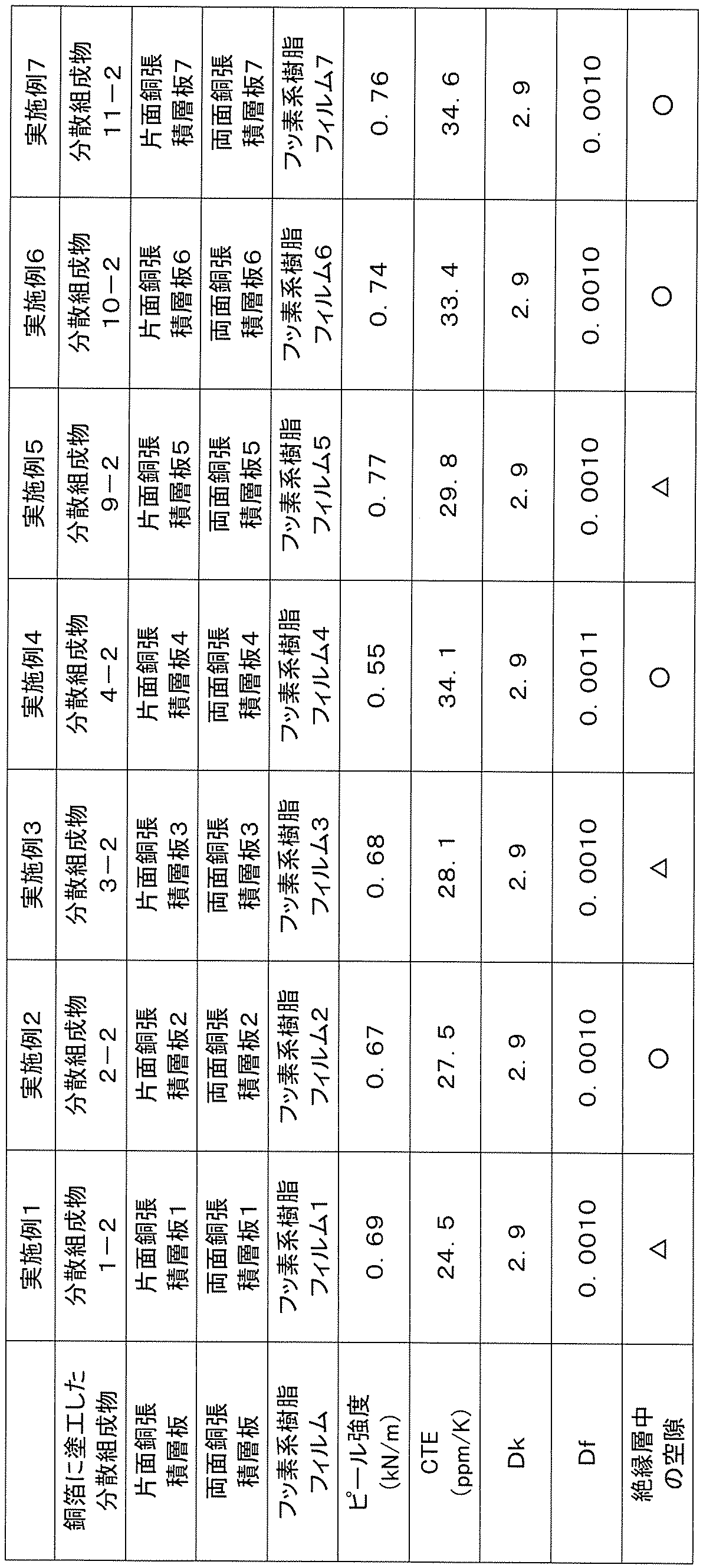
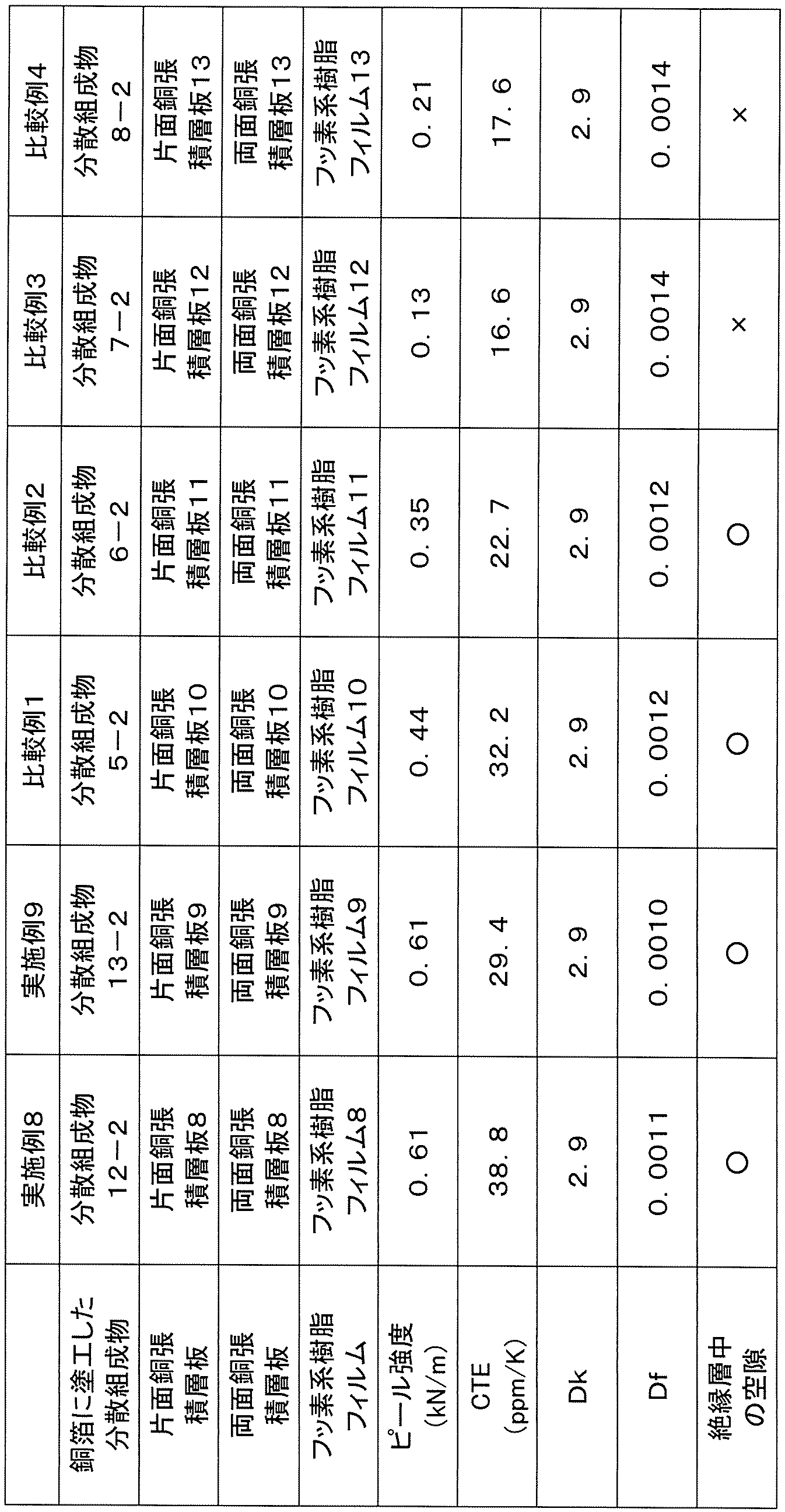
以上の結果から分かるように、比較例1~4に係る両面銅張積層板では、実施例に比べてピール強度が総じて約20~60%程度になってしまった。それに対して、実施例1~9では、ピール強度を十分に発現しながら、高周波領域での測定において比誘電率(Dk)及び誘電正接(Df)に優れたものを得ることができた。そのため、本発明によれば、低誘電特性、低誘電損出といった電気特性を有するフッ素系樹脂を用いながら、信頼性に優れた基板材料を得ることが可能になる。
Claims (8)
- フッ素系樹脂を含む樹脂成分(A)と無機フィラー(B)とを有する樹脂組成物であって、
(A)及び(B)の合計に対する(A)の質量割合が20~50%であると共に、(A)及び(B)の合計に対する(B)の質量割合が50~80%であり、また、(A)におけるフッ素系樹脂の質量割合が50%以上であり、
(B)は、3μm以下の粒子の体積割合が10%以上30%未満であり、体積基準での累積分布が50%を示すD50が8μm以上15μm以下あり、かつ、体積基準での累積分布が90%を示すD90が30μm以下であることを特徴とする、樹脂組成物。 - (A)におけるフッ素系樹脂の質量割合が70%以上であり、フッ素系樹脂がテトラフルオロエチレン-パーフルオロアルキルビニルエーテル共重合体である、請求項1に記載の樹脂組成物。
- (B)は、球状シリカであり、かつ、単一種の表面処理剤で表面処理されている、請求項1に記載の樹脂組成物。
- (B)は、3μm以下の粒子の体積割合が10%以上20%未満であり、体積基準での累積分布が50%を示すD50が8μm以上10μm以下であり、かつ、体積基準での累積分布が100%を示すD100が30μm以下である、請求項1に記載の樹脂組成物。
- (B)は、体積基準での累積分布が10%を示すD10が1.5μm未満である、請求項1に記載の樹脂組成物。
- 請求項1~5のいずれかに記載の樹脂組成物からなるフッ素系樹脂フィルム。
- 請求項1~5のいずれかに記載の樹脂組成物からなるフッ素系樹脂フィルムと金属箔とを備えたフッ素樹脂金属張積層体。
- 請求項7に記載のフッ素系樹脂金属張積層体を用いたプリント配線板。
Applications Claiming Priority (2)
| Application Number | Priority Date | Filing Date | Title |
|---|---|---|---|
| JP2022156600A JP2024050028A (ja) | 2022-09-29 | 2022-09-29 | 樹脂組成物及びこれを用いたフッ素系樹脂フィルム並びにフッ素系樹脂金属張積層体 |
| JP2022-156600 | 2022-09-29 |
Publications (1)
| Publication Number | Publication Date |
|---|---|
| WO2024070495A1 true WO2024070495A1 (ja) | 2024-04-04 |
Family
ID=90477263
Family Applications (1)
| Application Number | Title | Priority Date | Filing Date |
|---|---|---|---|
| PCT/JP2023/032033 Ceased WO2024070495A1 (ja) | 2022-09-29 | 2023-08-31 | 樹脂組成物及びこれを用いたフッ素系樹脂フィルム並びにフッ素系樹脂金属張積層体 |
Country Status (3)
| Country | Link |
|---|---|
| JP (1) | JP2024050028A (ja) |
| TW (1) | TW202413449A (ja) |
| WO (1) | WO2024070495A1 (ja) |
Citations (3)
| Publication number | Priority date | Publication date | Assignee | Title |
|---|---|---|---|---|
| JP2012527515A (ja) * | 2009-05-20 | 2012-11-08 | ヘクセル コーポレイション | 曲げ特性の向上したエポキシ樹脂 |
| WO2021049371A1 (ja) * | 2019-09-12 | 2021-03-18 | 日本電気硝子株式会社 | 立体造形用樹脂組成物 |
| US20220033617A1 (en) * | 2020-07-28 | 2022-02-03 | Saint-Gobain Performance Plastics Corporation | Dielectric substrate and method of forming the same |
-
2022
- 2022-09-29 JP JP2022156600A patent/JP2024050028A/ja active Pending
-
2023
- 2023-08-31 WO PCT/JP2023/032033 patent/WO2024070495A1/ja not_active Ceased
- 2023-09-04 TW TW112133463A patent/TW202413449A/zh unknown
Patent Citations (3)
| Publication number | Priority date | Publication date | Assignee | Title |
|---|---|---|---|---|
| JP2012527515A (ja) * | 2009-05-20 | 2012-11-08 | ヘクセル コーポレイション | 曲げ特性の向上したエポキシ樹脂 |
| WO2021049371A1 (ja) * | 2019-09-12 | 2021-03-18 | 日本電気硝子株式会社 | 立体造形用樹脂組成物 |
| US20220033617A1 (en) * | 2020-07-28 | 2022-02-03 | Saint-Gobain Performance Plastics Corporation | Dielectric substrate and method of forming the same |
Also Published As
| Publication number | Publication date |
|---|---|
| JP2024050028A (ja) | 2024-04-10 |
| TW202413449A (zh) | 2024-04-01 |
Similar Documents
| Publication | Publication Date | Title |
|---|---|---|
| JP7559767B2 (ja) | 非水系分散液、積層体の製造方法及び成形物 | |
| JP7616070B2 (ja) | 分散液、分散液の製造方法及び成形物 | |
| JP2022011017A (ja) | パウダー分散液及び積層体の製造方法 | |
| TW202404808A (zh) | 覆金屬積層板及其製造方法 | |
| JP7722194B2 (ja) | 積層体の製造方法及び液状組成物 | |
| CN115803390B (zh) | 粉体组合物及复合粒子 | |
| JP7635621B2 (ja) | 改質分散液の製造方法及び分散液 | |
| JP7468520B2 (ja) | 液状組成物 | |
| WO2024070495A1 (ja) | 樹脂組成物及びこれを用いたフッ素系樹脂フィルム並びにフッ素系樹脂金属張積層体 | |
| WO2023189795A1 (ja) | 分散組成物、フッ素系樹脂フィルム、金属張積層板及びその製造方法 | |
| JP7511117B2 (ja) | 複合粒子、複合粒子の製造方法、液状組成物、積層体の製造方法及びフィルムの製造方法 | |
| JP2025049784A (ja) | 金属張積層板及びその製造方法 | |
| WO2022259992A1 (ja) | シート | |
| JP7762314B2 (ja) | 分散組成物、フッ素系樹脂フィルム、金属張積層板及びその製造方法 | |
| JP2022061412A (ja) | 液状組成物の製造方法及び積層体の製造方法 | |
| JP7824044B2 (ja) | 分散組成物、その製造方法、フッ素系樹脂フィルムの製造方法、及び、金属張積層板の製造方法 | |
| CN116133853B (zh) | 分散液、复合粒子及复合粒子的制造方法 | |
| JP7635620B2 (ja) | 水系分散液、及び積層体の製造方法 | |
| JP7559497B2 (ja) | 分散液及び積層体の製造方法 | |
| JP7511124B2 (ja) | 分散液の製造方法および分散液 | |
| JP2024142752A (ja) | 長尺状塗工フィルムの製造方法及び金属張積層板の製造方法 | |
| WO2023054649A1 (ja) | 組成物、組成物の製造方法及びシートの製造方法 | |
| WO2023163025A1 (ja) | 組成物 | |
| JP2022072333A (ja) | テトラフルオロエチレン系ポリマーの組成物、該組成物を含む液状組成物、積層体およびフィルム | |
| JP2024142753A (ja) | 両面金属張積層板の製造方法 |
Legal Events
| Date | Code | Title | Description |
|---|---|---|---|
| 121 | Ep: the epo has been informed by wipo that ep was designated in this application |
Ref document number: 23871735 Country of ref document: EP Kind code of ref document: A1 |
|
| NENP | Non-entry into the national phase |
Ref country code: DE |
|
| 122 | Ep: pct application non-entry in european phase |
Ref document number: 23871735 Country of ref document: EP Kind code of ref document: A1 |