WO2024070229A1 - ロータ、回転電機、および駆動装置 - Google Patents
ロータ、回転電機、および駆動装置 Download PDFInfo
- Publication number
- WO2024070229A1 WO2024070229A1 PCT/JP2023/028530 JP2023028530W WO2024070229A1 WO 2024070229 A1 WO2024070229 A1 WO 2024070229A1 JP 2023028530 W JP2023028530 W JP 2023028530W WO 2024070229 A1 WO2024070229 A1 WO 2024070229A1
- Authority
- WO
- WIPO (PCT)
- Prior art keywords
- rotor
- hole
- rotor core
- rotation stopper
- fan
- Prior art date
- Legal status (The legal status is an assumption and is not a legal conclusion. Google has not performed a legal analysis and makes no representation as to the accuracy of the status listed.)
- Ceased
Links
Images





Classifications
-
- H—ELECTRICITY
- H02—GENERATION; CONVERSION OR DISTRIBUTION OF ELECTRIC POWER
- H02K—DYNAMO-ELECTRIC MACHINES
- H02K1/00—Details of the magnetic circuit
- H02K1/06—Details of the magnetic circuit characterised by the shape, form or construction
- H02K1/22—Rotating parts of the magnetic circuit
- H02K1/32—Rotating parts of the magnetic circuit with channels or ducts for flow of cooling medium
-
- H—ELECTRICITY
- H02—GENERATION; CONVERSION OR DISTRIBUTION OF ELECTRIC POWER
- H02K—DYNAMO-ELECTRIC MACHINES
- H02K9/00—Arrangements for cooling or ventilating
- H02K9/02—Arrangements for cooling or ventilating by ambient air flowing through the machine
- H02K9/04—Arrangements for cooling or ventilating by ambient air flowing through the machine having means for generating a flow of cooling medium
- H02K9/06—Arrangements for cooling or ventilating by ambient air flowing through the machine having means for generating a flow of cooling medium with fans or impellers driven by the machine shaft
Definitions
- the present invention relates to a rotor, a rotating electric machine, and a drive device.
- This application claims priority based on Japanese Patent Application No. 2022-157335, filed in Japan on September 30, 2022, the contents of which are incorporated herein by reference.
- a rotating electric machine in which an internal fan is disposed at the axial end of the rotor core, and the air sent by the internal fan flows through a flow hole provided in the rotor core.
- the internal fan is fixed to the rotating shaft (see, for example, Patent Document 1).
- one of the objects of the present invention is to provide a rotor, a rotating electric machine, and a drive unit that have a structure that can improve the efficiency of air blowing by a fan.
- One aspect of the rotor of the present invention is a rotor that can rotate around a central axis, and includes a rotor core and a fan that is arranged axially opposite the rotor core.
- the rotor core has an air hole that passes through the rotor core in the axial direction.
- the fan has an opening that is arranged opposite the air hole.
- the rotor core is provided with a first rotation stopper.
- the fan is provided with a second rotation stopper that contacts the first rotation stopper in the circumferential direction.
- One embodiment of the rotating electric machine of the present invention comprises the rotor described above and a stator that faces the rotor with a radial gap in between.
- One embodiment of the drive device of the present invention includes the above-mentioned rotating electric machine and a power transmission unit that transmits the power of the rotating electric machine.
- the efficiency of air blowing by a fan provided on a rotor in a rotating electric machine and a drive unit can be improved.
- FIG. 1 is a diagram illustrating a schematic diagram of a drive device according to a first embodiment.
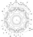
- FIG. 2 is a cross-sectional view showing the rotor in the first embodiment.
- FIG. 3 is a cross-sectional view showing a portion of the rotor in the first embodiment.
- FIG. 4 is a perspective view showing the fan and the retaining member according to the first embodiment.
- FIG. 5 is a perspective view showing the fan in the first embodiment, and is a view showing the fan from an angle different from that in FIG.
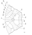
- FIG. 6 is a cross-sectional view showing a portion of a rotor according to the second embodiment.
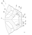
- FIG. 7 is a cross-sectional view showing a part of a rotor according to the third embodiment.
- FIG. 8 is a cross-sectional view showing a part of a rotor according to the fourth embodiment.
- FIG. 9 is a cross-sectional view showing a part of a rotor according to the fifth embodiment.
- the vertical direction is defined based on the positional relationship when the drive device of the embodiment is mounted on a vehicle positioned on a horizontal road surface.
- the relative positional relationship in the vertical direction described in the following embodiment only needs to be satisfied when the drive device is mounted on a vehicle positioned on a horizontal road surface.
- the XYZ coordinate system is appropriately shown as a three-dimensional Cartesian coordinate system.
- the Z axis direction is the vertical direction.
- the +Z side is the upper side in the vertical direction
- the -Z side is the lower side in the vertical direction.
- the upper side in the vertical direction is simply called the "upper side”
- the lower side in the vertical direction is simply called the "lower side”.
- the X axis direction is a direction perpendicular to the Z axis direction and is the front-to-rear direction of the vehicle on which the drive unit is mounted.
- the +X side is the front side of the vehicle
- the -X side is the rear side of the vehicle.
- the Y axis direction is a direction perpendicular to both the X axis direction and the Z axis direction, and is the left-to-right direction of the vehicle, i.e., the vehicle width direction.
- the +Y side is the left side of the vehicle
- the -Y side is the right side of the vehicle.
- the front-to-rear direction and the left-to-right direction are horizontal directions perpendicular to the vertical direction.
- the positional relationship in the front-rear direction is not limited to that in the following embodiment, and the +X side may be the rear side of the vehicle, and the -X side may be the front side of the vehicle.
- the +Y side is the right side of the vehicle, and the -Y side is the left side of the vehicle.
- parallel direction also includes substantially parallel directions
- perpendicular direction also includes substantially perpendicular directions.
- the central axis J is a virtual axis extending in a direction intersecting the vertical direction. More specifically, the central axis J extends in the Y-axis direction perpendicular to the vertical direction, that is, in the left-right direction of the vehicle.
- the direction parallel to the central axis J will be referred to simply as the "axial direction”
- the radial direction centered on the central axis J will be referred to simply as the "radial direction”
- the circumferential direction centered on the central axis J that is, around the axis of the central axis J, will be referred to simply as the "circumferential direction”.
- the left side (+Y side) will be referred to as the "one axial side”
- the right side (-Y side) will be referred to as the "other axial side”.
- a drive device 100 according to the present embodiment shown in Fig. 1 is a drive device mounted on a vehicle and rotates an axle 73.
- the vehicle on which the drive device 100 is mounted is a vehicle powered by a motor, such as a hybrid electric vehicle (HEV), a plug-in hybrid electric vehicle (PHV), or an electric vehicle (EV).
- the drive device 100 includes a rotating electric machine 60, a power transmission unit 70 that transmits the power of the rotating electric machine 60, and a housing 63 that accommodates the rotating electric machine 60 and the power transmission unit 70 therein.
- the rotating electric machine 60 is a motor.
- the housing 63 houses the rotating electric machine 60 and the power transmission unit 70 inside.
- the housing 63 has a motor housing 63a that houses the rotating electric machine 60 inside, and a gear housing 63b that houses the power transmission unit 70 inside.
- the motor housing 63a is connected to the other axial side (-Y side) of the gear housing 63b.
- the gear housing 63b contains oil O inside.
- the oil O is stored in a lower area inside the gear housing 63b.
- the oil O is used as a lubricant for the power transmission section 70.
- As the oil O for example, it is preferable to use an oil equivalent to an automatic transmission lubricant (ATF: Automatic Transmission Fluid) that has a relatively low viscosity in order to perform the function of a lubricant.
- ATF Automatic Transmission Fluid
- the power transmission unit 70 is connected to the rotating electric machine 60 and transmits the rotation of the rotor 10, which will be described later, to the axle 73 of the vehicle.
- the power transmission unit 70 has a reduction gear 71 connected to the rotating electric machine 60, and a differential gear 72 connected to the reduction gear 71.
- the differential gear 72 has a ring gear 72a.
- the torque output from the rotating electric machine 60 is transmitted to the ring gear 72a via the reduction gear 71.
- the lower end of the ring gear 72a is immersed in oil O stored in the gear housing 63b. As the ring gear 72a rotates, the oil O is scooped up.
- the scooped up oil O is supplied to the reduction gear 71 and the differential gear 72, for example, as lubricating oil.
- the rotating electric machine 60 includes a rotor 10 that can rotate around a central axis J, and a stator 61 that faces the rotor 10 with a gap in the radial direction.
- the stator 61 is located radially outside the rotor 10.
- the stator 61 includes a stator core 61a and a coil assembly 61b attached to the stator core 61a.
- the coil assembly 61b includes a plurality of coils 61c attached to the stator core 61a.
- the coil assembly 61b may include a bundling member that bundles the coils 61c, or may include a crossover wire that connects the coils 61c together.
- the coil assembly 61b includes coil ends 61d and 61e that protrude in the axial direction beyond the stator core 61a.
- the coil end 61d protrudes toward one axial side (+Y side) beyond the stator core 61a.
- the coil end 61e protrudes toward the other axial side (-Y side) beyond the stator core 61a.
- the rotor 10 has a rotor shaft 20, a rotor core 30, and a plurality of magnets 40.
- the rotor shaft 20 extends in the axial direction along the central axis J.
- a reduction gear 71 is connected to one end of the rotor shaft 20 in the axial direction (+Y side).
- the rotor shaft 20 is a cylindrical hollow shaft centered on the central axis J.
- the rotor core 30 is fixed to the outer peripheral surface of the rotor shaft 20.
- the rotor core 30 is generally cylindrical and centered on the central axis J.
- the rotor core 30 has a through hole 30h that passes through the rotor core 30 in the axial direction.
- the central axis J passes through the inside of the through hole 30h.
- the through hole 30h is a circular hole centered on the central axis J.
- the rotor shaft 20 passes through the through hole 30h in the axial direction.
- the inner peripheral surface of the through hole 30h is fixed to the outer peripheral surface of the rotor shaft 20.
- the rotor shaft 20 is press-fitted into the through hole 30h.
- the rotor core 30 is made of a magnetic material. Although not shown in the figure, the rotor core 30 is formed by stacking a plurality of plate members in the axial direction.
- the plate members are, for example, electromagnetic steel plates.
- the rotor core 30 has a plurality of core pieces 30p arranged in line in the axial direction. Each of the plurality of core pieces 30p is formed by stacking a plurality of the above-mentioned plate members in the axial direction.
- the core pieces 30p adjacent in the axial direction are in contact with each other. Note that a separate plate-shaped member may be sandwiched between the core pieces 30p adjacent in the axial direction. In the example of FIG. 1, three core pieces 30p are provided.
- the plurality of core pieces 30p are arranged with their circumferential positions shifted from each other. In other words, in this embodiment, a step skew is provided in the rotor 10.
- the rotor core 30 has a plurality of magnet holding portions 31 arranged in a line in the circumferential direction.
- the plurality of magnet holding portions 31 are provided on the radially outer portion of the rotor core 30.
- the plurality of magnet holding portions 31 are arranged at equal intervals around the circumference. In this embodiment, eight magnet holding portions 31 are provided.
- the multiple magnet holding portions 31 each have a pair of magnet holes 51a, 51b adjacent to each other in the circumferential direction.
- the rotor core 30 has a pair of magnet holes 51a, 51b.
- the pair of magnet holes 51a, 51b penetrate the rotor core 30 in the axial direction.
- the pair of magnet holes 51a, 51b may also be holes that have bottoms at the axial ends.
- One magnet 40 is disposed in each of the two magnet holes 51a, 51b in each magnet holding portion 31.
- the type of magnet 40 is not particularly limited.
- the magnet 40 may be, for example, a neodymium magnet or a ferrite magnet.
- the magnet 40 is, for example, a rectangular parallelepiped that is long in the axial direction.
- the magnet 40 extends, for example, from one axial end of the rotor core 30 to the other axial end.
- the magnets 40 include a pair of magnets 41a, 41b arranged in a pair of magnet holes 51a, 51b.
- the pair of magnets 41a, 41b is fixed in the pair of magnet holes 51a, 51b.
- the method of fixing each magnet 41a, 41b in each magnet hole 51a, 51b is not particularly limited.
- each magnet 41a, 41b may be fixed in each magnet hole 51a, 51b by crimping a part of the rotor core 30, or may be fixed in each magnet hole 51a, 51b by resin filled in the part of each magnet hole 51a, 51b other than the part where the magnets 41a, 41b are arranged, or may be fixed in each magnet hole 51a, 51b by a foam sheet arranged in the part of each magnet hole 51a, 51b other than the part where the magnets 41a, 41b are arranged.
- a magnetic pole portion 10P is formed by one magnet holding portion 31 and a pair of magnets 41a, 41b arranged in a pair of magnet holes 51a, 51b provided in one magnet holding portion 31.
- a plurality of magnetic pole portions 10P are arranged at equal intervals around one circumference along the circumferential direction. In this embodiment, eight magnetic pole portions 10P are provided.
- the plurality of magnetic pole portions 10P include a plurality of magnetic pole portions 10N having a magnetic pole with a north pole on the outer peripheral surface of the rotor core 30 and a plurality of magnetic pole portions 10S having a magnetic pole with a south pole on the outer peripheral surface of the rotor core 30. In this embodiment, four magnetic pole portions 10N and four magnetic pole portions 10S are provided.
- the four magnetic pole portions 10N and four magnetic pole portions 10S are arranged alternately along the circumferential direction.
- the configuration of each magnetic pole portion 10P is the same except that the magnetic poles on the outer peripheral surface of the rotor core 30 are different and the circumferential positions are different.
- the magnet hole 51a and the magnet hole 51b are arranged on either side of the first virtual line Ld in the circumferential direction.
- the first virtual line Ld is a virtual line that passes through the circumferential center between the pair of magnet holes 51a, 51b and extends in the radial direction.
- the first virtual line Ld is a magnetic pole center line that passes through the circumferential center of the magnetic pole portion 10P.
- the circumferential center of the magnetic pole portion 10P is the circumferential center of the magnet holding portion 31.
- the first virtual line Ld is provided for each magnetic pole portion 10P. When viewed in the axial direction, the first virtual line Ld passes on the d-axis of the rotor 10.
- the direction in which the first virtual line Ld extends is the d-axis direction of the rotor 10.
- the magnet hole 51a and the magnet hole 51b are arranged in line symmetry with the first virtual line Ld as the axis of symmetry.
- the pair of magnet holes 51a, 51b extend in a direction that separates them from each other in the circumferential direction as they move from the radially inner side to the radially outer side when viewed in the axial direction. In other words, the circumferential distance between magnet holes 51a and 51b increases from the radially inner side to the radially outer side.
- the pair of magnet holes 51a, 51b are arranged along a V-shape that widens in the circumferential direction as it moves radially outward when viewed in the axial direction.
- the magnet hole 51a has a magnet accommodating hole portion 51c, an inner hole portion 51d, and an outer hole portion 51e.
- the magnet accommodating hole portion 51c is a rectangular hole that is long in the direction in which the magnet hole 51a extends when viewed in the axial direction.
- the inner hole portion 51d is connected to the radially inner end of the end of the magnet accommodating hole portion 51c in the direction in which the magnet accommodating hole portion 51c extends when viewed in the axial direction.
- the outer hole portion 51e is connected to the radially outer end of the end of the magnet accommodating hole portion 51c in the direction in which the magnet accommodating hole portion 51c extends when viewed in the axial direction.
- the magnet hole 51b has a magnet accommodating hole portion 51f, an inner hole portion 51g, and an outer hole portion 51h.
- the magnet accommodating hole portion 51f is a rectangular hole that is long in the direction in which the magnet hole 51b extends when viewed in the axial direction.
- the inner hole portion 51g is connected to the radially inner end of the end of the magnet accommodating hole portion 51f in the direction in which the magnet accommodating hole portion 51f extends when viewed in the axial direction.
- the outer hole portion 51h is connected to the radially outer end of the end of the magnet accommodating hole portion 51f in the direction in which the magnet accommodating hole portion 51f extends when viewed in the axial direction.
- the inner hole portion 51d and the inner hole portion 51g are arranged circumferentially spaced apart from each other across the first imaginary line Ld. When viewed in the axial direction, the edges of the inner hole portion 51d and the inner hole portion 51g that are closer to the other inner hole portion each extend linearly along the first imaginary line Ld.
- the pair of magnets 41a, 41b arranged in the pair of magnet holes 51a, 51b are arranged along a V-shape that expands in the circumferential direction as it goes radially outward when viewed in the axial direction.
- the magnet 41a is arranged in the magnet accommodating hole portion 51c of the magnet hole 51a.
- the magnet 41b is arranged in the magnet accommodating hole portion 51f of the magnet hole 51b.
- the inner holes 51d, 51g and the outer holes 51e, 51h are, for example, hollow portions, and each constitutes a flux barrier portion.
- the inner holes 51d, 51g and the outer holes 51e, 51h may be filled with a non-magnetic material such as resin, and the flux barrier portion may be constituted by each hole and the non-magnetic material such as resin filled in each hole.
- the "flux barrier portion" is a portion that can suppress the flow of magnetic flux. In other words, magnetic flux does not easily pass through each flux barrier portion.
- the "direction in which the magnet hole extends when viewed in the axial direction” refers to the direction in which the long side of the rectangular magnet accommodating hole portion extends when viewed in the axial direction, for example, when the magnet accommodating hole portion in which the magnet is accommodated is rectangular when viewed in the axial direction, such as magnet holes 51a and 51b in this embodiment.
- the "direction in which the magnet hole 51a extends when viewed in the axial direction” refers to the direction in which the long side of the rectangular magnet accommodating hole portion 51c extends when viewed in the axial direction.
- the rotor core 30 has ventilation holes 80 that penetrate the rotor core 30 in the axial direction.
- the ventilation holes 80 are provided at positions overlapping with a second virtual line Lq that passes through the circumferential center between circumferentially adjacent magnet holding portions 31 when viewed in the axial direction and extends in the radial direction.
- the second virtual line Lq passes through the q axis of the rotor 10.
- the direction in which the second virtual line Lq extends is the q axis direction of the rotor 10.
- the second virtual line Lq is provided between each pair of magnet holding portions 31.
- the direction in which the first virtual line Ld extends and the direction in which the second virtual line Lq extends intersect with each other.
- the first virtual line Ld and the second virtual line Lq are provided alternately along the circumferential direction.
- each ventilation hole 80 is disposed radially inward between circumferentially adjacent magnet holding portions 31. As shown in FIG. 3, each ventilation hole 80 is located radially inward between magnet hole 51a in one magnet holding portion 31 and magnet hole 51b in the other magnet holding portion 31 of the circumferentially adjacent magnet holding portions 31.
- a second imaginary line Lq passes through the circumferential center of the ventilation hole 80.
- the ventilation hole 80 has a shape that is line-symmetrical with respect to the second imaginary line Lq that passes through the ventilation hole 80 as the axis of symmetry.
- the ventilation hole 80 has a first hole portion 81 and a second hole portion 82.
- the first hole portion 81 has a generally pentagonal shape with rounded corners when viewed in the axial direction.
- the first hole portion 81 is provided at a position that overlaps with the second virtual line Lq when viewed in the axial direction.
- the first hole portion 81 has a shape that is line-symmetrical with respect to the second virtual line Lq that passes through the first hole portion 81 when viewed in the axial direction.
- the inner wall of the first hole portion 81 has a pair of first inner wall portions 81a, a pair of second inner wall portions 81b, and a third inner wall portion 81c.
- the pair of first inner wall portions 81a are arranged on either side of the second virtual line Lq in the circumferential direction when viewed in the axial direction.
- the pair of first inner wall portions 81a extend in directions that move away from each other in the circumferential direction as they move radially inward when viewed in the axial direction.
- One of the pair of first inner wall portions 81a is located radially inside the magnet hole 51a and extends in approximately the same direction as the magnet hole 51a extends when viewed in the axial direction.
- the other of the pair of first inner wall portions 81a is located radially inside the magnet hole 51b and extends in approximately the same direction as the magnet hole 51b extends when viewed in the axial direction.
- the pair of second inner wall portions 81b extend radially inward from the respective radial inner ends of the pair of first inner wall portions 81a when viewed in the axial direction.
- the third inner wall portion 81c extends in an arc shape centered on the central axis J when viewed in the axial direction.
- the third inner wall portion 81c connects the radial inner ends of the pair of second inner wall portions 81b.
- the second hole portion 82 is located radially outside the first hole portion 81.
- the second hole portion 82 is connected to the radially outer end of the first hole portion 81.
- the second hole portion 82 is approximately circular when viewed in the axial direction.
- the second hole portion 82 is provided at a position overlapping with the second virtual line Lq when viewed in the axial direction.
- the second virtual line Lq passes through the center of the second hole portion 82.
- the second hole portion 82 has a shape that is line-symmetrical with respect to the second virtual line Lq that passes through the second hole portion 82 as an axis of symmetry.
- the second hole portion 82 is located circumferentially between the magnet hole 51a in one magnet holding portion 31 and the magnet hole 51b in the other magnet holding portion 31 of the magnet holding portions 31 adjacent in the circumferential direction. More specifically, the second hole 82 is located circumferentially between the magnet accommodating hole 51c in one of the magnet holding parts 31 and the magnet accommodating hole 51f in the other of the magnet holding parts 31 that are adjacent in the circumferential direction.
- the inner wall of the second hole portion 82 is C-shaped and opens radially inward when viewed in the axial direction. When viewed in the axial direction, both ends of the inner wall of the second hole portion 82 extending in a C-shape are connected to the radially outer ends of the pair of first inner wall portions 81a.
- the circumferential dimension of the second hole portion 82 is smaller than the circumferential dimension of the first hole portion 81.
- the second hole portion 82 corresponds to a "first rotation stopper" provided in the rotor core 30.
- multiple second hole portions 82 as first rotation stoppers are provided at intervals in the circumferential direction.
- the circumferential dimension of the connection 80a between the first hole 81 and the second hole 82 is smaller than the circumferential dimension of the first hole 81 and the circumferential dimension of the second hole 82.
- the air vent 80 has a shape that is narrowed in the circumferential direction at the connection 80a between the first hole 81 and the second hole 82.
- a pair of protrusions 83a, 83b are provided on both circumferential sides of the connection 80a.
- the pair of protrusions 83a, 83b are provided on the inner wall of the air vent 80.
- the pair of protrusions 83a, 83b are arranged opposite each other in the circumferential direction and protrude in the circumferential direction toward the other protrusion.
- the radially outer surfaces of the pair of protrusions 83a, 83b form part of the inner surface of the second hole 82.
- the rotor 10 includes a fan 90 arranged axially opposite the rotor core 30.
- the fan 90 is arranged on each side of the rotor core 30 in the axial direction.
- the pair of fans 90 are arranged radially inside the pair of coil ends 61d, 61e.
- the pair of fans 90 have the same shape.
- the pair of fans 90 are attached to the axial end faces of the rotor core 30 in opposite directions to each other in the axial direction.
- the pair of fans 90 are attached at different angles around the central axis J with respect to the rotor core 30.
- the material constituting the fan 90 is, for example, an aluminum alloy.
- the fan 90 is formed, for example, by die casting.
- the material constituting the fan 90 may be a metal other than an aluminum alloy, or may be a resin material.
- the fan 90 located on the other axial side (-Y side) of the rotor core 30 is described as a representative of the pair of fans 90.
- the side closer to the center of the rotor core 30 in the axial direction is called the "axial inner side”
- the side farther from the center of the rotor core 30 in the axial direction is called the "axial outer side”.
- the side on which the rotor core 30 is located relative to the fan 90 is the axial inner side
- the side opposite to the side on which the rotor core 30 is located relative to the fan 90 is the axial outer side.
- the axial inner side is one axial side (+Y side)
- the axial outer side is the other axial side (-Y side).
- the fan 90 is an annular member surrounding the central axis J. More specifically, the fan 90 is annular about the central axis J.
- the rotor shaft 20 passes axially through the radially inner side of the fan 90.
- the fan 90 has a fan main body 91, a rib portion 93, and a visor portion 94.
- the fan main body 91 is an annular portion surrounding the central axis J. As shown in Figure 1, the axially inner surface of the fan main body 91 contacts the axial end face of the rotor core 30.
- the fan body 91 has a first opening 95 and a second opening 96 that penetrate the fan body 91 in the axial direction. That is, the fan 90 has a first opening 95 and a second opening 96.
- the first opening 95 and the second opening 96 are openings that are arranged opposite the air vent 80.
- the first openings 95 and the second openings 96 are alternately arranged in the circumferential direction.
- the first openings 95 and the second openings 96 are approximately arc-shaped extending in the circumferential direction when viewed in the axial direction.
- the first opening 95 and the second opening 96 are disposed axially opposite the ventilation hole 80 and are connected to the ventilation hole 80.
- One of the first opening 95 and the second opening 96 in the fan 90 located on one axial side is connected to the end of the ventilation hole 80 on one axial side (+Y side).
- the other of the first opening 95 and the second opening 96 in the fan 90 located on the other axial side is connected to the end of the ventilation hole 80 on the other axial side (-Y side).
- the first opening 95 is connected to one of both axial ends of the ventilation hole 80
- the second opening 96 is connected to the other of both axial ends of the ventilation hole 80.
- the multiple ventilation holes 80 include a ventilation hole 80 whose end on one axial side (+Y side) is connected to the first opening 95 and whose end on the other axial side (-Y side) is connected to the second opening 96, and a ventilation hole 80 whose end on one axial side is connected to the second opening 96 and whose end on the other axial side is connected to the first opening 95.
- the ventilation hole 80 whose end on one axial side is connected to the first opening 95 and whose end on the other axial side is connected to the second opening 96 and the ventilation hole 80 whose end on one axial side is connected to the second opening 96 and whose end on the other axial side is connected to the first opening 95 are arranged alternately in the circumferential direction.
- the rib portions 93 are provided between the first opening 95 and the second opening 96 that are adjacent in the circumferential direction.
- the rib portions 93 protrude axially outward from the fan main body 91.
- the rib portions 93 extend in the radial direction.
- the eaves portion 94 is disposed facing the axially outer side (-Y side) of the radially inner portion of the second opening 96.
- the eaves portion 94 extends in the circumferential direction.
- the eaves portion 94 circumferentially connects the rib portions 93 located on both sides of the circumferential direction of the second opening 96.
- the air can be suitably blown out from the second opening 96 when the fan 90 rotates, it is possible to easily generate negative pressure inside the part of the ventilation hole 80 that is connected to the second opening 96. This makes it easier to suck air into the ventilation hole 80 through the first opening 95. Therefore, it is easier to make the air flow through the ventilation hole 80 suitably.
- the air blown out from the second opening 96 of the fan 90 on one axial side (+Y side) hits the coil end 61d and is then sucked into the first opening 95 of the fan 90 on one axial side.
- the air sucked into the first opening 95 of the fan 90 on one axial side flows through the ventilation hole 80 to the other axial side (-Y side) and is blown out from the second opening 96 of the fan 90 on the other axial side.
- the air blown out from the second opening 96 of the fan 90 on the other axial side hits the coil end 61e and is then sucked into the first opening 95 of the fan 90 on the other axial side.
- the air sucked into the first opening 95 of the fan 90 on the other axial side flows through the ventilation hole 80 to the one axial side and is blown out from the second opening 96 of the fan 90 on the one axial side.
- the rotor 10 rotates and the fan 90 rotates, circulating the air in the motor housing 63a and cooling the rotor 10 and the stator 61.
- the fan 90 is provided with a second rotation stopper 92.
- the second rotation stopper 92 is columnar and protrudes axially inward (+Y side) from the fan main body 91.
- the second rotation stopper 92 protrudes axially toward the rotor core 30.
- the second rotation stopper 92 is cylindrical and extends axially. The second rotation stopper 92 protrudes axially inward from the circumferential center of the radially outer portion of the inner edge of the first opening 95.
- the second rotation stopper 92 is inserted into the second hole 82 of the ventilation hole 80.
- the second rotation stopper 92 is fitted into the second hole 82 and contacts the inner surface of the second hole 82 in the circumferential direction.
- the second hole 82 is the first rotation stopper with which the second rotation stopper 92 contacts in the circumferential direction.
- the fan 90 is provided with the second rotation stopper 92 that contacts in the circumferential direction with the second hole 82 as the first rotation stopper. Therefore, the second hole 82 and the second rotation stopper 92, which are the first rotation stopper, prevent the fan 90 and the rotor core 30 from rotating relative to each other in the circumferential direction.
- the first opening 95 and the second opening 96 in the fan 90 can be suitably prevented from being misaligned in the circumferential direction with respect to the ventilation hole 80 in the rotor core 30.
- This allows air to flow easily through the first opening 95 and the second opening 96 into the vent hole 80, improving the efficiency of the air blowing by the fan 90.
- This allows the rotor 10 and the stator 61 to be cooled effectively by the air blown by the fan 90.
- the first rotation stopper can be easily provided on the rotor core 30 by changing the shape of the plate members to be punched out.
- the first rotation stopper can be provided on the rotor core 30, which is made by stacking the plate members, without performing additional processing. As a result, it is possible to suppress an increase in the number of steps required for manufacturing the rotor 10, and to suppress an increase in the manufacturing cost of the rotor 10.
- the first rotation stopper is a hole formed by a part of the vent hole 80, and the second rotation stopper 92 protrudes axially toward the rotor core 30 and is inserted into the vent hole 80, which is the first rotation stopper. Therefore, a part of the vent hole 80 can be used as the first rotation stopper that contacts the second rotation stopper 92 in the circumferential direction.
- This makes it possible to easily manufacture the rotor core 30 without having to provide a hole as the first rotation stopper into which the second rotation stopper 92 is inserted, in addition to the vent hole 80.
- the second hole portion 82 which is the first rotation stop portion, is the radially outer end of the ventilation hole 80.
- the first rotation stop portion is formed by the radially outer end of the ventilation hole 80. Therefore, it is possible to move the radial positions of the first rotation stop portion and the second rotation stop portion 92 further radially outward while using a part of the ventilation hole 80 as the first rotation stop portion. This allows the fan 90 to be supported circumferentially relative to the rotor core 30 relatively radially outward. Therefore, the fan 90 can be stably attached while preventing relative rotation with respect to the rotor core 30.
- protrusions 83a and 83b are provided on the inner wall of the ventilation hole 80 in which the second hole portion 82 serving as the first rotation stopper is provided.
- the protrusions 83a and 83b form part of the inner surface of the second hole portion 82 serving as the first rotation stopper. In this way, by providing the protrusions 83a and 83b on the inner wall of the ventilation hole 80, it is possible to easily create the first rotation stopper by partitioning off part of the ventilation hole 80.
- the second hole portion 82 as the first rotation stopper is provided in each of the multiple ventilation holes 80. Therefore, for example, compared to a case where the second hole portion 82 is provided only in some of the ventilation holes 80, it is possible to suppress the variation in the flow of magnetic flux around each ventilation hole 80. This makes it possible to suitably suppress the variation in the magnetic characteristics in the circumferential direction of the rotor 10.
- the second hole portion 82 is provided in each ventilation hole 80, it is possible to select which second hole portion 82 the second rotation stopper 92 is inserted into depending on the circumferential angle at which the fan 90 is attached to the rotor core 30.
- each second rotation stopper 92 of each fan 90 can be suitably inserted into the second hole portion 82 provided in the rotor core 30 as the first rotation stopper.
- the second hole portion 82 serving as the first rotation stopper is provided at a position overlapping with the second imaginary line Lq that extends radially through the circumferential center between circumferentially adjacent magnet holding portions 31 when viewed in the axial direction. Therefore, compared to when the first rotation stopper is provided in the magnet holding portion 31, it is possible to suppress interference of the first rotation stopper with the magnet holes 51a, 51b and magnets 41a, 41b provided in the magnet holding portion 31.
- the axial dimension of the second rotation stopper 92 is smaller than the axial dimension of the core piece 30p. Therefore, the second rotation stopper 92 inserted into the second hole 82 is not positioned across the portions of the second hole 82 that are provided in the two core pieces 30p. As a result, even if the core pieces 30p are arranged circumferentially offset to provide a step skew to the rotor 10, it is not necessary to insert the second rotation stopper 92 into the portions of the second hole 82 that are arranged circumferentially offset. Therefore, even if the core pieces 30p are arranged circumferentially offset, it is possible to easily insert the second rotation stopper 92 into the second hole 82.
- the second rotation stopper 92 is fitted into the second hole 82, which serves as the first rotation stopper. This allows the second rotation stopper 92 to be appropriately brought into contact with the second hole 82 in the circumferential direction, preventing the fan 90 from rotating relative to the rotor core 30 and allowing the fan 90 to be attached more stably.
- multiple second rotation stoppers 92 are provided at intervals in the circumferential direction. Therefore, the multiple second rotation stoppers 92 can more stably mount the fan 90 while preventing relative rotation with respect to the rotor core 30.
- the number of second rotation stoppers 92 is less than the number of second holes 82 as first rotation stoppers. Therefore, even if the second holes 82 and the second rotation stoppers 92 are slightly misaligned due to tolerances or the like, each of the multiple second rotation stoppers 92 can be easily inserted into the second hole 82 compared to a case where the second rotation stoppers 92 must be inserted into all of the second hole 82.
- the second rotation stopper portions 92 are provided as a pair, radially sandwiching the central axis J.
- the pair of second rotation stopper portions 92 are inserted into the second hole portions 82 of the pair of air holes 80 arranged radially sandwiching the central axis J.
- the rotor 10 is provided with a retaining member 23.
- the retaining member 23 is annular and surrounds the central axis J. More specifically, the retaining member 23 is annular and centered on the central axis J.
- the retaining member 23 is fixed to the outer peripheral surface of the rotor shaft 20.
- the rotor shaft 20 is press-fitted inside the retaining member 23.
- a pair of anti-slip members 23 are provided with an axial gap between them.
- the pair of anti-slip members 23 are arranged to sandwich the rotor core 30 and the pair of fans 90 arranged to sandwich the rotor core 30 in the axial direction.
- the anti-slip member 23 located on one axial side (+Y side) sandwiches the fan 90 located on one axial side between itself and the rotor core 30.
- the anti-slip member 23 located on the other axial side (-Y side) sandwiches the fan 90 located on the other axial side between itself and the rotor core 30.
- each fan 90 is located axially between the rotor core 30 and the anti-slip member 23.
- the anti-slip member 23 can prevent the fan 90 from moving in the axial direction away from the rotor core 30. This allows the fan 90 to be suitably positioned in the axial direction relative to the rotor core 30.
- the axially inner surface of the anti-slip member 23 is in contact with the fan 90.
- the vent hole 280 of the rotor core 230 is different from the vent hole 80 of the first embodiment in that it does not have the second hole portion 82 and is composed of only the first hole portion 281.
- the first hole portion 281 has a shape substantially similar to that of the first hole portion 81 in the first embodiment.
- the inner wall of the first hole portion 281 has a pair of first inner wall portions 81a, a pair of second inner wall portions 81b, and a third inner wall portion 81c, similar to the inner wall of the first hole portion 81 in the first embodiment.
- the pair of first inner wall portions 81a are connected to each other at the radially outer end portions.
- a pair of protrusions 283a, 283b are provided on the inner wall of the ventilation hole 280.
- the pair of protrusions 283a, 283b are provided on the radially outer portions of the pair of first inner wall portions 81a of the first hole portion 281, respectively.
- the pair of protrusions 283a, 283b are arranged facing each other in the circumferential direction and protrude in the circumferential direction toward the other protrusion.
- a gap is provided between the pair of protrusions 283a, 283b.
- the pair of protrusions 283a, 283b form the first rotation stopper 281d, which is a radially outer end of the first hole 281 and is separated from the other parts of the ventilation hole 280.
- the first rotation stopper 281d is generally diamond-shaped when viewed in the axial direction.
- the second rotation stopper 292 of the fan 290 is inserted into the first rotation stopper 281d.
- the second rotation stopper 292 is similar to the second rotation stopper 92 of the first embodiment, except for the difference in the radial position.
- the protrusions 283a, 283b form part of the inner surface of the first rotation stopper 281d.
- the radially outer surfaces of the protrusions 283a, 283b form the radially inner inner surface of the first rotation stopper 281d.
- the protrusions 283a, 283b are provided on the inner wall of the ventilation hole 280 to separate a part of the ventilation hole 280, and the first rotation stopper 281d can be easily made.
- the vent hole 380 of the rotor core 330 consists only of a first hole portion 381.
- the first hole portion 381 has a shape similar to that of the first hole portion 281 of the second embodiment, except that the protrusions 283a, 283b are not provided on the inner wall.
- the radially inner portion of the first hole portion 381 is a first rotation stopper portion 381d.
- the second rotation stopper 392 of the fan 390 has a pair of pillars 392a spaced apart in the circumferential direction.
- the pair of pillars 392a extend in the axial direction.
- the pair of pillars 392a are substantially rectangular and extend in the radial direction.
- the pair of pillars 392a are inserted into the first rotation stopper 381d.
- the pair of pillars 392a are arranged circumferentially opposite each other at portions located on both circumferential sides of the inner surface of the first rotation stopper 381d. Therefore, the second rotation stopper 392 can be stably contacted in the circumferential direction with the first rotation stopper 381d via the pair of pillars 392a.
- the pair of pillars 392a face each of the pair of second inner wall portions 81b in the circumferential direction.
- the pair of pillars 392a are in circumferential contact with each of the pair of second inner wall portions 81b.
- the shape of the rotor core 430 is similar to the shape of the rotor core 330 of the third embodiment.
- the radially outer end of the first hole portion 381 of the air hole 380 is a first rotation stop portion 481d.
- the second rotation stop portion 492 of the fan 490 has a generally triangular prism shape extending in the axial direction.
- the second rotation stop portion 492 is inserted into the first rotation stop portion 481d.
- the second rotation stop portion 492 is located between the radially outer ends of the pair of first inner wall portions 81a.
- the second rotation stop portion 492 is in circumferential contact with each of the pair of first inner wall portions 81a.
- the second rotation stop portion 492 is in contact with the connection portion between the pair of first inner wall portions 81a from the radially inner side.
- the rotor core 530 has a hole 580 that opens to the axial end surface of the rotor core 530.
- the hole 580 may be a hole that penetrates the rotor core 530 in the axial direction, or may be a hole that has a bottom at the axial end.
- the hole 580 is substantially circular when viewed in the axial direction.
- the second rotation stopper 592 in the fan 590 of this embodiment protrudes in the axial direction toward the rotor core 530 and is inserted into the hole 580 as the first rotation stopper.
- the second rotation stopper 592 is similar to the second rotation stopper 92 of the first embodiment, except for the difference in position.
- the hole 580 is located at a different position from the ventilation hole 380.
- the first rotation stopper is formed by the hole 580. Therefore, by providing the hole 580 separately from the ventilation hole 380, the first rotation stopper can be provided regardless of the position of the ventilation hole 380. This improves the degree of freedom in locating the first rotation stopper.
- the ventilation hole 380 in this embodiment does not have a first rotation stopper.
- the hole 580 serving as the first rotation stopper is provided in the magnet holding portion 531.
- the hole 580 serving as the first rotation stopper is located circumferentially between the pair of magnet holes 51a, 51b.
- the hole 580 serving as the first rotation stopper is provided at a position overlapping the first virtual line Ld when viewed in the axial direction.
- By arranging the hole 580 in such a position it is possible to further prevent the magnetic flux flowing through the rotor core 530 from being obstructed by the hole 580.
- the center of the hole 580 overlaps with the first virtual line Ld.
- the hole 580 serving as the first rotation prevention portion is provided on the radial outer edge of the rotor core 530. This allows the fan 590 to be more suitably supported in the circumferential direction relative to the rotor core 530 on the radial outer side, and allows the fan 590 to be more stably attached while preventing relative rotation with respect to the rotor core 530.
- the position of the hole 580 as the first rotation stopper is not particularly limited as long as it is a position different from the air vent 380.
- the hole 580 may be provided at the position of the hole 680 shown by the two-dot chain line in FIG. 9.
- the hole 680 is provided at a position overlapping with the second virtual line Lq when viewed in the axial direction.
- the center of the circular hole 680 overlaps with the second virtual line Lq when viewed in the axial direction.
- the hole 680 is provided at the radial outer edge of the rotor core 530.
- the hole 680 is located circumferentially between the outer hole 51e of the magnet hole 51a in one magnet holding portion 531 and the outer hole 51h of the magnet hole 51b in the other magnet holding portion 531, among the magnet holding portions 531 adjacent in the circumferential direction.
- the hole 680 is arranged at a distance from the radial outer side of the air vent 380.
- the present invention is not limited to the above-described embodiment, and other configurations and methods may be adopted within the scope of the technical concept of the present invention.
- the first rotation stopper may have any configuration provided that it is provided on the rotor core and makes circumferential contact with the second rotation stopper.
- the second rotation stopper may have any configuration provided that it is provided on the fan and makes circumferential contact with the first rotation stopper.
- the second rotation stopper may be a hole provided in the fan, and the first rotation stopper may protrude axially toward the fan and be inserted into the hole.
- the number of first rotation stopper parts and the number of second rotation stopper parts are not particularly limited, as long as they are one or more each.
- the number of first rotation stopper parts and the number of second rotation stopper parts may be the same as each other.
- the position of the second rotation stopper in the fan is not particularly limited.
- the second rotation stopper 92 may protrude in the axial direction from the inner edge of the second opening 96, or may protrude in the axial direction from a portion of the fan body 91 other than the first opening 95 and the second opening 96.
- the fan may have any configuration as long as it has an opening disposed opposite the vent and is provided with a second rotation stopper. Only one fan may be provided. The fan may be positioned in the axial direction relative to the rotor core in any manner.
- the magnet holes in the rotor core may be arranged in any manner.
- the rotor core may have other magnet holes located radially outward of the pair of magnet holes.
- the other magnet holes may be a pair of magnet holes arranged along a V-shape when viewed in the axial direction, similar to the pair of magnet holes in the above-described embodiment, or may be magnet holes extending in a direction perpendicular to the radial direction. If the other magnet holes are magnet holes extending in a direction perpendicular to the radial direction, the pair of magnet holes in the above-described embodiment and the other magnet holes may be arranged along a ⁇ shape when viewed in the axial direction.
- the rotating electric machine to which the present invention is applied is not limited to a motor, and may be a generator.
- the use of the rotating electric machine is not particularly limited.
- the rotating electric machine may be mounted on equipment other than a vehicle.
- the use of the drive unit to which the present invention is applied is not particularly limited.
- the drive unit may be mounted on a vehicle for an application other than rotating an axle, for example, or may be mounted on equipment other than a vehicle.
- the attitude of the rotating electric machine and the drive unit when used is not particularly limited.
- the central axis of the rotating electric machine may be inclined with respect to a horizontal direction perpendicular to the vertical direction, or may extend in the vertical direction.
- the present technology can be configured as follows. (1) A rotor rotatable around a central axis, the rotor core including a rotor core and a fan arranged to face the rotor core in the axial direction, the rotor core having an air hole penetrating the rotor core in the axial direction, the fan having an opening arranged to face the air hole, the rotor core being provided with a first rotation stopper, and the fan being provided with a second rotation stopper that contacts the first rotation stopper in the circumferential direction.
- a rotating electric machine comprising: the rotor according to any one of (1) to (15); and a stator facing the rotor with a gap in the radial direction.
- a drive device comprising:
- first rotating Stopper 83a, 283a...protrusion, 90, 290, 390, 490, 590...fan, 92, 292, 392, 492, 592...second rotation stopper, 95...first opening (opening), 96...second opening (opening), 100...driver, 281d, 381d, 481d...first rotation stopper, 392a...column, 580, 680...hole (first rotation stopper), J...center axis, Ld...first virtual line, Lq...second virtual line
Landscapes
- Engineering & Computer Science (AREA)
- Power Engineering (AREA)
- Iron Core Of Rotating Electric Machines (AREA)
- Motor Or Generator Cooling System (AREA)
Abstract
Description
本願は、2022年月9月30日に日本に出願された特願2022-157335号に基づき優先権を主張し、その内容をここに援用する。
図1に示す本実施形態の駆動装置100は、車両に搭載され、車軸73を回転させる駆動装置である。駆動装置100が搭載される車両は、ハイブリッド自動車(HEV)、プラグインハイブリッド自動車(PHV)、電気自動車(EV)などのモータを動力源とする車両である。図1に示すように、駆動装置100は、回転電機60と、回転電機60の動力を伝達する動力伝達部70と、回転電機60および動力伝達部70を内部に収容するハウジング63と、を備える。本実施形態において回転電機60は、モータである。
図6に示すように、本実施形態のロータ210において、ロータコア230の通気孔280は、第1実施形態の通気孔80と異なり、第2孔部82を有さず、第1孔部281のみからなる。第1孔部281は、軸方向に見て、第1実施形態における第1孔部81とほぼ同様の形状である。第1孔部281の内壁は、第1実施形態の第1孔部81の内壁と同様に、一対の第1内壁部81aと、一対の第2内壁部81bと、第3内壁部81cと、を有する。本実施形態の第1孔部281において一対の第1内壁部81a同士は、径方向外側の端部において互いに繋がっている。
図7に示すように、本実施形態のロータ310において、ロータコア330の通気孔380は、第1孔部381のみからなる。第1孔部381は、内壁に突起部283a,283bが設けられていない点を除いて、第2実施形態の第1孔部281と同様の形状である。本実施形態において第1孔部381の径方向内側の部分は、第1回転止め部381dである。
図8に示すように、本実施形態のロータ410において、ロータコア430の形状は、第3実施形態のロータコア330の形状と同様である。本実施形態のロータコア430において、通気孔380の第1孔部381における径方向外側の端部は、第1回転止め部481dである。
図9に示すように、本実施形態のロータ510において、ロータコア530は、ロータコア530の軸方向端面に開口する穴部580を有する。穴部580は、ロータコア530を軸方向に貫通する孔であってもよいし、軸方向の端部に底部を有する穴であってもよい。穴部580は、軸方向に見て、略円形状である。本実施形態のファン590における第2回転止め部592は、ロータコア530に向かって軸方向に突出し、第1回転止め部としての穴部580内に挿入されている。第2回転止め部592は、位置が異なる点を除いて、第1実施形態の第2回転止め部92と同様である。
を備える、駆動装置。
Claims (17)
- 中心軸線回りに回転可能なロータであって、
ロータコアと、
前記ロータコアと軸方向に対向して配置されたファンと、
を備え、
前記ロータコアは、前記ロータコアを軸方向に貫通する通気孔を有し、
前記ファンは、前記通気孔と対向して配置された開口部を有し、
前記ロータコアには、第1回転止め部が設けられ、
前記ファンには、前記第1回転止め部に対して周方向に接触する第2回転止め部が設けられている、ロータ。 - 前記第1回転止め部は、前記通気孔の一部によって構成された孔であり、
前記第2回転止め部は、前記ロータコアに向かって軸方向に突出し、前記第1回転止め部内に挿入されている、請求項1に記載のロータ。 - 前記第1回転止め部は、前記通気孔の径方向外側の端部によって構成されている、請求項2に記載のロータ。
- 前記第1回転止め部が設けられた前記通気孔の内壁には、突起部が設けられ、
前記突起部は、前記第1回転止め部の内面の一部を構成している、請求項2に記載のロータ。 - 前記第2回転止め部は、周方向に間隔を空けて配置された一対の柱部を有し、
前記一対の柱部は、前記第1回転止め部の内面のうち周方向両側に位置する部分のそれぞれに周方向に対向して配置されている、請求項2に記載のロータ。 - 前記通気孔は、周方向に間隔を空けて複数設けられ、
前記第1回転止め部は、前記複数の通気孔のそれぞれに設けられている、請求項2に記載のロータ。 - 前記ロータコアは、前記ロータコアの軸方向端面に開口する穴部を有し、
前記穴部は、前記通気孔と異なる位置に配置され、
前記第1回転止め部は、前記穴部によって構成され、
前記第2回転止め部は、前記ロータコアに向かって軸方向に突出し、前記第1回転止め部内に挿入されている、請求項1に記載のロータ。 - 前記ロータコアは、周方向に互いに隣り合う一対のマグネット穴を有し、
前記一対のマグネット穴は、軸方向に見て、径方向内側から径方向外側に向かうに従って互いに周方向に離れる方向に延び、
前記第1回転止め部は、前記一対のマグネット穴同士の周方向の間に位置する、請求項7に記載のロータ。 - 前記第1回転止め部は、軸方向に見て、前記一対のマグネット穴同士の間における周方向の中心を通り径方向に延びる第1仮想線と重なる位置に設けられている、請求項8に記載のロータ。
- 前記ロータコアは、周方向に並んで配置された複数のマグネット保持部を有し、
前記第1回転止め部は、軸方向に見て、周方向に隣り合う前記マグネット保持部同士の間における周方向の中心を通り径方向に延びる第2仮想線と重なる位置に設けられている、請求項7に記載のロータ。 - 前記第1回転止め部は、前記ロータコアの径方向外縁部に設けられている、請求項7に記載のロータ。
- 前記ロータコアは、軸方向に並んで配置された複数のコアピースを有し、
前記第2回転止め部の軸方向の寸法は、前記コアピースの軸方向の寸法よりも小さい、請求項2に記載のロータ。 - 前記第2回転止め部は、前記第1回転止め部内に嵌め合わされている、請求項2に記載のロータ。
- 前記第1回転止め部は、周方向に間隔を空けて複数設けられ、
前記第2回転止め部は、周方向に間隔を空けて複数設けられ、
前記第2回転止め部の数は、前記第1回転止め部の数よりも少ない、請求項1に記載のロータ。 - 前記中心軸線に沿って延びるロータシャフトと、
前記ロータシャフトの外周面に固定された抜け止め部材と、
を備え、
前記ロータコアは、前記ロータシャフトの外周面に固定され、
前記ファンは、前記ロータコアと前記抜け止め部材との軸方向の間に位置する、請求項1に記載のロータ。 - 請求項1から15のいずれか一項に記載のロータと、
前記ロータと径方向に隙間を介して対向するステータと、
を備える、回転電機。 - 請求項16に記載の回転電機と、
前記回転電機の動力を伝達する動力伝達部と、
を備える、駆動装置。
Priority Applications (1)
| Application Number | Priority Date | Filing Date | Title |
|---|---|---|---|
| CN202380053446.8A CN119547307A (zh) | 2022-09-30 | 2023-08-04 | 转子、旋转电机以及驱动装置 |
Applications Claiming Priority (2)
| Application Number | Priority Date | Filing Date | Title |
|---|---|---|---|
| JP2022157335A JP2024051272A (ja) | 2022-09-30 | 2022-09-30 | ロータ、回転電機、および駆動装置 |
| JP2022-157335 | 2022-09-30 |
Publications (1)
| Publication Number | Publication Date |
|---|---|
| WO2024070229A1 true WO2024070229A1 (ja) | 2024-04-04 |
Family
ID=90477123
Family Applications (1)
| Application Number | Title | Priority Date | Filing Date |
|---|---|---|---|
| PCT/JP2023/028530 Ceased WO2024070229A1 (ja) | 2022-09-30 | 2023-08-04 | ロータ、回転電機、および駆動装置 |
Country Status (3)
| Country | Link |
|---|---|
| JP (1) | JP2024051272A (ja) |
| CN (1) | CN119547307A (ja) |
| WO (1) | WO2024070229A1 (ja) |
Cited By (1)
| Publication number | Priority date | Publication date | Assignee | Title |
|---|---|---|---|---|
| US20260051792A1 (en) * | 2024-08-14 | 2026-02-19 | GM Global Technology Operations LLC | Electric motor with airgap and magnet slot cooling |
Families Citing this family (1)
| Publication number | Priority date | Publication date | Assignee | Title |
|---|---|---|---|---|
| WO2026063434A1 (ja) * | 2024-09-17 | 2026-03-26 | ニデック株式会社 | ロータおよび回転電機 |
Citations (7)
| Publication number | Priority date | Publication date | Assignee | Title |
|---|---|---|---|---|
| JP3055492U (ja) * | 1998-07-01 | 1999-01-12 | 建準電機工業股▲分▼有限公司 | 一定方向で送風可能な超薄型ファンの改良構造 |
| JP2005160140A (ja) * | 2003-11-20 | 2005-06-16 | Asmo Co Ltd | 回転電機の電機子、及び回転電機 |
| JP2006060976A (ja) * | 2004-08-23 | 2006-03-02 | Nidec Shibaura Corp | モータ |
| JP2011211862A (ja) * | 2010-03-30 | 2011-10-20 | Fuji Electric Co Ltd | 密閉型回転電機 |
| JP2018019590A (ja) * | 2016-06-28 | 2018-02-01 | ジョンソン エレクトリック ソシエテ アノニム | ロータ、ロータの製造方法、及びモータ |
| JP2020141466A (ja) * | 2019-02-27 | 2020-09-03 | 株式会社東芝 | 回転電機 |
| JP2020174479A (ja) * | 2019-04-11 | 2020-10-22 | 日本電産株式会社 | 駆動装置、および駆動装置の製造方法 |
-
2022
- 2022-09-30 JP JP2022157335A patent/JP2024051272A/ja active Pending
-
2023
- 2023-08-04 CN CN202380053446.8A patent/CN119547307A/zh active Pending
- 2023-08-04 WO PCT/JP2023/028530 patent/WO2024070229A1/ja not_active Ceased
Patent Citations (7)
| Publication number | Priority date | Publication date | Assignee | Title |
|---|---|---|---|---|
| JP3055492U (ja) * | 1998-07-01 | 1999-01-12 | 建準電機工業股▲分▼有限公司 | 一定方向で送風可能な超薄型ファンの改良構造 |
| JP2005160140A (ja) * | 2003-11-20 | 2005-06-16 | Asmo Co Ltd | 回転電機の電機子、及び回転電機 |
| JP2006060976A (ja) * | 2004-08-23 | 2006-03-02 | Nidec Shibaura Corp | モータ |
| JP2011211862A (ja) * | 2010-03-30 | 2011-10-20 | Fuji Electric Co Ltd | 密閉型回転電機 |
| JP2018019590A (ja) * | 2016-06-28 | 2018-02-01 | ジョンソン エレクトリック ソシエテ アノニム | ロータ、ロータの製造方法、及びモータ |
| JP2020141466A (ja) * | 2019-02-27 | 2020-09-03 | 株式会社東芝 | 回転電機 |
| JP2020174479A (ja) * | 2019-04-11 | 2020-10-22 | 日本電産株式会社 | 駆動装置、および駆動装置の製造方法 |
Cited By (1)
| Publication number | Priority date | Publication date | Assignee | Title |
|---|---|---|---|---|
| US20260051792A1 (en) * | 2024-08-14 | 2026-02-19 | GM Global Technology Operations LLC | Electric motor with airgap and magnet slot cooling |
Also Published As
| Publication number | Publication date |
|---|---|
| JP2024051272A (ja) | 2024-04-11 |
| CN119547307A (zh) | 2025-02-28 |
Similar Documents
| Publication | Publication Date | Title |
|---|---|---|
| US20190238017A1 (en) | Rotor of rotating electrical machine | |
| KR20130036068A (ko) | 전동기의 냉각 구조 및 전동기 | |
| JP7833268B2 (ja) | ロータ、回転電機、および駆動装置 | |
| JP2024051272A (ja) | ロータ、回転電機、および駆動装置 | |
| JP6007951B2 (ja) | 回転電機 | |
| US12237725B2 (en) | Rotor, rotary electric machine, and drive apparatus | |
| JP7764166B2 (ja) | ロータおよび回転電機 | |
| US20230412019A1 (en) | Rotating electric machine and drive device | |
| US20260066723A1 (en) | Rotor core, rotating electric machine, and drive device | |
| JP2023151449A (ja) | ロータの製造方法、およびロータ | |
| WO2023190172A1 (ja) | ロータ、回転電機、および駆動装置 | |
| WO2024005027A1 (ja) | 回転電機、および駆動装置 | |
| WO2023243316A1 (ja) | 回転電機 | |
| CN220254218U (zh) | 转子芯部、旋转电机以及驱动装置 | |
| US20260058510A1 (en) | Rotor, rotating electric machine, and drive device | |
| CN115882626A (zh) | 转子、旋转电机以及驱动装置 | |
| JP7713338B2 (ja) | ロータコア、回転電機、および駆動装置 | |
| US20200220396A1 (en) | Stator core and rotating electric machine | |
| JP2023050327A (ja) | ロータ、回転電機及び駆動装置 | |
| WO2024225275A1 (ja) | ロータ、回転電機、および駆動装置 | |
| WO2023127349A1 (ja) | モータ | |
| WO2024202081A1 (ja) | ロータ、回転電機、および駆動装置 | |
| CN222531473U (zh) | 转子、旋转电机以及驱动装置 | |
| WO2024053173A1 (ja) | ロータ、回転電機、および駆動装置 | |
| JP2024145634A (ja) | ロータ、回転電機、および駆動装置 |
Legal Events
| Date | Code | Title | Description |
|---|---|---|---|
| 121 | Ep: the epo has been informed by wipo that ep was designated in this application |
Ref document number: 23871471 Country of ref document: EP Kind code of ref document: A1 |
|
| WWE | Wipo information: entry into national phase |
Ref document number: 202380053446.8 Country of ref document: CN |
|
| WWP | Wipo information: published in national office |
Ref document number: 202380053446.8 Country of ref document: CN |
|
| NENP | Non-entry into the national phase |
Ref country code: DE |
|
| 122 | Ep: pct application non-entry in european phase |
Ref document number: 23871471 Country of ref document: EP Kind code of ref document: A1 |