WO2024069954A1 - 工作機械の制御装置及び工作機械の表示装置 - Google Patents
工作機械の制御装置及び工作機械の表示装置 Download PDFInfo
- Publication number
- WO2024069954A1 WO2024069954A1 PCT/JP2022/036755 JP2022036755W WO2024069954A1 WO 2024069954 A1 WO2024069954 A1 WO 2024069954A1 JP 2022036755 W JP2022036755 W JP 2022036755W WO 2024069954 A1 WO2024069954 A1 WO 2024069954A1
- Authority
- WO
- WIPO (PCT)
- Prior art keywords
- information
- air cut
- thread cutting
- cut amount
- pass
- Prior art date
- Legal status (The legal status is an assumption and is not a legal conclusion. Google has not performed a legal analysis and makes no representation as to the accuracy of the status listed.)
- Ceased
Links
Images



Classifications
-
- B—PERFORMING OPERATIONS; TRANSPORTING
- B23—MACHINE TOOLS; METAL-WORKING NOT OTHERWISE PROVIDED FOR
- B23B—TURNING; BORING
- B23B27/00—Tools for turning or boring machines; Tools of a similar kind in general; Accessories therefor
- B23B27/14—Cutting tools of which the bits or tips or cutting inserts are of special material
- B23B27/141—Specially shaped plate-like cutting inserts, i.e. length greater or equal to width, width greater than or equal to thickness
- B23B27/143—Specially shaped plate-like cutting inserts, i.e. length greater or equal to width, width greater than or equal to thickness characterised by having chip-breakers
-
- G—PHYSICS
- G05—CONTROLLING; REGULATING
- G05B—CONTROL OR REGULATING SYSTEMS IN GENERAL; FUNCTIONAL ELEMENTS OF SUCH SYSTEMS; MONITORING OR TESTING ARRANGEMENTS FOR SUCH SYSTEMS OR ELEMENTS
- G05B19/00—Program-control systems
- G05B19/02—Program-control systems electric
- G05B19/18—Numerical control [NC], i.e. automatically operating machines, in particular machine tools, e.g. in a manufacturing environment, so as to execute positioning, movement or co-ordinated operations by means of program data in numerical form
- G05B19/182—Numerical control [NC], i.e. automatically operating machines, in particular machine tools, e.g. in a manufacturing environment, so as to execute positioning, movement or co-ordinated operations by means of program data in numerical form characterised by the machine tool function, e.g. thread cutting, cam making, tool direction control
-
- B—PERFORMING OPERATIONS; TRANSPORTING
- B23—MACHINE TOOLS; METAL-WORKING NOT OTHERWISE PROVIDED FOR
- B23G—THREAD CUTTING; WORKING OF SCREWS, BOLT HEADS, OR NUTS, IN CONJUNCTION THEREWITH
- B23G1/00—Thread cutting; Automatic machines specially designed therefor
- B23G1/02—Thread cutting; Automatic machines specially designed therefor on an external or internal cylindrical or conical surface, e.g. on recesses
- B23G1/04—Machines with one working-spindle
-
- B—PERFORMING OPERATIONS; TRANSPORTING
- B23—MACHINE TOOLS; METAL-WORKING NOT OTHERWISE PROVIDED FOR
- B23G—THREAD CUTTING; WORKING OF SCREWS, BOLT HEADS, OR NUTS, IN CONJUNCTION THEREWITH
- B23G5/00—Thread-cutting tools; Die-heads
-
- G—PHYSICS
- G05—CONTROLLING; REGULATING
- G05B—CONTROL OR REGULATING SYSTEMS IN GENERAL; FUNCTIONAL ELEMENTS OF SUCH SYSTEMS; MONITORING OR TESTING ARRANGEMENTS FOR SUCH SYSTEMS OR ELEMENTS
- G05B2219/00—Program-control systems
- G05B2219/30—Nc systems
- G05B2219/45—Nc applications
- G05B2219/45215—Thread cutting
Definitions
- This disclosure relates to a control device for a machine tool and a display device for a machine tool.
- the workpiece is machined by oscillating the tool and workpiece relative to each other to prevent chips that are continuously generated during machining from becoming entangled in the workpiece or cutting tool, which could lead to machining defects or machine failure.
- the phase difference changes depending on the frequency multiplier that is set, but in oscillating machining for thread cutting, the phase difference between the previous pass and the current pass can be arbitrarily determined on the control device side. However, if the frequency of the previous pass and the current pass is not the same, the air cut will not be consistent each time, so for efficiency reasons, the oscillating phase difference is set to 180 degrees.
- Patent Document 1 sets the oscillation amplitude based on the amount of whiffs, but like the conventional technology, it is based on the premise that the oscillation phase difference between the previous pass and the current pass is 180 degrees, so there is room for improvement in terms of appropriately performing whiffs even when the oscillation phase difference is not 180 degrees.
- This disclosure has been made in consideration of the above-mentioned problems, and aims to provide a technology that can reliably perform air cutting during thread cutting oscillation processing, regardless of the oscillation phase difference.
- the present disclosure relates to a control device for a machine tool that performs thread cutting using a cutting tool that oscillates relative to a workpiece
- the control device for the machine tool comprising: a condition acquisition unit that acquires, as preconditions, one or two pieces of information out of three pieces of information: an oscillation phase difference that acquires the oscillation phase difference between an nth thread cutting pass and a thread cutting pass subsequent to the nth thread cutting pass; information on the amount of cutting in the radial direction of the workpiece; and information on the oscillation amplitude in the radial direction of the workpiece; an air cut amount acquisition unit that acquires a designated air cut amount that indicates the degree of air cut in the oscillation direction; and a machining control unit that determines, based on the preconditions, the information out of the three pieces of information that has not been acquired by the condition acquisition unit, so that the air cut amount based on the nth thread cutting pass and a thread cutting pass subsequent to the nth thread cutting pass becomes the designated air cut amount, and
- the present disclosure also provides a display device for a machine tool that performs thread cutting using a cutting tool that oscillates relative to a workpiece
- the display device for the machine tool including: a condition input unit that accepts input of one or two pieces of information as preconditions out of three pieces of information: the oscillation phase difference between the nth thread cutting pass and a thread cutting pass subsequent to the nth thread cutting pass, information on the amount of cutting in the radial direction of the workpiece, and information on the oscillation amplitude in the radial direction of the workpiece; an air cut amount input unit that accepts input of a designated air cut amount that indicates the degree of air cut in the oscillating direction; an information calculation unit that calculates, based on the preconditions, the information out of the three pieces of information that is not accepted by the condition input unit so that the air cut amount based on the nth thread cutting pass and a thread cutting pass subsequent to the nth thread cutting pass becomes the designated air cut amount; and a display unit that displays the information calculated by the information
- This disclosure provides a technology that can reliably perform air cutting during thread cutting oscillation processing, regardless of the oscillation phase difference.
- FIG. 1 is a functional block diagram of a control device for a machine tool according to an embodiment of the present invention.
- 4 is a block diagram showing conditions acquired by a condition acquisition unit of the present embodiment.
- FIG. FIG. 4 is a diagram showing an example of a machining program.
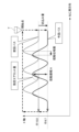
- 1 is a graph showing a positional relationship between a workpiece and a cutting tool.
- FIG. 11 is a functional block diagram of a display device of a machine tool according to a modified example.
- FIG. 1 is a functional block diagram of a machine tool control device 1 according to one embodiment of the present invention.
- the machine tool control device 1 according to one embodiment of the present invention is for performing thread cutting using a cutting tool that oscillates radially relative to a workpiece.
- FIG. 1 only shows a motor 3 that drives one feed axis.
- the cutting process according to this embodiment is not limited to a specific shape of the workpiece. In other words, it can be applied even when the workpiece has a tapered or arc-shaped portion on the machining surface, requiring multiple feed axes (Z axis and X axis), or when the workpiece is cylindrical or cylindrical and only one specific feed axis (Z axis) is sufficient.
- the machine tool control device 1 of this embodiment is configured, for example, using a computer equipped with memories such as ROM (read only memory) and RAM (random access memory), a CPU (control processing unit), and a communication control unit, all connected to each other via a bus.
- the functions and operations of each of the above functional units are achieved by the cooperation of the CPU and memory mounted on the computer, and the control program stored in the memory.
- the machine tool control device 1 may also be configured with a CNC (Computer Numerical Controller) or a PLC (Programmable Logic Controller), or may be connected to a higher-level computer that outputs machining conditions such as rotation speed in addition to machining programs.
- the machine tool control device 1 includes a condition acquisition unit 11, an air cut amount acquisition unit 12, a machining control unit 13, a memory unit 14, an input unit 15, and a display unit 16.
- the condition acquisition unit 11 acquires the machining conditions and oscillation conditions for oscillating the workpiece.
- the machining conditions and oscillation conditions may be, for example, those stored in the memory unit 14, or may be those output from an external computer.
- the machining conditions include at least information regarding the relative feed rate per revolution between the cutting tool and the workpiece, and information regarding the shape of the cutting tool cutting edge, as well as information regarding, for example, the spindle rotation speed S (1/min), the feed rate of the cutting tool (mm/min), the workpiece diameter (mm), the clearance angle of the cutting tool (°), etc.
- Examples of information regarding the relative feed rate per revolution between the cutting tool and the workpiece include the feed rate per revolution F (mm/rev) and a combination of the spindle rotation speed S (1/min) and the feed rate of the cutting tool (mm/min), and examples of information regarding the shape of the cutting tool cutting edge include the radius of the cutting edge (mm).
- the oscillation conditions include information related to the number of oscillations in the radial direction of the workpiece and information related to the oscillation amplitude in the radial direction of the workpiece.
- Information related to the number of oscillations in the radial direction of the workpiece includes the oscillation frequency multiplication factor I (times), which indicates the oscillation frequency per one rotation of the spindle.
- Information related to the oscillation amplitude in the radial direction of the workpiece relative to the cutting tool and workpiece includes the oscillation amplitude multiplication factor K (times), which indicates the magnitude of the oscillation amplitude relative to the amount of cutting depth in the radial direction of the workpiece in thread cutting.
- the air cut amount acquisition unit 12 acquires a specified air cut amount that is specified in advance by an operator or the like.
- the air cut amount may be, for example, stored in the memory unit 14, may be acquired from an external computer, or may be input via the input unit 15.
- the air cut amount referred to here is the air cut amount between the nth thread cutting pass and the thread cutting pass after the nth thread cutting pass (n+1 or later).
- the air cut amount between the nth thread cutting pass and the n+1th thread cutting pass is used to determine the machining conditions.
- the air cut amount between the nth thread cutting pass and the n+2th thread cutting pass may also be used to determine the machining conditions.
- the air cut amount is the distance in the oscillation direction.
- the workpiece oscillates in the radial direction, so the air cut amount is a numerical value that indicates the degree of air cut in the radial direction of the workpiece.
- the air cut amount only needs to be an index that indicates the magnitude of the air cut, and may be expressed as the distance in the oscillation direction, an area including the oscillation direction, a level linked to the air cut amount previously determined in a table, or a multiplication factor relative to an arbitrary reference value (such as the cutting depth).
- the machining control unit 13 controls machining based on the conditions acquired by the condition acquisition unit 11 so that the air cut amount after machining starts becomes the designated air cut amount. Details of machining control by the machining control unit 13 will be described later.
- the memory unit 14 stores various information for controlling and machining the machine tool.
- the memory unit 14 stores the machining conditions, oscillation conditions, and air cut amount specified by the operator.
- the machining conditions, oscillation conditions, and air cut amount are, for example, input by the operator into the machining program or specified as machine tool parameters.
- the memory unit 14 may be configured to be located outside the control device 1 instead of inside it.
- the input unit 15 inputs information related to processing in response to an operator's input operation on an input means (not shown), such as a keyboard or a touch panel.
- the information related to processing input by the input unit 15 is stored in the memory unit 10, etc., or input to each part of the control device 1.
- the display unit 16 displays various information related to the machine tool, the control device 1, and processing.
- FIG. 2 is a block diagram showing the conditions acquired by the condition acquisition unit 11 in this embodiment.
- the condition acquisition unit 11 includes a phase difference acquisition unit 21 and a cutting depth acquisition unit 22.
- the phase difference acquisition unit 21 acquires the oscillation phase difference set in the control device 1 of the machine tool as a condition for the thread cutting process.
- the cutting depth acquisition unit 22 acquires the cutting depth for the thread cutting process as a condition for the thread cutting process.
- FIG. 4 is a graph showing the positional relationship between the workpiece and the cutting tool T.
- the machining program shown in FIG. 3 is generated by specifying various information via the input unit 15, etc., by the operator.
- the graph in Figure 4 shows the positional relationship between the workpiece and the cutting tool T.
- the machining control unit 13 determines the oscillation amplitude so that the air cut amount between the previous pass, which is the nth cutting pass, and the current pass, which is the (n+1)th cutting pass, becomes the specified air cut amount.
- the oscillation amplitude is in the same direction as the X-axis direction, which is also the cutting direction of the workpiece.
- the "S1000 M03" block is a statement that indicates that the spindle is to rotate in the forward direction.
- the "G8.5 P3L0.02" block contains “L0.02", which indicates the specified air cut amount.
- the "G92 X10.0 Z10.00 F2.0” block and the “G92 X9.7 Z10.00 F2.0” block indicate the cutting depth from the difference in the X coordinate.
- the condition acquisition unit 11 of the control device 1 acquires the oscillation phase difference that is held as a setting of the control device 1 of the machine tool.
- a phase difference of 90 degrees is set in the control device 1.
- the condition acquisition unit 11 acquires the oscillation phase difference of 90 degrees.
- the condition acquisition unit 11 also acquires the cutting depth from the machining program.
- the air cut amount acquisition unit 12 also acquires the designated air cut amount.
- the air cut amount acquisition unit 12 acquires the designated air cut amount of 0.02 [mm] from "L0.02".
- the machining control unit 13 uses the following formula to determine the oscillation amplitude for thread cutting based on the oscillation phase difference and cutting depth amount, which are the conditions acquired by the condition acquisition unit 11, and the specified air cut amount acquired by the air cut amount acquisition unit 12.
- I represents the frequency multiplication factor [times]
- L represents the specified air cut amount [mm]
- A represents the oscillation amplitude [mm]
- ⁇ represents the phase of the workpiece [°] at which the air cut amount becomes L.
- the processing control unit 13 outputs information indicating the calculated oscillation amplitude to the display unit 16.
- the display unit 16 communicates the oscillation amplitude to the operator by text information, graphic information, or a combination thereof indicating the oscillation amplitude.
- the control device 1 for a machine tool that performs thread cutting using a cutting tool T that oscillates relative to a workpiece provides the following effects.
- the control device 1 of the machine tool includes a condition acquisition unit 11 that acquires one or two pieces of information as preconditions out of three pieces of information: the oscillation phase difference between the nth thread cutting pass and a thread cutting pass after the nth, information on the amount of cutting in the radial direction of the workpiece, and information on the oscillation amplitude in the radial direction of the workpiece; an air cut amount acquisition unit 12 that acquires a designated air cut amount indicating the degree of air cut in the oscillation direction; and a machining control unit 13 that determines the information among the three pieces of information that the condition acquisition unit 11 has not acquired based on preconditions so that the air cut amount based on the nth thread cutting pass and a thread cutting pass after the nth becomes the designated air cut amount, and performs machining control.
- a condition acquisition unit 11 that acquires one or two pieces of information as preconditions out of three pieces of information: the oscillation phase difference between the nth thread cutting pass and a thread cutting pass after the nth,
- the target designated air cut amount is set, it is possible to accurately determine whether chip shredding is possible even if the machining conditions change in thread cutting.
- the margin amount according to the designated air cut amount an appropriate air strike can be achieved even if the oscillation phase difference is not 180 degrees.
- the condition acquisition unit 11 acquires, as preconditions, the information on the oscillation phase difference and the cutting depth amount out of the three pieces of information, and the machining control unit 13 determines information on the oscillation amplitude based on the information on the oscillation phase difference and the cutting depth amount so that the air cut amount based on the gap between the nth thread cutting machining pass and any thread cutting machining pass after the nth thread cutting machining pass becomes the specified air cut amount.
- the control device 1 of this embodiment further includes a display unit 16 that outputs information determined by the processing control unit 13. This allows the operator to easily check safety and production plans based on the calculation results of the processing control unit 13, such as the oscillation amplitude.
- the machining control unit 13 calculates the oscillation amplitude, but it may be configured to determine the amplitude magnification instead of the oscillation amplitude.
- the amplitude is determined from the cutting depth in the radial direction of the workpiece in the thread cutting process and the amplitude magnification, and control is performed using that amplitude.
- the machining control unit may be configured to determine information different from the information on the oscillation amplitude depending on the conditions acquired by the condition acquisition unit.
- the condition acquisition unit may acquire information on the oscillation phase difference and the oscillation amplitude, and the machining control unit may determine information on the cutting amount based on the information on the oscillation phase difference and the oscillation amplitude.
- the condition acquisition unit may acquire the oscillation phase difference, information on the cutting amount, and specific information that identifies the information on the oscillation amplitude, and the machining control unit may determine information on the cutting amount and information on the oscillation amplitude based on the oscillation phase difference and the specific information.
- the condition acquisition unit may acquire information on the oscillation amplitude, information on the cutting amount, and specific information that identifies the oscillation phase difference, and the machining control unit may determine information on the cutting amount and the oscillation phase difference based on the information on the oscillation amplitude and the specific information.
- Specific numerical values can be calculated using, for example, formula (1).
- the above-mentioned specific information may be, for example, the upper limit of the specified oscillation amplitude, the upper speed limit, the upper acceleration limit, the upper jerk limit, etc.
- the oscillation amplitude can be uniquely identified by these and the oscillation frequency.
- the specific information is also set as a recommended value for the oscillation phase difference, and the oscillation phase difference can be uniquely determined even when the setting is to operate at the recommended value.
- the specific information is also set as an upper limit value for the amount of cutting in the radial direction of the workpiece, and if the amount of cutting in the radial direction of the workpiece is set to always be the upper limit value, the amount of cutting in the radial direction of the workpiece can be uniquely identified.
- a plurality of these exemplified pieces of specific information may be combined. In this way, the specific information is a rule set in the machine tool, and it is sufficient that the information is one that the machining control unit 13 can identify.
- the above-mentioned determination method and calculation method are merely examples, and the information required for processing control may be calculated using a method other than the method using the above-mentioned formula.
- the present disclosure is applied to a control device for a machine tool, but is not limited to this.
- the present disclosure may also be applied to a display device for a machine tool.
- FIG. 5 is a functional block diagram of the display device 9 of the machine tool according to the modified example.
- the display device 9 of the machine tool includes a condition input unit 91, an air cut amount input unit 92, an information calculation unit 93, and a display unit 96.
- the condition input unit 91 corresponds to the condition acquisition unit 11 in the above embodiment. That is, the condition input unit 91 accepts input of one or two pieces of information as preconditions out of three pieces of information: the oscillation phase difference between the nth thread cutting pass and a thread cutting pass after the nth thread cutting pass, information on the radial cutting depth of the workpiece, and information on the oscillation amplitude in the radial direction of the workpiece.
- the air cut amount input unit 92 corresponds to the air cut amount acquisition unit 12 in the above embodiment. That is, the air cut amount input unit 92 accepts input of a specified air cut amount that indicates the degree of air cut in the swing direction.
- the information calculation unit 93 corresponds to a part of the machining control unit 13 in the above embodiment. That is, the information calculation unit 93 calculates, based on preconditions, the information among the three pieces of information that is not accepted by the condition input unit, so that the air cut amount based on the gap between the nth thread cutting machining pass and the thread cutting machining pass after the nth thread cutting pass becomes the specified air cut amount.
- the display unit 96 corresponds to the display unit 16 in the above embodiment. That is, the display unit 96 displays the information calculated by the information calculation unit 93.
- the machine tool display device 9 having the above configuration provides the same effects as the machine tool control device 1 according to the above embodiment.
Landscapes
- Engineering & Computer Science (AREA)
- Mechanical Engineering (AREA)
- Human Computer Interaction (AREA)
- Manufacturing & Machinery (AREA)
- Physics & Mathematics (AREA)
- General Physics & Mathematics (AREA)
- Automation & Control Theory (AREA)
- Numerical Control (AREA)
- Automatic Control Of Machine Tools (AREA)
Priority Applications (5)
| Application Number | Priority Date | Filing Date | Title |
|---|---|---|---|
| US19/110,371 US20260084220A1 (en) | 2022-09-30 | 2022-09-30 | Machine tool control device and machine tool display device |
| CN202280099896.6A CN119855678A (zh) | 2022-09-30 | 2022-09-30 | 机床的控制装置以及机床的显示装置 |
| DE112022007567.8T DE112022007567T5 (de) | 2022-09-30 | 2022-09-30 | Werkzeugmaschinen-Steuerungsvorrichtung und Werkzeugmaschinen-Anzeigevorrichtung |
| PCT/JP2022/036755 WO2024069954A1 (ja) | 2022-09-30 | 2022-09-30 | 工作機械の制御装置及び工作機械の表示装置 |
| JP2024549042A JP7827878B2 (ja) | 2022-09-30 | 2022-09-30 | 工作機械の制御装置及び工作機械の表示装置 |
Applications Claiming Priority (1)
| Application Number | Priority Date | Filing Date | Title |
|---|---|---|---|
| PCT/JP2022/036755 WO2024069954A1 (ja) | 2022-09-30 | 2022-09-30 | 工作機械の制御装置及び工作機械の表示装置 |
Publications (1)
| Publication Number | Publication Date |
|---|---|
| WO2024069954A1 true WO2024069954A1 (ja) | 2024-04-04 |
Family
ID=90476686
Family Applications (1)
| Application Number | Title | Priority Date | Filing Date |
|---|---|---|---|
| PCT/JP2022/036755 Ceased WO2024069954A1 (ja) | 2022-09-30 | 2022-09-30 | 工作機械の制御装置及び工作機械の表示装置 |
Country Status (5)
| Country | Link |
|---|---|
| US (1) | US20260084220A1 (https=) |
| JP (1) | JP7827878B2 (https=) |
| CN (1) | CN119855678A (https=) |
| DE (1) | DE112022007567T5 (https=) |
| WO (1) | WO2024069954A1 (https=) |
Citations (8)
| Publication number | Priority date | Publication date | Assignee | Title |
|---|---|---|---|---|
| JPH10124127A (ja) * | 1996-10-16 | 1998-05-15 | Mori Seiki Co Ltd | Nc旋盤を用いたねじ切り装置及びその方法 |
| US20090107308A1 (en) * | 2007-10-16 | 2009-04-30 | Woody Bethany A | Methods and systems for chip breaking in turning applications using cnc toolpaths |
| JP2014523348A (ja) * | 2011-06-15 | 2014-09-11 | ザウアー ウルトラソニック ゲーエムベーハー | 工作機械、工作物の機械加工方法 |
| JP2020066119A (ja) * | 2018-10-26 | 2020-04-30 | シチズン時計株式会社 | 工作機械及び制御装置 |
| WO2021117526A1 (ja) * | 2019-12-10 | 2021-06-17 | シチズン時計株式会社 | 加工装置、加工方法および切削工具 |
| JP2021194721A (ja) * | 2020-06-10 | 2021-12-27 | シチズン時計株式会社 | 工作機械の制御装置および工作機械 |
| JP2022060273A (ja) * | 2018-02-27 | 2022-04-14 | ファナック株式会社 | 制御装置 |
| JP7158604B1 (ja) * | 2021-06-02 | 2022-10-21 | 三菱電機株式会社 | 数値制御装置、学習装置、推論装置、および数値制御方法 |
-
2022
- 2022-09-30 JP JP2024549042A patent/JP7827878B2/ja active Active
- 2022-09-30 DE DE112022007567.8T patent/DE112022007567T5/de active Pending
- 2022-09-30 US US19/110,371 patent/US20260084220A1/en active Pending
- 2022-09-30 CN CN202280099896.6A patent/CN119855678A/zh active Pending
- 2022-09-30 WO PCT/JP2022/036755 patent/WO2024069954A1/ja not_active Ceased
Patent Citations (8)
| Publication number | Priority date | Publication date | Assignee | Title |
|---|---|---|---|---|
| JPH10124127A (ja) * | 1996-10-16 | 1998-05-15 | Mori Seiki Co Ltd | Nc旋盤を用いたねじ切り装置及びその方法 |
| US20090107308A1 (en) * | 2007-10-16 | 2009-04-30 | Woody Bethany A | Methods and systems for chip breaking in turning applications using cnc toolpaths |
| JP2014523348A (ja) * | 2011-06-15 | 2014-09-11 | ザウアー ウルトラソニック ゲーエムベーハー | 工作機械、工作物の機械加工方法 |
| JP2022060273A (ja) * | 2018-02-27 | 2022-04-14 | ファナック株式会社 | 制御装置 |
| JP2020066119A (ja) * | 2018-10-26 | 2020-04-30 | シチズン時計株式会社 | 工作機械及び制御装置 |
| WO2021117526A1 (ja) * | 2019-12-10 | 2021-06-17 | シチズン時計株式会社 | 加工装置、加工方法および切削工具 |
| JP2021194721A (ja) * | 2020-06-10 | 2021-12-27 | シチズン時計株式会社 | 工作機械の制御装置および工作機械 |
| JP7158604B1 (ja) * | 2021-06-02 | 2022-10-21 | 三菱電機株式会社 | 数値制御装置、学習装置、推論装置、および数値制御方法 |
Also Published As
| Publication number | Publication date |
|---|---|
| CN119855678A (zh) | 2025-04-18 |
| DE112022007567T5 (de) | 2025-05-15 |
| JPWO2024069954A1 (https=) | 2024-04-04 |
| JP7827878B2 (ja) | 2026-03-10 |
| US20260084220A1 (en) | 2026-03-26 |
Similar Documents
| Publication | Publication Date | Title |
|---|---|---|
| JP7252426B1 (ja) | 工作機械の制御装置及び工作機械の表示装置 | |
| CN112912804B (zh) | 数控装置、机器学习装置及数控方法 | |
| US10423145B2 (en) | Numerical controller capable of changing machining condition in accordance with machining information | |
| US11474497B2 (en) | Numerical control device, machine learning device, and numerical control method | |
| US20100114359A1 (en) | Programming apparatus | |
| CN115104073B (zh) | 机床的控制装置 | |
| US20240272603A1 (en) | Information processing device, device for controlling machine tool, and non-transitory computer-readable medium storing a computer program | |
| US7058473B2 (en) | Method and device for generation of machining program | |
| CN109648387B (zh) | 控制装置 | |
| US20240131648A1 (en) | Machine tool control device | |
| JP4639058B2 (ja) | ねじ切り加工装置 | |
| WO2024062544A1 (ja) | 工作機械の表示装置 | |
| JP7827878B2 (ja) | 工作機械の制御装置及び工作機械の表示装置 | |
| US20230037816A1 (en) | Control device for machine tool | |
| EP0130218A1 (en) | Method of protecting file of numerical control | |
| WO2024116336A1 (ja) | 工作機械の制御装置 | |
| WO2023139743A1 (ja) | 情報処理装置、工作機械の制御装置、及びコンピュータプログラム | |
| CN117099061A (zh) | 信息处理装置及信息处理程序 | |
| JP7799048B2 (ja) | 工作機械の制御装置 | |
| JP7734865B1 (ja) | 数値制御装置 | |
| JPS61103207A (ja) | 数値制御システム | |
| WO2024232099A1 (ja) | 計算装置 | |
| WO2024105842A1 (ja) | 工作機械の制御装置 | |
| WO2024232103A1 (ja) | 工作機械の表示装置 | |
| WO2024232100A1 (ja) | 工作機械の表示装置、工作機械の制御装置及びプログラム |
Legal Events
| Date | Code | Title | Description |
|---|---|---|---|
| 121 | Ep: the epo has been informed by wipo that ep was designated in this application |
Ref document number: 22961013 Country of ref document: EP Kind code of ref document: A1 |
|
| WWE | Wipo information: entry into national phase |
Ref document number: 2024549042 Country of ref document: JP Ref document number: 202280099896.6 Country of ref document: CN |
|
| WWE | Wipo information: entry into national phase |
Ref document number: 112022007567 Country of ref document: DE |
|
| WWP | Wipo information: published in national office |
Ref document number: 202280099896.6 Country of ref document: CN |
|
| WWP | Wipo information: published in national office |
Ref document number: 112022007567 Country of ref document: DE |
|
| 122 | Ep: pct application non-entry in european phase |
Ref document number: 22961013 Country of ref document: EP Kind code of ref document: A1 |