WO2024062612A1 - Cutting tool - Google Patents
Cutting tool Download PDFInfo
- Publication number
- WO2024062612A1 WO2024062612A1 PCT/JP2022/035451 JP2022035451W WO2024062612A1 WO 2024062612 A1 WO2024062612 A1 WO 2024062612A1 JP 2022035451 W JP2022035451 W JP 2022035451W WO 2024062612 A1 WO2024062612 A1 WO 2024062612A1
- Authority
- WO
- WIPO (PCT)
- Prior art keywords
- layer
- unit
- unit layer
- less
- thickness
- Prior art date
Links
- 238000005520 cutting process Methods 0.000 title claims abstract description 292
- 239000011248 coating agent Substances 0.000 claims abstract description 108
- 238000000576 coating method Methods 0.000 claims abstract description 108
- 239000000203 mixture Substances 0.000 claims description 117
- 239000000463 material Substances 0.000 claims description 116
- 229910052796 boron Chemical group 0.000 claims description 10
- ZOXJGFHDIHLPTG-UHFFFAOYSA-N Boron Chemical group [B] ZOXJGFHDIHLPTG-UHFFFAOYSA-N 0.000 claims description 9
- 229910052710 silicon Inorganic materials 0.000 claims description 9
- 239000010703 silicon Substances 0.000 claims description 8
- 239000000758 substrate Substances 0.000 abstract description 9
- 239000010410 layer Substances 0.000 description 698
- 238000000034 method Methods 0.000 description 64
- 238000005259 measurement Methods 0.000 description 38
- 230000003647 oxidation Effects 0.000 description 29
- 238000007254 oxidation reaction Methods 0.000 description 29
- 239000010936 titanium Substances 0.000 description 22
- 125000004429 atom Chemical group 0.000 description 19
- 230000000694 effects Effects 0.000 description 17
- 239000007789 gas Substances 0.000 description 15
- 238000003801 milling Methods 0.000 description 15
- 238000012360 testing method Methods 0.000 description 14
- 239000012535 impurity Substances 0.000 description 12
- 239000013078 crystal Substances 0.000 description 11
- 238000003754 machining Methods 0.000 description 10
- 229910052782 aluminium Inorganic materials 0.000 description 9
- IJGRMHOSHXDMSA-UHFFFAOYSA-N Atomic nitrogen Chemical compound N#N IJGRMHOSHXDMSA-UHFFFAOYSA-N 0.000 description 8
- 238000004519 manufacturing process Methods 0.000 description 8
- 238000005240 physical vapour deposition Methods 0.000 description 8
- 238000007733 ion plating Methods 0.000 description 7
- 238000010030 laminating Methods 0.000 description 7
- 238000007514 turning Methods 0.000 description 7
- XKRFYHLGVUSROY-UHFFFAOYSA-N Argon Chemical compound [Ar] XKRFYHLGVUSROY-UHFFFAOYSA-N 0.000 description 6
- 229910052799 carbon Inorganic materials 0.000 description 6
- 229910052719 titanium Inorganic materials 0.000 description 6
- OKTJSMMVPCPJKN-UHFFFAOYSA-N Carbon Chemical compound [C] OKTJSMMVPCPJKN-UHFFFAOYSA-N 0.000 description 5
- 230000005540 biological transmission Effects 0.000 description 5
- 230000008020 evaporation Effects 0.000 description 5
- 238000001704 evaporation Methods 0.000 description 5
- 238000001755 magnetron sputter deposition Methods 0.000 description 5
- 229910052757 nitrogen Inorganic materials 0.000 description 5
- 229910052684 Cerium Inorganic materials 0.000 description 4
- QVGXLLKOCUKJST-UHFFFAOYSA-N atomic oxygen Chemical compound [O] QVGXLLKOCUKJST-UHFFFAOYSA-N 0.000 description 4
- 239000002826 coolant Substances 0.000 description 4
- 238000000921 elemental analysis Methods 0.000 description 4
- 238000011156 evaluation Methods 0.000 description 4
- 238000000691 measurement method Methods 0.000 description 4
- 229910021645 metal ion Inorganic materials 0.000 description 4
- VNWKTOKETHGBQD-UHFFFAOYSA-N methane Chemical compound C VNWKTOKETHGBQD-UHFFFAOYSA-N 0.000 description 4
- 229910052760 oxygen Inorganic materials 0.000 description 4
- 239000001301 oxygen Substances 0.000 description 4
- 238000012545 processing Methods 0.000 description 4
- ATJFFYVFTNAWJD-UHFFFAOYSA-N Tin Chemical compound [Sn] ATJFFYVFTNAWJD-UHFFFAOYSA-N 0.000 description 3
- 229910052786 argon Inorganic materials 0.000 description 3
- 239000011195 cermet Substances 0.000 description 3
- 238000011161 development Methods 0.000 description 3
- 238000010894 electron beam technology Methods 0.000 description 3
- 238000002149 energy-dispersive X-ray emission spectroscopy Methods 0.000 description 3
- 238000005516 engineering process Methods 0.000 description 3
- 238000009413 insulation Methods 0.000 description 3
- 229910052751 metal Inorganic materials 0.000 description 3
- 230000008569 process Effects 0.000 description 3
- 230000009467 reduction Effects 0.000 description 3
- 229910009043 WC-Co Inorganic materials 0.000 description 2
- 229910045601 alloy Inorganic materials 0.000 description 2
- 239000000956 alloy Substances 0.000 description 2
- 229910052810 boron oxide Inorganic materials 0.000 description 2
- 150000001875 compounds Chemical class 0.000 description 2
- 238000012937 correction Methods 0.000 description 2
- 230000007423 decrease Effects 0.000 description 2
- 238000000151 deposition Methods 0.000 description 2
- JKWMSGQKBLHBQQ-UHFFFAOYSA-N diboron trioxide Chemical compound O=BOB=O JKWMSGQKBLHBQQ-UHFFFAOYSA-N 0.000 description 2
- 238000009837 dry grinding Methods 0.000 description 2
- 230000007613 environmental effect Effects 0.000 description 2
- 238000003475 lamination Methods 0.000 description 2
- 239000000314 lubricant Substances 0.000 description 2
- 230000007246 mechanism Effects 0.000 description 2
- 230000008018 melting Effects 0.000 description 2
- 238000002844 melting Methods 0.000 description 2
- 239000002184 metal Substances 0.000 description 2
- 239000011812 mixed powder Substances 0.000 description 2
- 150000004767 nitrides Chemical class 0.000 description 2
- 239000000843 powder Substances 0.000 description 2
- 238000004663 powder metallurgy Methods 0.000 description 2
- 238000002360 preparation method Methods 0.000 description 2
- 239000002994 raw material Substances 0.000 description 2
- 239000012495 reaction gas Substances 0.000 description 2
- 239000000126 substance Substances 0.000 description 2
- 239000002344 surface layer Substances 0.000 description 2
- 238000012546 transfer Methods 0.000 description 2
- 238000004627 transmission electron microscopy Methods 0.000 description 2
- 229910052720 vanadium Inorganic materials 0.000 description 2
- 229910018072 Al 2 O 3 Inorganic materials 0.000 description 1
- 229910052582 BN Inorganic materials 0.000 description 1
- PZNSFCLAULLKQX-UHFFFAOYSA-N Boron nitride Chemical compound N#B PZNSFCLAULLKQX-UHFFFAOYSA-N 0.000 description 1
- 229910000997 High-speed steel Inorganic materials 0.000 description 1
- 229910052581 Si3N4 Inorganic materials 0.000 description 1
- 229910001069 Ti alloy Inorganic materials 0.000 description 1
- 238000002441 X-ray diffraction Methods 0.000 description 1
- 238000005299 abrasion Methods 0.000 description 1
- 230000004888 barrier function Effects 0.000 description 1
- 230000015572 biosynthetic process Effects 0.000 description 1
- 238000005422 blasting Methods 0.000 description 1
- 125000004432 carbon atom Chemical group C* 0.000 description 1
- 239000000919 ceramic Substances 0.000 description 1
- 238000006243 chemical reaction Methods 0.000 description 1
- 238000005229 chemical vapour deposition Methods 0.000 description 1
- PMHQVHHXPFUNSP-UHFFFAOYSA-M copper(1+);methylsulfanylmethane;bromide Chemical compound Br[Cu].CSC PMHQVHHXPFUNSP-UHFFFAOYSA-M 0.000 description 1
- 239000002173 cutting fluid Substances 0.000 description 1
- 238000013461 design Methods 0.000 description 1
- 238000010586 diagram Methods 0.000 description 1
- 229910003460 diamond Inorganic materials 0.000 description 1
- 239000010432 diamond Substances 0.000 description 1
- 238000001035 drying Methods 0.000 description 1
- 238000010891 electric arc Methods 0.000 description 1
- 238000000227 grinding Methods 0.000 description 1
- 229910000816 inconels 718 Inorganic materials 0.000 description 1
- 238000010849 ion bombardment Methods 0.000 description 1
- 150000002500 ions Chemical class 0.000 description 1
- 238000002156 mixing Methods 0.000 description 1
- 229910052758 niobium Inorganic materials 0.000 description 1
- TWNQGVIAIRXVLR-UHFFFAOYSA-N oxo(oxoalumanyloxy)alumane Chemical compound O=[Al]O[Al]=O TWNQGVIAIRXVLR-UHFFFAOYSA-N 0.000 description 1
- 230000009257 reactivity Effects 0.000 description 1
- HBMJWWWQQXIZIP-UHFFFAOYSA-N silicon carbide Chemical compound [Si+]#[C-] HBMJWWWQQXIZIP-UHFFFAOYSA-N 0.000 description 1
- 229910010271 silicon carbide Inorganic materials 0.000 description 1
- HQVNEWCFYHHQES-UHFFFAOYSA-N silicon nitride Chemical compound N12[Si]34N5[Si]62N3[Si]51N64 HQVNEWCFYHHQES-UHFFFAOYSA-N 0.000 description 1
- 238000001330 spinodal decomposition reaction Methods 0.000 description 1
- 238000004381 surface treatment Methods 0.000 description 1
- 229910052715 tantalum Inorganic materials 0.000 description 1
- MTPVUVINMAGMJL-UHFFFAOYSA-N trimethyl(1,1,2,2,2-pentafluoroethyl)silane Chemical compound C[Si](C)(C)C(F)(F)C(F)(F)F MTPVUVINMAGMJL-UHFFFAOYSA-N 0.000 description 1
- 239000002699 waste material Substances 0.000 description 1
Images


Classifications
-
- B—PERFORMING OPERATIONS; TRANSPORTING
- B23—MACHINE TOOLS; METAL-WORKING NOT OTHERWISE PROVIDED FOR
- B23B—TURNING; BORING
- B23B27/00—Tools for turning or boring machines; Tools of a similar kind in general; Accessories therefor
- B23B27/14—Cutting tools of which the bits or tips or cutting inserts are of special material
- B23B27/148—Composition of the cutting inserts
-
- B—PERFORMING OPERATIONS; TRANSPORTING
- B23—MACHINE TOOLS; METAL-WORKING NOT OTHERWISE PROVIDED FOR
- B23B—TURNING; BORING
- B23B27/00—Tools for turning or boring machines; Tools of a similar kind in general; Accessories therefor
- B23B27/14—Cutting tools of which the bits or tips or cutting inserts are of special material
-
- C—CHEMISTRY; METALLURGY
- C23—COATING METALLIC MATERIAL; COATING MATERIAL WITH METALLIC MATERIAL; CHEMICAL SURFACE TREATMENT; DIFFUSION TREATMENT OF METALLIC MATERIAL; COATING BY VACUUM EVAPORATION, BY SPUTTERING, BY ION IMPLANTATION OR BY CHEMICAL VAPOUR DEPOSITION, IN GENERAL; INHIBITING CORROSION OF METALLIC MATERIAL OR INCRUSTATION IN GENERAL
- C23C—COATING METALLIC MATERIAL; COATING MATERIAL WITH METALLIC MATERIAL; SURFACE TREATMENT OF METALLIC MATERIAL BY DIFFUSION INTO THE SURFACE, BY CHEMICAL CONVERSION OR SUBSTITUTION; COATING BY VACUUM EVAPORATION, BY SPUTTERING, BY ION IMPLANTATION OR BY CHEMICAL VAPOUR DEPOSITION, IN GENERAL
- C23C14/00—Coating by vacuum evaporation, by sputtering or by ion implantation of the coating forming material
- C23C14/06—Coating by vacuum evaporation, by sputtering or by ion implantation of the coating forming material characterised by the coating material
- C23C14/0641—Nitrides
- C23C14/0647—Boron nitride
-
- C—CHEMISTRY; METALLURGY
- C23—COATING METALLIC MATERIAL; COATING MATERIAL WITH METALLIC MATERIAL; CHEMICAL SURFACE TREATMENT; DIFFUSION TREATMENT OF METALLIC MATERIAL; COATING BY VACUUM EVAPORATION, BY SPUTTERING, BY ION IMPLANTATION OR BY CHEMICAL VAPOUR DEPOSITION, IN GENERAL; INHIBITING CORROSION OF METALLIC MATERIAL OR INCRUSTATION IN GENERAL
- C23C—COATING METALLIC MATERIAL; COATING MATERIAL WITH METALLIC MATERIAL; SURFACE TREATMENT OF METALLIC MATERIAL BY DIFFUSION INTO THE SURFACE, BY CHEMICAL CONVERSION OR SUBSTITUTION; COATING BY VACUUM EVAPORATION, BY SPUTTERING, BY ION IMPLANTATION OR BY CHEMICAL VAPOUR DEPOSITION, IN GENERAL
- C23C14/00—Coating by vacuum evaporation, by sputtering or by ion implantation of the coating forming material
- C23C14/06—Coating by vacuum evaporation, by sputtering or by ion implantation of the coating forming material characterised by the coating material
- C23C14/0641—Nitrides
- C23C14/0652—Silicon nitride
-
- C—CHEMISTRY; METALLURGY
- C23—COATING METALLIC MATERIAL; COATING MATERIAL WITH METALLIC MATERIAL; CHEMICAL SURFACE TREATMENT; DIFFUSION TREATMENT OF METALLIC MATERIAL; COATING BY VACUUM EVAPORATION, BY SPUTTERING, BY ION IMPLANTATION OR BY CHEMICAL VAPOUR DEPOSITION, IN GENERAL; INHIBITING CORROSION OF METALLIC MATERIAL OR INCRUSTATION IN GENERAL
- C23C—COATING METALLIC MATERIAL; COATING MATERIAL WITH METALLIC MATERIAL; SURFACE TREATMENT OF METALLIC MATERIAL BY DIFFUSION INTO THE SURFACE, BY CHEMICAL CONVERSION OR SUBSTITUTION; COATING BY VACUUM EVAPORATION, BY SPUTTERING, BY ION IMPLANTATION OR BY CHEMICAL VAPOUR DEPOSITION, IN GENERAL
- C23C14/00—Coating by vacuum evaporation, by sputtering or by ion implantation of the coating forming material
- C23C14/06—Coating by vacuum evaporation, by sputtering or by ion implantation of the coating forming material characterised by the coating material
- C23C14/0664—Carbonitrides
-
- C—CHEMISTRY; METALLURGY
- C23—COATING METALLIC MATERIAL; COATING MATERIAL WITH METALLIC MATERIAL; CHEMICAL SURFACE TREATMENT; DIFFUSION TREATMENT OF METALLIC MATERIAL; COATING BY VACUUM EVAPORATION, BY SPUTTERING, BY ION IMPLANTATION OR BY CHEMICAL VAPOUR DEPOSITION, IN GENERAL; INHIBITING CORROSION OF METALLIC MATERIAL OR INCRUSTATION IN GENERAL
- C23C—COATING METALLIC MATERIAL; COATING MATERIAL WITH METALLIC MATERIAL; SURFACE TREATMENT OF METALLIC MATERIAL BY DIFFUSION INTO THE SURFACE, BY CHEMICAL CONVERSION OR SUBSTITUTION; COATING BY VACUUM EVAPORATION, BY SPUTTERING, BY ION IMPLANTATION OR BY CHEMICAL VAPOUR DEPOSITION, IN GENERAL
- C23C14/00—Coating by vacuum evaporation, by sputtering or by ion implantation of the coating forming material
- C23C14/22—Coating by vacuum evaporation, by sputtering or by ion implantation of the coating forming material characterised by the process of coating
- C23C14/34—Sputtering
-
- C—CHEMISTRY; METALLURGY
- C23—COATING METALLIC MATERIAL; COATING MATERIAL WITH METALLIC MATERIAL; CHEMICAL SURFACE TREATMENT; DIFFUSION TREATMENT OF METALLIC MATERIAL; COATING BY VACUUM EVAPORATION, BY SPUTTERING, BY ION IMPLANTATION OR BY CHEMICAL VAPOUR DEPOSITION, IN GENERAL; INHIBITING CORROSION OF METALLIC MATERIAL OR INCRUSTATION IN GENERAL
- C23C—COATING METALLIC MATERIAL; COATING MATERIAL WITH METALLIC MATERIAL; SURFACE TREATMENT OF METALLIC MATERIAL BY DIFFUSION INTO THE SURFACE, BY CHEMICAL CONVERSION OR SUBSTITUTION; COATING BY VACUUM EVAPORATION, BY SPUTTERING, BY ION IMPLANTATION OR BY CHEMICAL VAPOUR DEPOSITION, IN GENERAL
- C23C16/00—Chemical coating by decomposition of gaseous compounds, without leaving reaction products of surface material in the coating, i.e. chemical vapour deposition [CVD] processes
- C23C16/22—Chemical coating by decomposition of gaseous compounds, without leaving reaction products of surface material in the coating, i.e. chemical vapour deposition [CVD] processes characterised by the deposition of inorganic material, other than metallic material
- C23C16/30—Deposition of compounds, mixtures or solid solutions, e.g. borides, carbides, nitrides
- C23C16/34—Nitrides
-
- C—CHEMISTRY; METALLURGY
- C23—COATING METALLIC MATERIAL; COATING MATERIAL WITH METALLIC MATERIAL; CHEMICAL SURFACE TREATMENT; DIFFUSION TREATMENT OF METALLIC MATERIAL; COATING BY VACUUM EVAPORATION, BY SPUTTERING, BY ION IMPLANTATION OR BY CHEMICAL VAPOUR DEPOSITION, IN GENERAL; INHIBITING CORROSION OF METALLIC MATERIAL OR INCRUSTATION IN GENERAL
- C23C—COATING METALLIC MATERIAL; COATING MATERIAL WITH METALLIC MATERIAL; SURFACE TREATMENT OF METALLIC MATERIAL BY DIFFUSION INTO THE SURFACE, BY CHEMICAL CONVERSION OR SUBSTITUTION; COATING BY VACUUM EVAPORATION, BY SPUTTERING, BY ION IMPLANTATION OR BY CHEMICAL VAPOUR DEPOSITION, IN GENERAL
- C23C16/00—Chemical coating by decomposition of gaseous compounds, without leaving reaction products of surface material in the coating, i.e. chemical vapour deposition [CVD] processes
- C23C16/22—Chemical coating by decomposition of gaseous compounds, without leaving reaction products of surface material in the coating, i.e. chemical vapour deposition [CVD] processes characterised by the deposition of inorganic material, other than metallic material
- C23C16/30—Deposition of compounds, mixtures or solid solutions, e.g. borides, carbides, nitrides
- C23C16/36—Carbonitrides
-
- B—PERFORMING OPERATIONS; TRANSPORTING
- B23—MACHINE TOOLS; METAL-WORKING NOT OTHERWISE PROVIDED FOR
- B23B—TURNING; BORING
- B23B2228/00—Properties of materials of tools or workpieces, materials of tools or workpieces applied in a specific manner
- B23B2228/10—Coatings
- B23B2228/105—Coatings with specified thickness
Definitions
- the present disclosure relates to cutting tools.
- Patent Document 1 Conventionally, cutting tools comprising a base material and a coating disposed on the base material have been used for cutting (Patent Document 1 and Patent Document 2).
- a cutting tool includes a base material and a coating disposed on the base material,
- the coating includes a first layer;
- the first layer consists of alternating layers in which first unit layers and second unit layers are alternately laminated,
- the first unit layer is made of Ti 1-ab Al a Ce b N,
- the a is 0.350 or more and 0.650 or less
- the b is 0.001 or more and 0.100 or less
- the second unit layer is made of Al c V 1-c N,
- the c is 0.40 or more and 0.75 or less,
- the a and the c satisfy the relationship c>a.
- a cutting tool includes a base material and a coating disposed on the base material,
- the coating includes a first A layer,
- the first A layer consists of alternating layers in which first unit layers and third unit layers are alternately laminated,
- the first unit layer is made of Ti 1-ab Al a Ce b N,
- the a is 0.350 or more and 0.650 or less
- the b is 0.001 or more and 0.100 or less
- the third unit layer is made of Al d V 1-de M e N,
- the M is silicon or boron
- the d is 0.40 or more and 0.75 or less
- the e is greater than 0 and less than or equal to 0.05,
- the a and the d satisfy the relationship d>a.
- FIG. 1 is a schematic enlarged sectional view of a cutting tool according to an embodiment of the present disclosure.
- FIG. 2 is a schematic enlarged sectional view of a cutting tool according to another embodiment of the present disclosure.
- FIG. 3 is a schematic enlarged cross-sectional view of a cutting tool according to another embodiment of the present disclosure.
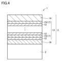
- FIG. 4 is a schematic enlarged sectional view of a cutting tool according to yet another embodiment of the present disclosure.
- FIG. 5 is a diagram for explaining an example of the ratio of the thicknesses of the first unit layer and the second unit layer.
- FIG. 6 is a schematic cross-sectional view of the cathode arc ion plating apparatus used in the example.
- FIG. 7 is a schematic top view of the cathode arc ion plating apparatus shown in FIG. 6.
- Patent Document 1 and Patent Document 2 Conventionally, as a coating tool material, a nitride or carbonitride film containing Ti and Al as main components has been coated on the surface of a base material (Patent Document 1 and Patent Document 2).
- a nitride or carbonitride film containing Ti and Al as main components has been coated on the surface of a base material (Patent Document 1 and Patent Document 2).
- cutting speeds are becoming faster due to dry machining that does not use cutting fluids and improving machining efficiency, and work materials are becoming more diverse.
- the cutting of heat-resistant alloys, titanium alloys, etc., which are difficult-to-cut materials is increasing, and for this reason, the temperature of the cutting tool tip during the cutting process tends to be high. That is, when the cutting edge temperature becomes high, the life of the cutting tool becomes extremely short. Therefore, there is a need for cutting tools that can exhibit excellent tool life even under such severe cutting conditions.
- a cutting tool includes a base material and a coating disposed on the base material,
- the coating includes a first layer;
- the first layer consists of alternating layers in which first unit layers and second unit layers are alternately laminated,
- the first unit layer is made of Ti 1-ab Al a Ce b N,
- the a is 0.350 or more and 0.650 or less
- the b is 0.001 or more and 0.100 or less
- the second unit layer is made of Al c V 1-c N,
- the c is 0.40 or more and 0.75 or less, The above a and the above c satisfy the relationship c>a.
- the ratio ⁇ 2/ ⁇ 1 of the thickness ⁇ 2 of the second unit layer to the thickness ⁇ 1 of the first unit layer in the first unit layer and the second unit layer adjacent to the first unit layer is 1 or more and 5 or less. This makes it possible to provide a cutting tool with a longer tool life, especially in cutting processing performed under conditions of high cutting edge temperatures.
- the average thickness of the first unit layer is 0.002 ⁇ m or more and 0.2 ⁇ m or less
- the average thickness of the second unit layer is preferably 0.002 ⁇ m or more and 0.2 ⁇ m or less. This makes it possible to provide a cutting tool that has a longer tool life, especially in cutting operations performed under conditions where the cutting edge temperature is high.
- the coating further includes a second layer disposed between the base material and the first layer,
- the composition of the second layer is preferably the same as the composition of the first unit layer or the composition of the second unit layer. This makes it possible to provide a cutting tool that has a longer tool life, especially in cutting operations performed under conditions where the cutting edge temperature is high.
- the composition of the second layer is the same as the composition of the first unit layer,
- the thickness of the second layer is preferably thicker than the thickness of the first unit layer. This makes it possible to provide a cutting tool that has a longer tool life, especially in cutting operations performed under conditions where the cutting edge temperature is high.
- the composition of the second layer is the same as the composition of the second unit layer,
- the thickness of the second layer is preferably thicker than the thickness of the second unit layer. This makes it possible to provide a cutting tool that has a longer tool life, especially in cutting operations performed under conditions where the cutting edge temperature is high.
- the coating further includes a third layer provided on the opposite side of the first layer to the base material,
- the third layer is made of TiAlCeCN. This makes it possible to provide a cutting tool that has a longer tool life, especially in cutting operations performed under conditions where the cutting edge temperature is high.
- a cutting tool includes a base material and a coating disposed on the base material,
- the coating includes a first A layer,
- the first A layer is composed of alternating layers in which first unit layers and third unit layers are alternately laminated,
- the first unit layer is made of Ti 1-ab Al a Ce b N,
- the a is 0.350 or more and 0.650 or less
- the b is 0.001 or more and 0.100 or less
- the third unit layer is made of Al d V 1-de M e N,
- the M is silicon or boron
- the d is 0.40 or more and 0.75 or less
- the e is greater than 0 and less than or equal to 0.05,
- the above a and the above d satisfy the relationship d>a.
- the thickness ⁇ 3 of the third unit layer is relative to the thickness ⁇ 1 of the first unit layer.
- the ratio ⁇ 3/ ⁇ 1 is preferably 1 or more and 5 or less. This makes it possible to provide a cutting tool that has a longer tool life, especially in cutting operations performed under conditions where the cutting edge temperature is high.
- the M is preferably silicon. This makes it possible to provide a cutting tool that has a longer tool life, especially in cutting operations performed under conditions where the cutting edge temperature is high.
- the M is preferably boron. This makes it possible to provide a cutting tool that has a longer tool life, especially in cutting operations performed under conditions where the cutting edge temperature is high.
- the average thickness of the first unit layer is 0.002 ⁇ m or more and 0.2 ⁇ m or less
- the average thickness of the third unit layer is preferably 0.002 ⁇ m or more and 0.2 ⁇ m or less. This makes it possible to provide a cutting tool that has a longer tool life, especially in cutting operations performed under conditions where the cutting edge temperature is high.
- the coating further includes a second layer disposed between the substrate and the first A layer,
- the composition of the second layer is preferably the same as the composition of the first unit layer or the composition of the third unit layer, which makes it possible to provide a cutting tool having a longer tool life, particularly in cutting processing performed under conditions of high cutting edge temperature.
- the composition of the second layer is the same as the composition of the first unit layer,
- the thickness of the second layer is preferably thicker than the thickness of the first unit layer. This makes it possible to provide a cutting tool that has a longer tool life, especially in cutting operations performed under conditions where the cutting edge temperature is high.
- the composition of the second layer is the same as the composition of the third unit layer,
- the thickness of the second layer is preferably greater than the thickness of the third unit layer, which makes it possible to provide a cutting tool having a longer tool life, particularly in cutting processing performed under conditions of high cutting edge temperature.
- the coating further includes a third layer provided on the side opposite to the base material of the first A layer, Preferably, the third layer is made of TiAlCeCN. This makes it possible to provide a cutting tool that has a longer tool life, especially in cutting operations performed under conditions where the cutting edge temperature is high.
- the notation in the format "A to B” means the upper and lower limits of the range (i.e., from A to B), and when there is no unit described in A and only in B, The units of and the units of B are the same.
- the atomic ratio when a compound or the like is expressed by a chemical formula, unless the atomic ratio is specifically limited, it includes all conventionally known atomic ratios, and should not necessarily be limited to only those in the stoichiometric range.
- TiAlCeN when "TiAlCeN" is written, the ratio of the number of atoms constituting TiAlCeN includes all conventionally known atomic ratios.
- FIGS. 1 to 5 A cutting tool according to an embodiment of the present disclosure will be described using FIGS. 1 to 5.
- An embodiment of the present disclosure (hereinafter also referred to as "Embodiment 1") includes: A cutting tool 1 comprising a base material 2 and a coating 3 disposed on the base material 2, The coating 3 includes a first layer 13, 13', The first layers 13, 13' are composed of alternating layers in which first unit layers 12 and second unit layers 15 are alternately laminated, The first unit layer 12 is made of Ti 1-ab Al a Ce b N, The a is 0.350 or more and 0.650 or less, The b is 0.001 or more and 0.100 or less, The second unit layer 15 is made of Al c V 1-c N, The c is 0.40 or more and 0.75 or less, The a and the c satisfy the relationship c>a.
- the coating 3 includes a first layer 13, 13', which is made up of alternating layers of first unit layers 12 and second unit layers 15 stacked alternately. This reduces the number of grain boundaries in the first layer, improving the "crack resistance” and “oxidation resistance” of the first layer 13, 13', and suppressing the "progression of cracks" at the interface between the first unit layer 12 and the second unit layer 15.
- the coating 3 includes the first layers 13, 13', and the first layers 13, 13' are composed of alternating layers in which the first unit layers 12 and the second unit layers 15 are alternately laminated. Consists of layers.
- the first unit layer 12 is made of Ti 1-ab Al a Ce b N
- the second unit layer 15 is made of Al c V 1-c N.
- Ti 1-ab Al a Ce b N is less susceptible to spinodal decomposition at high temperatures than Al c V 1-c N. Therefore, in the first unit layer 12, reduction in hardness is suppressed, compressive residual stress increases, and chipping resistance tends to be excellent.
- Al c V 1-c N has a smaller compressive residual stress than Ti 1-ab Al a Ce b N, and has excellent "thermal insulation” (in other words, "heat resistance”).
- thermo insulation in other words, "heat resistance”
- the melting point of V 2 O 5 which is an oxide of V, is 690°C, and since V 2 O 5 softens at the temperature during cutting and acts as a lubricant, it is necessary to reduce the coefficient of friction, especially on the rake face. can.
- the first layer 13, 13' is formed by alternately laminating the first unit layer 12 and the second unit layer 15, so that the first unit layer 12 has high "hardness" and the second unit layer
- the small compressive residual stress of the second unit layer 15 is complemented by the large compressive residual stress of the first unit layer 12. Therefore, the hardness, heat resistance, and compressive residual stress of the first layer 13, 13' as a whole can be improved in a well-balanced manner.
- the first unit layer 12 is made of Ti 1-ab Al a Ce b N, a is 0.350 or more and 0.650 or less, and b is It is 0.001 or more and 0.100 or less.
- Al is easily oxidized, a dense oxide layer made of Al 2 O 3 is easily formed on the surface side of the first unit layer 12 .
- Ce has a smaller standard energy of oxide formation than Al, it is more easily oxidized than Al, and a dense oxide layer made of CeO 2 is formed on the outermost surface of the first unit layer 12. easy. These oxide layers improve the "oxidation resistance" of the coating 3, suppress reactivity with the work material, and reduce the coefficient of friction with the work material.
- the lattice constant of CeN is 5.01 ⁇ , which is larger than the lattice constant of TiN, 4.23 ⁇ , and the lattice constant of AlN, 4.12 ⁇ , strain is introduced into the first unit layer 12. 12 tissues become finer. As a result, the first unit layer 12 has a high hardness, so that the "abrasion resistance" of the first unit layer 12 can be improved.
- the first unit layer 12 is made of Ti 1-ab Al a Ce b N
- the second unit layer 15 is made of Al c V 1-c N. ...
- the a and the c satisfy the relationship c>a. This is because the difference between the lattice constant of AlN and the lattice constant of VN in the second unit layer 15 is smaller than the difference between the lattice constant of TiN and the lattice constant of AlN in the first unit layer 12.
- the second unit layer 15 tends to have a higher Al content than the first unit layer 12. Therefore, by increasing the Al content in the second unit layer 15, the Al content contained in the entire first layer 13, 13' can be increased. As a result, the "heat resistance" and "oxidation resistance” of the first layers 13, 13' can be improved.
- the cutting tool 1 has excellent "crack resistance”, excellent “oxidation resistance”, excellent “crack growth suppressing effect”, high “hardness”, and excellent “wear resistance”. , and excellent “heat resistance”, it is possible to provide a cutting tool 1 that has a long tool life, especially in cutting operations performed under conditions where the cutting edge temperature is high.
- a cutting tool 1 includes a base material 2 and a coating 3 disposed on the base material 2.
- the film 3 preferably covers the entire surface of the base material 2, but even if a part of the base material 2 is not covered with the film 3 or the structure of the film 3 is partially different, the present invention will not apply. It does not depart from the scope of the embodiments.
- the coating 3 is preferably disposed so as to cover at least the surface of the portion of the base material 2 that is involved in cutting.
- the part involved in cutting of the base material 2 refers to the ridgeline of the cutting edge of the base material 2, and the part from the ridgeline of the cutting edge to the side of the base material 2, although it depends on the size and shape of the substrate 2. It means a region surrounded by an imaginary plane in which the distance along the perpendicular line to the tangent to the edge of the blade is, for example, 5 mm, 3 mm, 2 mm, 1 mm, or 0.5 mm.
- the cutting tool 1 of this embodiment includes a drill, an end mill, an indexable cutting tip for a drill, an indexable cutting tip for an end mill, an indexable cutting tip for milling, an indexable cutting tip for turning, a metal saw, and a tooth. It can be suitably used as a cutting tool 1 such as a cutting tool, a reamer, or a tap.
- any conventionally known base material 2 of this type can be used.
- cemented carbide WC-based cemented carbide, cemented carbide containing WC and Co, cemented carbide containing carbonitrides such as Ti, Ta, Nb, etc.
- cermet TiC, TiN, TiCN, etc.
- the main component shall be high-speed steel, ceramics (titanium carbide, silicon carbide, silicon nitride, aluminum nitride, aluminum oxide, etc.), cubic boron nitride sintered body, or diamond sintered body. is preferred.
- WC-based cemented carbide and cermet particularly TiCN-based cermet.
- These base materials 2 have an excellent balance between hardness and strength, especially at high temperatures, so when used as the base material 2 of the cutting tool 1, they can contribute to extending the life of the cutting tool 1.
- the coating 3 of Embodiment 1 includes first layers 13, 13'. By covering the base material 2, the coating 3 has the effect of improving various properties of the cutting tool 1, such as wear resistance and chipping resistance, and extending the life of the cutting tool 1. Note that, in addition to the first layers 13 and 13', the coating 3 can include "other layers" described later.
- the coating 3 preferably has a total thickness of 0.5 ⁇ m or more and 15 ⁇ m or less. If the total thickness is less than 0.5 ⁇ m, the thickness of the coating 3 is too thin, and the life of the cutting tool 1 tends to be shortened. On the other hand, if the total thickness is more than 15 ⁇ m, the coating 3 tends to chip at the initial stage of cutting, and the life of the cutting tool 1 tends to be shortened.
- the total thickness of the coating 3 can be measured by observing a cross section of the coating 3 using a scanning electron microscope (SEM).
- the observation magnification of the cross-sectional sample is set to 5,000 to 10,000 times, the observation area is set to 100 to 500 ⁇ m 2 , the thickness width is measured at three locations in one field of view, and the average value is defined as the “thickness”.
- the thickness of each layer described below is also the same unless otherwise specified.
- the absolute value of the compressive residual stress of the coating 3 is preferably 6 GPa or less.
- the compressive residual stress of the coating 3 is a type of internal stress (specific strain) that exists in the entire coating 3, and is expressed as a "-" (minus) numerical value (unit: "GPa” is used in this embodiment). This refers to the stress caused by Therefore, the concept that the compressive residual stress is large indicates that the absolute value of a numerical value becomes large, and the concept that the compressive residual stress is small indicates that the absolute value of a numerical value becomes small. That is, the absolute value of the compressive residual stress of 6 GPa or less means that the preferable compressive residual stress of the coating 3 is ⁇ 6 GPa or more and 0 GPa or less.
- the compressive residual stress of the coating 3 exceeds 0 GPa, it becomes tensile stress, so it tends to be difficult to suppress the propagation of cracks generated from the outermost surface of the coating 3.
- the absolute value of the compressive residual stress exceeds 6 GPa, the stress is too large, and the coating 3 may peel off, especially from the edge portion of the cutting tool 1, before cutting starts, which may shorten the life of the cutting tool 1. .
- the compressive residual stress of the coating 3 is measured by the sin2 ⁇ method (see pages 54 to 66 of "X-ray stress measurement method" (Japan Society of Materials Science, published by Yokendo Co., Ltd., 1981)) using an X-ray residual stress device. be able to.
- the crystal structure of the coating 3 is preferably cubic.
- the crystal structure of the coating 3 is cubic, the hardness of the coating 3 is improved. Therefore, it is preferable that each layer in the coating 3 has a cubic crystal structure. Note that the crystal structure of the coating 3 and each layer in the coating 3 can be analyzed using an X-ray diffraction apparatus known in the art.
- the hardness of the coating 3 is preferably 30 GPa or more and 55 GPa or less, more preferably 35 GPa or more and 50 GPa or less. According to this, the coating 3 has sufficient hardness.
- the hardness of the entire coating 3 can be measured by the nanoindenter method (Nano Indenter XP manufactured by MTS). Specifically, the hardness is measured at three locations on the surface of the coating 3 under a measurement load of 10 mN (1 gf), and the average value is defined as the "hardness".
- the first layers 13, 13' of this embodiment are composed of alternating layers in which first unit layers 12 and second unit layers 15 are alternately laminated. As a result, it is possible to improve the "crack resistance” and “oxidation resistance” of the first layers 13, 13', and the “propagation of cracks” at the interface between the first unit layer 12 and the second unit layer 15 is improved. ”, the “crack resistance” and “oxidation resistance” of the coating 3 can be improved, and the “propagation of cracks” in the coating 3 can be suppressed.
- the first layers 13, 13' are composed of alternating layers in which the first unit layer 12 and the second unit layer 15 are alternately laminated
- the cross section of the coating 3 is examined using a TEM (transmission electron microscope). This can be confirmed by observing the difference in contrast.
- the thickness of the first layer 13, 13' is preferably 0.5 ⁇ m or more and 15 ⁇ m or less. If the thickness of the first layer 13, 13' is less than 0.5 ⁇ m, it tends to be unable to exhibit sufficient wear resistance in continuous machining, and if it exceeds 15 ⁇ m, it tends to be difficult to stabilize chipping resistance in interrupted cutting. There is.
- the thickness of the first layer 13, 13' can be determined by observing and measuring the cross section of the coating 3 using a TEM (transmission electron microscope). Specifically, the thin sample is irradiated with an electron beam, the electrons that have passed through the sample and the scattered electrons are imaged, observed at high magnification, and the thickness of the first layers 13, 13' can be measured. can.
- TEM transmission electron microscope
- the first unit layer 12 is made of Ti 1-a-b Al a Ce b N, where a is 0.350 or more and 0.650 or less, and b is 0.001 or more and 0.100 or less. This can improve the "oxidation resistance" and "wear resistance" of the coating 3.
- the a is preferably 0.400 or more, more preferably 0.450 or more, and even more preferably 0.500 or more.
- the a is preferably 0.650 or less, more preferably 0.600 or less, and even more preferably 0.550 or less.
- the a is preferably 0.400 or more and 0.650 or less, more preferably 0.450 or more and 0.600 or less, and even more preferably 0.500 or more and 0.055 or less.
- the b is preferably 0.005 or more, more preferably 0.01 or more, and even more preferably 0.015 or more.
- the b is preferably 0.070 or less, more preferably 0.050 or less, and even more preferably 0.020 or less.
- the b is preferably 0.005 or more and 0.050 or less, more preferably 0.007 or more and 0.030 or less, and even more preferably 0.010 or more and 0.020 or less.
- atomic % means the ratio (%) of the number of atoms to the total number of atoms constituting the layer. The ratio (%) of the number of atoms to the total number of atoms constituting the layer is obtained by the same method as the "measurement method of a and b" described later. It has been confirmed that as long as the measurements are performed using the same cutting tool 1, there is no variation in the measurement results even if the measurement locations are arbitrarily selected.
- the above a and b are determined by elemental analysis by transmission electron microscopy (TEM) observation of a cross section of the sample. Specifically, using the EDS (Energy Dispersive It can be determined by performing elemental analysis. It has been confirmed that as long as the same cutting tool 1 is used for measurement, there is no variation in the measurement results even if the measurement location is arbitrarily selected.
- EDS Electronicgy Dispersive It can be determined by performing elemental analysis. It has been confirmed that as long as the same cutting tool 1 is used for measurement, there is no variation in the measurement results even if the measurement location is arbitrarily selected.
- the second unit layer 15 is made of Al c V 1-c N. Due to this, AlVN has an excellent balance of heat barrier properties (in other words, "heat resistance”), “oxidation resistance”, and “toughness”, so the coating 3 has excellent “heat resistance” and excellent It can have both "oxidation resistance” and excellent “toughness”. Note that "consisting of Al c V 1-c N” means that inevitable impurities can be included in addition to Al c V 1-c N as long as the effects of the present disclosure are exhibited. Examples of the unavoidable impurities include oxygen and carbon.
- the total content of unavoidable impurities in the second unit layer 15 is preferably greater than 0 atomic % and less than 1 atomic %.
- atomic % means the ratio (%) of the number of atoms to the total number of atoms constituting the layer.
- the ratio (%) of the number of atoms to the total number of atoms constituting the layer is determined by the same method as the above-mentioned "method for measuring a and b". It has been confirmed that as long as the same cutting tool 1 is used for measurement, there is no variation in the measurement results even if the measurement location is arbitrarily selected.
- the c is 0.40 or more and 0.75 or less.
- the second unit layer 15 has a cubic crystal structure, which increases the hardness of the second unit layer 15, and as a result, the "wear resistance" of the second unit layer 15 improves.
- the c is preferably 0.50 or more, more preferably 0.55 or more, and even more preferably 0.60 or more.
- the c is preferably 0.75 or less, more preferably 0.70 or less, and even more preferably 0.65 or less.
- the c is preferably 0.50 or more and 0.75 or less, more preferably 0.55 or more and 0.70 or less, and even more preferably 0.60 or more and 0.65 or less.
- the above c is obtained by the same method as the measurement methods for the above a and b. It has been confirmed that there is no variation in the measurement results even if the measurement points are arbitrarily selected, so long as the measurement is performed using the same cutting tool 1.
- the average thickness of the first unit layer 12 is preferably 0.002 ⁇ m or more and 0.2 ⁇ m or less, and the average thickness of the second unit layer 15 is preferably 0.002 ⁇ m or more and 0.2 ⁇ m or less. According to this, the growth of cracks generated on the surface of the coating 3 can be further suppressed.
- the lower limit of the average thickness of the first unit layer 12 is preferably 0.002 ⁇ m or more, more preferably 0.005 ⁇ m or more, and even more preferably 0.01 ⁇ m or more.
- the upper limit of the average thickness of the first unit layer 12 is preferably 0.2 ⁇ m or less, more preferably 0.15 ⁇ m or less, and even more preferably 0.1 ⁇ m or less.
- the average thickness of the first unit layer 12 is more preferably 0.005 ⁇ m or more and 0.15 ⁇ m or less, and even more preferably 0.01 ⁇ m or more and 0.1 ⁇ m or less.
- the lower limit of the average thickness of the second unit layer 15 is preferably 0.002 ⁇ m or more, more preferably 0.005 ⁇ m or more, and even more preferably 0.01 ⁇ m or more.
- the upper limit of the average thickness of the second unit layer 15 is preferably 0.2 ⁇ m or less, more preferably 0.15 ⁇ m or less, and even more preferably 0.1 ⁇ m or less.
- the average thickness of the second unit layer 15 is more preferably 0.005 ⁇ m or more and 0.15 ⁇ m or less, and even more preferably 0.01 ⁇ m or more and 0.1 ⁇ m or less.
- the average thickness of the first unit layer 12 and the average thickness of the second unit layer 15 can be determined by the same method as the method for measuring the thickness of the first layers 13, 13'.
- the ratio ⁇ 2/ ⁇ 1 of the thickness ⁇ 2 of the second unit layer 15 to the thickness ⁇ 1 of the first unit layer 12 is ⁇ 2/ ⁇ 1.
- , is preferably 1 or more and 5 or less (FIG. 5). Since the "thermal conductivity" of the second unit layer 15 is low, the second unit layer 15 has a property that it is difficult to transfer heat generated during cutting to the base material 2.
- ⁇ 2/ ⁇ 1 is preferably 1 or more, more preferably 1.5 or more, and even more preferably 2 or more.
- ⁇ 2/ ⁇ 1 is preferably 5 or less, more preferably 4 or less, and even more preferably 3 or less.
- ⁇ 2/ ⁇ 1 is preferably 1 or more and 5 or less, more preferably 1.5 or more and 4 or less, and even more preferably 2 or more and 3 or less.
- the number of stacked layers of each of the first unit layer 12 and the second unit layer 15 is preferably 10 or more and 500 or less. According to this, there is a tendency to easily obtain "the effect of improving hardness and compressive residual stress in a well-balanced manner by laminating the first unit layer 12 and the second unit layer 15."
- the number of stacked layers of each of the first unit layer 12 and the second unit layer 15 is more preferably 100 or more and 400 or less, and even more preferably 200 or more and 350 or less.
- the number of stacked layers of the first unit layer 12 and the second unit layer 15 is determined by observing and measuring the cross section of the coating 3 using a TEM (transmission electron microscope). You can ask for it. Specifically, a thin sample is irradiated with an electron beam, the electrons that have passed through the sample and the scattered electrons are imaged, and observed at high magnification. The number of laminated layers can be measured.
- TEM transmission electron microscope
- the coating 3 further includes a second layer 16 disposed between the substrate 2 and the first layer 13, 13', and the composition of the second layer 16 is preferably the same as the composition of the first unit layer 12 or the composition of the second unit layer 15 (FIGS. 3 and 4). This can increase the adhesion between the substrate 2 and the coating 3.
- composition of the second layer 16 is the same as that of the first unit layer 12, even if the base material 2 is exposed at the initial stage of cutting, oxidation from the interface between the base material 2 and the coating 3 is prevented. Can be suppressed.
- the thickness of the second layer 16 is preferably thicker than the thickness of the first unit layer 12.
- the adhesion between the base material 2 and the coating 3 can be further improved.
- the base material 2 is exposed at the initial stage of cutting, oxidation from the interface between the base material 2 and the coating 3 can be further suppressed.
- the thickness of the second layer 16 is thicker than the thickness of the first unit layer 12
- the thickness of the second layer 16 is more than 1.0 times the thickness of the first unit layer 12". It can be rephrased as ⁇ .
- the thickness of the second layer 16 is preferably 2.0 times or more, more preferably 4.0 times or more, and 10.0 times or more the thickness of the first unit layer 12. More preferred.
- the thickness of the second layer 16 is preferably 200 times or less than the thickness of the first unit layer 12, more preferably 120 times or less, and even more preferably 50 times or less.
- the thickness of the second layer 16 is preferably 2.0 times or more and 200 times or less, more preferably 4.0 times or more and 120 times or less, and 10.0 times the thickness of the first unit layer 12. It is more preferably at least 50 times.
- the thickness of the second layer 16 is preferably 0.1 ⁇ m or more. If the thickness of the second layer 16 is less than 0.1 ⁇ m, it is difficult to obtain the effect of suppressing oxidation from the interface between the base material 2 and the coating 3 by making the second layer 16 have the same composition as the first unit layer 12. There is a tendency.
- the thickness of the second layer 16 is more preferably 0.3 ⁇ m or more, and even more preferably 0.4 ⁇ m or more.
- the upper limit of the thickness of the second layer 16 is not particularly limited, but if it exceeds 2 ⁇ m, crystal grains become enlarged and grain boundaries are generated, which tends to make it difficult to further improve the above-mentioned oxidation suppressing effect. . Therefore, in consideration of cost, the thickness of the second layer 16 is preferably 2 ⁇ m or less.
- the composition of the second layer 16 is the same as that of the first unit layer 12, the first layer of the first layer 13, 13' is placed immediately above the second layer 16 having the same composition as the first unit layer 12.
- the unit layers 12 may be stacked (FIG. 4), or the second unit layers 15 may be stacked (FIG. 3).
- the composition of the second layer 16 is the same as that of the first unit layer 12, and the first unit layer 12 of the first layers 13, 13' is laminated directly above the second layer 16.
- the second layer 16 and the first unit layer 12 of the first layers 13, 13' have a continuous crystal structure.
- the stress in the second unit layer 15 tends to be small.
- the peeling resistance of the coating 3 can be improved in intermittent machining such as end milling or end milling.
- the thickness of the second layer 16 is preferably thicker than the thickness of the second unit layer 15. This makes it possible to further improve the peeling resistance of the coating 3, particularly in interrupted machining such as milling or end milling where a load is repeatedly applied to the cutting edge.
- the thickness of the second layer 16 is thicker than the thickness of the second unit layer 15
- the thickness of the second layer 16 is more than 1.0 times the thickness of the second unit layer 15. It can be rephrased as ⁇ .
- the thickness of the second layer 16 is preferably 2.0 times or more, more preferably 4.0 times or more, and 10.0 times or more the thickness of the second unit layer 15. More preferred.
- the thickness of the second layer 16 is preferably 200 times or less, more preferably 120 times or less, and even more preferably 50 times or less than the thickness of the second unit layer 15.
- the thickness of the second layer 16 is preferably 2.0 times or more and 200 times or less, more preferably 4.0 times or more and 120 times or less, and 10.0 times or more, the thickness of the second unit layer 15. It is more preferable that it is 50 times or more.
- the thickness of the second layer 16 is preferably 0.1 ⁇ m or more. If the thickness of the second layer 16 is less than 0.1 ⁇ m, it tends to be difficult to obtain the effect of improving peeling resistance by making the second layer 16 have the same composition as the second unit layer 15.
- the thickness of the second layer 16 is more preferably 0.3 ⁇ m or more, and even more preferably 0.4 ⁇ m or more.
- the upper limit of the thickness of the second layer 16 is not particularly limited, but if it exceeds 2 ⁇ m, the above-mentioned peel resistance tends not to be further improved. Therefore, in consideration of cost, the thickness of the second layer 16 is preferably 2 ⁇ m or less.
- the composition of the second layer 16 is the same as that of the second unit layer 15, the first layer of the first layer 13, 13'
- the unit layers 12 may be stacked (FIG. 4), or the second unit layers 15 may be stacked (FIG. 3).
- the composition of the second layer 16 is the same as that of the second unit layer 15, and the second unit layer 15 of the first layers 13, 13' is laminated directly above the second layer 16.
- the second layer 16 and the second unit layer 15 of the first layers 13, 13' have a continuous crystal structure.
- the coating 3 further includes a third layer 14 provided on the side opposite the base material 2 of the first layers 13, 13', and the third layer 14 is preferably made of TiAlCeCN (FIGS. 1 to 4). Thereby, the coefficient of friction of the coating 3 can be lowered, and the life of the cutting tool 1 can be extended.
- carbonitrides tend to have a lower coefficient of friction with the work material than nitrides. This reduction in the coefficient of friction is believed to be due to the contribution of carbon atoms.
- the coating 3 includes the third layer 14, the coefficient of friction of the coating 3 with the work material decreases, and the cutting tool 1 has a longer life.
- the third layer 14 it is possible to impart a predetermined color by adjusting the composition ratio of N and C. Thereby, design and distinctiveness can be imparted to the appearance of the cutting tool 1, making it commercially useful.
- the thickness of the third layer 14 is preferably 0.1 ⁇ m or more. If the thickness of the third layer 14 is less than 0.1 ⁇ m, the effect of imparting lubricity by the third layer 14 may be difficult to obtain. On the other hand, the upper limit of the thickness of the third layer 14 is not particularly limited, but if it exceeds 2 ⁇ m, there is a tendency that the above-mentioned lubricity imparting effect cannot be further improved. Therefore, in consideration of cost, the thickness of the third layer 14 is preferably 2 ⁇ m or less.
- the intermediate layer is a layer disposed between the second layer 16 and the first layer 13, 13' or between the first layer 13, 13' and the third layer 14.
- Examples of the intermediate layer include TiAlCeN, AlVN, AlVBN, AlVSiN, and the like.
- the thickness of the intermediate layer can be 0.1 ⁇ m or more and 2 ⁇ m or less, 0.3 ⁇ m or more and 1.5 ⁇ m or less, and 0.4 ⁇ m or more and 1.0 ⁇ m or less.
- FIGS. 1 to 5 A cutting tool according to another embodiment of the present disclosure will be described using FIGS. 1 to 5.
- Another embodiment of the present disclosure (hereinafter also referred to as “Embodiment 2”) includes: A cutting tool comprising a base material and a coating disposed on the base material, The coating includes a first A layer, The first A layer consists of alternating layers in which first unit layers and third unit layers are alternately laminated, The first unit layer is made of Ti 1-ab Al a Ce b N, The a is 0.350 or more and 0.650 or less, The b is 0.001 or more and 0.100 or less, The third unit layer is made of Al d V 1-de M e N, The M is silicon or boron, The d is 0.40 or more and 0.75 or less, The e is greater than 0 and less than or equal to 0.05, The a and the d satisfy the relationship d>a.
- the cutting tool 1 of Embodiment 2 is characterized in that ⁇ the coating 3 includes the ⁇ first A layers 13 and 13'''' and that ⁇ the composition of the second layer 16 is the same as the composition of the first unit layer 12 or the ⁇ third unit layer''.
- the coating 3 further includes a third layer 14 provided on the side opposite to the base material 2 of the first A layer 13, 13', and
- the third layer 14 has the same configuration as the first embodiment except that the third layer 14 is preferably made of TiAlCeCN. Below, the "first A layer 13, 13'" and the "second layer” will be explained.
- the first A layers 13, 13' of this embodiment are composed of alternating layers in which first unit layers 12 and third unit layers 17 are alternately laminated.
- the "crack resistance” and “oxidation resistance” of the first A layers 13, 13' can be improved, and “crack development” can be improved at the interface between the first unit layer 12 and the third unit layer 17. ”, the “crack resistance” and “oxidation resistance” of the coating 3 can be improved, and the “propagation of cracks” in the coating 3 can be suppressed.
- the first A layers 13, 13' are composed of alternating layers in which the first unit layer 12 and the third unit layer 17 are alternately laminated
- the cross section of the coating 3 is examined using a TEM (transmission electron microscope). This can be confirmed by observing the difference in contrast.
- the thickness of the first A layer 13, 13' is preferably 0.5 ⁇ m or more and 15 ⁇ m or less. If the thickness of the first A layer 13, 13' is less than 0.5 ⁇ m, it tends to be unable to exhibit sufficient wear resistance in continuous machining, and if it exceeds 15 ⁇ m, it tends to be difficult to stabilize chipping resistance in interrupted cutting. There is.
- the thickness of the first A layer 13, 13' can be determined by observing and measuring the cross section of the coating 3 using a TEM (transmission electron microscope). Specifically, the thin sample is irradiated with an electron beam, the electrons that have passed through the sample and the scattered electrons are imaged, observed at high magnification, and the thickness of the first A layer 13, 13' can be measured. can.
- TEM transmission electron microscope
- the first unit layer 12 is made of Ti 1-a-b Al a Ce b N, where a is 0.350 or more and 0.650 or less, and b is 0.001 or more and 0.100 or less. This can improve the "oxidation resistance" and "wear resistance" of the coating 3.
- the a is preferably 0.400 or more, more preferably 0.450 or more, and even more preferably 0.500 or more.
- the a is preferably 0.640 or less, more preferably 0.600 or less, and even more preferably 0.550 or less.
- the a is preferably 0.400 or more and 0.650 or less, more preferably 0.450 or more and 0.600 or less, and even more preferably 0.500 or more and 0.550 or less.
- the b is preferably 0.005 or more, more preferably 0.007 or more, and even more preferably 0.010 or more.
- the b is preferably 0.070 or less, more preferably 0.050 or less, and even more preferably 0.020 or less.
- the b is preferably 0.005 or more and 0.050 or less, more preferably 0.007 or more and 0.030 or less, and even more preferably 0.010 or more and 0.020 or less.
- atomic % means the ratio (%) of the number of atoms to the total number of atoms constituting the layer. The ratio (%) of the number of atoms to the total number of atoms constituting the layer is obtained by the same method as the "measurement method of a and b" described later. It has been confirmed that as long as the measurements are performed using the same cutting tool 1, there is no variation in the measurement results even if the measurement locations are arbitrarily selected.
- the above a and b are determined by elemental analysis by transmission electron microscopy (TEM) observation of a cross section of the sample. Specifically, we used EDS (Energy Dispersive X-ray Spectroscopy) attached to the TEM to calculate the energy and number of occurrences of characteristic It is determined by measurement and elemental analysis. It has been confirmed that as long as the same cutting tool 1 is used for measurement, there is no variation in the measurement results even if the measurement location is arbitrarily selected.
- EDS Electronic Dispersive X-ray Spectroscopy
- the third unit layer 17 is made of Al d V 1-de Me N, where M is silicon or boron. This allows the third unit layer 17 to have both excellent hardness and excellent oxidation resistance. Although the mechanism is not clear in detail, the following mechanism is presumed.
- boron increases the hardness of the third unit layer 17 and increases the hardness of the entire coating 3. Further, the boron oxide formed by oxidation of the surface of the cutting tool 1 during cutting densifies the Al oxide in the third unit layer 17, and as a result, the oxidation resistance of the third unit layer 17 decreases. improves. Furthermore, since boron oxide has a low melting point, it acts as a lubricant during cutting, and can suppress adhesion of the work material.
- the hardness and oxidation resistance of the third unit layer 17 are improved by making the structure of the third unit layer 17 finer, and as a result, the hardness and oxidation resistance of the entire coating 3 are improved. oxidation properties are improved.
- the ratio (%) of the number of atoms to the total number of atoms constituting the layer is determined by the same method as the above-mentioned "method for measuring a and b". It has been confirmed that as long as the same cutting tool 1 is used for measurement, there is no variation in the measurement results even if the measurement location is arbitrarily selected.
- the value of d is 0.40 or more and 0.75 or less. As a result, the crystal structure of the third unit layer 15 becomes cubic, which increases the hardness of the third unit layer 15, thereby improving the "wear resistance" of the third unit layer 15.
- the d is preferably 0.50 or more, more preferably 0.55 or more, and even more preferably 0.60 or more.
- the c is preferably 0.75 or less, more preferably 0.70 or less, and even more preferably 0.65 or less.
- the c is preferably 0.50 or more and 0.75 or less, more preferably 0.55 or more and 0.70 or less, and even more preferably 0.60 or more and 0.65.
- the e is greater than 0 and less than or equal to 0.05. Thereby, the hardness of the first A layers 13, 13' and the oxidation resistance of the first A layers 13, 13' can be improved.
- the e is preferably 0.002 or more, more preferably 0.005 or more, and even more preferably 0.01 or more.
- the e is preferably 0.04 or less, more preferably 0.03 or less, and even more preferably 0.02 or less.
- the e is preferably 0.002 or more and 0.05 or less, more preferably 0.005 or more and 0.03 or less, and even more preferably 0.01 or more and 0.02 or less.
- the above d and the above e are determined by the same method as the above "method for measuring a and b". It has been confirmed that as long as the same cutting tool 1 is used for measurement, there is no variation in the measurement results even if the measurement location is arbitrarily selected.
- the average thickness of the first unit layer 12 is preferably 0.002 ⁇ m or more and 0.2 ⁇ m or less, and the average thickness of the third unit layer 17 is preferably 0.002 ⁇ m or more and 0.2 ⁇ m or less. According to this, the growth of cracks generated on the surface of the coating 3 can be further suppressed.
- the lower limit of the average thickness of the first unit layer 12 is preferably 0.002 ⁇ m or more, more preferably 0.005 ⁇ m or more, and even more preferably 0.01 ⁇ m or more.
- the upper limit of the average thickness of the first unit layer 12 is preferably 0.2 ⁇ m or less, more preferably 0.15 ⁇ m or less, and even more preferably 0.1 ⁇ m or less.
- the average thickness of the first unit layer 12 is more preferably 0.005 ⁇ m or more and 0.15 ⁇ m or less, and even more preferably 0.01 ⁇ m or more and 0.1 ⁇ m or less.
- the lower limit of the average thickness of the third unit layer 17 is preferably 0.002 ⁇ m or more, more preferably 0.005 ⁇ m or more, and even more preferably 0.01 ⁇ m or more.
- the upper limit of the average thickness of the third unit layer 17 is preferably 0.2 ⁇ m or less, more preferably 0.15 ⁇ m or less, and even more preferably 0.1 ⁇ m or less.
- the average thickness of the third unit layer 17 is more preferably 0.005 ⁇ m or more and 0.15 ⁇ m or less, and even more preferably 0.01 ⁇ m or more and 0.1 ⁇ m or less.
- the average thickness of the first unit layer 12 and the average thickness of the third unit layer 17 can be determined by the same method as the method for measuring the thickness of the first A layer 13, 13'.
- the ratio ⁇ 3/ ⁇ 1 of the thickness ⁇ 3 of the third unit layer 17 to the thickness ⁇ 1 of the first unit layer 12 is ⁇ 3/ ⁇ 1. , is preferably 1 or more and 5 or less (FIG. 5). Since the "thermal conductivity" of the third unit layer 17 is low, the third unit layer 17 has a property that it is difficult to transfer heat generated during cutting to the base material 2.
- ⁇ 3/ ⁇ 1 is preferably 1 or more, more preferably 1.5 or more, and even more preferably 2 or more.
- ⁇ 3/ ⁇ 1 is preferably 5 or less, more preferably 4 or less, and even more preferably 3 or less.
- ⁇ 3/ ⁇ 1 is preferably 1 or more and 5 or less, more preferably 1.5 or more and 4 or less, and even more preferably 2 or more and 3 or less.
- the number of stacked layers of each of the first unit layer 12 and the third unit layer 17 is preferably 10 or more and 500 or less. According to this, there is a tendency to easily obtain "the effect of improving hardness and compressive residual stress in a well-balanced manner by laminating the first unit layer 12 and the third unit layer 17."
- the number of stacked layers of each of the first unit layer 12 and the third unit layer 17 is more preferably 100 or more and 400 or less, and even more preferably 200 or more and 350 or less.
- the number of stacked layers of the first unit layer 12 and the third unit layer 17 is determined by the method for measuring "the number of stacked layers of each of the first unit layer 12 and second unit layer 15" described above. It can be determined by a similar method.
- the coating 3 further includes a second layer 16 disposed between the base material 2 and the first A layer 13, 13', and the composition of the second layer 16 is different from that of the first unit layer 12 or the third unit layer 12.
- the composition is preferably the same as that of the unit layer 17 (FIGS. 3 and 4).
- composition of the second layer 16 is the same as that of the first unit layer 12, even if the base material 2 is exposed at the initial stage of cutting, oxidation from the interface between the base material 2 and the coating 3 is prevented. Can be suppressed.
- the thickness of the second layer 16 is preferably thicker than the thickness of the first unit layer 12.
- the adhesion between the base material 2 and the coating 3 can be further improved.
- the base material 2 is exposed at the initial stage of cutting, oxidation from the interface between the base material 2 and the coating 3 can be further suppressed.
- the thickness of the second layer 16 is thicker than the thickness of the first unit layer 12
- the thickness of the second layer 16 is more than 1.0 times the thickness of the first unit layer 12". It can be rephrased as ⁇ .
- the thickness of the second layer 16 is preferably 2.0 times or more, more preferably 4.0 times or more, and 10.0 times or more the thickness of the first unit layer 12. More preferred.
- the thickness of the second layer 16 is preferably 200 times or less, more preferably 120 times or less, and even more preferably 50 times or less than the thickness of the first unit layer 12.
- the thickness of the second layer 16 is preferably 2.0 times or more and 200 times or less, more preferably 4.0 times or more and 120 times or less, and 10.0 times the thickness of the first unit layer 12. It is more preferable that it is 50 times or more.
- the thickness of the second layer 16 is preferably 0.1 ⁇ m or more. If the thickness of the second layer 16 is less than 0.1 ⁇ m, it is difficult to obtain the effect of suppressing oxidation from the interface between the base material 2 and the coating 3 by making the second layer 16 have the same composition as the first unit layer 12. There is a tendency.
- the thickness of the second layer 16 is more preferably 0.3 ⁇ m or more, and even more preferably 0.4 ⁇ m or more.
- the upper limit of the thickness of the second layer 16 is not particularly limited, but if it exceeds 2 ⁇ m, the above-mentioned oxidation suppressing effect tends to be unable to be further improved. Therefore, in consideration of cost, the thickness of the second layer 16 is preferably 2 ⁇ m or less.
- the composition of the second layer 16 is the same as that of the first unit layer 12, the first layer of the first A layer 13, 13' The unit layers 12 may be stacked (FIG. 4), or the second unit layers 15 may be stacked (FIG. 3).
- the composition of the second layer 16 is the same as that of the first unit layer 12, and the first unit layer 12 of the first A layer 13, 13' is laminated directly above the second layer 16. In this case, the second layer 16 and the first unit layer 12 of the first A layer 13, 13' have a continuous crystal structure.
- the stress in the third unit layer 17 tends to be small.
- the peeling resistance of the coating 3 can be improved in intermittent machining such as end milling or end milling.
- the thickness of the second layer 16 is preferably thicker than the thickness of the third unit layer 17. This makes it possible to further improve the peeling resistance of the coating 3, particularly in interrupted machining such as milling or end milling where a load is repeatedly applied to the cutting edge.
- the thickness of the second layer 16 is thicker than the thickness of the third unit layer 17
- the thickness of the second layer 16 is more than 1.0 times the thickness of the third unit layer 17. It can be rephrased as ⁇ .
- the thickness of the second layer 16 is preferably 2.0 times or more, more preferably 4.0 times or more, and 10.0 times or more the thickness of the third unit layer 17. More preferred.
- the thickness of the second layer 16 is preferably 200 times or less, more preferably 120 times or less, and even more preferably 50 times or less than the third unit layer 17.
- the thickness of the second layer 16 is preferably 2.0 times or more and 200 times or less, more preferably 4.0 times or more and 120 times or less, and 10.0 times the thickness of the third unit layer 17. It is more preferably at least 50 times.
- the thickness of the second layer 16 is preferably 0.1 ⁇ m or more. If the thickness of the second layer 16 is less than 0.1 ⁇ m, it tends to be difficult to obtain the effect of improving peeling resistance by making the second layer 16 have the same composition as the third unit layer 17.
- the thickness of the second layer 16 is more preferably 0.3 ⁇ m or more, and even more preferably 0.4 ⁇ m or more.
- the upper limit of the thickness of the second layer 16 is not particularly limited, but if it exceeds 2 ⁇ m, the above-mentioned peel resistance tends not to be further improved. Therefore, in consideration of cost, the thickness of the second layer 16 is preferably 2 ⁇ m or less.
- the composition of the second layer 16 is the same as that of the third unit layer 17, the first layer of the first A layer 13, 13'
- the unit layers 12 may be stacked (FIG. 4), or the third unit layer 17 may be stacked (FIG. 3).
- the composition of the second layer 16 is the same as that of the third unit layer 17, and the third unit layer 17 of the first A layers 13, 13' is laminated directly above the second layer 16.
- the second layer 16 and the third unit layer 17 of the first A layer 13, 13' have a continuous crystal structure.
- Embodiment 3 Cutting tool manufacturing method
- the manufacturing method includes a first step of preparing a base material and a second step of forming a film on the base material.
- the second step includes a step of forming a first layer or a first A layer. Details of each step will be explained below.
- a base material is prepared.
- the base material the base material described in Embodiment 1 can be used.
- a commercially available base material may be used, or it may be manufactured using a general powder metallurgy method.
- a general powder metallurgy method for example, a mixed powder is obtained by mixing WC powder, Co powder, etc. using a ball mill or the like. After drying the mixed powder, it is molded into a predetermined shape to obtain a molded body. Further, the compact is sintered to obtain a WC-Co cemented carbide (sintered compact). Next, by subjecting the sintered body to a predetermined cutting edge processing such as honing, a base material made of WC-Co cemented carbide can be manufactured. Any base material other than those mentioned above can be prepared as long as it is conventionally known as this type of base material.
- the second step includes a step of forming a first layer or a first A layer.
- the first layer is formed by alternately stacking the first unit layer and the second unit layer using a physical vapor deposition (PVD) method. Further, in the “step of forming the first A layer”, the first A layer is formed by alternately stacking the first unit layer and the third unit layer using the PVD method.
- PVD physical vapor deposition
- the present inventors investigated various methods for forming the first layer and the first A layer, and found that it is preferable to use a physical vapor deposition method.
- the PVD method at least one selected from the group consisting of cathode arc ion plating method, balanced magnetron sputtering method, unbalanced magnetron sputtering method, and HiPIMS method can be used.
- the cathode arc ion plating method which has a high ionization rate of raw material elements.
- the cathode arc ion plating method it is possible to perform metal ion bombardment treatment on the surface of the base material before forming the first layer. Adhesion with the film is significantly improved.
- a base material is installed in the device and a target is installed as a cathode, and then a high voltage is applied to the target to cause an arc discharge to ionize the atoms that make up the target. This can be done by depositing the substance on the substrate by evaporation.
- a base material is placed in an apparatus, a target is placed on a magnetron electrode equipped with a magnet that forms a balanced magnetic field, and high-frequency power is applied between the magnetron electrode and the base material.
- This can be carried out by generating a gas plasma, colliding the ions of the gas generated by the generation of the gas plasma with the target, and depositing the atoms emitted from the target onto the base material.
- the unbalanced magnetron sputtering method can be performed, for example, by making the magnetic field generated by the magnetron electrode in the balanced magnetron sputtering method described above unbalanced.
- the HiPIMS method which can apply a high voltage and obtain a dense film, can also be used.
- the second step can include a surface treatment step such as surface grinding and shot blasting.
- the second step includes forming other layers (base layer (second layer), intermediate layer, surface layer (third layer), etc.). ).
- the coating includes other layers (base layer (second layer), intermediate layer, surface layer (third layer), etc.)
- these layers can be formed by conventionally known methods.
- These other layers can be formed by conventionally known chemical vapor deposition methods or physical vapor deposition methods. From the viewpoint that other layers can be formed continuously with the first unit layer, the second unit layer, or the third unit layer within one physical vapor deposition apparatus, other layers may be formed by a physical vapor deposition method. is preferred.
- FIG. 6 is a schematic cross-sectional view of the cathode arc ion plating apparatus used in this example, and FIG. 7 is a schematic top view of the apparatus of FIG. 6.
- a cathode 106 for the first unit layer, a cathode 107 for the second unit layer, and a cathode 120 for the third layer are provided in the chamber 101, which are alloy targets serving as metal raw materials for the coating. and a rotary base material holder 104 for installing the base material 2 are attached.
- An arc power source 108 is attached to the cathode 106, and an arc power source 109 is attached to the cathode 107.
- a bias power supply 110 is attached to the base material holder 104.
- a gas introduction port through which a gas 105 is introduced, and a gas exhaust port 103 is provided to adjust the pressure inside the chamber 101. It has a structure that allows the gas inside 101 to be sucked.
- the pressure inside the chamber 101 is reduced by a vacuum pump, and the temperature is heated to 500°C by a heater installed in the apparatus while rotating the base material 2, so that the pressure inside the chamber 101 is reduced to 1.0 ⁇ 10 -4 Vacuuming was performed until Pa.
- argon gas is introduced from the gas inlet to maintain the pressure inside the chamber 101 at 2.0 Pa, and the voltage of the bias power supply 110 is gradually increased to -1000 V to clean the surface of the base material 2 for 15 minutes. I did it.
- the base material was cleaned by exhausting argon gas from the chamber 101 (argon bombardment treatment).
- base materials for cutting tools according to Samples 1-1 to 1-24 and 1-101 to 1-110 were prepared.
- Step of forming a film on the base material Step of forming a film on the base material
- the temperature of the base material 2 is set to 500°C
- the reaction gas pressure is set to 2.0 Pa
- the voltage of the bias power supply 110 is set to -50V to -50V.
- composition of the cathode 106 is adjusted so that the ratios of Ti, Al, and Ce are the same as the composition ratios of the first unit layer in Tables 1 and 2. Further, the composition of the cathode 107 is adjusted so that the ratio of V and Al is the same as the ratio of the composition of the second unit layer in Tables 1 and 2.
- the first layer is formed by alternately forming a first unit layer and a second unit layer on the second layer, each with the number of layers shown in Tables 1 and 2. It was formed by laminating layers. If the second layer is not formed, the first layer is formed by laminating the first unit layer and the second unit layer alternately one layer at a time on the base material in the number of layers shown in Tables 1 and 2. It was formed by this. Further, the thickness of the second layer, the thickness of each of the first unit layer and the second unit layer in the first layer, and the number of stacked layers were adjusted by the rotation speed of the base material. Then, when the thicknesses of the second layer and the first layer reached the thicknesses shown in Tables 1 and 2, respectively, the current supplied to the evaporation source was stopped.
- the cathode is By supplying an arc current of 100 A to the cathode 120, metal ions were generated from the cathode 120 to form a third layer on the first layer.
- the current supplied to the evaporation source was stopped.
- the composition of the cathode 120 is adjusted so that the ratios of Ti, Al, and Ce are the same as the ratios of the composition of the third layer in Tables 1 and 2.
- the ratio of nitrogen to carbon in the composition of the third layer was adjusted by the ratio of the amount of nitrogen introduced to the amount of methane gas introduced.
- the composition of the first unit layer i.e., a and b
- the composition of the second unit layer i.e., c
- the composition of the second layer the composition of the third layer, the number of laminated layers
- the The average thickness of one unit layer, the average thickness of the second unit layer, the thickness of the first layer, the thickness of the second layer, the thickness of the third layer, and ⁇ 2/ ⁇ 1 were measured.
- composition (a and b) of first unit layer Regarding the cutting tool of each sample, the above a was determined by the method described in Embodiment 1. The obtained results are shown in the "a” column of Tables 1 and 2, respectively. Further, the above b was determined for each sample cutting tool by the method described in Embodiment 1. The obtained results are shown in the "b” column of Tables 1 and 2, respectively.
- composition (c) of second unit layer> Regarding the cutting tool of each sample, the above c was determined by the method described in Embodiment 1. The obtained results are shown in the "c" column of Tables 1 and 2, respectively.
- composition of the second layer of each sample cutting tool was determined by the method described in embodiment 1. The results obtained are shown in the "composition” column of the “second layer” column in Tables 1 and 2, respectively.
- composition of the third layer of each sample cutting tool was determined by the method described in embodiment 1. The results obtained are shown in the "composition” column of the "third layer” column in Tables 1 and 2, respectively. Note that when “-" is written in the "composition” column of the "second layer” column in Tables 1 and 2, it means that the second layer does not exist, and when “-” is written in the "composition” column of the "third layer” column in Tables 1 and 2, it means that the third layer does not exist.
- the average thickness of the first unit layer was determined by the method described in embodiment 1. The results obtained are shown in the "Average thickness [ ⁇ m]” column in the "First unit layer” column of Tables 1 and 2, respectively. Also, for each sample cutting tool, the average thickness of the second unit layer was determined by the method described in embodiment 1. The results obtained are shown in the "Average thickness [ ⁇ m]” column in the “Second unit layer” column of Tables 1 and 2, respectively. Also, for each sample cutting tool, the thickness of the first layer was determined by the method described in embodiment 1.
- Cutting tool life evaluation> (Cutting test 1: Continuous turning test) A dry continuous turning test was performed on the CNMG120408-shaped cutting tools of samples 1-1 to 1-24 and 1-101 to 1-110 under the following cutting conditions, and the amount of flank wear on the cutting edge was 0.2 mm. The time was measured. The results are listed in the "Cutting time [minutes]" column of Tables 1 and 2. Note that in Tables 1 and 2, a longer cutting time indicates a longer tool life.
- the cutting tools according to Samples 1-1 to 1-24 had significantly reduced flank wear on the cutting edge in the continuous turning test compared to the cutting tools according to Samples 1-101 to 1-110. confirmed.
- the cutting tools according to Samples 1-1 to 1-24 are longer tools than the cutting tools according to Samples 1-101 to 1-110, even in cutting operations performed under conditions where the cutting edge temperature is particularly high. It was confirmed that it has a long life.
- the cutting length of the cutting edge of the cutting tools according to Samples 1-1 to 1-24 was significantly increased compared to the cutting tools according to Samples 1-101 to 1-110.
- the cutting tools according to Samples 1-1 to 1-24 are longer tools than the cutting tools according to Samples 1-101 to 1-110, even in cutting operations performed under conditions where the cutting edge temperature is particularly high. It was confirmed that it has a long life.
- Example 2 ⁇ Preparation of cutting tools ⁇ ⁇ Production of cutting tools related to samples 2-1 to 2-18, 2-101 to 2-107, and 2-109 to 2-111>
- a second layer and a first A layer having the compositions shown in Tables 3 and 4 were formed on the base material.
- composition of the cathode 106 is adjusted so that the ratios of Ti, Al, and Ce are the same as the composition ratios of the first unit layer in “Tables 3 and 4.”
- composition of the cathode 107 is adjusted so that the ratios of V, Al, and “Si, B" are the same as the composition ratios of the "third unit layer” in “Tables 3 and 4.” ” point and “If the second layer is formed, the “first A layer” is formed by alternating the first unit layer and the “third unit layer” one layer at a time on the second layer, and the “Table 3 It was formed by laminating the number of laminated layers shown in Table 4.
- the "first A layer” is formed by alternating the first unit layer and the "third unit layer” one by one on the base material as shown in “Table 3 and Table 4". It was formed by laminating the respective number of layers. The current supplied to the evaporation source was stopped when the thicknesses of the second layer and the first A layer reached the thicknesses shown in Tables 3 and 4, respectively. '' and when the thickness of the third layer reached the thickness shown in Tables 3 and 4, the current supplied to the evaporation source was stopped.
- composition of the cathode 120 is adjusted so that the ratio of Ti, Al, and Ce is the same as the ratio of the composition of the third layer in "Tables 3 and 4."
- Samples 2-1 to 2-18, 2-101 to 2 were prepared in the same manner as the cutting tools for Samples 1-1 to 1-24, 1-101 to 1-110, except for -107, cutting tools related to 2-109 to 2-111 were manufactured.
- the composition of the first unit layer i.e., a and b
- the composition of the third unit layer i.e., d and e
- the composition of the second layer the composition of the third layer
- the number of layers the average thickness of the first unit layer, the average thickness of the third unit layer, the thickness of the 1A layer, the thickness of the second layer, the thickness of the third layer, and ⁇ 3/ ⁇ 1 were measured.
- composition (a and b) of first unit layer Regarding the cutting tool of each sample, the above a was determined by the method described in Embodiment 1. The obtained results are shown in the "a” column of Tables 3 and 4, respectively. Further, the above b was determined for each sample cutting tool by the method described in Embodiment 1. The obtained results are shown in the "b” column of Tables 3 and 4, respectively.
- composition of the second layer was determined by the method described in Embodiment 1.
- composition of the third layer of each sample cutting tool was determined by the method described in Embodiment 1.
- the obtained results are shown in the "Composition” column in the "Third layer” column of Tables 3 and 4, respectively.
- the obtained results are shown in the "thickness [ ⁇ m]” column in the “1st A layer” column of Tables 3 and 4, respectively. Furthermore, the thickness of the second layer was determined for each sample cutting tool by the method described in Embodiment 1. The obtained results are shown in the “Thickness [ ⁇ m]” column in the “Second layer” column of Tables 3 and 4, respectively. Furthermore, the thickness of the third layer was determined for each sample cutting tool by the method described in Embodiment 1. The obtained results are shown in the "Thickness [ ⁇ m]” column in the "Third layer” column of Tables 3 and 4, respectively.
- the cutting tools according to Samples 2-1 to 2-18 had a lower amount of flank wear on the cutting edge in the continuous turning test than the cutting tools according to Samples 2-101 to 2-107 and 2-109 to 2-111. It was confirmed that there was a significant reduction in In other words, the cutting tools according to Samples 2-1 to 2-18 were cut more easily under conditions where the cutting edge temperature was particularly high compared to the cutting tools according to Samples 2-101 to 2-107 and 2-109 to 2-111. It was confirmed that the tool has a long tool life even in cutting operations.
- the cutting tools according to samples 2-1 to 2-18 have a significantly increased cutting length of the cutting edge compared to the cutting tools according to samples 2-101 to 2-107 and 2-109 to 2-111. This was confirmed. In other words, the cutting tools according to Samples 2-1 to 2-18 were cut more easily under conditions where the cutting edge temperature was particularly high compared to the cutting tools according to Samples 2-101 to 2-107 and 2-109 to 2-111. It was confirmed that the tool has a long tool life even in cutting operations.
- 1 Cutting tool 2 Base material, 3 Coating, 12 First unit layer, 13, 13' First layer, 1A layer, 14 Third layer, 15 Second unit layer, 16 Second layer, 17 Third unit layer , 101 Chamber, 103 Gas outlet, 104 Substrate holder, 105 Gas, 106, 107, 120 Cathode, 108, 109 Arc power supply, 110 Bias power supply.
Abstract
A cutting tool comprising a substrate and a coating that is disposed upon the substrate, wherein: the coating includes a first layer; the first layer is formed from alternating layers consisting of first unit layers and second unit layers stacked in an alternating manner; each first unit layer is composed of Ti1-a-bAlaCebN; a is 0.350 to 0.650 inclusive; b is 0.001 to 0.100 inclusive; each second unit layer is composed of AlcV1-cN; c is 0.40 to 0.75 inclusive; and a and c satisfy the relationship c>a.
Description
本開示は、切削工具に関する。
The present disclosure relates to cutting tools.
従来から、基材と、該基材上に配置された被膜と、を備える切削工具が、切削加工に用いられている(特許文献1および特許文献2)。
Conventionally, cutting tools comprising a base material and a coating disposed on the base material have been used for cutting (Patent Document 1 and Patent Document 2).
本開示の一態様に係る切削工具は、基材と、該基材上に配置された被膜と、を備える切削工具であって、
該被膜は、第1層を含み、
該第1層は、第1単位層と第2単位層とが交互に積層された交互層からなり、
該第1単位層は、Ti1-a-bAlaCebNからなり、
該aは、0.350以上0.650以下であり、
該bは、0.001以上0.100以下であり、
該第2単位層は、AlcV1-cNからなり、
該cは、0.40以上0.75以下であり、
該aおよび該cは、c>aの関係を満たす。 A cutting tool according to one aspect of the present disclosure includes a base material and a coating disposed on the base material,
The coating includes a first layer;
The first layer consists of alternating layers in which first unit layers and second unit layers are alternately laminated,
The first unit layer is made of Ti 1-ab Al a Ce b N,
The a is 0.350 or more and 0.650 or less,
The b is 0.001 or more and 0.100 or less,
The second unit layer is made of Al c V 1-c N,
The c is 0.40 or more and 0.75 or less,
The a and the c satisfy the relationship c>a.
本開示の他の一態様に係る切削工具は、基材と、該基材上に配置された被膜と、を備える切削工具であって、
該被膜は、第1A層を含み、
該第1A層は、第1単位層と第3単位層とが交互に積層された交互層からなり、
該第1単位層は、Ti1-a-bAlaCebNからなり、
該aは、0.350以上0.650以下であり、
該bは、0.001以上0.100以下であり、
該第3単位層は、AldV1-d-eMeNからなり、
該Mは、珪素または硼素であり、
該dは、0.40以上0.75以下であり、
該eは、0超0.05以下であり、
該aおよび前記dは、d>aの関係を満たす。 A cutting tool according to another aspect of the present disclosure includes a base material and a coating disposed on the base material,
The coating includes a first A layer,
The first A layer consists of alternating layers in which first unit layers and third unit layers are alternately laminated,
The first unit layer is made of Ti 1-ab Al a Ce b N,
The a is 0.350 or more and 0.650 or less,
The b is 0.001 or more and 0.100 or less,
The third unit layer is made of Al d V 1-de M e N,
The M is silicon or boron,
The d is 0.40 or more and 0.75 or less,
The e is greater than 0 and less than or equal to 0.05,
The a and the d satisfy the relationship d>a.
[本開示が解決しようとする課題]
切削加工は、ものづくり技術の中でも中心的な役割を担っており、常に技術の進化と、さらなる高度化が求められ続けている。切削加工技術においては、基本的に高速・高能率化および高精度化が求められてきているが、最近の動向として被削材の難削化があり、その対応も求められている。加えて、切削加工の現場において、2030年までに持続可能でより良い世界を実現するため、SDGs(Sustainable Development Goals:持続可能な開発目標)への注目度が近年ますます高まっている。ここで、持続可能な開発とは、将来の世代が必要とする資源を損なわず、自然の脅威にも耐えられるような社会基盤の構築を意味する。そのため、切削加工技術の高度化により、工程の削減による製品製造時の省電力化及び切削加工に伴う廃棄物の削減等、環境負荷低減が期待される。これを切削工具に当てはめると、工具の長寿命化のために高温硬度が高く、硬度と靭性とを兼ね備えた各種コーティング工具材種の開発が指向されてきた。 [Problems that this disclosure seeks to solve]
Cutting plays a central role in manufacturing technology, and there is a constant need for technological evolution and further sophistication. In cutting technology, there has basically been a demand for higher speed, higher efficiency, and higher precision, but recent trends have also made work materials more difficult to cut, and there is a need to respond to this as well. In addition, in recent years, the SDGs (Sustainable Development Goals) have been attracting more and more attention in the cutting field in order to realize a sustainable and better world by 2030. Here, sustainable development means building a social infrastructure that can withstand natural threats while preserving the resources needed by future generations. Therefore, the advancement of cutting technology is expected to reduce the environmental burden by reducing power consumption during product manufacturing by reducing the number of processes, and reducing waste associated with cutting. Applying this to cutting tools, efforts have been made to develop various coated tool materials that have high high-temperature hardness and have both hardness and toughness in order to extend tool life.
従来、コーティング工具材種として、Ti及びAlを主成分とした窒化物や炭窒化物被膜が基材表面上に被覆されてきた(特許文献1および特許文献2)。しかしながら、前述のSDGsおよび地球環境保全の観点から、切削油剤を用いないドライ加工や加工能率の向上のために、切削速度がより高速になってきていること、及び被削材が多様化しており特に航空機や医療の分野では難削材と呼ばれる耐熱合金やチタン合金等の切削が増えていること、等の理由から、切削工程における切削工具の刃先温度が高温になる傾向にある。すなわち、刃先温度が高温になると、切削工具の寿命が極端に短くなってしまう。従って、このような過酷な切削条件下においても、優れた工具寿命を示すことのできる切削工具が求められている。
Conventionally, as a coating tool material, a nitride or carbonitride film containing Ti and Al as main components has been coated on the surface of a base material (Patent Document 1 and Patent Document 2). However, from the perspective of the aforementioned SDGs and global environmental conservation, cutting speeds are becoming faster due to dry machining that does not use cutting fluids and improving machining efficiency, and work materials are becoming more diverse. Particularly in the aircraft and medical fields, the cutting of heat-resistant alloys, titanium alloys, etc., which are difficult-to-cut materials, is increasing, and for this reason, the temperature of the cutting tool tip during the cutting process tends to be high. That is, when the cutting edge temperature becomes high, the life of the cutting tool becomes extremely short. Therefore, there is a need for cutting tools that can exhibit excellent tool life even under such severe cutting conditions.
[本開示の効果]
本開示によれば、特に刃先温度が高い条件下で実行される切削加工においても、長い工具寿命を有する切削工具を提供することが可能となる。 [Effects of this disclosure]
According to the present disclosure, it is possible to provide a cutting tool that has a long tool life, especially in cutting performed under conditions where the temperature of the cutting edge is high.
本開示によれば、特に刃先温度が高い条件下で実行される切削加工においても、長い工具寿命を有する切削工具を提供することが可能となる。 [Effects of this disclosure]
According to the present disclosure, it is possible to provide a cutting tool that has a long tool life, especially in cutting performed under conditions where the temperature of the cutting edge is high.
[本開示の実施形態の説明]
最初に本開示の実施態様を列記して説明する。
(1)本開示の一態様に係る切削工具は、基材と、前記基材上に配置された被膜と、を備える切削工具であって、
前記被膜は、第1層を含み、
前記第1層は、第1単位層と第2単位層とが交互に積層された交互層からなり、
前記第1単位層は、Ti1-a-bAlaCebNからなり、
前記aは、0.350以上0.650以下であり、
前記bは、0.001以上0.100以下であり、
前記第2単位層は、AlcV1-cNからなり、
前記cは、0.40以上0.75以下であり、
前記aおよび前記cは、c>aの関係を満たす。 [Description of embodiments of the present disclosure]
First, embodiments of the present disclosure will be listed and described.
(1) A cutting tool according to one aspect of the present disclosure includes a base material and a coating disposed on the base material,
The coating includes a first layer;
The first layer consists of alternating layers in which first unit layers and second unit layers are alternately laminated,
The first unit layer is made of Ti 1-ab Al a Ce b N,
The a is 0.350 or more and 0.650 or less,
The b is 0.001 or more and 0.100 or less,
The second unit layer is made of Al c V 1-c N,
The c is 0.40 or more and 0.75 or less,
The above a and the above c satisfy the relationship c>a.
本開示によれば、特に刃先温度が高い条件下で実行される切削加工においても、長い工具寿命を有する切削工具を提供することが可能となる。
According to the present disclosure, it is possible to provide a cutting tool that has a long tool life, especially in cutting operations performed under conditions where the cutting edge temperature is high.
(2)上記(1)において、前記第1単位層と、前記第1単位層に隣接する前記第2単位層とにおいて、前記第1単位層の厚みλ1に対する、前記第2単位層の厚みλ2の比λ2/λ1は、1以上5以下であることが好ましい。これによって、特に刃先温度が高い条件下で実行される切削加工においても、より長い工具寿命を有する切削工具を提供することが可能となる。
(2) In the above (1), it is preferable that the ratio λ2/λ1 of the thickness λ2 of the second unit layer to the thickness λ1 of the first unit layer in the first unit layer and the second unit layer adjacent to the first unit layer is 1 or more and 5 or less. This makes it possible to provide a cutting tool with a longer tool life, especially in cutting processing performed under conditions of high cutting edge temperatures.
(3)上記(1)または上記(2)において、前記第1単位層の平均厚みは、0.002μm以上0.2μm以下であり、
前記第2単位層の平均厚みは、0.002μm以上0.2μm以下であることが好ましい。これによって、特に刃先温度が高い条件下で実行される切削加工においても、より長い工具寿命を有する切削工具を提供することが可能となる。 (3) In (1) or (2) above, the average thickness of the first unit layer is 0.002 μm or more and 0.2 μm or less,
The average thickness of the second unit layer is preferably 0.002 μm or more and 0.2 μm or less. This makes it possible to provide a cutting tool that has a longer tool life, especially in cutting operations performed under conditions where the cutting edge temperature is high.
(4)上記(1)から(3)のいずれかにおいて、前記被膜は、前記基材と、前記第1層との間に配置される第2層を更に含み、
前記第2層の組成は、前記第1単位層の組成または前記第2単位層の組成と同一であることが好ましい。これによって、特に刃先温度が高い条件下で実行される切削加工においても、より長い工具寿命を有する切削工具を提供することが可能となる。 (4) In any one of (1) to (3) above, the coating further includes a second layer disposed between the base material and the first layer,
The composition of the second layer is preferably the same as the composition of the first unit layer or the composition of the second unit layer. This makes it possible to provide a cutting tool that has a longer tool life, especially in cutting operations performed under conditions where the cutting edge temperature is high.
(5)上記(4)において、前記第2層の組成は、前記第1単位層の組成と同一であり、
前記第2層の厚みは、前記第1単位層の厚みより厚いことが好ましい。これによって、特に刃先温度が高い条件下で実行される切削加工においても、より長い工具寿命を有する切削工具を提供することが可能となる。 (5) In (4) above, the composition of the second layer is the same as the composition of the first unit layer,
The thickness of the second layer is preferably thicker than the thickness of the first unit layer. This makes it possible to provide a cutting tool that has a longer tool life, especially in cutting operations performed under conditions where the cutting edge temperature is high.
(6)上記(4)において、前記第2層の組成は、前記第2単位層の組成と同一であり、
前記第2層の厚みは、前記第2単位層の厚みより厚いことが好ましい。これによって、特に刃先温度が高い条件下で実行される切削加工においても、より長い工具寿命を有する切削工具を提供することが可能となる。 (6) In (4) above, the composition of the second layer is the same as the composition of the second unit layer,
The thickness of the second layer is preferably thicker than the thickness of the second unit layer. This makes it possible to provide a cutting tool that has a longer tool life, especially in cutting operations performed under conditions where the cutting edge temperature is high.
(7)上記(1)から(6)のいずれかにおいて、前記被膜は、前記第1層の前記基材と反対側に設けられる第3層を更に含み、
前記第3層は、TiAlCeCNからなることが好ましい。これによって、特に刃先温度が高い条件下で実行される切削加工においても、より長い工具寿命を有する切削工具を提供することが可能となる。 (7) In any one of (1) to (6) above, the coating further includes a third layer provided on the opposite side of the first layer to the base material,
Preferably, the third layer is made of TiAlCeCN. This makes it possible to provide a cutting tool that has a longer tool life, especially in cutting operations performed under conditions where the cutting edge temperature is high.
(8)本開示の他の一態様に係る切削工具は、基材と、前記基材上に配置された被膜と、を備える切削工具であって、
前記被膜は、第1A層を含み、
前記第1A層は、第1単位層と第3単位層とが交互に積層された交互層からなり、
前記第1単位層は、Ti1-a-bAlaCebNからなり、
前記aは、0.350以上0.650以下であり、
前記bは、0.001以上0.100以下であり、
前記第3単位層は、AldV1-d-eMeNからなり、
前記Mは、珪素または硼素であり、
前記dは、0.40以上0.75以下であり、
前記eは、0超0.05以下であり、
前記aおよび前記dは、d>aの関係を満たす。 (8) A cutting tool according to another aspect of the present disclosure includes a base material and a coating disposed on the base material,
The coating includes a first A layer,
The first A layer is composed of alternating layers in which first unit layers and third unit layers are alternately laminated,
The first unit layer is made of Ti 1-ab Al a Ce b N,
The a is 0.350 or more and 0.650 or less,
The b is 0.001 or more and 0.100 or less,
The third unit layer is made of Al d V 1-de M e N,
The M is silicon or boron,
The d is 0.40 or more and 0.75 or less,
The e is greater than 0 and less than or equal to 0.05,
The above a and the above d satisfy the relationship d>a.
本開示によれば、特に刃先温度が高い条件下で実行される切削加工においても、長い工具寿命を有する切削工具を提供することが可能となる。
According to the present disclosure, it is possible to provide a cutting tool that has a long tool life, especially in cutting operations performed under conditions where the cutting edge temperature is high.
(9)上記(8)において、前記第1単位層と、前記第1単位層に隣接する前記第3単位層とにおいて、前記第1単位層の厚みλ1に対する、前記第3単位層の厚みλ3の比λ3/λ1は、1以上5以下であることが好ましい。これによって、特に刃先温度が高い条件下で実行される切削加工においても、より長い工具寿命を有する切削工具を提供することが可能となる。
(9) In (8) above, in the first unit layer and the third unit layer adjacent to the first unit layer, the thickness λ3 of the third unit layer is relative to the thickness λ1 of the first unit layer. The ratio λ3/λ1 is preferably 1 or more and 5 or less. This makes it possible to provide a cutting tool that has a longer tool life, especially in cutting operations performed under conditions where the cutting edge temperature is high.
(10)上記(8)または(9)において、前記Mは、珪素であることが好ましい。これによって、特に刃先温度が高い条件下で実行される切削加工においても、より長い工具寿命を有する切削工具を提供することが可能となる。
(10) In (8) or (9) above, the M is preferably silicon. This makes it possible to provide a cutting tool that has a longer tool life, especially in cutting operations performed under conditions where the cutting edge temperature is high.
(11)上記(8)または(9)において、前記Mは、硼素であることが好ましい。これによって、特に刃先温度が高い条件下で実行される切削加工においても、より長い工具寿命を有する切削工具を提供することが可能となる。
(11) In (8) or (9) above, the M is preferably boron. This makes it possible to provide a cutting tool that has a longer tool life, especially in cutting operations performed under conditions where the cutting edge temperature is high.
(12)上記(8)から(11)のいずれかにおいて、前記第1単位層の平均厚みは、0.002μm以上0.2μm以下であり、
前記第3単位層の平均厚みは、0.002μm以上0.2μm以下であることが好ましい。これによって、特に刃先温度が高い条件下で実行される切削加工においても、より長い工具寿命を有する切削工具を提供することが可能となる。 (12) In any one of (8) to (11) above, the average thickness of the first unit layer is 0.002 μm or more and 0.2 μm or less,
The average thickness of the third unit layer is preferably 0.002 μm or more and 0.2 μm or less. This makes it possible to provide a cutting tool that has a longer tool life, especially in cutting operations performed under conditions where the cutting edge temperature is high.
(13)上記(8)から(12)のいずれかにおいて、前記被膜は、前記基材と、前記第1A層との間に配置される第2層を更に含み、
前記第2層の組成は、前記第1単位層の組成または前記第3単位層の組成と同一であることが好ましい。これによって、特に刃先温度が高い条件下で実行される切削加工においても、より長い工具寿命を有する切削工具を提供することが可能となる。 (13) In any one of the above (8) to (12), the coating further includes a second layer disposed between the substrate and the first A layer,
The composition of the second layer is preferably the same as the composition of the first unit layer or the composition of the third unit layer, which makes it possible to provide a cutting tool having a longer tool life, particularly in cutting processing performed under conditions of high cutting edge temperature.
(14)上記(13)において、前記第2層の組成は、前記第1単位層の組成と同一であり、
前記第2層の厚みは、前記第1単位層の厚みより厚いことが好ましい。これによって、特に刃先温度が高い条件下で実行される切削加工においても、より長い工具寿命を有する切削工具を提供することが可能となる。 (14) In (13) above, the composition of the second layer is the same as the composition of the first unit layer,
The thickness of the second layer is preferably thicker than the thickness of the first unit layer. This makes it possible to provide a cutting tool that has a longer tool life, especially in cutting operations performed under conditions where the cutting edge temperature is high.
(15)上記(13)において、前記第2層の組成は、前記第3単位層の組成と同一であり、
前記第2層の厚みは、前記第3単位層の厚みより厚いことが好ましい。これによって、特に刃先温度が高い条件下で実行される切削加工においても、より長い工具寿命を有する切削工具を提供することが可能となる。 (15) In the above (13), the composition of the second layer is the same as the composition of the third unit layer,
The thickness of the second layer is preferably greater than the thickness of the third unit layer, which makes it possible to provide a cutting tool having a longer tool life, particularly in cutting processing performed under conditions of high cutting edge temperature.
(16)上記(8)から(15)のいずれかにおいて、前記被膜は、前記第1A層の前記基材と反対側に設けられる第3層を更に含み、
前記第3層は、TiAlCeCNからなることが好ましい。これによって、特に刃先温度が高い条件下で実行される切削加工においても、より長い工具寿命を有する切削工具を提供することが可能となる。 (16) In any one of (8) to (15) above, the coating further includes a third layer provided on the side opposite to the base material of the first A layer,
Preferably, the third layer is made of TiAlCeCN. This makes it possible to provide a cutting tool that has a longer tool life, especially in cutting operations performed under conditions where the cutting edge temperature is high.
[本開示の実施形態の詳細]
本開示の一実施形態(以下、「本実施形態」とも記す。)の切削工具の具体例を、以下に図面を参照しつつ説明する。本開示の図面において、同一の参照符号は、同一部分または相当部分を表すものである。また、長さ、幅、厚さ、深さなどの寸法関係は図面の明瞭化と簡略化のために適宜変更されており、必ずしも実際の寸法関係を表すものではない。 [Details of embodiments of the present disclosure]
A specific example of a cutting tool according to an embodiment of the present disclosure (hereinafter also referred to as "this embodiment") will be described below with reference to the drawings. In the drawings of this disclosure, the same reference numerals indicate the same or corresponding parts. Further, dimensional relationships such as length, width, thickness, depth, etc. have been appropriately changed for clarity and simplification of the drawings, and do not necessarily represent actual dimensional relationships.
本明細書において「A~B」という形式の表記は、範囲の上限下限(すなわちA以上B以下)を意味し、Aにおいて単位の記載がなく、Bにおいてのみ単位が記載されている場合、Aの単位とBの単位とは同じである。
In this specification, the notation in the format "A to B" means the upper and lower limits of the range (i.e., from A to B), and when there is no unit described in A and only in B, The units of and the units of B are the same.
本明細書において化合物などを化学式で表す場合、原子比を特に限定しないときは従来公知のあらゆる原子比を含むものとし、必ずしも化学量論的範囲のもののみに限定されるべきではない。たとえば「TiAlCeN」と記載されている場合、TiAlCeNを構成する原子数の比には、従来公知のあらゆる原子比が含まれる。
In this specification, when a compound or the like is expressed by a chemical formula, unless the atomic ratio is specifically limited, it includes all conventionally known atomic ratios, and should not necessarily be limited to only those in the stoichiometric range. For example, when "TiAlCeN" is written, the ratio of the number of atoms constituting TiAlCeN includes all conventionally known atomic ratios.
[実施形態1:切削工具(1)]
本開示の一実施形態に係る切削工具について、図1~図5を用いて説明する。
本開示の一実施形態(以下、「実施形態1」とも記す。)は、
基材2と、該基材2上に配置された被膜3と、を備える切削工具1であって、
該被膜3は、第1層13,13’を含み、
該第1層13,13’は、第1単位層12と第2単位層15とが交互に積層された交互層からなり、
該第1単位層12は、Ti1-a-bAlaCebNからなり、
該aは、0.350以上0.650以下であり、
該bは、0.001以上0.100以下であり、
該第2単位層15は、AlcV1-cNからなり、
該cは、0.40以上0.75以下であり、
該aおよび該cは、c>aの関係を満たす。 [Embodiment 1: Cutting tool (1)]
A cutting tool according to an embodiment of the present disclosure will be described using FIGS. 1 to 5.
An embodiment of the present disclosure (hereinafter also referred to as "Embodiment 1") includes:
Acutting tool 1 comprising a base material 2 and a coating 3 disposed on the base material 2,
Thecoating 3 includes a first layer 13, 13',
The first layers 13, 13' are composed of alternating layers in which first unit layers 12 and second unit layers 15 are alternately laminated,
Thefirst unit layer 12 is made of Ti 1-ab Al a Ce b N,
The a is 0.350 or more and 0.650 or less,
The b is 0.001 or more and 0.100 or less,
Thesecond unit layer 15 is made of Al c V 1-c N,
The c is 0.40 or more and 0.75 or less,
The a and the c satisfy the relationship c>a.
本開示の一実施形態に係る切削工具について、図1~図5を用いて説明する。
本開示の一実施形態(以下、「実施形態1」とも記す。)は、
基材2と、該基材2上に配置された被膜3と、を備える切削工具1であって、
該被膜3は、第1層13,13’を含み、
該第1層13,13’は、第1単位層12と第2単位層15とが交互に積層された交互層からなり、
該第1単位層12は、Ti1-a-bAlaCebNからなり、
該aは、0.350以上0.650以下であり、
該bは、0.001以上0.100以下であり、
該第2単位層15は、AlcV1-cNからなり、
該cは、0.40以上0.75以下であり、
該aおよび該cは、c>aの関係を満たす。 [Embodiment 1: Cutting tool (1)]
A cutting tool according to an embodiment of the present disclosure will be described using FIGS. 1 to 5.
An embodiment of the present disclosure (hereinafter also referred to as "
A
The
The first layers 13, 13' are composed of alternating layers in which first unit layers 12 and second unit layers 15 are alternately laminated,
The
The a is 0.350 or more and 0.650 or less,
The b is 0.001 or more and 0.100 or less,
The
The c is 0.40 or more and 0.75 or less,
The a and the c satisfy the relationship c>a.
本開示によれば、特に刃先温度が高い条件下で実行される切削加工においても、長い工具寿命を有する切削工具1を提供することが可能となる。その理由は、以下の通りと推察される。
According to the present disclosure, it is possible to provide a cutting tool 1 that has a long tool life, especially in cutting performed under conditions where the temperature of the cutting edge is high. The reason is presumed to be as follows.
(a)上記切削工具1において、被膜3は、第1層13,13’を含み、該第1層13,13’は、第1単位層12と第2単位層15とが交互に積層された交互層からなる。これによって、該第1層において、粒界が少なくなることに起因して、該第1層13,13’の「耐亀裂性」と「耐酸化性」とを向上することができ、第1単位層12と第2単位層15との界面において「クラックの進展」を抑制できる。
(a) In the cutting tool 1, the coating 3 includes a first layer 13, 13', which is made up of alternating layers of first unit layers 12 and second unit layers 15 stacked alternately. This reduces the number of grain boundaries in the first layer, improving the "crack resistance" and "oxidation resistance" of the first layer 13, 13', and suppressing the "progression of cracks" at the interface between the first unit layer 12 and the second unit layer 15.
(b)上述の通り、被膜3は、第1層13,13’を含み、該第1層13,13’は、第1単位層12と第2単位層15とが交互に積層された交互層からなる。また、該第1単位層12は、Ti1-a-bAlaCebNからなり、該第2単位層15は、AlcV1-cNからなる。Ti1-a-bAlaCebNは、AlcV1-cNに比して、高温でスピノーダル分解が生じ難い。その為、該第1単位層12において、硬度低下が抑制され、圧縮残留応力が大きくなり、耐チッピング性に優れる傾向がある。一方で、AlcV1-cNは、Ti1-a-bAlaCebNに比して、圧縮残留応力が小さく、優れた「熱遮断性」(言い換えれば、「耐熱性」)を有する傾向がある。また、Vの酸化物であるV2O5の融点は690℃であり、切削加工中の温度においてV2O5は軟化し潤滑材として働くため、特にすくい面における摩擦係数の低減を図ることできる。上記第1層13,13’は、該第1単位層12と該第2単位層15とを交互に積層している為、該第1単位層12の高い「硬度」と、第2単位層15の優れた「耐熱性」とを兼備し、且つ第2単位層15の小さい圧縮残留応力が第1単位層12の大きい圧縮残留応力によって補完される。従って、第1層13,13’全体としては、硬度、耐熱性、及び圧縮残留応力とをバランス良く向上することができる。
(b) As described above, the coating 3 includes the first layers 13, 13', and the first layers 13, 13' are composed of alternating layers in which the first unit layers 12 and the second unit layers 15 are alternately laminated. Consists of layers. Further, the first unit layer 12 is made of Ti 1-ab Al a Ce b N, and the second unit layer 15 is made of Al c V 1-c N. Ti 1-ab Al a Ce b N is less susceptible to spinodal decomposition at high temperatures than Al c V 1-c N. Therefore, in the first unit layer 12, reduction in hardness is suppressed, compressive residual stress increases, and chipping resistance tends to be excellent. On the other hand, Al c V 1-c N has a smaller compressive residual stress than Ti 1-ab Al a Ce b N, and has excellent "thermal insulation" (in other words, "heat resistance"). There is a tendency to have In addition, the melting point of V 2 O 5 , which is an oxide of V, is 690°C, and since V 2 O 5 softens at the temperature during cutting and acts as a lubricant, it is necessary to reduce the coefficient of friction, especially on the rake face. can. The first layer 13, 13' is formed by alternately laminating the first unit layer 12 and the second unit layer 15, so that the first unit layer 12 has high "hardness" and the second unit layer In addition, the small compressive residual stress of the second unit layer 15 is complemented by the large compressive residual stress of the first unit layer 12. Therefore, the hardness, heat resistance, and compressive residual stress of the first layer 13, 13' as a whole can be improved in a well-balanced manner.
(c)上記切削工具1において、上記第1単位層12は、Ti1-a-bAlaCebNからなり、該aは、0.350以上0.650以下であり、該bは、0.001以上0.100以下である。これによって、Alは酸化され易い為、該第1単位層12の表面側にAl2O3からなる緻密な酸化物層が形成され易い。更に、Ceは、Alに比して酸化物の標準生成エネルギーが小さい為、Alよりも酸化され易く、該第1単位層12の最表面にはCeO2からなる緻密な酸化物層が形成され易い。これらの酸化物層により、被膜3の「耐酸化性」が向上するとともに、被削材との反応性を抑制でき、被削材との摩擦係数を低減できる。また、CeNの格子定数は5.01ÅとTiNの格子定数4.23ÅやAlNの格子定数4.12Åに比べて大きい為、該第1単位層12にはひずみが導入され、該第1単位層12の組織が微細化する。その結果として、該第1単位層12が高硬度化する為、該第1単位層12の「耐摩耗性」を向上することができる。
(c) In the cutting tool 1, the first unit layer 12 is made of Ti 1-ab Al a Ce b N, a is 0.350 or more and 0.650 or less, and b is It is 0.001 or more and 0.100 or less. As a result, since Al is easily oxidized, a dense oxide layer made of Al 2 O 3 is easily formed on the surface side of the first unit layer 12 . Furthermore, since Ce has a smaller standard energy of oxide formation than Al, it is more easily oxidized than Al, and a dense oxide layer made of CeO 2 is formed on the outermost surface of the first unit layer 12. easy. These oxide layers improve the "oxidation resistance" of the coating 3, suppress reactivity with the work material, and reduce the coefficient of friction with the work material. Furthermore, since the lattice constant of CeN is 5.01 Å, which is larger than the lattice constant of TiN, 4.23 Å, and the lattice constant of AlN, 4.12 Å, strain is introduced into the first unit layer 12. 12 tissues become finer. As a result, the first unit layer 12 has a high hardness, so that the "abrasion resistance" of the first unit layer 12 can be improved.
(d)上記切削工具1において、上記該第1単位層12は、Ti1-a-bAlaCebNからなり、・・・上記第2単位層15は、AlcV1-cNからなり、・・・該aおよび該cは、c>aの関係を満たす。該第2単位層15におけるAlNの格子定数とVNの格子定数との差は、該第1単位層12におけるTiNの格子定数とAlNの格子定数との差に比して小さいことに起因して、該第2単位層15は、該第1単位層12に比してAlの含有量を高くし易い傾向がある。その為、該第2単位層15におけるAlの含有量を高くすることで、第1層13,13’全体に含まれるAlの含有量を多くすることができる。その結果として、該第1層13,13’の「耐熱性」および「耐酸化性」を向上することができる。
(d) In the cutting tool 1, the first unit layer 12 is made of Ti 1-ab Al a Ce b N, and the second unit layer 15 is made of Al c V 1-c N. ... The a and the c satisfy the relationship c>a. This is because the difference between the lattice constant of AlN and the lattice constant of VN in the second unit layer 15 is smaller than the difference between the lattice constant of TiN and the lattice constant of AlN in the first unit layer 12. , the second unit layer 15 tends to have a higher Al content than the first unit layer 12. Therefore, by increasing the Al content in the second unit layer 15, the Al content contained in the entire first layer 13, 13' can be increased. As a result, the "heat resistance" and "oxidation resistance" of the first layers 13, 13' can be improved.
すなわち、本開示によれば、切削工具1が優れた「耐亀裂性」、優れた「耐酸化性」、優れた「クラックの進展抑制効果」、高い「硬度」、優れた「耐摩耗性」、および優れた「耐熱性」を兼備することができる為、特に刃先温度が高い条件下で実行される切削加工においても、長い工具寿命を有する切削工具1を提供することが可能となる。
That is, according to the present disclosure, the cutting tool 1 has excellent "crack resistance", excellent "oxidation resistance", excellent "crack growth suppressing effect", high "hardness", and excellent "wear resistance". , and excellent "heat resistance", it is possible to provide a cutting tool 1 that has a long tool life, especially in cutting operations performed under conditions where the cutting edge temperature is high.
≪切削工具≫
図1に示されるように、本開示の一実施の形態に係る切削工具1は、基材2と、該基材2上に配置された被膜3と、を備える。該被膜3は、基材2の全面を被覆することが好ましいが、基材2の一部が該被膜3で被覆されていなかったり、該被膜3の構成が部分的に異なっていたとしても本実施形態の範囲を逸脱するものではない。該基材2の一部が該被膜3で被覆されていない場合においては、該被膜3は、基材2の少なくとも切削に関与する部分の表面を覆う様に配置されていることが好ましい。本明細書において、基材2の切削に関与する部分とは、基材2の大きさや形状にもよるが、基材2において、その刃先稜線と、該刃先稜線から基材2側へ、該刃先稜線の接線の垂線に沿う距離が、例えば、5mm、3mm、2mm、1mm、0.5mmのいずれかである仮想の面と、に囲まれる領域を意味する。 ≪Cutting tools≫
As shown in FIG. 1, acutting tool 1 according to an embodiment of the present disclosure includes a base material 2 and a coating 3 disposed on the base material 2. The film 3 preferably covers the entire surface of the base material 2, but even if a part of the base material 2 is not covered with the film 3 or the structure of the film 3 is partially different, the present invention will not apply. It does not depart from the scope of the embodiments. When part of the base material 2 is not covered with the coating 3, the coating 3 is preferably disposed so as to cover at least the surface of the portion of the base material 2 that is involved in cutting. In this specification, the part involved in cutting of the base material 2 refers to the ridgeline of the cutting edge of the base material 2, and the part from the ridgeline of the cutting edge to the side of the base material 2, although it depends on the size and shape of the substrate 2. It means a region surrounded by an imaginary plane in which the distance along the perpendicular line to the tangent to the edge of the blade is, for example, 5 mm, 3 mm, 2 mm, 1 mm, or 0.5 mm.
図1に示されるように、本開示の一実施の形態に係る切削工具1は、基材2と、該基材2上に配置された被膜3と、を備える。該被膜3は、基材2の全面を被覆することが好ましいが、基材2の一部が該被膜3で被覆されていなかったり、該被膜3の構成が部分的に異なっていたとしても本実施形態の範囲を逸脱するものではない。該基材2の一部が該被膜3で被覆されていない場合においては、該被膜3は、基材2の少なくとも切削に関与する部分の表面を覆う様に配置されていることが好ましい。本明細書において、基材2の切削に関与する部分とは、基材2の大きさや形状にもよるが、基材2において、その刃先稜線と、該刃先稜線から基材2側へ、該刃先稜線の接線の垂線に沿う距離が、例えば、5mm、3mm、2mm、1mm、0.5mmのいずれかである仮想の面と、に囲まれる領域を意味する。 ≪Cutting tools≫
As shown in FIG. 1, a
本実施形態の切削工具1は、ドリル、エンドミル、ドリル用刃先交換型切削チップ、エンドミル用刃先交換型切削チップ、フライス加工用刃先交換型切削チップ、旋削加工用刃先交換型切削チップ、メタルソー、歯切工具、リーマ、タップ等の切削工具1として好適に使用することができる。
The cutting tool 1 of this embodiment includes a drill, an end mill, an indexable cutting tip for a drill, an indexable cutting tip for an end mill, an indexable cutting tip for milling, an indexable cutting tip for turning, a metal saw, and a tooth. It can be suitably used as a cutting tool 1 such as a cutting tool, a reamer, or a tap.
<基材>
基材2としては、この種の基材2として従来公知のものであればいずれのものも使用することができる。例えば、超硬合金(WC基超硬合金、WC及びCoを含む超硬合金、更にTi、Ta、Nb等の炭窒化物を添加した超硬合金など)、サーメット(TiC、TiN、TiCN等を主成分とするもの)、高速度鋼、セラミックス(炭化チタン、炭化珪素、窒化珪素、窒化アルミニウム、酸化アルミニウム等)、立方晶型窒化硼素焼結体、またはダイヤモンド焼結体のいずれかであることが好ましい。 <Base material>
As thebase material 2, any conventionally known base material 2 of this type can be used. For example, cemented carbide (WC-based cemented carbide, cemented carbide containing WC and Co, cemented carbide containing carbonitrides such as Ti, Ta, Nb, etc.), cermet (TiC, TiN, TiCN, etc.) The main component shall be high-speed steel, ceramics (titanium carbide, silicon carbide, silicon nitride, aluminum nitride, aluminum oxide, etc.), cubic boron nitride sintered body, or diamond sintered body. is preferred.
基材2としては、この種の基材2として従来公知のものであればいずれのものも使用することができる。例えば、超硬合金(WC基超硬合金、WC及びCoを含む超硬合金、更にTi、Ta、Nb等の炭窒化物を添加した超硬合金など)、サーメット(TiC、TiN、TiCN等を主成分とするもの)、高速度鋼、セラミックス(炭化チタン、炭化珪素、窒化珪素、窒化アルミニウム、酸化アルミニウム等)、立方晶型窒化硼素焼結体、またはダイヤモンド焼結体のいずれかであることが好ましい。 <Base material>
As the
これらの各種基材2の中でも、特にWC基超硬合金、サーメット(特にTiCN基サーメット)を選択することが好ましい。これらの基材2は、特に高温における硬度と強度とのバランスに優れるため、切削工具1の基材2として用いた場合に、該切削工具1の長寿命化に寄与することができる。
Among these various base materials 2, it is particularly preferable to select WC-based cemented carbide and cermet (particularly TiCN-based cermet). These base materials 2 have an excellent balance between hardness and strength, especially at high temperatures, so when used as the base material 2 of the cutting tool 1, they can contribute to extending the life of the cutting tool 1.
<被膜>
実施形態1の被膜3は、第1層13,13’を含む。被膜3は、基材2を被覆することにより、切削工具1の耐摩耗性や耐チッピング性等の諸特性を向上させ、切削工具1の長寿命化をもたらす作用を有する。なお、被膜3は、第1層13,13’に加えて、後述する「他の層」を含むことができる。 <Coating>
Thecoating 3 of Embodiment 1 includes first layers 13, 13'. By covering the base material 2, the coating 3 has the effect of improving various properties of the cutting tool 1, such as wear resistance and chipping resistance, and extending the life of the cutting tool 1. Note that, in addition to the first layers 13 and 13', the coating 3 can include "other layers" described later.
実施形態1の被膜3は、第1層13,13’を含む。被膜3は、基材2を被覆することにより、切削工具1の耐摩耗性や耐チッピング性等の諸特性を向上させ、切削工具1の長寿命化をもたらす作用を有する。なお、被膜3は、第1層13,13’に加えて、後述する「他の層」を含むことができる。 <Coating>
The
被膜3は、全体の厚みが0.5μm以上15μm以下であることが好ましい。該全体の厚みが0.5μm未満であると、被膜3の厚みが薄すぎて、切削工具1の寿命が短くなる傾向にある。一方、該全体の厚みが15μm超であると、切削初期において被膜3がチッピングしやすくなり、切削工具1の寿命が短くなる傾向にある。被膜3の全体の厚みは、SEM(走査型電子顕微鏡)を用いて被膜3の断面を観察することにより測定することができる。具体的には、断面サンプルの観察倍率を5000~10000倍とし、観察面積を100~500μm2として、1視野において3箇所の厚み幅を測定し、その平均値を「厚み」とする。後述の各層の厚みについても、特に記載のない限り同様である。
The coating 3 preferably has a total thickness of 0.5 μm or more and 15 μm or less. If the total thickness is less than 0.5 μm, the thickness of the coating 3 is too thin, and the life of the cutting tool 1 tends to be shortened. On the other hand, if the total thickness is more than 15 μm, the coating 3 tends to chip at the initial stage of cutting, and the life of the cutting tool 1 tends to be shortened. The total thickness of the coating 3 can be measured by observing a cross section of the coating 3 using a scanning electron microscope (SEM). Specifically, the observation magnification of the cross-sectional sample is set to 5,000 to 10,000 times, the observation area is set to 100 to 500 μm 2 , the thickness width is measured at three locations in one field of view, and the average value is defined as the “thickness”. The thickness of each layer described below is also the same unless otherwise specified.
被膜3の圧縮残留応力は、絶対値が6GPa以下であることが好ましい。被膜3の圧縮残留応力とは、被膜3全体に存する内部応力(固有ひずみ)の一種であって、「-」(マイナス)の数値(単位:本実施形態では「GPa」を使う)で表される応力をいう。このため、圧縮残留応力が大きいという概念は、数値の絶対値が大きくなることを示し、また、圧縮残留応力が小さいという概念は、数値の絶対値が小さくなることを示す。すなわち、圧縮残留応力の絶対値が6GPa以下であるとは、被膜3に関する好ましい圧縮残留応力が-6GPa以上0GPa以下であることを意味する。
The absolute value of the compressive residual stress of the coating 3 is preferably 6 GPa or less. The compressive residual stress of the coating 3 is a type of internal stress (specific strain) that exists in the entire coating 3, and is expressed as a "-" (minus) numerical value (unit: "GPa" is used in this embodiment). This refers to the stress caused by Therefore, the concept that the compressive residual stress is large indicates that the absolute value of a numerical value becomes large, and the concept that the compressive residual stress is small indicates that the absolute value of a numerical value becomes small. That is, the absolute value of the compressive residual stress of 6 GPa or less means that the preferable compressive residual stress of the coating 3 is −6 GPa or more and 0 GPa or less.
被膜3の圧縮残留応力が0GPaを超えると引っ張り応力となるため、被膜3の最表面から発生したクラックの進展を抑制し難い傾向がある。一方、圧縮残留応力の絶対値が6GPaを超えると、応力が大きすぎて、切削開始前に、特に切削工具1のエッジ部から被膜3が剥離して切削工具1の寿命が短くなるおそれがある。
If the compressive residual stress of the coating 3 exceeds 0 GPa, it becomes tensile stress, so it tends to be difficult to suppress the propagation of cracks generated from the outermost surface of the coating 3. On the other hand, if the absolute value of the compressive residual stress exceeds 6 GPa, the stress is too large, and the coating 3 may peel off, especially from the edge portion of the cutting tool 1, before cutting starts, which may shorten the life of the cutting tool 1. .
被膜3の圧縮残留応力は、X線残留応力装置を用いてsin2ψ法(「X線応力測定法」(日本材料学会、1981年株式会社養賢堂発行)の54~66頁参照)によって測定することができる。
The compressive residual stress of the coating 3 is measured by the sin2ψ method (see pages 54 to 66 of "X-ray stress measurement method" (Japan Society of Materials Science, published by Yokendo Co., Ltd., 1981)) using an X-ray residual stress device. be able to.
[規則91に基づく訂正 15.05.2023]
被膜3の結晶構造は、立方晶型であることが好ましい。被膜3の結晶構造が立方晶型であると、被膜3の硬度が向上する。よって、被膜3中の各層のそれぞれの結晶構造が立方晶型であることが好ましい。なお、被膜3および被膜3中の各層の結晶構造は、当該分野で公知のX線回折装置により解析することができる。[Amendment under Rule 91 15.05.2023]
The crystal structure of thecoating 3 is preferably cubic. When the crystal structure of the coating 3 is cubic, the hardness of the coating 3 is improved. Therefore, it is preferable that each layer in the coating 3 has a cubic crystal structure. Note that the crystal structure of the coating 3 and each layer in the coating 3 can be analyzed using an X-ray diffraction apparatus known in the art.
被膜3の結晶構造は、立方晶型であることが好ましい。被膜3の結晶構造が立方晶型であると、被膜3の硬度が向上する。よって、被膜3中の各層のそれぞれの結晶構造が立方晶型であることが好ましい。なお、被膜3および被膜3中の各層の結晶構造は、当該分野で公知のX線回折装置により解析することができる。[Amendment under Rule 91 15.05.2023]
The crystal structure of the
被膜3の硬度は、30GPa以上55GPa以下が好ましく、35GPa以上50GPa以下がより好ましい。これによると、被膜3は十分な硬度を有する。なお、被膜3全体の硬度の測定は、ナノインデンター法(MTS社製Nano Indenter XP)により測定することができる。具体的には、ISO14577に準拠した方法で行い、測定荷重は10mN(1gf)とし、被膜3の表面において3箇所の硬度を測定し、その平均値を「硬度」とする。
The hardness of the coating 3 is preferably 30 GPa or more and 55 GPa or less, more preferably 35 GPa or more and 50 GPa or less. According to this, the coating 3 has sufficient hardness. Note that the hardness of the entire coating 3 can be measured by the nanoindenter method (Nano Indenter XP manufactured by MTS). Specifically, the hardness is measured at three locations on the surface of the coating 3 under a measurement load of 10 mN (1 gf), and the average value is defined as the "hardness".
<第1層>
本実施形態の第1層13,13’は、第1単位層12と第2単位層15とが交互に積層された交互層からなる。これによって、該第1層13,13’の「耐亀裂性」と「耐酸化性」とを向上することができ、第1単位層12と第2単位層15との界面において「クラックの進展」を抑制できる為、被膜3の「耐亀裂性」と「耐酸化性」とを向上し、且つ被膜3の「クラックの進展」を抑制できる。なお、「第1層13,13’は、第1単位層12と第2単位層15とが交互に積層された交互層からなる」ことは、被膜3の断面をTEM(透過型電子顕微鏡)で観察し、コントラストの差によって確認することができる。 <First layer>
The first layers 13, 13' of this embodiment are composed of alternating layers in which first unit layers 12 and second unit layers 15 are alternately laminated. As a result, it is possible to improve the "crack resistance" and "oxidation resistance" of thefirst layers 13, 13', and the "propagation of cracks" at the interface between the first unit layer 12 and the second unit layer 15 is improved. ”, the “crack resistance” and “oxidation resistance” of the coating 3 can be improved, and the “propagation of cracks” in the coating 3 can be suppressed. Note that "the first layers 13, 13' are composed of alternating layers in which the first unit layer 12 and the second unit layer 15 are alternately laminated" means that the cross section of the coating 3 is examined using a TEM (transmission electron microscope). This can be confirmed by observing the difference in contrast.
本実施形態の第1層13,13’は、第1単位層12と第2単位層15とが交互に積層された交互層からなる。これによって、該第1層13,13’の「耐亀裂性」と「耐酸化性」とを向上することができ、第1単位層12と第2単位層15との界面において「クラックの進展」を抑制できる為、被膜3の「耐亀裂性」と「耐酸化性」とを向上し、且つ被膜3の「クラックの進展」を抑制できる。なお、「第1層13,13’は、第1単位層12と第2単位層15とが交互に積層された交互層からなる」ことは、被膜3の断面をTEM(透過型電子顕微鏡)で観察し、コントラストの差によって確認することができる。 <First layer>
The first layers 13, 13' of this embodiment are composed of alternating layers in which first unit layers 12 and second unit layers 15 are alternately laminated. As a result, it is possible to improve the "crack resistance" and "oxidation resistance" of the
第1層13,13’の厚みは、0.5μm以上15μm以下であることが好ましい。第1層13,13’の厚みが0.5μm未満であると、連続加工において十分に耐摩耗性を発揮できない傾向があり、15μm超であると、断続切削において耐チッピング性が安定し難い傾向がある。
The thickness of the first layer 13, 13' is preferably 0.5 μm or more and 15 μm or less. If the thickness of the first layer 13, 13' is less than 0.5 μm, it tends to be unable to exhibit sufficient wear resistance in continuous machining, and if it exceeds 15 μm, it tends to be difficult to stabilize chipping resistance in interrupted cutting. There is.
第1層13,13’の厚みは、TEM(透過型電子顕微鏡)を用いて、被膜3の断面を観察し、測定することにより求めることができる。具体的には、薄片化した試料に電子線を照射し、試料を透過した電子や散乱した電子を結像し、高倍率で観察し、第1層13,13’の厚みを測定することができる。
The thickness of the first layer 13, 13' can be determined by observing and measuring the cross section of the coating 3 using a TEM (transmission electron microscope). Specifically, the thin sample is irradiated with an electron beam, the electrons that have passed through the sample and the scattered electrons are imaged, observed at high magnification, and the thickness of the first layers 13, 13' can be measured. can.
[規則91に基づく訂正 15.05.2023]
(第1単位層の組成および第2単位層の組成)
第1単位層12は、Ti1-a-bAlaCebNからなり、該aは、0.350以上0.650以下であり、該bは、0.001以上0.100以下である。これによって、被膜3の「耐酸化性」および「耐摩耗性」を向上することができる。該aは、0.400以上であることが好ましく、0.450以上であることがより好ましく、0.500以上であることが更に好ましい。該aは、0.650以下であることが好ましく、0.600以下であることがより好ましく、0.550以下であることが更に好ましい。該aは、0.400以上0.650以下であることが好ましく、0.450以上0.600以下であることがより好ましく、0.500以上0.055以下であることが更に好ましい。該bは、0.005以上であることが好ましく、0.01以上であることがより好ましく、0.015以上であることが更に好ましい。該bは、0.070以下であることが好ましく、0.050以下であることがより好ましく、0.020以下であることが更に好ましい。該bは、0.005以上0.050以下であることが好ましく、0.007以上0.030以下であることがより好ましく、0.010以上0.020以下であることが更に好ましい。なお、「Ti1-a-bAlaCebNからなる」とは、本開示の効果を示す限り、Ti1-a-bAlaCebNに加えて、不可避不純物を含むことができることを意味する。該不可避不純物としては、例えば、酸素及び炭素等が挙げられる。第1単位層12における不可避不純物全体の含有量は、0原子%より大きく、1原子%未満であることが好ましい。ここで、「原子%」とは、層を構成する原子の総原子数に対する原子数の割合(%)のことを意味する。層を構成する原子の総原子数に対する原子数の割合(%)は、後述する「aおよびbの測定方法」と同様の方法で求められる。なお、同一の切削工具1で測定する限り、測定箇所を任意に選択しても、測定結果にばらつきがないことが確認されている。[Correction under Rule 91 15.05.2023]
(Composition of the first unit layer and composition of the second unit layer)
Thefirst unit layer 12 is made of Ti 1-a-b Al a Ce b N, where a is 0.350 or more and 0.650 or less, and b is 0.001 or more and 0.100 or less. This can improve the "oxidation resistance" and "wear resistance" of the coating 3. The a is preferably 0.400 or more, more preferably 0.450 or more, and even more preferably 0.500 or more. The a is preferably 0.650 or less, more preferably 0.600 or less, and even more preferably 0.550 or less. The a is preferably 0.400 or more and 0.650 or less, more preferably 0.450 or more and 0.600 or less, and even more preferably 0.500 or more and 0.055 or less. The b is preferably 0.005 or more, more preferably 0.01 or more, and even more preferably 0.015 or more. The b is preferably 0.070 or less, more preferably 0.050 or less, and even more preferably 0.020 or less. The b is preferably 0.005 or more and 0.050 or less, more preferably 0.007 or more and 0.030 or less, and even more preferably 0.010 or more and 0.020 or less. In addition, "comprised of Ti 1-a-b Al a Ce b N" means that inevitable impurities can be included in addition to Ti 1-a-b Al a Ce b N as long as the effect of the present disclosure is shown. Examples of the inevitable impurities include oxygen and carbon. The total content of the inevitable impurities in the first unit layer 12 is preferably greater than 0 atomic % and less than 1 atomic %. Here, "atomic %" means the ratio (%) of the number of atoms to the total number of atoms constituting the layer. The ratio (%) of the number of atoms to the total number of atoms constituting the layer is obtained by the same method as the "measurement method of a and b" described later. It has been confirmed that as long as the measurements are performed using the same cutting tool 1, there is no variation in the measurement results even if the measurement locations are arbitrarily selected.
(第1単位層の組成および第2単位層の組成)
第1単位層12は、Ti1-a-bAlaCebNからなり、該aは、0.350以上0.650以下であり、該bは、0.001以上0.100以下である。これによって、被膜3の「耐酸化性」および「耐摩耗性」を向上することができる。該aは、0.400以上であることが好ましく、0.450以上であることがより好ましく、0.500以上であることが更に好ましい。該aは、0.650以下であることが好ましく、0.600以下であることがより好ましく、0.550以下であることが更に好ましい。該aは、0.400以上0.650以下であることが好ましく、0.450以上0.600以下であることがより好ましく、0.500以上0.055以下であることが更に好ましい。該bは、0.005以上であることが好ましく、0.01以上であることがより好ましく、0.015以上であることが更に好ましい。該bは、0.070以下であることが好ましく、0.050以下であることがより好ましく、0.020以下であることが更に好ましい。該bは、0.005以上0.050以下であることが好ましく、0.007以上0.030以下であることがより好ましく、0.010以上0.020以下であることが更に好ましい。なお、「Ti1-a-bAlaCebNからなる」とは、本開示の効果を示す限り、Ti1-a-bAlaCebNに加えて、不可避不純物を含むことができることを意味する。該不可避不純物としては、例えば、酸素及び炭素等が挙げられる。第1単位層12における不可避不純物全体の含有量は、0原子%より大きく、1原子%未満であることが好ましい。ここで、「原子%」とは、層を構成する原子の総原子数に対する原子数の割合(%)のことを意味する。層を構成する原子の総原子数に対する原子数の割合(%)は、後述する「aおよびbの測定方法」と同様の方法で求められる。なお、同一の切削工具1で測定する限り、測定箇所を任意に選択しても、測定結果にばらつきがないことが確認されている。[Correction under Rule 91 15.05.2023]
(Composition of the first unit layer and composition of the second unit layer)
The
上記aおよび上記bは、試料断面の透過型電子顕微鏡(TEM)観察による元素分析で求められる。具体的には、TEMに付属のEDS(Energy Dispersive X-ray Spectroscopy)を用いて、薄膜断面を薄片化した試料に電子線を照射した際に発生する特性X線の、エネルギーと発生回数を計測し、元素分析を行うことにより求められる。なお、同一の切削工具1で測定する限り、測定箇所を任意に選択しても、測定結果にばらつきがないことが確認されている。
The above a and b are determined by elemental analysis by transmission electron microscopy (TEM) observation of a cross section of the sample. Specifically, using the EDS (Energy Dispersive It can be determined by performing elemental analysis. It has been confirmed that as long as the same cutting tool 1 is used for measurement, there is no variation in the measurement results even if the measurement location is arbitrarily selected.
[規則91に基づく訂正 15.05.2023]
第2単位層15は、AlcV1-cNからなる。これによって、AlVNが耐熱遮断性(言い換えれば、「耐熱性」)と「耐酸化性」と「靭性」とのバランスに優れることに起因して、被膜3は優れた「耐熱性」と優れた「耐酸化性」と優れた「靭性」とを兼備することができる。なお、「AlcV1-cNからなる」とは、本開示の効果を示す限り、AlcV1-cNに加えて、不可避不純物を含むことができることを意味する。該不可避不純物としては、例えば、酸素及び炭素等が挙げられる。第2単位層15における不可避不純物全体の含有量は、0原子%より大きく、1原子%未満であることが好ましい。ここで、「原子%」とは、層を構成する原子の総原子数に対する原子数の割合(%)のことを意味する。層を構成する原子の総原子数に対する原子数の割合(%)は、上記「aおよびbの測定方法」と同様の方法で求められる。なお、同一の切削工具1で測定する限り、測定箇所を任意に選択しても、測定結果にばらつきがないことが確認されている。[Amendment under Rule 91 15.05.2023]
Thesecond unit layer 15 is made of Al c V 1-c N. Due to this, AlVN has an excellent balance of heat barrier properties (in other words, "heat resistance"), "oxidation resistance", and "toughness", so the coating 3 has excellent "heat resistance" and excellent It can have both "oxidation resistance" and excellent "toughness". Note that "consisting of Al c V 1-c N" means that inevitable impurities can be included in addition to Al c V 1-c N as long as the effects of the present disclosure are exhibited. Examples of the unavoidable impurities include oxygen and carbon. The total content of unavoidable impurities in the second unit layer 15 is preferably greater than 0 atomic % and less than 1 atomic %. Here, "atomic %" means the ratio (%) of the number of atoms to the total number of atoms constituting the layer. The ratio (%) of the number of atoms to the total number of atoms constituting the layer is determined by the same method as the above-mentioned "method for measuring a and b". It has been confirmed that as long as the same cutting tool 1 is used for measurement, there is no variation in the measurement results even if the measurement location is arbitrarily selected.
第2単位層15は、AlcV1-cNからなる。これによって、AlVNが耐熱遮断性(言い換えれば、「耐熱性」)と「耐酸化性」と「靭性」とのバランスに優れることに起因して、被膜3は優れた「耐熱性」と優れた「耐酸化性」と優れた「靭性」とを兼備することができる。なお、「AlcV1-cNからなる」とは、本開示の効果を示す限り、AlcV1-cNに加えて、不可避不純物を含むことができることを意味する。該不可避不純物としては、例えば、酸素及び炭素等が挙げられる。第2単位層15における不可避不純物全体の含有量は、0原子%より大きく、1原子%未満であることが好ましい。ここで、「原子%」とは、層を構成する原子の総原子数に対する原子数の割合(%)のことを意味する。層を構成する原子の総原子数に対する原子数の割合(%)は、上記「aおよびbの測定方法」と同様の方法で求められる。なお、同一の切削工具1で測定する限り、測定箇所を任意に選択しても、測定結果にばらつきがないことが確認されている。[Amendment under Rule 91 15.05.2023]
The
該cは、0.40以上0.75以下である。これによって、第2単位層15の結晶構造が立方晶型となることに起因して、第2単位層15が高硬度化し、その結果として第2単位層15の「耐摩耗性」が向上する。該cは、0.50以上であることが好ましく、0.55以上であることがより好ましく、0.60以上であることが更に好ましい。該cは、0.75以下であることが好ましく、0.70以下であることがより好ましく、0.65以下であることが更に好ましい。該cは、0.50以上0.75以下であることが好ましく、0.55以上0.70以下であることがより好ましく、0.60以上0.65以下であることが更に好ましい。
The c is 0.40 or more and 0.75 or less. As a result, the second unit layer 15 has a cubic crystal structure, which increases the hardness of the second unit layer 15, and as a result, the "wear resistance" of the second unit layer 15 improves. . The c is preferably 0.50 or more, more preferably 0.55 or more, and even more preferably 0.60 or more. The c is preferably 0.75 or less, more preferably 0.70 or less, and even more preferably 0.65 or less. The c is preferably 0.50 or more and 0.75 or less, more preferably 0.55 or more and 0.70 or less, and even more preferably 0.60 or more and 0.65 or less.
上記cは、上記aおよび上記bの測定方法と同様の方法で求められる。なお、同一の切削工具1で測定する限り、測定箇所を任意に選択しても、測定結果にばらつきがないことが確認されている。
The above c is obtained by the same method as the measurement methods for the above a and b. It has been confirmed that there is no variation in the measurement results even if the measurement points are arbitrarily selected, so long as the measurement is performed using the same cutting tool 1.
上記aおよび上記cは、c>aの関係を満たす。これによって、被膜3の「耐熱性」および「耐酸化性」を向上することができる。
The above a and the above c satisfy the relationship c>a. Thereby, the "heat resistance" and "oxidation resistance" of the coating 3 can be improved.
(第1単位層の平均厚みおよび第2単位層の平均厚み)
第1単位層12の平均厚みは、0.002μm以上0.2μm以下であり、且つ第2単位層15の平均厚みは、0.002μm以上0.2μm以下であることが好ましい。これによると、被膜3の表面で発生したクラックの進展を更に抑制することができる。第1単位層12の平均厚みの下限は、0.002μm以上であることが好ましく、0.005μm以上であることがより好ましく、0.01μm以上であることが更に好ましい。第1単位層12の平均厚みの上限は、0.2μm以下であることが好ましく、0.15μm以下であることがより好ましく、0.1μm以下であることが更に好ましい。第1単位層12の平均厚みは、0.005μm以上0.15μm以下であることがより好ましく、0.01μm以上0.1μm以下であることが更に好ましい。第2単位層15の平均厚みの下限は、0.002μm以上であることが好ましく、0.005μm以上であることがより好ましく、0.01μm以上であることが更に好ましい。第2単位層15の平均厚みの上限は、0.2μm以下であることが好ましく、0.15μm以下であることがより好ましく、0.1μm以下であることが更に好ましい。第2単位層15の平均厚みは、0.005μm以上0.15μm以下であることがより好ましく、0.01μm以上0.1μm以下であることが更に好ましい。 (Average thickness of first unit layer and average thickness of second unit layer)
The average thickness of thefirst unit layer 12 is preferably 0.002 μm or more and 0.2 μm or less, and the average thickness of the second unit layer 15 is preferably 0.002 μm or more and 0.2 μm or less. According to this, the growth of cracks generated on the surface of the coating 3 can be further suppressed. The lower limit of the average thickness of the first unit layer 12 is preferably 0.002 μm or more, more preferably 0.005 μm or more, and even more preferably 0.01 μm or more. The upper limit of the average thickness of the first unit layer 12 is preferably 0.2 μm or less, more preferably 0.15 μm or less, and even more preferably 0.1 μm or less. The average thickness of the first unit layer 12 is more preferably 0.005 μm or more and 0.15 μm or less, and even more preferably 0.01 μm or more and 0.1 μm or less. The lower limit of the average thickness of the second unit layer 15 is preferably 0.002 μm or more, more preferably 0.005 μm or more, and even more preferably 0.01 μm or more. The upper limit of the average thickness of the second unit layer 15 is preferably 0.2 μm or less, more preferably 0.15 μm or less, and even more preferably 0.1 μm or less. The average thickness of the second unit layer 15 is more preferably 0.005 μm or more and 0.15 μm or less, and even more preferably 0.01 μm or more and 0.1 μm or less.
第1単位層12の平均厚みは、0.002μm以上0.2μm以下であり、且つ第2単位層15の平均厚みは、0.002μm以上0.2μm以下であることが好ましい。これによると、被膜3の表面で発生したクラックの進展を更に抑制することができる。第1単位層12の平均厚みの下限は、0.002μm以上であることが好ましく、0.005μm以上であることがより好ましく、0.01μm以上であることが更に好ましい。第1単位層12の平均厚みの上限は、0.2μm以下であることが好ましく、0.15μm以下であることがより好ましく、0.1μm以下であることが更に好ましい。第1単位層12の平均厚みは、0.005μm以上0.15μm以下であることがより好ましく、0.01μm以上0.1μm以下であることが更に好ましい。第2単位層15の平均厚みの下限は、0.002μm以上であることが好ましく、0.005μm以上であることがより好ましく、0.01μm以上であることが更に好ましい。第2単位層15の平均厚みの上限は、0.2μm以下であることが好ましく、0.15μm以下であることがより好ましく、0.1μm以下であることが更に好ましい。第2単位層15の平均厚みは、0.005μm以上0.15μm以下であることがより好ましく、0.01μm以上0.1μm以下であることが更に好ましい。 (Average thickness of first unit layer and average thickness of second unit layer)
The average thickness of the
第1単位層12の平均厚みおよび第2単位層15の平均厚みは、上記第1層13,13’の厚みの測定方法と同様の方法により求めることができる。
The average thickness of the first unit layer 12 and the average thickness of the second unit layer 15 can be determined by the same method as the method for measuring the thickness of the first layers 13, 13'.
第1単位層12と、該第1単位層12に隣接する第2単位層15とにおいて、該第1単位層12の厚みλ1に対する、該第2単位層15の厚みλ2の比λ2/λ1は、1以上5以下であることが好ましい(図5)。該第2単位層15の「熱伝導率」が低い為、該第2単位層15は、切削時に発生した熱を基材2に伝え難い性質を有する。その為、第1層13,13’中の第2単位層15の割合が相対的に増えると、被膜3中のAl量が増えることで切削工具1全体としての熱遮断性(言い換えれば、「耐熱性」)が向上する為、特に刃先温度が高い条件下で実行される切削加工においても、「耐摩耗性」を向上することができる。λ2/λ1は、1以上であることが好ましく、1.5以上であることがより好ましく、2以上であることが更に好ましい。λ2/λ1は、5以下であることが好ましく、4以下であることがより好ましく、3以下であることが更に好ましい。λ2/λ1は、1以上5以下であることが好ましく、1.5以上4以下であることがより好ましく、2以上3以下であることが更に好ましい。
In the first unit layer 12 and the second unit layer 15 adjacent to the first unit layer 12, the ratio λ2/λ1 of the thickness λ2 of the second unit layer 15 to the thickness λ1 of the first unit layer 12 is λ2/λ1. , is preferably 1 or more and 5 or less (FIG. 5). Since the "thermal conductivity" of the second unit layer 15 is low, the second unit layer 15 has a property that it is difficult to transfer heat generated during cutting to the base material 2. Therefore, when the proportion of the second unit layer 15 in the first layers 13, 13' increases relatively, the amount of Al in the coating 3 increases, which improves the thermal insulation properties of the cutting tool 1 as a whole (in other words, Since the "heat resistance") is improved, the "wear resistance" can be improved especially in cutting operations performed under conditions where the temperature of the cutting edge is high. λ2/λ1 is preferably 1 or more, more preferably 1.5 or more, and even more preferably 2 or more. λ2/λ1 is preferably 5 or less, more preferably 4 or less, and even more preferably 3 or less. λ2/λ1 is preferably 1 or more and 5 or less, more preferably 1.5 or more and 4 or less, and even more preferably 2 or more and 3 or less.
第1層13,13’において、第1単位層12及び第2単位層15のそれぞれの積層数は、10以上500以下であることが好ましい。これによると、「第1単位層12と第2単位層15とを積層することにより、硬度と圧縮残留応力とをバランス良く向上させるという効果」を得易い傾向がある。第1層13,13’において、第1単位層12及び第2単位層15のそれぞれの積層数は、100以上400以下であることがより好ましく、200以上350以下であることが更に好ましい。
In the first layers 13, 13', the number of stacked layers of each of the first unit layer 12 and the second unit layer 15 is preferably 10 or more and 500 or less. According to this, there is a tendency to easily obtain "the effect of improving hardness and compressive residual stress in a well-balanced manner by laminating the first unit layer 12 and the second unit layer 15." In the first layers 13, 13', the number of stacked layers of each of the first unit layer 12 and the second unit layer 15 is more preferably 100 or more and 400 or less, and even more preferably 200 or more and 350 or less.
第1層13,13’において、第1単位層12及び第2単位層15のそれぞれの積層数は、TEM(透過型電子顕微鏡)を用いて、被膜3の断面を観察し、測定することにより求めることができる。具体的には、薄片化した試料に電子線を照射し、試料を透過した電子や散乱した電子を結像し、高倍率で観察し、第1単位層12及び第2単位層15のそれぞれの積層数を測定することができる。
In the first layers 13, 13', the number of stacked layers of the first unit layer 12 and the second unit layer 15 is determined by observing and measuring the cross section of the coating 3 using a TEM (transmission electron microscope). You can ask for it. Specifically, a thin sample is irradiated with an electron beam, the electrons that have passed through the sample and the scattered electrons are imaged, and observed at high magnification. The number of laminated layers can be measured.
<他の層>
他の層としては、例えば、後述する第2層16(図3、4)、後述する第3層14(図1~4)等を挙げることができる。また、被膜3は、更に、第2層16と第1層13,13’との間、又は第1層13,13’と第3層14との間に、中間層を含んでもよい(図示なし)。 <Other layers>
Examples of other layers include a second layer 16 (FIGS. 3 and 4), which will be described later, and a third layer 14 (FIGS. 1 to 4), which will be described later. Further, thecoating 3 may further include an intermediate layer between the second layer 16 and the first layer 13, 13' or between the first layer 13, 13' and the third layer 14 (not shown). none).
他の層としては、例えば、後述する第2層16(図3、4)、後述する第3層14(図1~4)等を挙げることができる。また、被膜3は、更に、第2層16と第1層13,13’との間、又は第1層13,13’と第3層14との間に、中間層を含んでもよい(図示なし)。 <Other layers>
Examples of other layers include a second layer 16 (FIGS. 3 and 4), which will be described later, and a third layer 14 (FIGS. 1 to 4), which will be described later. Further, the
(第2層)
被膜3は、基材2と、第1層13,13’との間に配置される第2層16を更に含み、該第2層16の組成は、第1単位層12の組成または第2単位層15の組成と同一であることが好ましい(図3および図4)。これによって、該基材2と該被膜3との密着性を高めることができる。 (Second layer)
Thecoating 3 further includes a second layer 16 disposed between the substrate 2 and the first layer 13, 13', and the composition of the second layer 16 is preferably the same as the composition of the first unit layer 12 or the composition of the second unit layer 15 (FIGS. 3 and 4). This can increase the adhesion between the substrate 2 and the coating 3.
被膜3は、基材2と、第1層13,13’との間に配置される第2層16を更に含み、該第2層16の組成は、第1単位層12の組成または第2単位層15の組成と同一であることが好ましい(図3および図4)。これによって、該基材2と該被膜3との密着性を高めることができる。 (Second layer)
The
また、第2層16の組成は、第1単位層12の組成と同一である場合においては、切削初期に基材2が露出したとしても、基材2と被膜3との界面からの酸化を抑制することができる。
In addition, when the composition of the second layer 16 is the same as that of the first unit layer 12, even if the base material 2 is exposed at the initial stage of cutting, oxidation from the interface between the base material 2 and the coating 3 is prevented. Can be suppressed.
第2層16の組成は、第1単位層12の組成と同一である場合において、該第2層16の厚みは、該第1単位層12の厚みより厚いことが好ましい。これによって、該基材2と該被膜3との密着性をより高めることができる。また、切削初期に基材2が露出したとしても、基材2と被膜3との界面からの酸化を更に抑制することができる。なお、「該第2層16の厚みは、該第1単位層12の厚みより厚い」とは、「該第2層16の厚みは、該第1単位層12の厚みの1.0倍超である」と言い換えることができる。該第2層16の厚みは、該第1単位層12の厚みの2.0倍以上であることが好ましく、4.0倍以上であることがより好ましく、10.0倍以上であることが更に好ましい。該第2層16の厚みは、該第1単位層12の厚みの200倍以下であることが好ましく、120倍以下であることがより好ましく、50倍以下であることが更に好ましい。該第2層16の厚みは、該第1単位層12の厚みの2.0倍以上200倍以下であることが好ましく、4.0倍以上120倍以下であることがより好ましく、10.0倍以上50倍以下であることが更に好ましい。
When the composition of the second layer 16 is the same as the composition of the first unit layer 12, the thickness of the second layer 16 is preferably thicker than the thickness of the first unit layer 12. Thereby, the adhesion between the base material 2 and the coating 3 can be further improved. Further, even if the base material 2 is exposed at the initial stage of cutting, oxidation from the interface between the base material 2 and the coating 3 can be further suppressed. Note that "the thickness of the second layer 16 is thicker than the thickness of the first unit layer 12" means "the thickness of the second layer 16 is more than 1.0 times the thickness of the first unit layer 12". It can be rephrased as ``. The thickness of the second layer 16 is preferably 2.0 times or more, more preferably 4.0 times or more, and 10.0 times or more the thickness of the first unit layer 12. More preferred. The thickness of the second layer 16 is preferably 200 times or less than the thickness of the first unit layer 12, more preferably 120 times or less, and even more preferably 50 times or less. The thickness of the second layer 16 is preferably 2.0 times or more and 200 times or less, more preferably 4.0 times or more and 120 times or less, and 10.0 times the thickness of the first unit layer 12. It is more preferably at least 50 times.
第2層16の組成は、第1単位層12の組成と同一である場合、第2層16の厚みは0.1μm以上であることが好ましい。第2層16の厚みが0.1μm未満であると、第2層16を第1単位層12と同一の組成とすることによる基材2と被膜3との界面からの酸化の抑制効果を得難い傾向にある。第2層16の組成は、第1単位層12の組成と同一である場合、第2層16の厚みは0.3μm以上であることがより好ましく、0.4μm以上であることが更に好ましい。また、第2層16の厚みの上限値は特に限定されないが、2μmを超えると、結晶粒が肥大化して粒界が発生することにより、上述の酸化の抑制効果を更に向上し難い傾向にある。よって、コスト面を考慮すると、第2層16の厚みは2μm以下が好ましい。
When the composition of the second layer 16 is the same as that of the first unit layer 12, the thickness of the second layer 16 is preferably 0.1 μm or more. If the thickness of the second layer 16 is less than 0.1 μm, it is difficult to obtain the effect of suppressing oxidation from the interface between the base material 2 and the coating 3 by making the second layer 16 have the same composition as the first unit layer 12. There is a tendency. When the composition of the second layer 16 is the same as that of the first unit layer 12, the thickness of the second layer 16 is more preferably 0.3 μm or more, and even more preferably 0.4 μm or more. Further, the upper limit of the thickness of the second layer 16 is not particularly limited, but if it exceeds 2 μm, crystal grains become enlarged and grain boundaries are generated, which tends to make it difficult to further improve the above-mentioned oxidation suppressing effect. . Therefore, in consideration of cost, the thickness of the second layer 16 is preferably 2 μm or less.
第2層16の組成は、第1単位層12の組成と同一である場合、第1単位層12と同一の組成を有する第2層16の直上に、第1層13,13’の第1単位層12が積層されてもよく(図4)、又、第2単位層15が積層されてもよい(図3)。なお、第2層16の組成は、第1単位層12の組成と同一である場合で、且つ該第2層16の直上に第1層13,13’の第1単位層12が積層された場合、第2層16と第1層13,13’の第1単位層12とは連続した結晶構造を有する。
When the composition of the second layer 16 is the same as that of the first unit layer 12, the first layer of the first layer 13, 13' is placed immediately above the second layer 16 having the same composition as the first unit layer 12. The unit layers 12 may be stacked (FIG. 4), or the second unit layers 15 may be stacked (FIG. 3). Note that the composition of the second layer 16 is the same as that of the first unit layer 12, and the first unit layer 12 of the first layers 13, 13' is laminated directly above the second layer 16. In this case, the second layer 16 and the first unit layer 12 of the first layers 13, 13' have a continuous crystal structure.
第2層16の組成は、第2単位層15の組成と同一である場合においては、第2単位層15は応力が小さい傾向にあることから、特に、負荷が刃先に繰り返しかかるようなフライス加工やエンドミル加工等の断続加工において、被膜3の耐剥離性を向上することができる。
When the composition of the second layer 16 is the same as that of the second unit layer 15, the stress in the second unit layer 15 tends to be small. The peeling resistance of the coating 3 can be improved in intermittent machining such as end milling or end milling.
第2層16の組成は、第2単位層15の組成と同一である場合において、該第2層16の厚みは、該第2単位層15の厚みより厚いことが好ましい。これによって、特に、負荷が刃先に繰り返しかかるようなフライス加工やエンドミル加工等の断続加工において、被膜3の耐剥離性を更に向上することができる。なお、「該第2層16の厚みは、該第2単位層15の厚みより厚い」とは、「該第2層16の厚みは、該第2単位層15の厚みの1.0倍超である」と言い換えることができる。該第2層16の厚みは、該第2単位層15の厚みの2.0倍以上であることが好ましく、4.0倍以上であることがより好ましく、10.0倍以上であることが更に好ましい。該第2層16の厚みは、該第2単位層15の厚みの200倍以下であることが好ましく、120倍以下であることがより好ましく、50倍以下であることが更に好ましい。該第2層16の厚みは、該第2単位層15の厚みの2.0倍以上200倍以下であることが好ましく、4.0倍以上120倍以下であることがより好ましく、10.0倍以上50倍以下であることが更に好ましい。
When the composition of the second layer 16 is the same as that of the second unit layer 15, the thickness of the second layer 16 is preferably thicker than the thickness of the second unit layer 15. This makes it possible to further improve the peeling resistance of the coating 3, particularly in interrupted machining such as milling or end milling where a load is repeatedly applied to the cutting edge. Note that "the thickness of the second layer 16 is thicker than the thickness of the second unit layer 15" means "the thickness of the second layer 16 is more than 1.0 times the thickness of the second unit layer 15". It can be rephrased as ``. The thickness of the second layer 16 is preferably 2.0 times or more, more preferably 4.0 times or more, and 10.0 times or more the thickness of the second unit layer 15. More preferred. The thickness of the second layer 16 is preferably 200 times or less, more preferably 120 times or less, and even more preferably 50 times or less than the thickness of the second unit layer 15. The thickness of the second layer 16 is preferably 2.0 times or more and 200 times or less, more preferably 4.0 times or more and 120 times or less, and 10.0 times or more, the thickness of the second unit layer 15. It is more preferable that it is 50 times or more.
第2層16の組成は、第2単位層15の組成と同一である場合、第2層16の厚みは0.1μm以上が好ましい。第2層16の厚みが0.1μm未満であると、第2層16を第2単位層15と同一の組成とすることによる耐剥離性の向上効果を得難い傾向にある。第2層16の組成は、第2単位層15の組成と同一である場合、第2層16の厚みは0.3μm以上であることがより好ましく、0.4μm以上であることが更に好ましい。また、第2層16の厚みの上限値は特に限定されないが、2μmを超えると、上述の耐剥離性の更なる向上が認められない傾向にある。よって、コスト面を考慮すると、第2層16の厚みは2μm以下が好ましい。
When the composition of the second layer 16 is the same as the composition of the second unit layer 15, the thickness of the second layer 16 is preferably 0.1 μm or more. If the thickness of the second layer 16 is less than 0.1 μm, it tends to be difficult to obtain the effect of improving peeling resistance by making the second layer 16 have the same composition as the second unit layer 15. When the composition of the second layer 16 is the same as that of the second unit layer 15, the thickness of the second layer 16 is more preferably 0.3 μm or more, and even more preferably 0.4 μm or more. Further, the upper limit of the thickness of the second layer 16 is not particularly limited, but if it exceeds 2 μm, the above-mentioned peel resistance tends not to be further improved. Therefore, in consideration of cost, the thickness of the second layer 16 is preferably 2 μm or less.
第2層16の組成は、第2単位層15の組成と同一である場合、第2単位層15と同一の組成を有する第2層16の直上に、第1層13,13’の第1単位層12が積層されてもよく(図4)、又、第2単位層15が積層されてもよい(図3)。なお、第2層16の組成は、第2単位層15の組成と同一である場合で、且つ該第2層16の直上に第1層13,13’の第2単位層15が積層された場合、第2層16と第1層13,13’の第2単位層15とは連続した結晶構造を有する。
When the composition of the second layer 16 is the same as that of the second unit layer 15, the first layer of the first layer 13, 13' The unit layers 12 may be stacked (FIG. 4), or the second unit layers 15 may be stacked (FIG. 3). Note that the composition of the second layer 16 is the same as that of the second unit layer 15, and the second unit layer 15 of the first layers 13, 13' is laminated directly above the second layer 16. In this case, the second layer 16 and the second unit layer 15 of the first layers 13, 13' have a continuous crystal structure.
(第3層)
被膜3は、第1層13,13’の基材2と反対側に設けられる第3層14を更に含み、該第3層14は、TiAlCeCNからなることが好ましい(図1~4)。これによって、該被膜3の摩擦係数を低下させ、切削工具1の長寿命化を図ることができる。 (Third layer)
Thecoating 3 further includes a third layer 14 provided on the side opposite the base material 2 of the first layers 13, 13', and the third layer 14 is preferably made of TiAlCeCN (FIGS. 1 to 4). Thereby, the coefficient of friction of the coating 3 can be lowered, and the life of the cutting tool 1 can be extended.
被膜3は、第1層13,13’の基材2と反対側に設けられる第3層14を更に含み、該第3層14は、TiAlCeCNからなることが好ましい(図1~4)。これによって、該被膜3の摩擦係数を低下させ、切削工具1の長寿命化を図ることができる。 (Third layer)
The
一般的に、炭窒化物は窒化物よりも被削材に対する摩擦係数が低い傾向にある。このような摩擦係数の低下は、炭素原子の寄与によるものと考えられる。被膜3が第3層14を含むと、被削材に対する被膜3の摩擦係数が低下して、切削工具1が長寿命化する。
In general, carbonitrides tend to have a lower coefficient of friction with the work material than nitrides. This reduction in the coefficient of friction is believed to be due to the contribution of carbon atoms. When the coating 3 includes the third layer 14, the coefficient of friction of the coating 3 with the work material decreases, and the cutting tool 1 has a longer life.
第3層14において、NとCの組成比を調整することにより、所定の色を付与することが可能である。これにより、切削工具1の外観に意匠性及び識別性を付与でき、商業上有用となる。
In the third layer 14, it is possible to impart a predetermined color by adjusting the composition ratio of N and C. Thereby, design and distinctiveness can be imparted to the appearance of the cutting tool 1, making it commercially useful.
第3層14の厚みは、0.1μm以上であることが好ましい。第3層14の厚みが0.1μm未満であると、第3層14による潤滑性の付与効果が得られにくい場合がある。一方、第3層14の厚みの上限値は特に限定されないが、2μmを超えると、上述の潤滑性の付与効果を更に向上することができない傾向にある。よって、コスト面を考慮すると、第3層14の厚みは2μm以下が好ましい。
The thickness of the third layer 14 is preferably 0.1 μm or more. If the thickness of the third layer 14 is less than 0.1 μm, the effect of imparting lubricity by the third layer 14 may be difficult to obtain. On the other hand, the upper limit of the thickness of the third layer 14 is not particularly limited, but if it exceeds 2 μm, there is a tendency that the above-mentioned lubricity imparting effect cannot be further improved. Therefore, in consideration of cost, the thickness of the third layer 14 is preferably 2 μm or less.
(中間層)
中間層は、第2層16と第1層13,13’との間、又は第1層13,13’と第3層14との間に配置される層である。中間層としては、例えばTiAlCeN、AlVN、AlVBN、AlVSiN等が挙げられる。中間層の厚みは、0.1μm以上2μm以下、0.3μm以上1.5μm以下、0.4μm以上1.0μm以下とすることができる。 (middle class)
The intermediate layer is a layer disposed between thesecond layer 16 and the first layer 13, 13' or between the first layer 13, 13' and the third layer 14. Examples of the intermediate layer include TiAlCeN, AlVN, AlVBN, AlVSiN, and the like. The thickness of the intermediate layer can be 0.1 μm or more and 2 μm or less, 0.3 μm or more and 1.5 μm or less, and 0.4 μm or more and 1.0 μm or less.
中間層は、第2層16と第1層13,13’との間、又は第1層13,13’と第3層14との間に配置される層である。中間層としては、例えばTiAlCeN、AlVN、AlVBN、AlVSiN等が挙げられる。中間層の厚みは、0.1μm以上2μm以下、0.3μm以上1.5μm以下、0.4μm以上1.0μm以下とすることができる。 (middle class)
The intermediate layer is a layer disposed between the
[実施形態2:切削工具(2)]
本開示の他の一実施形態に係る切削工具について、図1~図5を用いて説明する。
本開示の他の一実施形態(以下、「実施形態2」とも記す。)は、
基材と、該基材上に配置された被膜と、を備える切削工具であって、
該被膜は、第1A層を含み、
該第1A層は、第1単位層と第3単位層とが交互に積層された交互層からなり、
該第1単位層は、Ti1-a-bAlaCebNからなり、
該aは、0.350以上0.650以下であり、
該bは、0.001以上0.100以下であり、
該第3単位層は、AldV1-d-eMeNからなり、
該Mは、珪素または硼素であり、
該dは、0.40以上0.75以下であり、
該eは、0超0.05以下であり、
該aおよび前記dは、d>aの関係を満たす。 [Embodiment 2: Cutting tool (2)]
A cutting tool according to another embodiment of the present disclosure will be described using FIGS. 1 to 5.
Another embodiment of the present disclosure (hereinafter also referred to as “Embodiment 2”) includes:
A cutting tool comprising a base material and a coating disposed on the base material,
The coating includes a first A layer,
The first A layer consists of alternating layers in which first unit layers and third unit layers are alternately laminated,
The first unit layer is made of Ti 1-ab Al a Ce b N,
The a is 0.350 or more and 0.650 or less,
The b is 0.001 or more and 0.100 or less,
The third unit layer is made of Al d V 1-de M e N,
The M is silicon or boron,
The d is 0.40 or more and 0.75 or less,
The e is greater than 0 and less than or equal to 0.05,
The a and the d satisfy the relationship d>a.
本開示の他の一実施形態に係る切削工具について、図1~図5を用いて説明する。
本開示の他の一実施形態(以下、「実施形態2」とも記す。)は、
基材と、該基材上に配置された被膜と、を備える切削工具であって、
該被膜は、第1A層を含み、
該第1A層は、第1単位層と第3単位層とが交互に積層された交互層からなり、
該第1単位層は、Ti1-a-bAlaCebNからなり、
該aは、0.350以上0.650以下であり、
該bは、0.001以上0.100以下であり、
該第3単位層は、AldV1-d-eMeNからなり、
該Mは、珪素または硼素であり、
該dは、0.40以上0.75以下であり、
該eは、0超0.05以下であり、
該aおよび前記dは、d>aの関係を満たす。 [Embodiment 2: Cutting tool (2)]
A cutting tool according to another embodiment of the present disclosure will be described using FIGS. 1 to 5.
Another embodiment of the present disclosure (hereinafter also referred to as “
A cutting tool comprising a base material and a coating disposed on the base material,
The coating includes a first A layer,
The first A layer consists of alternating layers in which first unit layers and third unit layers are alternately laminated,
The first unit layer is made of Ti 1-ab Al a Ce b N,
The a is 0.350 or more and 0.650 or less,
The b is 0.001 or more and 0.100 or less,
The third unit layer is made of Al d V 1-de M e N,
The M is silicon or boron,
The d is 0.40 or more and 0.75 or less,
The e is greater than 0 and less than or equal to 0.05,
The a and the d satisfy the relationship d>a.
実施形態2の切削工具1は、「被膜3は、「第1A層13,13’」を含む」ことと、「第2層16の組成は、第1単位層12の組成または「第3単位層17」の組成と同一であることが好ましい」ことと、「被膜3は、「第1A層13,13’」の基材2と反対側に設けられる第3層14を更に含み、該第3層14は、TiAlCeCNからなることが好ましい」こととを除いては、実施形態1と同一の構成である。以下では、「第1A層13,13’」と、「第2層」とについて説明する。
The cutting tool 1 of Embodiment 2 is characterized in that ``the coating 3 includes the ``first A layers 13 and 13'''' and that ``the composition of the second layer 16 is the same as the composition of the first unit layer 12 or the ``third unit layer''. The coating 3 further includes a third layer 14 provided on the side opposite to the base material 2 of the first A layer 13, 13', and The third layer 14 has the same configuration as the first embodiment except that the third layer 14 is preferably made of TiAlCeCN. Below, the "first A layer 13, 13'" and the "second layer" will be explained.
<第1A層>
本実施形態の第1A層13,13’は、第1単位層12と第3単位層17とが交互に積層された交互層からなる。これによって、該第1A層13,13’の「耐亀裂性」と「耐酸化性」とを向上することができ、第1単位層12と第3単位層17との界面において「クラックの進展」を抑制できる為、被膜3の「耐亀裂性」と「耐酸化性」とを向上し、且つ被膜3の「クラックの進展」を抑制できる。なお、「第1A層13,13’は、第1単位層12と第3単位層17とが交互に積層された交互層からなる」ことは、被膜3の断面をTEM(透過型電子顕微鏡)で観察し、コントラストの差によって確認することができる。 <1st A layer>
The first A layers 13, 13' of this embodiment are composed of alternating layers in which first unit layers 12 and third unit layers 17 are alternately laminated. As a result, the "crack resistance" and "oxidation resistance" of the first A layers 13, 13' can be improved, and "crack development" can be improved at the interface between thefirst unit layer 12 and the third unit layer 17. ”, the “crack resistance” and “oxidation resistance” of the coating 3 can be improved, and the “propagation of cracks” in the coating 3 can be suppressed. Note that "the first A layers 13, 13' are composed of alternating layers in which the first unit layer 12 and the third unit layer 17 are alternately laminated" means that the cross section of the coating 3 is examined using a TEM (transmission electron microscope). This can be confirmed by observing the difference in contrast.
本実施形態の第1A層13,13’は、第1単位層12と第3単位層17とが交互に積層された交互層からなる。これによって、該第1A層13,13’の「耐亀裂性」と「耐酸化性」とを向上することができ、第1単位層12と第3単位層17との界面において「クラックの進展」を抑制できる為、被膜3の「耐亀裂性」と「耐酸化性」とを向上し、且つ被膜3の「クラックの進展」を抑制できる。なお、「第1A層13,13’は、第1単位層12と第3単位層17とが交互に積層された交互層からなる」ことは、被膜3の断面をTEM(透過型電子顕微鏡)で観察し、コントラストの差によって確認することができる。 <1st A layer>
The first A layers 13, 13' of this embodiment are composed of alternating layers in which first unit layers 12 and third unit layers 17 are alternately laminated. As a result, the "crack resistance" and "oxidation resistance" of the first A layers 13, 13' can be improved, and "crack development" can be improved at the interface between the
第1A層13,13’の厚みは、0.5μm以上15μm以下であることが好ましい。第1A層13,13’の厚みが0.5μm未満であると、連続加工において十分に耐摩耗性を発揮できない傾向があり、15μm超であると、断続切削において耐チッピング性が安定し難い傾向がある。
The thickness of the first A layer 13, 13' is preferably 0.5 μm or more and 15 μm or less. If the thickness of the first A layer 13, 13' is less than 0.5 μm, it tends to be unable to exhibit sufficient wear resistance in continuous machining, and if it exceeds 15 μm, it tends to be difficult to stabilize chipping resistance in interrupted cutting. There is.
第1A層13,13’の厚みは、TEM(透過型電子顕微鏡)を用いて、被膜3の断面を観察し、測定することにより求めることができる。具体的には、薄片化した試料に電子線を照射し、試料を透過した電子や散乱した電子を結像し、高倍率で観察し、第1A層13,13’の厚みを測定することができる。
The thickness of the first A layer 13, 13' can be determined by observing and measuring the cross section of the coating 3 using a TEM (transmission electron microscope). Specifically, the thin sample is irradiated with an electron beam, the electrons that have passed through the sample and the scattered electrons are imaged, observed at high magnification, and the thickness of the first A layer 13, 13' can be measured. can.
[規則91に基づく訂正 15.05.2023]
(第1単位層の組成および第3単位層の組成)
第1単位層12は、Ti1-a-bAlaCebNからなり、該aは、0.350以上0.650以下であり、該bは、0.001以上0.100以下である。これによって、被膜3の「耐酸化性」および「耐摩耗性」を向上することができる。該aは、0.400以上であることが好ましく、0.450以上であることがより好ましく、0.500以上であることが更に好ましい。該aは、0.640以下であることが好ましく、0.600以下であることがより好ましく、0.550以下であることが更に好ましい。該aは、0.400以上0.650以下であることが好ましく、0.450以上0.600以下であることがより好ましく、0.500以上0.550以下であることが更に好ましい。該bは、0.005以上であることが好ましく、0.007以上であることがより好ましく、0.010以上であることが更に好ましい。該bは、0.070以下であることが好ましく、0.050以下であることがより好ましく、0.020以下であることが更に好ましい。該bは、0.005以上0.050以下であることが好ましく、0.007以上0.030以下であることがより好ましく、0.010以上0.020以下であることが更に好ましい。なお、「Ti1-a-bAlaCebNからなる」とは、本開示の効果を示す限り、Ti1-a-bAlaCebNに加えて、不可避不純物を含むことができることを意味する。該不可避不純物としては、例えば、酸素及び炭素等が挙げられる。第1単位層12における不可避不純物全体の含有量は、0原子%より大きく、1原子%未満であることが好ましい。ここで、「原子%」とは、層を構成する原子の総原子数に対する原子数の割合(%)のことを意味する。層を構成する原子の総原子数に対する原子数の割合(%)は、後述する「aおよびbの測定方法」と同様の方法で求められる。なお、同一の切削工具1で測定する限り、測定箇所を任意に選択しても、測定結果にばらつきがないことが確認されている。[Correction under Rule 91 15.05.2023]
(Composition of the first unit layer and composition of the third unit layer)
Thefirst unit layer 12 is made of Ti 1-a-b Al a Ce b N, where a is 0.350 or more and 0.650 or less, and b is 0.001 or more and 0.100 or less. This can improve the "oxidation resistance" and "wear resistance" of the coating 3. The a is preferably 0.400 or more, more preferably 0.450 or more, and even more preferably 0.500 or more. The a is preferably 0.640 or less, more preferably 0.600 or less, and even more preferably 0.550 or less. The a is preferably 0.400 or more and 0.650 or less, more preferably 0.450 or more and 0.600 or less, and even more preferably 0.500 or more and 0.550 or less. The b is preferably 0.005 or more, more preferably 0.007 or more, and even more preferably 0.010 or more. The b is preferably 0.070 or less, more preferably 0.050 or less, and even more preferably 0.020 or less. The b is preferably 0.005 or more and 0.050 or less, more preferably 0.007 or more and 0.030 or less, and even more preferably 0.010 or more and 0.020 or less. In addition, "comprised of Ti 1-a-b Al a Ce b N" means that inevitable impurities can be included in addition to Ti 1-a-b Al a Ce b N as long as the effect of the present disclosure is shown. Examples of the inevitable impurities include oxygen and carbon. The total content of the inevitable impurities in the first unit layer 12 is preferably greater than 0 atomic % and less than 1 atomic %. Here, "atomic %" means the ratio (%) of the number of atoms to the total number of atoms constituting the layer. The ratio (%) of the number of atoms to the total number of atoms constituting the layer is obtained by the same method as the "measurement method of a and b" described later. It has been confirmed that as long as the measurements are performed using the same cutting tool 1, there is no variation in the measurement results even if the measurement locations are arbitrarily selected.
(第1単位層の組成および第3単位層の組成)
第1単位層12は、Ti1-a-bAlaCebNからなり、該aは、0.350以上0.650以下であり、該bは、0.001以上0.100以下である。これによって、被膜3の「耐酸化性」および「耐摩耗性」を向上することができる。該aは、0.400以上であることが好ましく、0.450以上であることがより好ましく、0.500以上であることが更に好ましい。該aは、0.640以下であることが好ましく、0.600以下であることがより好ましく、0.550以下であることが更に好ましい。該aは、0.400以上0.650以下であることが好ましく、0.450以上0.600以下であることがより好ましく、0.500以上0.550以下であることが更に好ましい。該bは、0.005以上であることが好ましく、0.007以上であることがより好ましく、0.010以上であることが更に好ましい。該bは、0.070以下であることが好ましく、0.050以下であることがより好ましく、0.020以下であることが更に好ましい。該bは、0.005以上0.050以下であることが好ましく、0.007以上0.030以下であることがより好ましく、0.010以上0.020以下であることが更に好ましい。なお、「Ti1-a-bAlaCebNからなる」とは、本開示の効果を示す限り、Ti1-a-bAlaCebNに加えて、不可避不純物を含むことができることを意味する。該不可避不純物としては、例えば、酸素及び炭素等が挙げられる。第1単位層12における不可避不純物全体の含有量は、0原子%より大きく、1原子%未満であることが好ましい。ここで、「原子%」とは、層を構成する原子の総原子数に対する原子数の割合(%)のことを意味する。層を構成する原子の総原子数に対する原子数の割合(%)は、後述する「aおよびbの測定方法」と同様の方法で求められる。なお、同一の切削工具1で測定する限り、測定箇所を任意に選択しても、測定結果にばらつきがないことが確認されている。[Correction under Rule 91 15.05.2023]
(Composition of the first unit layer and composition of the third unit layer)
The
上記aおよび上記bは、試料断面の透過型電子顕微鏡(TEM)観察による元素分析で求められる。具体的には、TEMに付属のEDS(Energy Dispersive X-ray Spectroscopy)を用いて、薄膜断面を薄片化した試料に電子線を照射した際に発生する特性X線の、エネルギーと発生回数とを計測し、元素分析を行うことにより求められる。なお、同一の切削工具1で測定する限り、測定箇所を任意に選択しても、測定結果にばらつきがないことが確認されている。
The above a and b are determined by elemental analysis by transmission electron microscopy (TEM) observation of a cross section of the sample. Specifically, we used EDS (Energy Dispersive X-ray Spectroscopy) attached to the TEM to calculate the energy and number of occurrences of characteristic It is determined by measurement and elemental analysis. It has been confirmed that as long as the same cutting tool 1 is used for measurement, there is no variation in the measurement results even if the measurement location is arbitrarily selected.
第3単位層17は、AldV1-d-eMeNからなり、該Mは、珪素または硼素である。これによって、第3単位層17は優れた硬度と、優れた耐酸化性とを兼備することができる。そのメカニズムは詳細には明らかではないが、以下の様なメカニズムが推察される。
The third unit layer 17 is made of Al d V 1-de Me N, where M is silicon or boron. This allows the third unit layer 17 to have both excellent hardness and excellent oxidation resistance. Although the mechanism is not clear in detail, the following mechanism is presumed.
Mは、硼素である場合、硼素によって第3単位層17の硬度が高くなり、被膜3全体の硬度が高くなる。また、切削に伴う切削工具1表面の酸化によって形成される硼素の酸化物が、該第3単位層17中のAlの酸化物を緻密化し、その結果として第3単位層17の耐酸化性が向上する。さらに、硼素の酸化物は低融点であるため切削時の潤滑剤として作用し、被削材の凝着を抑制できる。
When M is boron, boron increases the hardness of the third unit layer 17 and increases the hardness of the entire coating 3. Further, the boron oxide formed by oxidation of the surface of the cutting tool 1 during cutting densifies the Al oxide in the third unit layer 17, and as a result, the oxidation resistance of the third unit layer 17 decreases. improves. Furthermore, since boron oxide has a low melting point, it acts as a lubricant during cutting, and can suppress adhesion of the work material.
Mは、珪素である場合、第3単位層17の組織が微細化することによって、第3単位層17の硬度と、耐酸化性とが向上し、その結果として被膜3全体の硬度と、耐酸化性とが向上する。
When M is silicon, the hardness and oxidation resistance of the third unit layer 17 are improved by making the structure of the third unit layer 17 finer, and as a result, the hardness and oxidation resistance of the entire coating 3 are improved. oxidation properties are improved.
[規則91に基づく訂正 15.05.2023]
なお、「AldV1-d-eMeNからなる」とは、本開示の効果を示す限り、AldV1-d-eMeNに加えて、不可避不純物を含むことができることを意味する。該不可避不純物としては、例えば、酸素及び炭素等が挙げられる。第1単位層12及び第3単位層17のそれぞれにおける不可避不純物全体の含有量は、0原子%より大きく、1原子%未満であることが好ましい。ここで、「原子%」とは、層を構成する原子の総原子数に対する原子数の割合(%)のことを意味する。層を構成する原子の総原子数に対する原子数の割合(%)は、上記「aおよびbの測定方法」と同様の方法で求められる。なお、同一の切削工具1で測定する限り、測定箇所を任意に選択しても、測定結果にばらつきがないことが確認されている。[Amendment under Rule 91 15.05.2023]
Note that "consisting of Al d V 1-de M e N" means that it can contain inevitable impurities in addition to Al d V 1-de M e N as long as the effects of the present disclosure are exhibited. means. Examples of the unavoidable impurities include oxygen and carbon. The total content of unavoidable impurities in each of thefirst unit layer 12 and the third unit layer 17 is preferably greater than 0 atomic % and less than 1 atomic %. Here, "atomic %" means the ratio (%) of the number of atoms to the total number of atoms constituting the layer. The ratio (%) of the number of atoms to the total number of atoms constituting the layer is determined by the same method as the above-mentioned "method for measuring a and b". It has been confirmed that as long as the same cutting tool 1 is used for measurement, there is no variation in the measurement results even if the measurement location is arbitrarily selected.
なお、「AldV1-d-eMeNからなる」とは、本開示の効果を示す限り、AldV1-d-eMeNに加えて、不可避不純物を含むことができることを意味する。該不可避不純物としては、例えば、酸素及び炭素等が挙げられる。第1単位層12及び第3単位層17のそれぞれにおける不可避不純物全体の含有量は、0原子%より大きく、1原子%未満であることが好ましい。ここで、「原子%」とは、層を構成する原子の総原子数に対する原子数の割合(%)のことを意味する。層を構成する原子の総原子数に対する原子数の割合(%)は、上記「aおよびbの測定方法」と同様の方法で求められる。なお、同一の切削工具1で測定する限り、測定箇所を任意に選択しても、測定結果にばらつきがないことが確認されている。[Amendment under Rule 91 15.05.2023]
Note that "consisting of Al d V 1-de M e N" means that it can contain inevitable impurities in addition to Al d V 1-de M e N as long as the effects of the present disclosure are exhibited. means. Examples of the unavoidable impurities include oxygen and carbon. The total content of unavoidable impurities in each of the
該dは、0.40以上0.75以下である。これによって、第3単位層15の結晶構造が立方晶型となることに起因して、第3単位層15が高硬度化し、その結果として第3単位層15の「耐摩耗性」が向上する。
The value of d is 0.40 or more and 0.75 or less. As a result, the crystal structure of the third unit layer 15 becomes cubic, which increases the hardness of the third unit layer 15, thereby improving the "wear resistance" of the third unit layer 15.
該dは、0.50以上であることが好ましく、0.55以上であることがより好ましく、0.60以上であることが更に好ましい。該cは、0.75以下であることが好ましく、0.70以下であることがより好ましく、0.65以下であることが更に好ましい。該cは、0.50以上0.75以下であることが好ましく、0.55以上0.70以下であることがより好ましく、0.60以上0.65であることが更に好ましい。
The d is preferably 0.50 or more, more preferably 0.55 or more, and even more preferably 0.60 or more. The c is preferably 0.75 or less, more preferably 0.70 or less, and even more preferably 0.65 or less. The c is preferably 0.50 or more and 0.75 or less, more preferably 0.55 or more and 0.70 or less, and even more preferably 0.60 or more and 0.65.
[規則91に基づく訂正 15.05.2023]
該eは、0超0.05以下である。これによって、第1A層13,13’の硬度と、第1A層13,13’の耐酸化性とを向上することができる。該eは、0.002以上であることが好ましく、0.005以上であることがより好ましく、0.01以上であることが更に好ましい。該eは、0.04以下であることが好ましく、0.03以下であることがより好ましく、0.02以下であることが更に好ましい。該eは、0.002以上0.05以下であることが好ましく、0.005以上0.03以下であることがより好ましく、0.01以上0.02以下であることが更に好ましい。[Amendment under Rule 91 15.05.2023]
The e is greater than 0 and less than or equal to 0.05. Thereby, the hardness of the first A layers 13, 13' and the oxidation resistance of the first A layers 13, 13' can be improved. The e is preferably 0.002 or more, more preferably 0.005 or more, and even more preferably 0.01 or more. The e is preferably 0.04 or less, more preferably 0.03 or less, and even more preferably 0.02 or less. The e is preferably 0.002 or more and 0.05 or less, more preferably 0.005 or more and 0.03 or less, and even more preferably 0.01 or more and 0.02 or less.
上記dおよび上記eは、上記「aおよびbの測定方法」と同様の方法で求められる。なお、同一の切削工具1で測定する限り、測定箇所を任意に選択しても、測定結果にばらつきがないことが確認されている。
The above d and the above e are determined by the same method as the above "method for measuring a and b". It has been confirmed that as long as the same cutting tool 1 is used for measurement, there is no variation in the measurement results even if the measurement location is arbitrarily selected.
上記aおよび上記dは、d>aの関係を満たす。これによって、被膜3の「耐熱性」および「耐酸化性」を向上することができる。
The above a and the above d satisfy the relationship d>a. Thereby, the "heat resistance" and "oxidation resistance" of the coating 3 can be improved.
(第1単位層の平均厚みおよび第3単位層の平均厚み)
第1単位層12の平均厚みは、0.002μm以上0.2μm以下であり、且つ第3単位層17の平均厚みは、0.002μm以上0.2μm以下であることが好ましい。これによると、被膜3の表面で発生したクラックの進展を更に抑制することができる。第1単位層12の平均厚みの下限は、0.002μm以上であることが好ましく、0.005μm以上であることがより好ましく、0.01μm以上であることが更に好ましい。第1単位層12の平均厚みの上限は、0.2μm以下であることが好ましく、0.15μm以下であることがより好ましく、0.1μm以下であることが更に好ましい。第1単位層12の平均厚みは、0.005μm以上0.15μm以下であることがより好ましく、0.01μm以上0.1μm以下であることが更に好ましい。第3単位層17の平均厚みの下限は、0.002μm以上であることが好ましく、0.005μm以上であることがより好ましく、0.01μm以上であることが更に好ましい。第3単位層17の平均厚みの上限は、0.2μm以下であることが好ましく、0.15μm以下であることがより好ましく、0.1μm以下であることが更に好ましい。第3単位層17の平均厚みは、0.005μm以上0.15μm以下であることがより好ましく、0.01μm以上0.1μm以下であることが更に好ましい。 (Average thickness of first unit layer and average thickness of third unit layer)
The average thickness of thefirst unit layer 12 is preferably 0.002 μm or more and 0.2 μm or less, and the average thickness of the third unit layer 17 is preferably 0.002 μm or more and 0.2 μm or less. According to this, the growth of cracks generated on the surface of the coating 3 can be further suppressed. The lower limit of the average thickness of the first unit layer 12 is preferably 0.002 μm or more, more preferably 0.005 μm or more, and even more preferably 0.01 μm or more. The upper limit of the average thickness of the first unit layer 12 is preferably 0.2 μm or less, more preferably 0.15 μm or less, and even more preferably 0.1 μm or less. The average thickness of the first unit layer 12 is more preferably 0.005 μm or more and 0.15 μm or less, and even more preferably 0.01 μm or more and 0.1 μm or less. The lower limit of the average thickness of the third unit layer 17 is preferably 0.002 μm or more, more preferably 0.005 μm or more, and even more preferably 0.01 μm or more. The upper limit of the average thickness of the third unit layer 17 is preferably 0.2 μm or less, more preferably 0.15 μm or less, and even more preferably 0.1 μm or less. The average thickness of the third unit layer 17 is more preferably 0.005 μm or more and 0.15 μm or less, and even more preferably 0.01 μm or more and 0.1 μm or less.
第1単位層12の平均厚みは、0.002μm以上0.2μm以下であり、且つ第3単位層17の平均厚みは、0.002μm以上0.2μm以下であることが好ましい。これによると、被膜3の表面で発生したクラックの進展を更に抑制することができる。第1単位層12の平均厚みの下限は、0.002μm以上であることが好ましく、0.005μm以上であることがより好ましく、0.01μm以上であることが更に好ましい。第1単位層12の平均厚みの上限は、0.2μm以下であることが好ましく、0.15μm以下であることがより好ましく、0.1μm以下であることが更に好ましい。第1単位層12の平均厚みは、0.005μm以上0.15μm以下であることがより好ましく、0.01μm以上0.1μm以下であることが更に好ましい。第3単位層17の平均厚みの下限は、0.002μm以上であることが好ましく、0.005μm以上であることがより好ましく、0.01μm以上であることが更に好ましい。第3単位層17の平均厚みの上限は、0.2μm以下であることが好ましく、0.15μm以下であることがより好ましく、0.1μm以下であることが更に好ましい。第3単位層17の平均厚みは、0.005μm以上0.15μm以下であることがより好ましく、0.01μm以上0.1μm以下であることが更に好ましい。 (Average thickness of first unit layer and average thickness of third unit layer)
The average thickness of the
第1単位層12の平均厚みおよび第3単位層17の平均厚みは、上記第1A層13,13’の厚みの測定方法と同様の方法により求めることができる。
The average thickness of the first unit layer 12 and the average thickness of the third unit layer 17 can be determined by the same method as the method for measuring the thickness of the first A layer 13, 13'.
[規則91に基づく訂正 15.05.2023]
第1単位層12と、該第1単位層12に隣接する第3単位層17とにおいて、該第1単位層12の厚みλ1に対する、該第3単位層17の厚みλ3の比λ3/λ1は、1以上5以下であることが好ましい(図5)。該第3単位層17の「熱伝導率」が低い為、該第3単位層17は、切削時に発生した熱を基材2に伝え難い性質を有する。その為、第1A層13,13’中の第3単位層17の割合が相対的に増えると、被膜3中のAl量が増えることで切削工具1全体としての熱遮断性(言い換えれば、「耐熱性」)が向上する為、特に刃先温度が高い条件下で実行される切削加工においても、「耐摩耗性」を向上することができる。λ3/λ1は、1以上であることが好ましく、1.5以上であることがより好ましく、2以上であることが更に好ましい。λ3/λ1は、5以下であることが好ましく、4以下であることがより好ましく、3以下であることが更に好ましい。λ3/λ1は、1以上5以下であることが好ましく、1.5以上4以下であることがより好ましく、2以上3以下であることが更に好ましい。[Amendment under Rule 91 15.05.2023]
In thefirst unit layer 12 and the third unit layer 17 adjacent to the first unit layer 12, the ratio λ3/λ1 of the thickness λ3 of the third unit layer 17 to the thickness λ1 of the first unit layer 12 is λ3/λ1. , is preferably 1 or more and 5 or less (FIG. 5). Since the "thermal conductivity" of the third unit layer 17 is low, the third unit layer 17 has a property that it is difficult to transfer heat generated during cutting to the base material 2. Therefore, when the proportion of the third unit layer 17 in the first A layers 13, 13' increases relatively, the amount of Al in the coating 3 increases, which improves the thermal insulation properties of the cutting tool 1 as a whole (in other words, Since the "heat resistance") is improved, the "wear resistance" can be improved especially in cutting operations performed under conditions where the temperature of the cutting edge is high. λ3/λ1 is preferably 1 or more, more preferably 1.5 or more, and even more preferably 2 or more. λ3/λ1 is preferably 5 or less, more preferably 4 or less, and even more preferably 3 or less. λ3/λ1 is preferably 1 or more and 5 or less, more preferably 1.5 or more and 4 or less, and even more preferably 2 or more and 3 or less.
第1単位層12と、該第1単位層12に隣接する第3単位層17とにおいて、該第1単位層12の厚みλ1に対する、該第3単位層17の厚みλ3の比λ3/λ1は、1以上5以下であることが好ましい(図5)。該第3単位層17の「熱伝導率」が低い為、該第3単位層17は、切削時に発生した熱を基材2に伝え難い性質を有する。その為、第1A層13,13’中の第3単位層17の割合が相対的に増えると、被膜3中のAl量が増えることで切削工具1全体としての熱遮断性(言い換えれば、「耐熱性」)が向上する為、特に刃先温度が高い条件下で実行される切削加工においても、「耐摩耗性」を向上することができる。λ3/λ1は、1以上であることが好ましく、1.5以上であることがより好ましく、2以上であることが更に好ましい。λ3/λ1は、5以下であることが好ましく、4以下であることがより好ましく、3以下であることが更に好ましい。λ3/λ1は、1以上5以下であることが好ましく、1.5以上4以下であることがより好ましく、2以上3以下であることが更に好ましい。[Amendment under Rule 91 15.05.2023]
In the
第1A層13,13’において、第1単位層12及び第3単位層17のそれぞれの積層数は、10以上500以下であることが好ましい。これによると、「第1単位層12と第3単位層17とを積層することにより、硬度と圧縮残留応力とをバランス良く向上させるという効果」を得易い傾向がある。第1A層13,13’において、第1単位層12及び第3単位層17のそれぞれの積層数は、100以上400以下であることがより好ましく、200以上350以下であることが更に好ましい。
In the first A layer 13, 13', the number of stacked layers of each of the first unit layer 12 and the third unit layer 17 is preferably 10 or more and 500 or less. According to this, there is a tendency to easily obtain "the effect of improving hardness and compressive residual stress in a well-balanced manner by laminating the first unit layer 12 and the third unit layer 17." In the first A layer 13, 13', the number of stacked layers of each of the first unit layer 12 and the third unit layer 17 is more preferably 100 or more and 400 or less, and even more preferably 200 or more and 350 or less.
第1A層13,13’において、第1単位層12及び第3単位層17のそれぞれの積層数は、上記「第1単位層12及び第2単位層15のそれぞれの積層数」の測定方法と同様の方法により求めることができる。
In the first A layer 13, 13', the number of stacked layers of the first unit layer 12 and the third unit layer 17 is determined by the method for measuring "the number of stacked layers of each of the first unit layer 12 and second unit layer 15" described above. It can be determined by a similar method.
<第2層>
被膜3は、基材2と、第1A層13,13’との間に配置される第2層16を更に含み、該第2層16の組成は、第1単位層12の組成または第3単位層17の組成と同一であることが好ましい(図3および図4)。これによって、該基材2と該被膜3との密着性を高めることができる。 <Second layer>
Thecoating 3 further includes a second layer 16 disposed between the base material 2 and the first A layer 13, 13', and the composition of the second layer 16 is different from that of the first unit layer 12 or the third unit layer 12. The composition is preferably the same as that of the unit layer 17 (FIGS. 3 and 4). Thereby, the adhesion between the base material 2 and the coating 3 can be improved.
被膜3は、基材2と、第1A層13,13’との間に配置される第2層16を更に含み、該第2層16の組成は、第1単位層12の組成または第3単位層17の組成と同一であることが好ましい(図3および図4)。これによって、該基材2と該被膜3との密着性を高めることができる。 <Second layer>
The
また、第2層16の組成は、第1単位層12の組成と同一である場合においては、切削初期に基材2が露出したとしても、基材2と被膜3との界面からの酸化を抑制することができる。
In addition, when the composition of the second layer 16 is the same as that of the first unit layer 12, even if the base material 2 is exposed at the initial stage of cutting, oxidation from the interface between the base material 2 and the coating 3 is prevented. Can be suppressed.
第2層16の組成は、第1単位層12の組成と同一である場合において、該第2層16の厚みは、該第1単位層12の厚みより厚いことが好ましい。これによって、該基材2と該被膜3との密着性をより高めることができる。また、切削初期に基材2が露出したとしても、基材2と被膜3との界面からの酸化を更に抑制することができる。なお、「該第2層16の厚みは、該第1単位層12の厚みより厚い」とは、「該第2層16の厚みは、該第1単位層12の厚みの1.0倍超である」と言い換えることができる。該第2層16の厚みは、該第1単位層12の厚みの2.0倍以上であることが好ましく、4.0倍以上であることがより好ましく、10.0倍以上であることが更に好ましい。該第2層16の厚みは、該第1単位層12の厚みの200倍以下であることが好ましく、120倍以下であることがより好ましく、50倍以下であることが更に好ましい。該第2層16の厚みは、該第1単位層12の厚みの2.0倍以上200倍以下であることが好ましく、4.0倍以上120倍以下であることがより好ましく、10.0倍以上50倍以下であることが更に好ましい。
When the composition of the second layer 16 is the same as the composition of the first unit layer 12, the thickness of the second layer 16 is preferably thicker than the thickness of the first unit layer 12. Thereby, the adhesion between the base material 2 and the coating 3 can be further improved. Further, even if the base material 2 is exposed at the initial stage of cutting, oxidation from the interface between the base material 2 and the coating 3 can be further suppressed. Note that "the thickness of the second layer 16 is thicker than the thickness of the first unit layer 12" means "the thickness of the second layer 16 is more than 1.0 times the thickness of the first unit layer 12". It can be rephrased as ``. The thickness of the second layer 16 is preferably 2.0 times or more, more preferably 4.0 times or more, and 10.0 times or more the thickness of the first unit layer 12. More preferred. The thickness of the second layer 16 is preferably 200 times or less, more preferably 120 times or less, and even more preferably 50 times or less than the thickness of the first unit layer 12. The thickness of the second layer 16 is preferably 2.0 times or more and 200 times or less, more preferably 4.0 times or more and 120 times or less, and 10.0 times the thickness of the first unit layer 12. It is more preferable that it is 50 times or more.
第2層16の組成は、第1単位層12の組成と同一である場合、第2層16の厚みは0.1μm以上であることが好ましい。第2層16の厚みが0.1μm未満であると、第2層16を第1単位層12と同一の組成とすることによる基材2と被膜3との界面からの酸化の抑制効果を得難い傾向にある。第2層16の組成は、第1単位層12の組成と同一である場合、第2層16の厚みは0.3μm以上であることがより好ましく、0.4μm以上であることが更に好ましい。また、第2層16の厚みの上限値は特に限定されないが、2μmを超えると、上述の酸化の抑制効果を更に向上することができない傾向にある。よって、コスト面を考慮すると、第2層16の厚みは2μm以下が好ましい。
When the composition of the second layer 16 is the same as that of the first unit layer 12, the thickness of the second layer 16 is preferably 0.1 μm or more. If the thickness of the second layer 16 is less than 0.1 μm, it is difficult to obtain the effect of suppressing oxidation from the interface between the base material 2 and the coating 3 by making the second layer 16 have the same composition as the first unit layer 12. There is a tendency. When the composition of the second layer 16 is the same as that of the first unit layer 12, the thickness of the second layer 16 is more preferably 0.3 μm or more, and even more preferably 0.4 μm or more. Further, the upper limit of the thickness of the second layer 16 is not particularly limited, but if it exceeds 2 μm, the above-mentioned oxidation suppressing effect tends to be unable to be further improved. Therefore, in consideration of cost, the thickness of the second layer 16 is preferably 2 μm or less.
[規則91に基づく訂正 15.05.2023]
第2層16の組成は、第1単位層12の組成と同一である場合、第1単位層12と同一の組成を有する第2層16の直上に、第1A層13,13’の第1単位層12が積層されてもよく(図4)、又、第2単位層15が積層されてもよい(図3)。なお、第2層16の組成は、第1単位層12の組成と同一である場合で、且つ該第2層16の直上に第1A層13,13’の第1単位層12が積層された場合、第2層16と第1A層13,13’の第1単位層12とは連続した結晶構造を有する。[Amendment under Rule 91 15.05.2023]
When the composition of thesecond layer 16 is the same as that of the first unit layer 12, the first layer of the first A layer 13, 13' The unit layers 12 may be stacked (FIG. 4), or the second unit layers 15 may be stacked (FIG. 3). The composition of the second layer 16 is the same as that of the first unit layer 12, and the first unit layer 12 of the first A layer 13, 13' is laminated directly above the second layer 16. In this case, the second layer 16 and the first unit layer 12 of the first A layer 13, 13' have a continuous crystal structure.
第2層16の組成は、第1単位層12の組成と同一である場合、第1単位層12と同一の組成を有する第2層16の直上に、第1A層13,13’の第1単位層12が積層されてもよく(図4)、又、第2単位層15が積層されてもよい(図3)。なお、第2層16の組成は、第1単位層12の組成と同一である場合で、且つ該第2層16の直上に第1A層13,13’の第1単位層12が積層された場合、第2層16と第1A層13,13’の第1単位層12とは連続した結晶構造を有する。[Amendment under Rule 91 15.05.2023]
When the composition of the
第2層16の組成は、第3単位層17の組成と同一である場合においては、第3単位層17は応力が小さい傾向にあることから、特に、負荷が刃先に繰り返しかかるようなフライス加工やエンドミル加工等の断続加工において、被膜3の耐剥離性を向上することができる。
When the composition of the second layer 16 is the same as that of the third unit layer 17, the stress in the third unit layer 17 tends to be small. The peeling resistance of the coating 3 can be improved in intermittent machining such as end milling or end milling.
第2層16の組成は、第3単位層17の組成と同一である場合において、該第2層16の厚みは、該第3単位層17の厚みより厚いことが好ましい。これによって、特に、負荷が刃先に繰り返しかかるようなフライス加工やエンドミル加工等の断続加工において、被膜3の耐剥離性を更に向上することができる。なお、「該第2層16の厚みは、該第3単位層17の厚みより厚い」とは、「該第2層16の厚みは、該第3単位層17の厚みの1.0倍超である」と言い換えることができる。該第2層16の厚みは、該第3単位層17の厚みの2.0倍以上であることが好ましく、4.0倍以上であることがより好ましく、10.0倍以上であることが更に好ましい。該第2層16の厚みは、該第3単位層17の厚みの200倍以下であることが好ましく、120倍以下であることがより好ましく、50倍以下であることが更に好ましい。該第2層16の厚みは、該第3単位層17の厚みの2.0倍以上200倍以下であることが好ましく、4.0倍以上120倍以下であることがより好ましく、10.0倍以上50倍以下であることが更に好ましい。
When the composition of the second layer 16 is the same as the composition of the third unit layer 17, the thickness of the second layer 16 is preferably thicker than the thickness of the third unit layer 17. This makes it possible to further improve the peeling resistance of the coating 3, particularly in interrupted machining such as milling or end milling where a load is repeatedly applied to the cutting edge. Note that "the thickness of the second layer 16 is thicker than the thickness of the third unit layer 17" means "the thickness of the second layer 16 is more than 1.0 times the thickness of the third unit layer 17". It can be rephrased as ``. The thickness of the second layer 16 is preferably 2.0 times or more, more preferably 4.0 times or more, and 10.0 times or more the thickness of the third unit layer 17. More preferred. The thickness of the second layer 16 is preferably 200 times or less, more preferably 120 times or less, and even more preferably 50 times or less than the third unit layer 17. The thickness of the second layer 16 is preferably 2.0 times or more and 200 times or less, more preferably 4.0 times or more and 120 times or less, and 10.0 times the thickness of the third unit layer 17. It is more preferably at least 50 times.
第2層16の組成は、第3単位層17の組成と同一である場合、第2層16の厚みは0.1μm以上が好ましい。第2層16の厚みが0.1μm未満であると、第2層16を第3単位層17と同一の組成とすることによる耐剥離性の向上効果を得難い傾向にある。第2層16の組成は、第3単位層17の組成と同一である場合、第2層16の厚みは0.3μm以上であることがより好ましく、0.4μm以上であることが更に好ましい。また、第2層16の厚みの上限値は特に限定されないが、2μmを超えると、上述の耐剥離性の更なる向上が認められない傾向にある。よって、コスト面を考慮すると、第2層16の厚みは2μm以下が好ましい。
When the composition of the second layer 16 is the same as the composition of the third unit layer 17, the thickness of the second layer 16 is preferably 0.1 μm or more. If the thickness of the second layer 16 is less than 0.1 μm, it tends to be difficult to obtain the effect of improving peeling resistance by making the second layer 16 have the same composition as the third unit layer 17. When the composition of the second layer 16 is the same as the composition of the third unit layer 17, the thickness of the second layer 16 is more preferably 0.3 μm or more, and even more preferably 0.4 μm or more. Further, the upper limit of the thickness of the second layer 16 is not particularly limited, but if it exceeds 2 μm, the above-mentioned peel resistance tends not to be further improved. Therefore, in consideration of cost, the thickness of the second layer 16 is preferably 2 μm or less.
[規則91に基づく訂正 15.05.2023]
第2層16の組成は、第3単位層17の組成と同一である場合、第3単位層17と同一の組成を有する第2層16の直上に、第1A層13,13’の第1単位層12が積層されてもよく(図4)、又、第3単位層17が積層されてもよい(図3)。なお、第2層16の組成は、第3単位層17の組成と同一である場合で、且つ該第2層16の直上に第1A層13,13’の第3単位層17が積層された場合、第2層16と第1A層13,13’の第3単位層17とは連続した結晶構造を有する。[Amendment under Rule 91 15.05.2023]
When the composition of thesecond layer 16 is the same as that of the third unit layer 17, the first layer of the first A layer 13, 13' The unit layers 12 may be stacked (FIG. 4), or the third unit layer 17 may be stacked (FIG. 3). Note that the composition of the second layer 16 is the same as that of the third unit layer 17, and the third unit layer 17 of the first A layers 13, 13' is laminated directly above the second layer 16. In this case, the second layer 16 and the third unit layer 17 of the first A layer 13, 13' have a continuous crystal structure.
第2層16の組成は、第3単位層17の組成と同一である場合、第3単位層17と同一の組成を有する第2層16の直上に、第1A層13,13’の第1単位層12が積層されてもよく(図4)、又、第3単位層17が積層されてもよい(図3)。なお、第2層16の組成は、第3単位層17の組成と同一である場合で、且つ該第2層16の直上に第1A層13,13’の第3単位層17が積層された場合、第2層16と第1A層13,13’の第3単位層17とは連続した結晶構造を有する。[Amendment under Rule 91 15.05.2023]
When the composition of the
[実施形態3:切削工具の製造方法]
実施形態3では、実施形態1または実施形態2の切削工具の製造方法について説明する。該製造方法は、基材を準備する第1工程と、該基材上に被膜を形成する第2工程とを備える。該第2工程は、第1層又は第1A層を形成する工程を含む。各工程の詳細について、以下に説明する。 [Embodiment 3: Cutting tool manufacturing method]
InEmbodiment 3, a method for manufacturing the cutting tool of Embodiment 1 or Embodiment 2 will be described. The manufacturing method includes a first step of preparing a base material and a second step of forming a film on the base material. The second step includes a step of forming a first layer or a first A layer. Details of each step will be explained below.
実施形態3では、実施形態1または実施形態2の切削工具の製造方法について説明する。該製造方法は、基材を準備する第1工程と、該基材上に被膜を形成する第2工程とを備える。該第2工程は、第1層又は第1A層を形成する工程を含む。各工程の詳細について、以下に説明する。 [Embodiment 3: Cutting tool manufacturing method]
In
≪第1工程≫
第1工程では、基材を準備する。基材は、実施形態1に記載の基材を用いることができる。 ≪First step≫
In the first step, a base material is prepared. As the base material, the base material described inEmbodiment 1 can be used.
第1工程では、基材を準備する。基材は、実施形態1に記載の基材を用いることができる。 ≪First step≫
In the first step, a base material is prepared. As the base material, the base material described in
例えば、基材として超硬合金を用いる場合は、市販の基材を用いてもよく、一般的な粉末冶金法で製造してもよい。一般的な粉末冶金法で製造する場合、例えば、ボールミル等によってWC粉末とCo粉末等とを混合して混合粉末を得る。該混合粉末を乾燥した後、所定の形状に成形して成形体を得る。さらに該成形体を焼結することにより、WC-Co系超硬合金(焼結体)を得る。次いで該焼結体に対して、ホーニング処理等の所定の刃先加工を施すことにより、WC-Co系超硬合金からなる基材を製造することができる。上記以外の基材であっても、この種の基材として従来公知のものであればいずれも準備可能である。
For example, when using cemented carbide as the base material, a commercially available base material may be used, or it may be manufactured using a general powder metallurgy method. When manufacturing by a general powder metallurgy method, for example, a mixed powder is obtained by mixing WC powder, Co powder, etc. using a ball mill or the like. After drying the mixed powder, it is molded into a predetermined shape to obtain a molded body. Further, the compact is sintered to obtain a WC-Co cemented carbide (sintered compact). Next, by subjecting the sintered body to a predetermined cutting edge processing such as honing, a base material made of WC-Co cemented carbide can be manufactured. Any base material other than those mentioned above can be prepared as long as it is conventionally known as this type of base material.
≪第2工程≫
第2工程では、基材上に被膜を形成する。該第2工程は、第1層又は第1A層を形成する工程を含む。 ≪Second process≫
In the second step, a film is formed on the base material. The second step includes a step of forming a first layer or a first A layer.
第2工程では、基材上に被膜を形成する。該第2工程は、第1層又は第1A層を形成する工程を含む。 ≪Second process≫
In the second step, a film is formed on the base material. The second step includes a step of forming a first layer or a first A layer.
「第1層を形成する工程」では、物理蒸着(Physical Vapor Deposition;PVD)法を用いて、第1単位層と、第2単位層とを交互に積層することにより第1層を形成する。また、「第1A層を形成する工程」では、PVD法を用いて、第1単位層と、第3単位層とを交互に積層することにより第1A層を形成する。第1層又は第1A層を含む被膜の耐摩耗性を向上させるためには、結晶性の高い化合物からなる層を形成することが好ましい。本発明者らは、第1層および第1A層の形成方法として種々の方法を検討した結果、物理的蒸着法を用いることが好ましいことを見出した。
In the "step of forming the first layer", the first layer is formed by alternately stacking the first unit layer and the second unit layer using a physical vapor deposition (PVD) method. Further, in the "step of forming the first A layer", the first A layer is formed by alternately stacking the first unit layer and the third unit layer using the PVD method. In order to improve the wear resistance of the coating including the first layer or the first A layer, it is preferable to form a layer made of a highly crystalline compound. The present inventors investigated various methods for forming the first layer and the first A layer, and found that it is preferable to use a physical vapor deposition method.
PVD法としては、カソードアークイオンプレーティング法、バランスドマグネトロンスパッタリング法およびアンバランスドマグネトロンスパッタリング法、HiPIMS法からなる群より選択される少なくとも1種を用いることができる。特に、原料元素のイオン化率の高いカソードアークイオンプレーティング法を用いることが好ましい。カソードアークイオンプレーティング法を用いた場合には、第1層を形成する前に、基材の表面に対して金属のイオンボンバードメント処理が可能となるため、基材と、第1層を含む被膜との密着性が格段に向上する。
As the PVD method, at least one selected from the group consisting of cathode arc ion plating method, balanced magnetron sputtering method, unbalanced magnetron sputtering method, and HiPIMS method can be used. In particular, it is preferable to use the cathode arc ion plating method, which has a high ionization rate of raw material elements. When using the cathode arc ion plating method, it is possible to perform metal ion bombardment treatment on the surface of the base material before forming the first layer. Adhesion with the film is significantly improved.
カソードアークイオンプレーティング法は、例えば、装置内に基材を設置するとともにカソードとしてターゲットを設置した後に、ターゲットに高電圧を印加してアーク放電を生じさせることによってターゲットを構成する原子をイオン化して蒸発させて、基材上に物質を堆積させることにより行なうことができる。
In the cathode arc ion plating method, for example, a base material is installed in the device and a target is installed as a cathode, and then a high voltage is applied to the target to cause an arc discharge to ionize the atoms that make up the target. This can be done by depositing the substance on the substrate by evaporation.
バランスドマグネトロンスパッタリング法は、例えば、装置内に基材を設置するとともに平衡な磁場を形成する磁石を備えたマグネトロン電極上にターゲットを設置し、マグネトロン電極と基材との間に高周波電力を印加してガスプラズマを発生させ、このガスプラズマの発生により生じたガスのイオンをターゲットに衝突させてターゲットから放出された原子を基材上に堆積させることにより行うことができる。
In the balanced magnetron sputtering method, for example, a base material is placed in an apparatus, a target is placed on a magnetron electrode equipped with a magnet that forms a balanced magnetic field, and high-frequency power is applied between the magnetron electrode and the base material. This can be carried out by generating a gas plasma, colliding the ions of the gas generated by the generation of the gas plasma with the target, and depositing the atoms emitted from the target onto the base material.
アンバランストマグネトロンスパッタリング法は、例えば、上記のバランスドマグネトロンスパッタリング法におけるマグネトロン電極により発生する磁場を非平衡にして行なうことができる。さらに高電圧を印可でき緻密な膜が得られるHiPIMS法を用いることもできる。
The unbalanced magnetron sputtering method can be performed, for example, by making the magnetic field generated by the magnetron electrode in the balanced magnetron sputtering method described above unbalanced. Furthermore, the HiPIMS method, which can apply a high voltage and obtain a dense film, can also be used.
[規則91に基づく訂正 15.05.2023]
<その他の工程>
上記第2工程は、上記の「第1層又は第1A層を形成する工程」に加えて、表面研削、ショットブラストなどの表面処理工程を含むことができる。また、上記第2工程は、上記の「第1層又は第1A層を形成する工程」に加えて、他の層(下地層(第2層)、中間層、表面層(第3層)など)を形成する工程を含むことができる。被膜が他の層(下地層(第2層)、中間層、表面層(第3層)など)を含む場合は、これらの層は従来公知の方法で形成することができる。これらの他の層は従来公知の化学気相蒸着法や物理的蒸着法により形成することができる。一つの物理的蒸着装置内において、他の層を第1単位層と、第2単位層又は第3単位層と連続的に形成できるという観点から、他の層は物理的蒸着法により形成することが好ましい。[Amendment under Rule 91 15.05.2023]
<Other processes>
In addition to the above-mentioned "step of forming the first layer or first A layer", the second step can include a surface treatment step such as surface grinding and shot blasting. In addition to the above-mentioned "step of forming the first layer or the first A layer", the second step includes forming other layers (base layer (second layer), intermediate layer, surface layer (third layer), etc.). ). When the coating includes other layers (base layer (second layer), intermediate layer, surface layer (third layer), etc.), these layers can be formed by conventionally known methods. These other layers can be formed by conventionally known chemical vapor deposition methods or physical vapor deposition methods. From the viewpoint that other layers can be formed continuously with the first unit layer, the second unit layer, or the third unit layer within one physical vapor deposition apparatus, other layers may be formed by a physical vapor deposition method. is preferred.
本実施の形態を実施例によりさらに具体的に説明する。ただし、これらの実施例により本実施の形態が限定されるものではない。
This embodiment will be described in more detail with reference to Examples. However, this embodiment is not limited to these examples.
[実施例1]
≪切削工具の作製≫
<試料1-1~1-24、1-101~1-110に係る切削工具の作製>
(第1工程:基材を準備する工程)
図6は、本実施例で用いたカソードアークイオンプレーティング装置の模式的な断面図であり、図7は、図6の装置の概略上面図である。 [Example 1]
≪Preparation of cutting tools≫
<Production of cutting tools related to samples 1-1 to 1-24 and 1-101 to 1-110>
(First step: step of preparing the base material)
FIG. 6 is a schematic cross-sectional view of the cathode arc ion plating apparatus used in this example, and FIG. 7 is a schematic top view of the apparatus of FIG. 6.
図6及び図7の装置において、チャンバ101内に、被膜の金属原料となる合金製ターゲットである第1単位層用のカソード106、第2単位層用のカソード107及び第3層用のカソード120と、基材2を設置するための回転式の基材ホルダ104とが取り付けられている。カソード106にはアーク電源108が取り付けられ、カソード107にはアーク電源109が取り付けられている。また、基材ホルダ104には、バイアス電源110が取り付けられている。また、チャンバ101内には、ガス105が導入されるガス導入口が設けられるとともにチャンバ101内の圧力を調節するためにガス排出口103が設けられており、ガス排出口103から真空ポンプによりチャンバ101内のガスを吸引できる構造となっている。
In the apparatus shown in FIGS. 6 and 7, a cathode 106 for the first unit layer, a cathode 107 for the second unit layer, and a cathode 120 for the third layer are provided in the chamber 101, which are alloy targets serving as metal raw materials for the coating. and a rotary base material holder 104 for installing the base material 2 are attached. An arc power source 108 is attached to the cathode 106, and an arc power source 109 is attached to the cathode 107. Further, a bias power supply 110 is attached to the base material holder 104. Further, inside the chamber 101, there is provided a gas introduction port through which a gas 105 is introduced, and a gas exhaust port 103 is provided to adjust the pressure inside the chamber 101. It has a structure that allows the gas inside 101 to be sucked.
基材ホルダ104に、基材2としてグレードがJIS規格P30の超硬合金であって、形状がJIS規格のCNMG120408のチップと住友電工ハードメタル株式会社製SEMT13T3AGSNのチップとを装着した。
A chip of CNMG120408 whose grade is JIS standard P30 and whose shape is JIS standard and a chip of SEMT13T3AGSN manufactured by Sumitomo Electric Hard Metal Co., Ltd. was attached to the base material holder 104 as the base material 2.
次に、真空ポンプによりチャンバ101内を減圧するとともに、基材2を回転させながら装置内に設置されたヒータにより温度を500℃に加熱し、チャンバ101内の圧力が1.0×10⁻⁴Paとなるまで真空引きを行なった。次に、ガス導入口からアルゴンガスを導入してチャンバ101内の圧力を2.0Paに保持し、バイアス電源110の電圧を徐々に上げながら-1000Vとし、基材2の表面のクリーニングを15分間行なった。その後、チャンバ101内からアルゴンガスを排気することによって基材を洗浄した(アルゴンボンバード処理)。以上によって、試料1-1~1-24、1-101~1-110に係る切削工具の基材を準備した。
Next, the pressure inside the chamber 101 is reduced by a vacuum pump, and the temperature is heated to 500°C by a heater installed in the apparatus while rotating the base material 2, so that the pressure inside the chamber 101 is reduced to 1.0×10 -4 Vacuuming was performed until Pa. Next, argon gas is introduced from the gas inlet to maintain the pressure inside the chamber 101 at 2.0 Pa, and the voltage of the bias power supply 110 is gradually increased to -1000 V to clean the surface of the base material 2 for 15 minutes. I did it. Thereafter, the base material was cleaned by exhausting argon gas from the chamber 101 (argon bombardment treatment). As described above, base materials for cutting tools according to Samples 1-1 to 1-24 and 1-101 to 1-110 were prepared.
(第2工程:基材上に被膜を形成する工程)
次に、基材2を中央で回転させた状態で、反応ガスとして窒素を導入しながら、基材2の温度を500℃、反応ガス圧を2.0Pa、バイアス電源110の電圧を-50V~-200Vの範囲のある一定値に維持したまま、カソード106、107にそれぞれ120Aのアーク電流を供給することによって、カソード106、107から金属イオンを発生させて、基材上に表1および表2に示される組成を有する第2層および第1層を形成した。なお、カソード106の組成はTi、Al、Ceの比率が、表1および表2の第1単位層の組成の比率と同一になるように調整してある。また、カソード107の組成は、V、Alの比率が、表1および表2の第2単位層の組成の比率と同一になるように調整してある。 (Second step: Step of forming a film on the base material)
Next, while rotating thebase material 2 in the center, while introducing nitrogen as a reaction gas, the temperature of the base material 2 is set to 500°C, the reaction gas pressure is set to 2.0 Pa, and the voltage of the bias power supply 110 is set to -50V to -50V. By supplying an arc current of 120 A to each of the cathodes 106 and 107 while maintaining it at a certain constant value in the range of -200 V, metal ions are generated from the cathodes 106 and 107, and the metal ions shown in Tables 1 and 2 are deposited on the substrate. A second layer and a first layer having compositions shown in were formed. Note that the composition of the cathode 106 is adjusted so that the ratios of Ti, Al, and Ce are the same as the composition ratios of the first unit layer in Tables 1 and 2. Further, the composition of the cathode 107 is adjusted so that the ratio of V and Al is the same as the ratio of the composition of the second unit layer in Tables 1 and 2.
次に、基材2を中央で回転させた状態で、反応ガスとして窒素を導入しながら、基材2の温度を500℃、反応ガス圧を2.0Pa、バイアス電源110の電圧を-50V~-200Vの範囲のある一定値に維持したまま、カソード106、107にそれぞれ120Aのアーク電流を供給することによって、カソード106、107から金属イオンを発生させて、基材上に表1および表2に示される組成を有する第2層および第1層を形成した。なお、カソード106の組成はTi、Al、Ceの比率が、表1および表2の第1単位層の組成の比率と同一になるように調整してある。また、カソード107の組成は、V、Alの比率が、表1および表2の第2単位層の組成の比率と同一になるように調整してある。 (Second step: Step of forming a film on the base material)
Next, while rotating the
第2層が形成されている場合、第1層は、該第2層上に第1単位層と第2単位層とを1層ずつ交互に、表1および表2に示される積層数をそれぞれ積層することにより形成した。第2層が形成されていない場合、第1層は、基材上に第1単位層と第2単位層とを1層ずつ交互に、表1および表2に示される積層数をそれぞれ積層することにより形成した。また、第2層の厚み、第1層中における第1単位層及び第2単位層のそれぞれの厚み及び積層数は、基材の回転速度で調整した。そして、第2層および第1層の厚みがそれぞれ表1および表2に示される厚みとなったところで蒸発源に供給する電流をストップした。
When the second layer is formed, the first layer is formed by alternately forming a first unit layer and a second unit layer on the second layer, each with the number of layers shown in Tables 1 and 2. It was formed by laminating layers. If the second layer is not formed, the first layer is formed by laminating the first unit layer and the second unit layer alternately one layer at a time on the base material in the number of layers shown in Tables 1 and 2. It was formed by this. Further, the thickness of the second layer, the thickness of each of the first unit layer and the second unit layer in the first layer, and the number of stacked layers were adjusted by the rotation speed of the base material. Then, when the thicknesses of the second layer and the first layer reached the thicknesses shown in Tables 1 and 2, respectively, the current supplied to the evaporation source was stopped.
次に、チャンバ101内に反応ガスとして窒素とメタンガスとを導入しながら、基材2の温度を400℃、反応ガス圧を2.0Pa、バイアス電源110の電圧を-300Vに維持したまま、カソード120に100Aのアーク電流を供給することによって、カソード120から金属イオンを発生させて、第1層上に第3層を形成した。第3層の厚みが表1および表2に示される厚みとなったところで蒸発源に供給する電流をストップした。なお、カソード120の組成は、Ti、Al、Ceの比率が、表1および表2の第3層の組成の比率と同一になるように調整してある。又、第3層の組成の窒素と炭素との比率は、窒素の導入量とメタンガスの導入量との比によって調整した。以上により、試料1-1~1-24、1-101~1-110に係る切削工具が作製された。
Next, while introducing nitrogen and methane gas as reaction gases into the chamber 101, the cathode is By supplying an arc current of 100 A to the cathode 120, metal ions were generated from the cathode 120 to form a third layer on the first layer. When the thickness of the third layer reached the thickness shown in Tables 1 and 2, the current supplied to the evaporation source was stopped. Note that the composition of the cathode 120 is adjusted so that the ratios of Ti, Al, and Ce are the same as the ratios of the composition of the third layer in Tables 1 and 2. Further, the ratio of nitrogen to carbon in the composition of the third layer was adjusted by the ratio of the amount of nitrogen introduced to the amount of methane gas introduced. Through the above steps, cutting tools according to samples 1-1 to 1-24 and 1-101 to 1-110 were manufactured.


≪評価≫
各試料に係る切削工具について、第1単位層の組成(すなわち、a及びb)、第2単位層の組成(すなわち、c)、第2層の組成、第3層の組成、積層数、第1単位層の平均厚み、第2単位層の平均厚み、第1層の厚み、第2層の厚み、第3層の厚み、及びλ2/λ1を測定した。 ≪Evaluation≫
Regarding the cutting tool of each sample, the composition of the first unit layer (i.e., a and b), the composition of the second unit layer (i.e., c), the composition of the second layer, the composition of the third layer, the number of laminated layers, the The average thickness of one unit layer, the average thickness of the second unit layer, the thickness of the first layer, the thickness of the second layer, the thickness of the third layer, and λ2/λ1 were measured.
<第1単位層の組成(a及びb)の測定>
各試料の切削工具について、上記aを実施形態1に記載の方法により求めた。得られた結果をそれぞれ表1および表2の「a」の欄に記す。また、各試料の切削工具について、上記bを実施形態1に記載の方法により求めた。得られた結果をそれぞれ表1および表2の「b」の欄に記す。 <Measurement of composition (a and b) of first unit layer>
Regarding the cutting tool of each sample, the above a was determined by the method described inEmbodiment 1. The obtained results are shown in the "a" column of Tables 1 and 2, respectively. Further, the above b was determined for each sample cutting tool by the method described in Embodiment 1. The obtained results are shown in the "b" column of Tables 1 and 2, respectively.
各試料の切削工具について、上記aを実施形態1に記載の方法により求めた。得られた結果をそれぞれ表1および表2の「a」の欄に記す。また、各試料の切削工具について、上記bを実施形態1に記載の方法により求めた。得られた結果をそれぞれ表1および表2の「b」の欄に記す。 <Measurement of composition (a and b) of first unit layer>
Regarding the cutting tool of each sample, the above a was determined by the method described in
<第2単位層の組成(c)の測定>
各試料の切削工具について、上記cを実施形態1に記載の方法により求めた。得られた結果をそれぞれ表1および表2の「c」の欄に記す。 <Measurement of composition (c) of second unit layer>
Regarding the cutting tool of each sample, the above c was determined by the method described inEmbodiment 1. The obtained results are shown in the "c" column of Tables 1 and 2, respectively.
各試料の切削工具について、上記cを実施形態1に記載の方法により求めた。得られた結果をそれぞれ表1および表2の「c」の欄に記す。 <Measurement of composition (c) of second unit layer>
Regarding the cutting tool of each sample, the above c was determined by the method described in
<第2層の組成および第3層の組成の測定>
各試料の切削工具について、第2層の組成を実施形態1に記載の方法により求めた。得られた結果をそれぞれ表1および表2の「第2層」の欄における「組成」の欄に記す。また、各試料の切削工具について、第3層の組成を実施形態1に記載の方法により求めた。得られた結果をそれぞれ表1および表2の「第3層」の欄における「組成」の欄に記す。なお、表1および表2の「第2層」の欄における「組成」の欄に「-」と記載されている場合は、第2層が存在しないことを意味し、表1および表2の「第3層」の欄における「組成」の欄に「-」と記載されている場合は、第3層が存在しないことを意味する。 <Measurement of composition of second layer and third layer>
The composition of the second layer of each sample cutting tool was determined by the method described inembodiment 1. The results obtained are shown in the "composition" column of the "second layer" column in Tables 1 and 2, respectively. The composition of the third layer of each sample cutting tool was determined by the method described in embodiment 1. The results obtained are shown in the "composition" column of the "third layer" column in Tables 1 and 2, respectively. Note that when "-" is written in the "composition" column of the "second layer" column in Tables 1 and 2, it means that the second layer does not exist, and when "-" is written in the "composition" column of the "third layer" column in Tables 1 and 2, it means that the third layer does not exist.
各試料の切削工具について、第2層の組成を実施形態1に記載の方法により求めた。得られた結果をそれぞれ表1および表2の「第2層」の欄における「組成」の欄に記す。また、各試料の切削工具について、第3層の組成を実施形態1に記載の方法により求めた。得られた結果をそれぞれ表1および表2の「第3層」の欄における「組成」の欄に記す。なお、表1および表2の「第2層」の欄における「組成」の欄に「-」と記載されている場合は、第2層が存在しないことを意味し、表1および表2の「第3層」の欄における「組成」の欄に「-」と記載されている場合は、第3層が存在しないことを意味する。 <Measurement of composition of second layer and third layer>
The composition of the second layer of each sample cutting tool was determined by the method described in
<積層数の測定>
各試料の切削工具について、上記積層数を実施形態1に記載の方法により求めた。得られた結果をそれぞれ表1および表2の「積層数」の欄に記す。 <Measurement of the number of laminated layers>
Regarding the cutting tool of each sample, the number of laminated layers was determined by the method described inEmbodiment 1. The obtained results are shown in the "Number of Laminations" column in Tables 1 and 2, respectively.
各試料の切削工具について、上記積層数を実施形態1に記載の方法により求めた。得られた結果をそれぞれ表1および表2の「積層数」の欄に記す。 <Measurement of the number of laminated layers>
Regarding the cutting tool of each sample, the number of laminated layers was determined by the method described in
<第1単位層の平均厚み、第2単位層の平均厚み、第1層の厚み、第2層の厚み、及び第3層の厚みの測定>
各試料の切削工具について、第1単位層の平均厚みを実施形態1に記載の方法により求めた。得られた結果をそれぞれ表1および表2の「第1単位層」の欄における「平均厚み[μm]」の欄に記す。また、各試料の切削工具について、第2単位層の平均厚みを実施形態1に記載の方法により求めた。得られた結果をそれぞれ表1および表2の「第2単位層」の欄における「平均厚み[μm]」の欄に記す。また、各試料の切削工具について、第1層の厚みを実施形態1に記載の方法により求めた。得られた結果をそれぞれ表1および表2の「第1層」の欄における「厚み[μm]」の欄に記す。また、各試料の切削工具について、第2層の厚みを実施形態1に記載の方法により求めた。得られた結果をそれぞれ表1および表2の「第2層」の欄における「厚み[μm]」の欄に記す。また、各試料の切削工具について、第3層の厚みを実施形態1に記載の方法により求めた。得られた結果をそれぞれ表1および表2の「第3層」の欄における「厚み[μm]」の欄に記す。なお、表1および表2の「第1単位層」の欄における「平均厚み[μm]」の欄に「-」と記載されている場合は、第1単位層が存在しないことを意味する。表1および表2の「第2単位層」の欄における「平均厚み[μm]」の欄に「-」と記載されている場合は、第2単位層が存在しないことを意味する。表1および表2の「第2層」の欄における「厚み[μm]」の欄に「-」と記載されている場合は、第2層が存在しないことを意味する。表1および表2の「第3層」の欄における「厚み[μm]」の欄に「-」と記載されている場合は、第3層が存在しないことを意味する。 <Measurement of the average thickness of the first unit layer, the average thickness of the second unit layer, the thickness of the first layer, the thickness of the second layer, and the thickness of the third layer>
For each sample cutting tool, the average thickness of the first unit layer was determined by the method described inembodiment 1. The results obtained are shown in the "Average thickness [μm]" column in the "First unit layer" column of Tables 1 and 2, respectively. Also, for each sample cutting tool, the average thickness of the second unit layer was determined by the method described in embodiment 1. The results obtained are shown in the "Average thickness [μm]" column in the "Second unit layer" column of Tables 1 and 2, respectively. Also, for each sample cutting tool, the thickness of the first layer was determined by the method described in embodiment 1. The results obtained are shown in the "Thickness [μm]" column in the "First layer" column of Tables 1 and 2, respectively. Also, for each sample cutting tool, the thickness of the second layer was determined by the method described in embodiment 1. The results obtained are shown in the "Thickness [μm]" column in the "Second layer" column of Tables 1 and 2, respectively. Also, for each sample cutting tool, the thickness of the third layer was determined by the method described in embodiment 1. The results obtained are shown in the "Thickness [μm]" column in the "Third Layer" column in Tables 1 and 2, respectively. In addition, when "-" is written in the "Average Thickness [μm]" column in the "First Unit Layer" column in Tables 1 and 2, it means that the first unit layer is not present. When "-" is written in the "Average Thickness [μm]" column in the "Second Unit Layer" column in Tables 1 and 2, it means that the second unit layer is not present. When "-" is written in the "Thickness [μm]" column in the "Second Layer" column in Tables 1 and 2, it means that the second layer is not present. When "-" is written in the "Thickness [μm]" column in the "Third Layer" column in Tables 1 and 2, it means that the third layer is not present.
各試料の切削工具について、第1単位層の平均厚みを実施形態1に記載の方法により求めた。得られた結果をそれぞれ表1および表2の「第1単位層」の欄における「平均厚み[μm]」の欄に記す。また、各試料の切削工具について、第2単位層の平均厚みを実施形態1に記載の方法により求めた。得られた結果をそれぞれ表1および表2の「第2単位層」の欄における「平均厚み[μm]」の欄に記す。また、各試料の切削工具について、第1層の厚みを実施形態1に記載の方法により求めた。得られた結果をそれぞれ表1および表2の「第1層」の欄における「厚み[μm]」の欄に記す。また、各試料の切削工具について、第2層の厚みを実施形態1に記載の方法により求めた。得られた結果をそれぞれ表1および表2の「第2層」の欄における「厚み[μm]」の欄に記す。また、各試料の切削工具について、第3層の厚みを実施形態1に記載の方法により求めた。得られた結果をそれぞれ表1および表2の「第3層」の欄における「厚み[μm]」の欄に記す。なお、表1および表2の「第1単位層」の欄における「平均厚み[μm]」の欄に「-」と記載されている場合は、第1単位層が存在しないことを意味する。表1および表2の「第2単位層」の欄における「平均厚み[μm]」の欄に「-」と記載されている場合は、第2単位層が存在しないことを意味する。表1および表2の「第2層」の欄における「厚み[μm]」の欄に「-」と記載されている場合は、第2層が存在しないことを意味する。表1および表2の「第3層」の欄における「厚み[μm]」の欄に「-」と記載されている場合は、第3層が存在しないことを意味する。 <Measurement of the average thickness of the first unit layer, the average thickness of the second unit layer, the thickness of the first layer, the thickness of the second layer, and the thickness of the third layer>
For each sample cutting tool, the average thickness of the first unit layer was determined by the method described in
<λ2/λ1の測定>
各試料の切削工具について、上記λ2/λ1を実施形態1に記載の方法により求めた。得られた結果をそれぞれ表1および表2の「λ2/λ1」の欄に記す。なお、表1および表2の「λ2/λ1」の欄に「-」と記載されている場合は、第1単位層および第2単位層のうち少なくとも何れかが存在しないことを意味する。 <Measurement of λ2/λ1>
Regarding the cutting tool of each sample, the above λ2/λ1 was determined by the method described inEmbodiment 1. The obtained results are shown in the "λ2/λ1" column of Tables 1 and 2, respectively. Note that when "-" is written in the "λ2/λ1" column of Tables 1 and 2, it means that at least one of the first unit layer and the second unit layer is absent.
各試料の切削工具について、上記λ2/λ1を実施形態1に記載の方法により求めた。得られた結果をそれぞれ表1および表2の「λ2/λ1」の欄に記す。なお、表1および表2の「λ2/λ1」の欄に「-」と記載されている場合は、第1単位層および第2単位層のうち少なくとも何れかが存在しないことを意味する。 <Measurement of λ2/λ1>
Regarding the cutting tool of each sample, the above λ2/λ1 was determined by the method described in
<切削工具の寿命評価>
(切削試験1:連続旋削試験)
試料1-1~1-24、1-101~1-110のCNMG120408形状の切削工具について、以下の切削条件で乾式の連続旋削試験を実行し、刃先の逃げ面摩耗量が0.2mmになるまでの時間を測定した。結果を表1および表2の「切削時間[分]」の欄に記す。なお、表1および表2において、切削時間が長いことは、工具寿命が長いことを示す。
(切削条件)
・被削材:SCM440(HB=300)
・切削速度:250m/min
・送り速度:0.3mm/rev
・切り込み:2.0mm
・クーラント:ドライ
上記切削条件で実行される切削加工は、難削材の高速高能率加工であり、刃先温度が高い条件下で実行される切削加工に該当する。 <Cutting tool life evaluation>
(Cutting test 1: Continuous turning test)
A dry continuous turning test was performed on the CNMG120408-shaped cutting tools of samples 1-1 to 1-24 and 1-101 to 1-110 under the following cutting conditions, and the amount of flank wear on the cutting edge was 0.2 mm. The time was measured. The results are listed in the "Cutting time [minutes]" column of Tables 1 and 2. Note that in Tables 1 and 2, a longer cutting time indicates a longer tool life.
(Cutting conditions)
・Work material: SCM440 (HB=300)
・Cutting speed: 250m/min
・Feeding speed: 0.3mm/rev
・Cut: 2.0mm
- Coolant: Dry The cutting process performed under the above cutting conditions is high-speed, high-efficiency machining of difficult-to-cut materials, and corresponds to cutting processes performed under conditions where the cutting edge temperature is high.
試料1-1~1-24に係る切削工具は、試料1-101~1-110に係る切削工具に比して、連続旋削試験において、刃先の逃げ面摩耗量が大きく低減していることが確認された。すなわち、試料1-1~1-24に係る切削工具は、試料1-101~1-110に係る切削工具に比して、特に刃先温度が高い条件下で実行される切削加工においても長い工具寿命を有することが確認された。
It was found that the cutting tools according to Samples 1-1 to 1-24 had significantly reduced flank wear on the cutting edge in the continuous turning test compared to the cutting tools according to Samples 1-101 to 1-110. confirmed. In other words, the cutting tools according to Samples 1-1 to 1-24 are longer tools than the cutting tools according to Samples 1-101 to 1-110, even in cutting operations performed under conditions where the cutting edge temperature is particularly high. It was confirmed that it has a long life.
(切削試験2:フライス試験)
試料1-1~1-24、1-101~1-110のSEMT13T3AGSN形状の切削工具について、難削材からなる幅150mmの板の中心線と、それより幅の広いφ160mmのカッターの中心を合わせて、以下の切削条件で表面フライス削りを実行し(すなわち、乾式のフライス試験を実行し)、刃先の逃げ面摩耗量が0.2mmになるまでの切削長を測定した。結果を表1および表2の「切削長[km]」の欄に記す。なお、表1および表2において、切削長が長いことは、工具寿命が長いことを示す。
(切削条件)
・被削材:SKD11(HB=235)
・切削速度:180m/min
・送り速度:0.15mm/t
・軸方向切り込みap:1.5mm
・径方向切り込みae:150mm
・クーラント:ドライ
上記切削条件で実行される切削加工は、難削材の高速高能率及びドライ条件下のフライス加工であり、刃先温度が高い条件下で実行される切削加工に該当する。 (Cutting test 2: milling test)
For the SEMT13T3AGSN-shaped cutting tools of samples 1-1 to 1-24 and 1-101 to 1-110, align the center line of the 150 mm wide plate made of difficult-to-cut material with the center of the wider φ160 mm cutter. Then, surface milling was performed under the following cutting conditions (that is, a dry milling test was performed), and the cutting length until the flank wear amount of the cutting edge became 0.2 mm was measured. The results are listed in the "cutting length [km]" column of Tables 1 and 2. Note that in Tables 1 and 2, a longer cutting length indicates a longer tool life.
(Cutting conditions)
・Work material: SKD11 (HB=235)
・Cutting speed: 180m/min
・Feeding speed: 0.15mm/t
・Axial depth ap: 1.5mm
・Radial cutting depth ae: 150mm
- Coolant: Dry The cutting process performed under the above cutting conditions is high-speed, high-efficiency milling of difficult-to-cut materials under dry conditions, and corresponds to cutting processes performed under conditions where the cutting edge temperature is high.
試料1-1~1-24に係る切削工具は、試料1-101~1-110に係る切削工具に比して、刃先の切削長さが大きく増加していることが確認された。すなわち、試料1-1~1-24に係る切削工具は、試料1-101~1-110に係る切削工具に比して、特に刃先温度が高い条件下で実行される切削加工においても長い工具寿命を有することが確認された。
It was confirmed that the cutting length of the cutting edge of the cutting tools according to Samples 1-1 to 1-24 was significantly increased compared to the cutting tools according to Samples 1-101 to 1-110. In other words, the cutting tools according to Samples 1-1 to 1-24 are longer tools than the cutting tools according to Samples 1-101 to 1-110, even in cutting operations performed under conditions where the cutting edge temperature is particularly high. It was confirmed that it has a long life.
[実施例2]
≪切削工具の作製≫
<試料2-1~2-18、2-101~2-107、2-109~2-111に係る切削工具の作製>
第2工程において、「基材上に「表3および表4」に示される組成を有する第2層および「第1A層」を形成した。なお、カソード106の組成はTi、Al、Ceの比率が、「表3および表4」の第1単位層の組成の比率と同一になるように調整してある。また、カソード107の組成は、V、Al、「Si、B」の比率が、「表3および表4」の「第3単位層」の組成の比率と同一になるように調整してある。」点と、「第2層が形成されている場合、「第1A層」は、該第2層上に第1単位層と「第3単位層」とを1層ずつ交互に、「表3および表4」に示される積層数をそれぞれ積層することにより形成した。第2層が形成されていない場合、「第1A層」は、基材上に第1単位層と「第3単位層」とを1層ずつ交互に、「表3および表4」に示される積層数をそれぞれ積層することにより形成した。」点と、「第2層および「第1A層」の厚みがそれぞれ「表3および表4」に示される厚みとなったところで蒸発源に供給する電流をストップした。」点と、「第3層の厚みが「表3および表4」に示される厚みとなったところで蒸発源に供給する電流をストップした。なお、カソード120の組成は、Ti、Al、Ceの比率が、「表3および表4」の第3層の組成の比率と同一になるように調整してある。」点と、を除いては、上記試料1-1~1-24、1-101~1-110に係る切削工具と同様の方法により、試料2-1~2-18、2-101~2-107、2-109~2-111に係る切削工具が作製された。 [Example 2]
≪Preparation of cutting tools≫
<Production of cutting tools related to samples 2-1 to 2-18, 2-101 to 2-107, and 2-109 to 2-111>
In the second step, a second layer and a first A layer having the compositions shown in Tables 3 and 4 were formed on the base material. Note that the composition of thecathode 106 is adjusted so that the ratios of Ti, Al, and Ce are the same as the composition ratios of the first unit layer in "Tables 3 and 4." Further, the composition of the cathode 107 is adjusted so that the ratios of V, Al, and "Si, B" are the same as the composition ratios of the "third unit layer" in "Tables 3 and 4." ” point and “If the second layer is formed, the “first A layer” is formed by alternating the first unit layer and the “third unit layer” one layer at a time on the second layer, and the “Table 3 It was formed by laminating the number of laminated layers shown in Table 4. When the second layer is not formed, the "first A layer" is formed by alternating the first unit layer and the "third unit layer" one by one on the base material as shown in "Table 3 and Table 4". It was formed by laminating the respective number of layers. The current supplied to the evaporation source was stopped when the thicknesses of the second layer and the first A layer reached the thicknesses shown in Tables 3 and 4, respectively. '' and when the thickness of the third layer reached the thickness shown in Tables 3 and 4, the current supplied to the evaporation source was stopped. Note that the composition of the cathode 120 is adjusted so that the ratio of Ti, Al, and Ce is the same as the ratio of the composition of the third layer in "Tables 3 and 4." Samples 2-1 to 2-18, 2-101 to 2 were prepared in the same manner as the cutting tools for Samples 1-1 to 1-24, 1-101 to 1-110, except for -107, cutting tools related to 2-109 to 2-111 were manufactured.
≪切削工具の作製≫
<試料2-1~2-18、2-101~2-107、2-109~2-111に係る切削工具の作製>
第2工程において、「基材上に「表3および表4」に示される組成を有する第2層および「第1A層」を形成した。なお、カソード106の組成はTi、Al、Ceの比率が、「表3および表4」の第1単位層の組成の比率と同一になるように調整してある。また、カソード107の組成は、V、Al、「Si、B」の比率が、「表3および表4」の「第3単位層」の組成の比率と同一になるように調整してある。」点と、「第2層が形成されている場合、「第1A層」は、該第2層上に第1単位層と「第3単位層」とを1層ずつ交互に、「表3および表4」に示される積層数をそれぞれ積層することにより形成した。第2層が形成されていない場合、「第1A層」は、基材上に第1単位層と「第3単位層」とを1層ずつ交互に、「表3および表4」に示される積層数をそれぞれ積層することにより形成した。」点と、「第2層および「第1A層」の厚みがそれぞれ「表3および表4」に示される厚みとなったところで蒸発源に供給する電流をストップした。」点と、「第3層の厚みが「表3および表4」に示される厚みとなったところで蒸発源に供給する電流をストップした。なお、カソード120の組成は、Ti、Al、Ceの比率が、「表3および表4」の第3層の組成の比率と同一になるように調整してある。」点と、を除いては、上記試料1-1~1-24、1-101~1-110に係る切削工具と同様の方法により、試料2-1~2-18、2-101~2-107、2-109~2-111に係る切削工具が作製された。 [Example 2]
≪Preparation of cutting tools≫
<Production of cutting tools related to samples 2-1 to 2-18, 2-101 to 2-107, and 2-109 to 2-111>
In the second step, a second layer and a first A layer having the compositions shown in Tables 3 and 4 were formed on the base material. Note that the composition of the


≪評価≫
各試料に係る切削工具について、第1単位層の組成(すなわち、a及びb)、第3単位層の組成(すなわち、d及びe)、第2層の組成、第3層の組成、積層数、第1単位層の平均厚み、第3単位層の平均厚み、第1A層の厚み、第2層の厚み、第3層の厚み、及びλ3/λ1を測定した。 Evaluation
For the cutting tools relating to each sample, the composition of the first unit layer (i.e., a and b), the composition of the third unit layer (i.e., d and e), the composition of the second layer, the composition of the third layer, the number of layers, the average thickness of the first unit layer, the average thickness of the third unit layer, the thickness of the 1A layer, the thickness of the second layer, the thickness of the third layer, and λ3/λ1 were measured.
<第1単位層の組成(a及びb)の測定>
各試料の切削工具について、上記aを実施形態1に記載の方法により求めた。得られた結果をそれぞれ表3および表4の「a」の欄に記す。また、各試料の切削工具について、上記bを実施形態1に記載の方法により求めた。得られた結果をそれぞれ表3および表4の「b」の欄に記す。 <Measurement of composition (a and b) of first unit layer>
Regarding the cutting tool of each sample, the above a was determined by the method described inEmbodiment 1. The obtained results are shown in the "a" column of Tables 3 and 4, respectively. Further, the above b was determined for each sample cutting tool by the method described in Embodiment 1. The obtained results are shown in the "b" column of Tables 3 and 4, respectively.
各試料の切削工具について、上記aを実施形態1に記載の方法により求めた。得られた結果をそれぞれ表3および表4の「a」の欄に記す。また、各試料の切削工具について、上記bを実施形態1に記載の方法により求めた。得られた結果をそれぞれ表3および表4の「b」の欄に記す。 <Measurement of composition (a and b) of first unit layer>
Regarding the cutting tool of each sample, the above a was determined by the method described in
<第3単位層の組成(d及びe)の測定>
各試料の切削工具について、上記dを実施形態2に記載の方法により求めた。得られた結果をそれぞれ表3および表4の「d」の欄に記す。また、各試料の切削工具について、上記eを実施形態2に記載の方法により求めた。得られた結果をそれぞれ表3および表4の「e」の欄に記す。なお、表3および表4において、「d」の欄および「e」の欄に「-」と記載されている場合は、第3単位層が存在しないことを意味する。 <Measurement of composition (d and e) of third unit layer>
Regarding the cutting tool of each sample, the above d was determined by the method described inEmbodiment 2. The obtained results are shown in the "d" column of Tables 3 and 4, respectively. Further, for each sample cutting tool, the above e was determined by the method described in Embodiment 2. The obtained results are shown in the "e" column of Tables 3 and 4, respectively. Note that in Tables 3 and 4, when "-" is written in the "d" column and the "e" column, it means that the third unit layer is not present.
各試料の切削工具について、上記dを実施形態2に記載の方法により求めた。得られた結果をそれぞれ表3および表4の「d」の欄に記す。また、各試料の切削工具について、上記eを実施形態2に記載の方法により求めた。得られた結果をそれぞれ表3および表4の「e」の欄に記す。なお、表3および表4において、「d」の欄および「e」の欄に「-」と記載されている場合は、第3単位層が存在しないことを意味する。 <Measurement of composition (d and e) of third unit layer>
Regarding the cutting tool of each sample, the above d was determined by the method described in
<第2層の組成および第3層の組成の測定>
各試料の切削工具について、第2層の組成を実施形態1に記載の方法により求めた。得られた結果をそれぞれ表3および表4の「第2層」の欄における「組成」の欄に記す。また、各試料の切削工具について、第3層の組成を実施形態1に記載の方法により求めた。得られた結果をそれぞれ表3および表4の「第3層」の欄における「組成」の欄に記す。なお、表3および表4の「第2層」の欄における「組成」の欄に「-」と記載されている場合は、第2層が存在しないことを意味し、表3および表4の「第3層」の欄における「組成」の欄に「-」と記載されている場合は、第3層が存在しないことを意味する。 <Measurement of the composition of the second layer and the composition of the third layer>
For each sample cutting tool, the composition of the second layer was determined by the method described inEmbodiment 1. The obtained results are shown in the "composition" column in the "second layer" column of Tables 3 and 4, respectively. Furthermore, the composition of the third layer of each sample cutting tool was determined by the method described in Embodiment 1. The obtained results are shown in the "Composition" column in the "Third layer" column of Tables 3 and 4, respectively. In addition, if "-" is written in the "Composition" column in the "Second layer" column of Tables 3 and 4, it means that the second layer does not exist, and When "-" is written in the "composition" column in the "third layer" column, it means that the third layer is not present.
各試料の切削工具について、第2層の組成を実施形態1に記載の方法により求めた。得られた結果をそれぞれ表3および表4の「第2層」の欄における「組成」の欄に記す。また、各試料の切削工具について、第3層の組成を実施形態1に記載の方法により求めた。得られた結果をそれぞれ表3および表4の「第3層」の欄における「組成」の欄に記す。なお、表3および表4の「第2層」の欄における「組成」の欄に「-」と記載されている場合は、第2層が存在しないことを意味し、表3および表4の「第3層」の欄における「組成」の欄に「-」と記載されている場合は、第3層が存在しないことを意味する。 <Measurement of the composition of the second layer and the composition of the third layer>
For each sample cutting tool, the composition of the second layer was determined by the method described in
<積層数の測定>
各試料の切削工具について、上記積層数を実施形態2に記載の方法により求めた。得られた結果をそれぞれ表3および表4の「積層数」の欄に記す。 <Measurement of the number of laminated layers>
Regarding the cutting tool of each sample, the number of stacked layers was determined by the method described inEmbodiment 2. The obtained results are shown in the "Number of Laminations" column in Tables 3 and 4, respectively.
各試料の切削工具について、上記積層数を実施形態2に記載の方法により求めた。得られた結果をそれぞれ表3および表4の「積層数」の欄に記す。 <Measurement of the number of laminated layers>
Regarding the cutting tool of each sample, the number of stacked layers was determined by the method described in
<第1単位層の平均厚み、第3単位層の平均厚み、第1A層の厚み、第2層の厚み、及び第3層の厚みの測定>
各試料の切削工具について、第1単位層の平均厚みを実施形態2に記載の方法により求めた。得られた結果をそれぞれ表3および表4の「第1単位層」の欄における「平均厚み[μm]」の欄に記す。また、各試料の切削工具について、第3単位層の平均厚みを実施形態2に記載の方法により求めた。得られた結果をそれぞれ表3および表4の「第3単位層」の欄における「平均厚み[μm]」の欄に記す。また、各試料の切削工具について、第1A層の厚みを実施形態2に記載の方法により求めた。得られた結果をそれぞれ表3および表4の「第1A層」の欄における「厚み[μm]」の欄に記す。また、各試料の切削工具について、第2層の厚みを実施形態1に記載の方法により求めた。得られた結果をそれぞれ表3および表4の「第2層」の欄における「厚み[μm]」の欄に記す。また、各試料の切削工具について、第3層の厚みを実施形態1に記載の方法により求めた。得られた結果をそれぞれ表3および表4の「第3層」の欄における「厚み[μm]」の欄に記す。なお、表3および表4の「第1単位層」の欄における「平均厚み[μm]」の欄に「-」と記載されている場合は、第1単位層が存在しないことを意味する。表3および表4の「第3単位層」の欄における「平均厚み[μm]」の欄に「-」と記載されている場合は、第3単位層が存在しないことを意味する。表3および表4の「第2層」の欄における「厚み[μm]」の欄に「-」と記載されている場合は、第2層が存在しないことを意味する。表3および表4の「第3層」の欄における「厚み[μm]」の欄に「-」と記載されている場合は、第3層が存在しないことを意味する。 <Measurement of average thickness of first unit layer, average thickness of third unit layer, thickness of 1A layer, thickness of second layer, and thickness of third layer>
For each sample cutting tool, the average thickness of the first unit layer was determined by the method described inEmbodiment 2. The obtained results are shown in the "average thickness [μm]" column in the "first unit layer" column of Tables 3 and 4, respectively. Furthermore, the average thickness of the third unit layer was determined for each sample cutting tool by the method described in Embodiment 2. The obtained results are shown in the "Average Thickness [μm]" column in the "Third Unit Layer" column of Tables 3 and 4, respectively. Furthermore, the thickness of the first A layer was determined for each sample cutting tool by the method described in Embodiment 2. The obtained results are shown in the "thickness [μm]" column in the "1st A layer" column of Tables 3 and 4, respectively. Furthermore, the thickness of the second layer was determined for each sample cutting tool by the method described in Embodiment 1. The obtained results are shown in the "Thickness [μm]" column in the "Second layer" column of Tables 3 and 4, respectively. Furthermore, the thickness of the third layer was determined for each sample cutting tool by the method described in Embodiment 1. The obtained results are shown in the "Thickness [μm]" column in the "Third layer" column of Tables 3 and 4, respectively. Note that if "-" is written in the "average thickness [μm]" column in the "first unit layer" column in Tables 3 and 4, it means that the first unit layer is not present. When "-" is written in the "Average thickness [μm]" column in the "Third unit layer" column in Tables 3 and 4, it means that the third unit layer is not present. When "-" is written in the "Thickness [μm]" column in the "Second layer" column of Tables 3 and 4, it means that the second layer is not present. When "-" is written in the "thickness [μm]" column in the "Third layer" column of Tables 3 and 4, it means that the third layer is not present.
各試料の切削工具について、第1単位層の平均厚みを実施形態2に記載の方法により求めた。得られた結果をそれぞれ表3および表4の「第1単位層」の欄における「平均厚み[μm]」の欄に記す。また、各試料の切削工具について、第3単位層の平均厚みを実施形態2に記載の方法により求めた。得られた結果をそれぞれ表3および表4の「第3単位層」の欄における「平均厚み[μm]」の欄に記す。また、各試料の切削工具について、第1A層の厚みを実施形態2に記載の方法により求めた。得られた結果をそれぞれ表3および表4の「第1A層」の欄における「厚み[μm]」の欄に記す。また、各試料の切削工具について、第2層の厚みを実施形態1に記載の方法により求めた。得られた結果をそれぞれ表3および表4の「第2層」の欄における「厚み[μm]」の欄に記す。また、各試料の切削工具について、第3層の厚みを実施形態1に記載の方法により求めた。得られた結果をそれぞれ表3および表4の「第3層」の欄における「厚み[μm]」の欄に記す。なお、表3および表4の「第1単位層」の欄における「平均厚み[μm]」の欄に「-」と記載されている場合は、第1単位層が存在しないことを意味する。表3および表4の「第3単位層」の欄における「平均厚み[μm]」の欄に「-」と記載されている場合は、第3単位層が存在しないことを意味する。表3および表4の「第2層」の欄における「厚み[μm]」の欄に「-」と記載されている場合は、第2層が存在しないことを意味する。表3および表4の「第3層」の欄における「厚み[μm]」の欄に「-」と記載されている場合は、第3層が存在しないことを意味する。 <Measurement of average thickness of first unit layer, average thickness of third unit layer, thickness of 1A layer, thickness of second layer, and thickness of third layer>
For each sample cutting tool, the average thickness of the first unit layer was determined by the method described in
<λ3/λ1の測定>
試料2-1~2-18、2-101~2-107、2-109~2-110の切削工具について、上記λ3/λ1を実施形態2に記載の方法により求めた。得られた結果をそれぞれ表3および表4の「λ3/λ1」の欄に記す。なお、表3および表4の「λ3/λ1」の欄に「-」と記載されている場合は、第1単位層および第3単位層のうち少なくとも何れかが存在しないことを意味する。 <Measurement of λ3/λ1>
For the cutting tools of Samples 2-1 to 2-18, 2-101 to 2-107, and 2-109 to 2-110, the above λ3/λ1 was determined by the method described inEmbodiment 2. The obtained results are shown in the "λ3/λ1" column of Tables 3 and 4, respectively. Note that when "-" is written in the "λ3/λ1" column of Tables 3 and 4, it means that at least one of the first unit layer and the third unit layer is absent.
試料2-1~2-18、2-101~2-107、2-109~2-110の切削工具について、上記λ3/λ1を実施形態2に記載の方法により求めた。得られた結果をそれぞれ表3および表4の「λ3/λ1」の欄に記す。なお、表3および表4の「λ3/λ1」の欄に「-」と記載されている場合は、第1単位層および第3単位層のうち少なくとも何れかが存在しないことを意味する。 <Measurement of λ3/λ1>
For the cutting tools of Samples 2-1 to 2-18, 2-101 to 2-107, and 2-109 to 2-110, the above λ3/λ1 was determined by the method described in
<切削工具の寿命評価>
(切削試験3:連続旋削試験)
試料2-1~2-18、2-101~2-107、2-109~2-111のCNMG120408形状の切削工具について、以下の切削条件で乾式の連続旋削試験を実行し、刃先の逃げ面摩耗量が0.2mmになるまでの時間を測定した。結果を表3および表4の「切削時間[分]」の欄に記す。なお、表2において、切削時間が長いことは、工具寿命が長いことを示す。
(切削条件)
・被削材:インコネル718(時効材:HB=400)
・切削速度:65m/min
・送り速度:0.15mm/rev
・切り込み:1.0mm
・クーラント:ドライ
上記切削条件で実行される切削加工は、難削材の高速高能率加工であり、刃先温度が高い条件下で実行される切削加工に該当する。 <Cutting tool life evaluation>
(Cutting test 3: Continuous turning test)
A dry continuous turning test was performed on the CNMG120408-shaped cutting tools of samples 2-1 to 2-18, 2-101 to 2-107, and 2-109 to 2-111 under the following cutting conditions, and the flank surface of the cutting edge was The time until the amount of wear reached 0.2 mm was measured. The results are listed in the "Cutting time [minutes]" column of Tables 3 and 4. Note that in Table 2, a longer cutting time indicates a longer tool life.
(Cutting conditions)
・Work material: Inconel 718 (Aged material: HB=400)
・Cutting speed: 65m/min
・Feeding speed: 0.15mm/rev
・Cut: 1.0mm
- Coolant: Dry The cutting process performed under the above cutting conditions is high-speed, high-efficiency machining of difficult-to-cut materials, and corresponds to cutting processes performed under conditions where the cutting edge temperature is high.
試料2-1~2-18に係る切削工具は、試料2-101~2-107、2-109~2-111に係る切削工具に比して、連続旋削試験において、刃先の逃げ面摩耗量が大きく低減していることが確認された。すなわち、試料2-1~2-18に係る切削工具は、試料2-101~2-107、2-109~2-111に係る切削工具に比して、特に刃先温度が高い条件下で実行される切削加工においても長い工具寿命を有することが確認された。
The cutting tools according to Samples 2-1 to 2-18 had a lower amount of flank wear on the cutting edge in the continuous turning test than the cutting tools according to Samples 2-101 to 2-107 and 2-109 to 2-111. It was confirmed that there was a significant reduction in In other words, the cutting tools according to Samples 2-1 to 2-18 were cut more easily under conditions where the cutting edge temperature was particularly high compared to the cutting tools according to Samples 2-101 to 2-107 and 2-109 to 2-111. It was confirmed that the tool has a long tool life even in cutting operations.
(切削試験4:フライス試験)
試料2-1~2-18、2-101~2-107、2-109~2-111のSEMT13T3AGSN形状の切削工具について、難削材からなる幅150mmの板の中心線と、それより幅の広いφ160mmのカッターの中心を合わせて、以下の切削条件で表面フライス削りを実行し(すなわち、乾式のフライス試験を実行し)、刃先の逃げ面摩耗量が0.2mmになるまでの切削長を測定した。結果を表3および表4の「切削長[km]」の欄に記す。なお、表2において、切削長が長いことは、工具寿命が長いことを示す。
(切削条件)
・被削材:FCD700(HB=250)
・切削速度:250m/min
・送り速度:0.2mm/t
・軸方向切り込みap:2.0mm
・径方向切り込みae:150mm
・クーラント:ドライ
上記切削条件で実行される切削加工は、難削材の高速高能率及びドライ条件下のフライス加工であり、刃先温度が高い条件下で実行される切削加工に該当する。 (Cutting test 4: milling test)
For the SEMT13T3AGSN-shaped cutting tools of samples 2-1 to 2-18, 2-101 to 2-107, and 2-109 to 2-111, the center line of a 150 mm wide plate made of difficult-to-cut material and the width Align the center of a wide cutter with a diameter of 160 mm, perform surface milling under the following cutting conditions (i.e., perform a dry milling test), and measure the cutting length until the amount of flank wear on the cutting edge is 0.2 mm. It was measured. The results are listed in the "cutting length [km]" column of Tables 3 and 4. Note that in Table 2, a longer cutting length indicates a longer tool life.
(Cutting conditions)
・Work material: FCD700 (HB=250)
・Cutting speed: 250m/min
・Feeding speed: 0.2mm/t
・Axial depth ap: 2.0mm
・Radial cutting ae: 150mm
- Coolant: Dry The cutting process performed under the above cutting conditions is high-speed, high-efficiency milling of difficult-to-cut materials under dry conditions, and corresponds to cutting processes performed under conditions where the cutting edge temperature is high.
試料2-1~2-18に係る切削工具は、試料2-101~2-107、2-109~2-111に係る切削工具に比して、刃先の切削長さが大きく増加していることが確認された。すなわち、試料2-1~2-18に係る切削工具は、試料2-101~2-107、2-109~2-111に係る切削工具に比して、特に刃先温度が高い条件下で実行される切削加工においても長い工具寿命を有することが確認された。
The cutting tools according to samples 2-1 to 2-18 have a significantly increased cutting length of the cutting edge compared to the cutting tools according to samples 2-101 to 2-107 and 2-109 to 2-111. This was confirmed. In other words, the cutting tools according to Samples 2-1 to 2-18 were cut more easily under conditions where the cutting edge temperature was particularly high compared to the cutting tools according to Samples 2-101 to 2-107 and 2-109 to 2-111. It was confirmed that the tool has a long tool life even in cutting operations.
以上のように本開示の実施の形態および実施例について説明を行なったが、上述の各実施の形態および実施例の構成を適宜組み合わせたり、様々に変形することも当初から予定している。
Although the embodiments and examples of the present disclosure have been described above, it is planned from the beginning that the configurations of the above-mentioned embodiments and examples will be appropriately combined and variously modified.
今回開示された実施の形態および実施例はすべての点で例示であって、制限的なものではないと考えられるべきである。本発明の範囲は上記した実施の形態および実施例ではなく請求の範囲によって示され、請求の範囲と均等の意味、および範囲内でのすべての変更が含まれることが意図される。
The embodiments and examples disclosed herein are illustrative in all respects and should not be considered restrictive. The scope of the present invention is indicated by the claims rather than the embodiments and examples described above, and it is intended that equivalent meanings to the claims and all changes within the scope are included.
1 切削工具、2 基材、3 被膜、12 第1単位層、13,13’ 第1層,第1A層、14 第3層、15 第2単位層、16 第2層、17 第3単位層、101 チャンバ、103 ガス排出口、104 基材ホルダ、105 ガス、106,107,120 カソード、108,109 アーク電源、110 バイアス電源。
1 Cutting tool, 2 Base material, 3 Coating, 12 First unit layer, 13, 13' First layer, 1A layer, 14 Third layer, 15 Second unit layer, 16 Second layer, 17 Third unit layer , 101 Chamber, 103 Gas outlet, 104 Substrate holder, 105 Gas, 106, 107, 120 Cathode, 108, 109 Arc power supply, 110 Bias power supply.
Claims (16)
- 基材と、前記基材上に配置された被膜と、を備える切削工具であって、
前記被膜は、第1層を含み、
前記第1層は、第1単位層と第2単位層とが交互に積層された交互層からなり、
前記第1単位層は、Ti1-a-bAlaCebNからなり、
前記aは、0.350以上0.650以下であり、
前記bは、0.001以上0.100以下であり、
前記第2単位層は、AlcV1-cNからなり、
前記cは、0.40以上0.75以下であり、
前記aおよび前記cは、c>aの関係を満たす、切削工具。 A cutting tool comprising a base material and a coating disposed on the base material,
The coating includes a first layer;
The first layer is composed of alternating layers in which first unit layers and second unit layers are alternately laminated,
The first unit layer is made of Ti 1-ab Al a Ce b N,
The a is 0.350 or more and 0.650 or less,
The b is 0.001 or more and 0.100 or less,
The second unit layer is made of Al c V 1-c N,
The c is 0.40 or more and 0.75 or less,
A cutting tool, wherein a and c satisfy the relationship c>a. - 前記第1単位層と、前記第1単位層に隣接する前記第2単位層とにおいて、前記第1単位層の厚みλ1に対する、前記第2単位層の厚みλ2の比λ2/λ1は、1以上5以下である、請求項1に記載の切削工具。 In the first unit layer and the second unit layer adjacent to the first unit layer, the ratio λ2/λ1 of the thickness λ2 of the second unit layer to the thickness λ1 of the first unit layer is 1 or more. The cutting tool according to claim 1, wherein the cutting tool has a diameter of 5 or less.
- 前記第1単位層の平均厚みは、0.002μm以上0.2μm以下であり、
前記第2単位層の平均厚みは、0.002μm以上0.2μm以下である、請求項1又は請求項2に記載の切削工具。 The average thickness of the first unit layer is 0.002 μm or more and 0.2 μm or less,
The cutting tool according to claim 1 or 2, wherein the second unit layer has an average thickness of 0.002 μm or more and 0.2 μm or less. - 前記被膜は、前記基材と、前記第1層との間に配置される第2層を更に含み、
前記第2層の組成は、前記第1単位層の組成または前記第2単位層の組成と同一である、請求項1から請求項3のいずれか一項に記載の切削工具。 The coating further includes a second layer disposed between the base material and the first layer,
The cutting tool according to any one of claims 1 to 3, wherein the composition of the second layer is the same as the composition of the first unit layer or the composition of the second unit layer. - 前記第2層の組成は、前記第1単位層の組成と同一であり、
前記第2層の厚みは、前記第1単位層の厚みより厚い、請求項4に記載の切削工具。 The composition of the second layer is the same as the composition of the first unit layer,
The cutting tool according to claim 4, wherein the second layer is thicker than the first unit layer. - 前記第2層の組成は、前記第2単位層の組成と同一であり、
前記第2層の厚みは、前記第2単位層の厚みより厚い、請求項4に記載の切削工具。 The composition of the second layer is the same as the composition of the second unit layer,
The cutting tool according to claim 4, wherein the second layer is thicker than the second unit layer. - 前記被膜は、前記第1層の前記基材と反対側に設けられる第3層を更に含み、
前記第3層は、TiAlCeCNからなる、請求項1から請求項6のいずれか一項に記載の切削工具。 The coating further includes a third layer provided on the opposite side of the first layer to the base material,
The cutting tool according to any one of claims 1 to 6, wherein the third layer is made of TiAlCeCN. - 基材と、前記基材上に配置された被膜と、を備える切削工具であって、
前記被膜は、第1A層を含み、
前記第1A層は、第1単位層と第3単位層とが交互に積層された交互層からなり、
前記第1単位層は、Ti1-a-bAlaCebNからなり、
前記aは、0.350以上0.650以下であり、
前記bは、0.001以上0.100以下であり、
前記第3単位層は、AldV1-d-eMeNからなり、
前記Mは、珪素または硼素であり、
前記dは、0.40以上0.75以下であり、
前記eは、0超0.05以下であり、
前記aおよび前記dは、d>aの関係を満たす、切削工具。 A cutting tool comprising a base material and a coating disposed on the base material,
The coating includes a first A layer,
The first A layer is composed of alternating layers in which first unit layers and third unit layers are alternately laminated,
The first unit layer is made of Ti 1-ab Al a Ce b N,
The a is 0.350 or more and 0.650 or less,
The b is 0.001 or more and 0.100 or less,
The third unit layer is made of Al d V 1-de M e N,
The M is silicon or boron,
The d is 0.40 or more and 0.75 or less,
The e is greater than 0 and less than or equal to 0.05,
A cutting tool, wherein a and d satisfy the relationship d>a. - 前記第1単位層と、前記第1単位層に隣接する前記第3単位層とにおいて、前記第1単位層の厚みλ1に対する、前記第3単位層の厚みλ3の比λ3/λ1は、1以上5以下である、請求項8に記載の切削工具。 In the first unit layer and the third unit layer adjacent to the first unit layer, the ratio λ3/λ1 of the thickness λ3 of the third unit layer to the thickness λ1 of the first unit layer is 1 or more. The cutting tool according to claim 8, which is 5 or less.
- 前記Mは、珪素である、請求項8または請求項9に記載の切削工具。 The cutting tool according to claim 8 or claim 9, wherein M is silicon.
- 前記Mは、硼素である、請求項8または請求項9に記載の切削工具。 The cutting tool according to claim 8 or 9, wherein the M is boron.
- 前記第1単位層の平均厚みは、0.002μm以上0.2μm以下であり、
前記第3単位層の平均厚みは、0.002μm以上0.2μm以下である、請求項8から請求項11のいずれか一項に記載の切削工具。 The average thickness of the first unit layer is 0.002 μm or more and 0.2 μm or less,
The cutting tool according to any one of claims 8 to 11, wherein the third unit layer has an average thickness of 0.002 μm or more and 0.2 μm or less. - 前記被膜は、前記基材と、前記第1A層との間に配置される第2層を更に含み、
前記第2層の組成は、前記第1単位層の組成または前記第3単位層の組成と同一である、請求項8から請求項12のいずれか一項に記載の切削工具。 The coating further includes a second layer disposed between the base material and the first A layer,
The cutting tool according to any one of claims 8 to 12, wherein the composition of the second layer is the same as the composition of the first unit layer or the composition of the third unit layer. - 前記第2層の組成は、前記第1単位層の組成と同一であり、
前記第2層の厚みは、前記第1単位層の厚みより厚い、請求項13に記載の切削工具。 The composition of the second layer is the same as the composition of the first unit layer,
The cutting tool according to claim 13, wherein the second layer is thicker than the first unit layer. - 前記第2層の組成は、前記第3単位層の組成と同一であり、
前記第2層の厚みは、前記第3単位層の厚みより厚い、請求項13に記載の切削工具。 The composition of the second layer is the same as the composition of the third unit layer,
The cutting tool according to claim 13, wherein the second layer is thicker than the third unit layer. - 前記被膜は、前記第1A層の前記基材と反対側に設けられる第3層を更に含み、
前記第3層は、TiAlCeCNからなる、請求項8から請求項15のいずれか一項に記載の切削工具。 The coating further includes a third layer provided on the opposite side of the first A layer to the base material,
The cutting tool according to any one of claims 8 to 15, wherein the third layer is made of TiAlCeCN.
Priority Applications (3)
| Application Number | Priority Date | Filing Date | Title |
|---|---|---|---|
| PCT/JP2022/035451 WO2024062612A1 (en) | 2022-09-22 | 2022-09-22 | Cutting tool |
| JP2023506521A JP7409554B1 (en) | 2022-09-22 | 2022-09-22 | Cutting tools |
| US18/033,356 US20240100606A1 (en) | 2022-09-22 | 2022-09-22 | Cutting tool |
Applications Claiming Priority (1)
| Application Number | Priority Date | Filing Date | Title |
|---|---|---|---|
| PCT/JP2022/035451 WO2024062612A1 (en) | 2022-09-22 | 2022-09-22 | Cutting tool |
Publications (1)
| Publication Number | Publication Date |
|---|---|
| WO2024062612A1 true WO2024062612A1 (en) | 2024-03-28 |
Family
ID=89451923
Family Applications (1)
| Application Number | Title | Priority Date | Filing Date |
|---|---|---|---|
| PCT/JP2022/035451 WO2024062612A1 (en) | 2022-09-22 | 2022-09-22 | Cutting tool |
Country Status (3)
| Country | Link |
|---|---|
| US (1) | US20240100606A1 (en) |
| JP (1) | JP7409554B1 (en) |
| WO (1) | WO2024062612A1 (en) |
Citations (4)
| Publication number | Priority date | Publication date | Assignee | Title |
|---|---|---|---|---|
| JPH09323205A (en) * | 1996-06-05 | 1997-12-16 | Hitachi Tool Eng Ltd | Multilayer coated hard tool |
| JP2005022023A (en) * | 2003-07-01 | 2005-01-27 | Mitsubishi Materials Corp | Cutting tool made of surface coated cubic boron nitride group sintered material with hard coating layer exhibiting excellent chipping resistance in heavy cutting |
| JP2014162977A (en) * | 2013-02-27 | 2014-09-08 | Kobe Steel Ltd | Hard film, production method thereof, and hard film-coated member |
| WO2020070967A1 (en) * | 2018-10-03 | 2020-04-09 | 住友電工ハードメタル株式会社 | Surface coated cutting tool and production method therefor |
Family Cites Families (2)
| Publication number | Priority date | Publication date | Assignee | Title |
|---|---|---|---|---|
| JP3712242B2 (en) * | 1995-01-20 | 2005-11-02 | 日立ツール株式会社 | Coated cutting tool / Coated wear resistant tool |
| JP4939032B2 (en) * | 2005-02-08 | 2012-05-23 | 株式会社神戸製鋼所 | Hard film and method for producing hard film |
-
2022
- 2022-09-22 WO PCT/JP2022/035451 patent/WO2024062612A1/en unknown
- 2022-09-22 US US18/033,356 patent/US20240100606A1/en active Pending
- 2022-09-22 JP JP2023506521A patent/JP7409554B1/en active Active
Patent Citations (4)
| Publication number | Priority date | Publication date | Assignee | Title |
|---|---|---|---|---|
| JPH09323205A (en) * | 1996-06-05 | 1997-12-16 | Hitachi Tool Eng Ltd | Multilayer coated hard tool |
| JP2005022023A (en) * | 2003-07-01 | 2005-01-27 | Mitsubishi Materials Corp | Cutting tool made of surface coated cubic boron nitride group sintered material with hard coating layer exhibiting excellent chipping resistance in heavy cutting |
| JP2014162977A (en) * | 2013-02-27 | 2014-09-08 | Kobe Steel Ltd | Hard film, production method thereof, and hard film-coated member |
| WO2020070967A1 (en) * | 2018-10-03 | 2020-04-09 | 住友電工ハードメタル株式会社 | Surface coated cutting tool and production method therefor |
Also Published As
| Publication number | Publication date |
|---|---|
| US20240100606A1 (en) | 2024-03-28 |
| JP7409554B1 (en) | 2024-01-09 |
Similar Documents
| Publication | Publication Date | Title |
|---|---|---|
| JP2013233652A (en) | Surface-coated cutting tool | |
| JP4268558B2 (en) | Coated cutting tool | |
| JPWO2020075356A1 (en) | Cutting tools and their manufacturing methods | |
| JP7067689B2 (en) | Surface coating cutting tool and its manufacturing method | |
| JP6984108B2 (en) | Surface coating cutting tool and its manufacturing method | |
| JP7055961B2 (en) | Surface coating cutting tool and its manufacturing method | |
| JP7409554B1 (en) | Cutting tools | |
| JP7409553B1 (en) | Cutting tools | |
| JP7409555B1 (en) | Cutting tools | |
| JP7420318B1 (en) | Cutting tools | |
| JP7409561B1 (en) | Cutting tools | |
| JP7420317B1 (en) | Cutting tools | |
| JP2008105107A (en) | Surface coated cutting tool with hard coated layer showing excellent wear resistance in high speed cutting | |
| JP6641611B1 (en) | Cutting tool and manufacturing method thereof | |
| JPWO2019239654A1 (en) | Surface-coated cutting tool and manufacturing method thereof | |
| JP2008105106A (en) | Surface coated cutting tool with hard coated layer showing excellent wear resistance in high speed cutting | |
| CN112805109A (en) | Cutting tool and method for manufacturing same | |
| WO2022196555A1 (en) | Surface-coated cutting tool | |
| WO2020075355A1 (en) | Cutting tool and manufacturing method therefor |
Legal Events
| Date | Code | Title | Description |
|---|---|---|---|
| 121 | Ep: the epo has been informed by wipo that ep was designated in this application |
Ref document number: 22959576 Country of ref document: EP Kind code of ref document: A1 |