WO2024062607A1 - Machine tool control device - Google Patents
Machine tool control device Download PDFInfo
- Publication number
- WO2024062607A1 WO2024062607A1 PCT/JP2022/035419 JP2022035419W WO2024062607A1 WO 2024062607 A1 WO2024062607 A1 WO 2024062607A1 JP 2022035419 W JP2022035419 W JP 2022035419W WO 2024062607 A1 WO2024062607 A1 WO 2024062607A1
- Authority
- WO
- WIPO (PCT)
- Prior art keywords
- surface roughness
- tool
- information
- feed amount
- workpiece
- Prior art date
Links
- 230000003746 surface roughness Effects 0.000 claims abstract description 229
- 238000005520 cutting process Methods 0.000 claims abstract description 128
- 238000012545 processing Methods 0.000 claims abstract description 21
- 238000000034 method Methods 0.000 claims abstract description 9
- 230000008569 process Effects 0.000 claims abstract description 4
- 238000012937 correction Methods 0.000 claims description 37
- 230000010355 oscillation Effects 0.000 claims description 25
- 230000008859 change Effects 0.000 claims description 15
- 238000003754 machining Methods 0.000 description 22
- 238000010586 diagram Methods 0.000 description 19
- 238000003860 storage Methods 0.000 description 17
- 230000015654 memory Effects 0.000 description 9
- 230000000694 effects Effects 0.000 description 6
- 238000005516 engineering process Methods 0.000 description 3
- 230000006872 improvement Effects 0.000 description 2
- 238000010801 machine learning Methods 0.000 description 2
- 230000006399 behavior Effects 0.000 description 1
- 238000004364 calculation method Methods 0.000 description 1
- 238000004891 communication Methods 0.000 description 1
- 238000001514 detection method Methods 0.000 description 1
- 238000011156 evaluation Methods 0.000 description 1
- 230000006870 function Effects 0.000 description 1
- 230000014509 gene expression Effects 0.000 description 1
- 238000003384 imaging method Methods 0.000 description 1
- 238000004519 manufacturing process Methods 0.000 description 1
- 238000012986 modification Methods 0.000 description 1
- 230000004048 modification Effects 0.000 description 1
- 238000012544 monitoring process Methods 0.000 description 1
- 230000004044 response Effects 0.000 description 1
Images


Classifications
-
- B—PERFORMING OPERATIONS; TRANSPORTING
- B23—MACHINE TOOLS; METAL-WORKING NOT OTHERWISE PROVIDED FOR
- B23Q—DETAILS, COMPONENTS, OR ACCESSORIES FOR MACHINE TOOLS, e.g. ARRANGEMENTS FOR COPYING OR CONTROLLING; MACHINE TOOLS IN GENERAL CHARACTERISED BY THE CONSTRUCTION OF PARTICULAR DETAILS OR COMPONENTS; COMBINATIONS OR ASSOCIATIONS OF METAL-WORKING MACHINES, NOT DIRECTED TO A PARTICULAR RESULT
- B23Q15/00—Automatic control or regulation of feed movement, cutting velocity or position of tool or work
- B23Q15/007—Automatic control or regulation of feed movement, cutting velocity or position of tool or work while the tool acts upon the workpiece
- B23Q15/013—Control or regulation of feed movement
-
- G—PHYSICS
- G05—CONTROLLING; REGULATING
- G05B—CONTROL OR REGULATING SYSTEMS IN GENERAL; FUNCTIONAL ELEMENTS OF SUCH SYSTEMS; MONITORING OR TESTING ARRANGEMENTS FOR SUCH SYSTEMS OR ELEMENTS
- G05B19/00—Programme-control systems
- G05B19/02—Programme-control systems electric
- G05B19/18—Numerical control [NC], i.e. automatically operating machines, in particular machine tools, e.g. in a manufacturing environment, so as to execute positioning, movement or co-ordinated operations by means of programme data in numerical form
- G05B19/4093—Numerical control [NC], i.e. automatically operating machines, in particular machine tools, e.g. in a manufacturing environment, so as to execute positioning, movement or co-ordinated operations by means of programme data in numerical form characterised by part programming, e.g. entry of geometrical information as taken from a technical drawing, combining this with machining and material information to obtain control information, named part programme, for the NC machine
Definitions
- the present disclosure relates to a control device for a machine tool.
- surface roughness is one of the indicators of a workpiece after machining.
- Surface roughness is determined by the shape of the cutting tool's cutting edge and the feed rate. Therefore, the amount of feed of the spindle per unit time has been determined so that the workpiece after machining can obtain the desired surface roughness.
- the feed rate needs to be changed, but if the feed rate remains unchanged. Cutting continues. Unless the feed rate corresponds to appropriate conditions, there is a possibility that the desired surface roughness cannot be obtained.
- the present disclosure has been made in view of the above problems, and even if the cutting tool is changed after the start of machining or the shape of the cutting tool's cutting edge changes, the desired surface roughness can be obtained with high accuracy, and
- the purpose of this invention is to provide a technology that can improve the readability of machining programs and reduce the effort required to create machining programs.
- the present disclosure relates to a control device for a machine tool that processes a cutting tool and a workpiece while relatively moving the workpiece, the surface roughness control device acquiring a target surface roughness set for the workpiece to be machined from a machining program.
- an acquisition unit a tool surface roughness information acquisition unit that acquires tool surface roughness information regarding the surface roughness of the cutting tool; and a tool surface roughness information acquisition unit that acquires tool surface roughness information regarding the surface roughness of the cutting tool;
- the present invention is a control device for a machine tool, comprising: a feed rate control unit that determines feed rate information regarding a relative feed rate per rotation of the cutting tool and the workpiece based on degree information.
- the desired surface roughness can be obtained with high precision, and the readability of the machining program can be improved. It is possible to provide technology that can reduce the effort required to create machining programs.
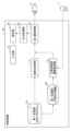
- FIG. 1 is a functional block diagram of a control device for a machine tool according to a first embodiment.
- FIG. It is a schematic diagram which shows the example of the cutting process in which the target surface roughness was set.
- FIG. 3 is a diagram showing an example of a machining program. It is a figure which shows the example of the table of tool surface roughness information.
- FIG. 11 is a functional block diagram of a control device for a machine tool according to a second embodiment.
- FIG. 13 is a diagram for explaining swing cutting.
- FIG. 3 is a functional block diagram of a control device for a machine tool according to a third embodiment.
- FIG. 13 is a functional block diagram of a control device for a machine tool according to a fourth embodiment.
- FIG. 13 is a functional block diagram of a control device for a machine tool according to a fifth embodiment. It is a functional block diagram of a control device of a machine tool concerning a 6th embodiment.
- FIG. 1 is a functional block diagram of a control device 1 for a machine tool according to the first embodiment.
- the control device 1 controls a machine tool that processes a cutting tool T and a workpiece while moving the workpiece relatively.
- the control device 1 operates at least one main axis that rotates the cutting tool T and the workpiece relatively, and at least one feed axis that moves the cutting tool T relatively to the workpiece, so that the tool moves the workpiece. It is used for cutting.
- the shape of the workpiece is not limited. In other words, even if the workpiece has a tapered part or an arcuate part on the machined surface and requires multiple feed axes (Z-axis and X-axis), if the workpiece is columnar or cylindrical and the feed axis is (Z-axis) is also applicable.
- the machine tool control device 1 includes a first memory unit 10, a surface roughness acquisition unit 11, a second memory unit 20, a tool surface roughness information acquisition unit 12, and a feed amount control unit 14.
- the machine tool control device 1 is configured using a computer including memories such as a ROM (read only memory) and a RAM (random access memory), a CPU (control processing unit), and a communication control unit, which are connected to each other via a bus, for example.
- the functions and operations of each of the above functional units are achieved by the cooperation of the CPU and memory mounted on the computer, and the control program stored in the memory.
- the machine tool control device 1 may be configured with a CNC (Computer Numerical Controller), and may be connected to a host computer (not shown) such as a CNC or a PLC (Programmable Logic Controller). In addition to the machining program, machining conditions such as rotational speed are input from the host computer to the control device 1 of the machine tool.
- a CNC Computer Numerical Controller
- PLC Programmable Logic Controller
- the first storage unit 10 stores a machining program to be executed by the machine tool.
- the machining program includes machining conditions for the workpiece.
- the machining conditions for the workpiece include the relative rotational speed of the workpiece and the cutting tool T around the center axis of the workpiece, the relative feed speed of the cutting tool T and the workpiece, the position command of the feed axis, the target surface roughness, etc. is included.
- the target surface roughness is a desired surface roughness value set for the workpiece to be machined.
- surface roughness include arithmetic mean roughness, maximum height that is the maximum distance between peaks and valleys, maximum peak height that is the maximum height from the average line of the surface, and height from the average line of the surface.
- Maximum valley depth which is the absolute value of the minimum height
- average height which is the average value of the heights of contour curve elements that are a set of adjacent peaks and valleys, and the height of the peaks of the contour curve elements mentioned above.
- the maximum cross-sectional height which is the sum of the maximum value and the maximum value of the valley depth, and the ratio of the loaded length of the contour curve element to the evaluation reference length at a predetermined cutting level (height% or ⁇ m). At least one of the load length ratios is included.
- typical indexes of surface roughness have been listed, the present invention is not limited to these, and other indexes of surface roughness may be used.
- the surface roughness acquisition unit 11 acquires the target surface roughness that is the target surface roughness from the machining program.
- the surface roughness acquisition unit 11 acquires the target surface roughness set in the machining program via the first storage unit 10 and outputs the acquired target surface roughness to the feed amount control unit 14. do.
- the second memory unit 20 stores tool surface roughness information related to the surface roughness of the cutting tool T.
- Tool surface roughness information related to the surface roughness of the cutting tool T includes information specifying the shape of the cutting tool T (tool shape information).
- the tool shape information is, for example, information indicating the shape of the cutting edge, such as nose R (mm) indicating the diameter of the cutting edge of the cutting tool T.
- the second memory unit 20 acquires and stores information specifying the shape of the cutting tool T from the machining program.
- the tool surface roughness information related to the surface roughness of the cutting tool T may be, for example, information representing the relationship between the feed rate and the surface roughness obtained when machining at that feed rate (for example, table data, relational expressions, etc.). good.
- the tool surface roughness information related to the surface roughness of the cutting tool T may be the information itself related to the surface roughness of the cutting tool T, or may be indirect information such as a tool number for specifying tool shape information. It may also be information.
- the second storage unit 20 stores the values of the nose R (mm) corresponding to each tool number as indirect information in a table format, and stores the values of the nose R (mm) corresponding to each tool number as indirect information, and A method may be used in which the cutting tool T in use is identified by identifying the tool number.
- the second storage unit 20 stores information indicating tool surface roughness information related to the current surface roughness of the cutting tool T, which is obtained from the cutting tool T connected to the control device 1.
- the second storage unit 20 stores the surface roughness of the cutting tool T after machining due to replacement of the cutting tool T, wear, etc. Changes in tool surface roughness information related to tool surface roughness will also be reflected.
- the information indicating the tool surface roughness information related to the current surface roughness of the cutting tool T obtained from the cutting tool T may be the information itself related to the surface roughness of the tool, or may be information such as the tool number etc. It may be indirect information.
- Detection of a change in tool surface roughness information related to the surface roughness of the cutting tool T is performed, for example, by detecting a change in the tool surface roughness information related to the surface roughness of the cutting tool T based on an external signal indicating that a new cutting tool T has been replaced.
- Information specifying roughness information may be included.
- changes in tool surface roughness information related to the surface roughness of the cutting tool T may be detected by, for example, image processing of an imaging device, or a contact or non-contact sensor may be used to detect changes in the shape of the cutting edge. It may also be detected by measuring.
- the tool surface roughness information acquisition unit 12 acquires tool surface roughness information of the cutting tool T from the second storage unit 20.
- the tool surface roughness information acquisition unit 12 may acquire the tool surface roughness information stored in the second storage unit 20, or specify the cutting tool T stored in the second storage unit 20. Alternatively, the tool surface roughness information may be specified from the information obtained.
- the tool surface roughness information acquisition section 12 outputs the acquired tool surface roughness information to the feed rate control section 14 .
- the feed amount control unit 14 determines feed amount information regarding the relative feed amount per revolution between the cutting tool T and the workpiece, and controls the drive of the motor 3.
- the feed rate control unit 14 calculates feed rate information based on the target surface roughness input from the surface roughness acquisition unit 11 and the tool surface roughness information input from the tool surface roughness information acquisition unit 12. .
- the feed amount information is information regarding the relative feed amount per rotation between the cutting tool T and the workpiece.
- the information regarding the feed amount is, for example, the feed amount F (mm/rev) per rotation of the main shaft. Further, the information regarding the feed amount may be the spindle rotation speed (rev/min) and the feed amount (mm/min). Therefore, the feed amount control section 14 may control both the feed shaft motor and the main shaft motor.
- the input unit 15 inputs information related to processing in response to an operator's input operation on an input means (not shown), such as a keyboard or a touch panel.
- the information related to processing input by the input unit 15 is stored in the first storage unit 10, etc., or input to each part of the control device 1.
- the display unit 16 displays various information regarding the machine tool, the control device 1, and machining.
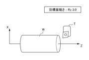
- FIG. 2 is a schematic diagram showing an example of cutting processing in which a target surface roughness is set.
- "Rz: 3.0" is set in advance as the target roughness in the machining program.
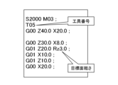
- FIG. 3 is a diagram showing an example of a machining program.
- the block "S2000 M03" is a description indicating that the main shaft is rotated in the normal direction.
- the block “T05” is a description indicating a tool number, which is information for specifying tool surface roughness information.
- Blocks starting with “G00” or “G01” such as “G00 Z40.0 X20.0” are descriptions that indicate behavior and coordinates such as positioning and linear interpolation.
- “Rz3.0” in the block “G01 Z20.0 Rz3.0” is a description indicating the target surface roughness.
- FIG. 4 is a diagram showing an example of a table of tool surface roughness information.
- the information is stored in the second storage unit 20, and at least information on the tool numbers T01 to T06 and the nose R corresponding to each of the tool numbers T01 to T06 is stored in a table format.
- the tool surface roughness information acquisition unit 12 acquires tool surface roughness information based on the tool number described in the machining program and a table as shown in FIG. In this example, nose R0.4 (mm) corresponding to tool number "T05" included in the machining program is acquired as tool surface roughness information.
- the method for acquiring tool surface roughness information is not particularly limited.
- the tool surface roughness information acquisition section 12 may, for example, acquire the tool surface roughness information by referring to the tool number and table stored in the second storage section 20, or may obtain the tool surface roughness information in advance based on the tool number and table.
- the identified tool surface roughness information may be acquired from the second storage unit 20.
- the feed rate control unit 14 determines the feed rate based on the target surface roughness acquired by the surface roughness acquisition unit 11 and the tool surface roughness information acquired by the tool surface roughness information acquisition unit 12.
- h is the target surface roughness Rz ( ⁇ m)
- f is the feed rate per spindle rotation (mm/rev)
- RE is the 7-nose R (mm) indicating the shape of the cutting edge of the cutting tool T, represents.
- the feed amount control unit 14 controls the motor 3 according to the feed amount based on the target surface roughness of the machining program until the target surface roughness is updated.
- the motor 3 is controlled by the feed rate calculated based on the new updated target surface roughness.
- the tool surface roughness information acquisition unit 12 monitors the state of the surface roughness of the cutting tool T. For this purpose, for example, it is monitored whether the cutting tool T has been replaced. When the replacement of the cutting tool T is detected, the tool surface roughness information acquisition unit 12 recalculates the feed amount information based on the surface roughness information of the replaced cutting tool T and the target surface roughness.
- the shape of the blade of the cutting tool T is monitored.
- the tool surface roughness information acquisition unit 12 acquires feed amount information based on the tool shape information indicating the changed shape of the blade of the cutting tool T and the target surface roughness. Recalculate.
- the control device 1 for a machine tool that performs machining while moving a cutting tool T and a workpiece W relative to one another provides the following effects.
- the machine tool control device 1 includes a surface roughness acquisition unit 11 that acquires the target surface roughness set for the workpiece W to be machined from the machining program, and A tool surface roughness information acquisition unit 12 that acquires related tool surface roughness information, and a cutting tool T and workpiece W based on the tool surface roughness information so that the surface roughness of the workpiece W becomes the target surface roughness. and a feed amount control unit 14 that determines feed amount information regarding the relative feed amount per revolution of the feed amount.
- the target surface roughness is set in the machining program, so the feed rate can be controlled based on the target surface roughness, the readability of the machining program can be improved, and the creation of the machining program is reduced. can be reduced.
- the feed amount information will be updated based on the target surface roughness and the surface roughness information of the cutting tool T. Since the calculation can be performed anew, the desired surface roughness can be obtained with high accuracy.
- the tool surface roughness information acquisition unit 12 detects a change in the tool surface roughness information of the cutting tool T
- the tool surface roughness information acquisition unit 12 acquires the tool surface roughness information after the change, and the feed rate control unit 14 , re-determine the feed rate information by reflecting the changed tool surface roughness information.
- the surface roughness acquisition unit 11 continues to use the target surface roughness previously acquired from the machining program until the next target surface roughness is acquired from the machining program, and the feed rate control unit 14 Output to.
- the target surface roughness command becomes modal information, making machining programming easier.
- FIG. 5 is a functional block diagram of a machine tool control device 1A according to the second embodiment.
- the control device 1A according to the second embodiment controls a machine tool that performs swing cutting while swinging a cutting tool T and a workpiece relative to each other.
- the machine tool control device 1A according to the second embodiment is different from the machine tool control device 1 according to the first embodiment in that it further includes a third storage unit 30 and a swing condition acquisition unit 13, and in the control of a feed amount control unit 14A, but the other configurations are the same as those of the first embodiment.
- FIG. 6 is a diagram for explaining swing cutting.
- at least one main axis S rotates the cutting tool T and the workpiece W relative to each other, and at least one feed axis moves the cutting tool T relative to the workpiece W. are operated to relatively rotate the cutting tool T and workpiece W, and perform cutting while relatively swinging the cutting tool T and workpiece W in the feeding direction.
- the tool path which is the locus of the cutting tool T, is set so that the current path partially overlaps the previous path. In other words, the part that was machined in the previous path is partially included in the current path, causing a miss called air cut in which the cutting edge of the cutting tool T separates from the surface of the workpiece W, and the chips are shredded.
- the third memory unit 30 stores the oscillation conditions for performing the oscillation cutting process.
- the oscillation conditions are obtained, for example, from the machining program.
- the oscillation conditions include information on the relative oscillation number per rotation between the cutting tool and the workpiece W, and information on the oscillation amplitude with respect to the relative feed amount per rotation between the cutting tool and the workpiece W.
- the information on the relative oscillation number per rotation between the cutting tool and the workpiece W includes an oscillation frequency magnification I (times) indicating the oscillation frequency per rotation of the spindle.
- the information on the oscillation amplitude with respect to the relative feed amount per rotation between the cutting tool and the workpiece W includes an oscillation amplitude magnification K (times) indicating the magnitude of the oscillation amplitude with respect to the magnitude of the feed amount per rotation of the spindle.
- the oscillation frequency magnification I (times) may be specified directly, or may be calculated from the oscillation frequency (Hz) and the spindle rotation speed S (1/min) after specifying the oscillation frequency (Hz).
- the oscillation amplitude magnification K (times) may be specified directly, or may be calculated from the oscillation amplitude (mm), feed rate (mm/min), and spindle rotation speed S (1/min) after specifying the oscillation amplitude (mm).
- the swing condition acquisition unit 13 acquires the swing conditions and outputs them to the feed amount control unit 14A.
- the swing condition acquisition unit 13 obtains the swing conditions from the third storage unit 30. Further, the swing condition acquisition unit 13 can obtain swing conditions specified by an external signal or the like.
- the swing condition acquisition section 13 outputs the obtained swing conditions to the feed amount control section 14A.
- the feed rate control unit 14A of the second embodiment acquires the target surface roughness input from the surface roughness acquisition unit 11, the tool surface roughness information input from the tool surface roughness information acquisition unit 12, and the swing condition acquisition.
- the feed amount information is calculated based on the swing conditions input from the section 13.
- the motor 3 is controlled based on the feed rate information calculated by the feed rate control section 14A, and swing cutting is performed.
- the updated swing conditions are stored in the third storage unit 30.
- the swing condition acquisition unit 13 monitors whether the swing conditions have changed. The swing conditions change, for example, when the swing conditions of a machining program are changed, or when the swing conditions are changed due to an external signal. When a change in the swing condition is detected, the swing condition acquisition unit 13 recalculates the feed amount information based on the changed swing condition, tool surface roughness information, and target surface roughness.
- the machine tool control device 1A includes a surface roughness acquisition section 11, a tool surface roughness information acquisition section 12, and an oscillation cutting operation that relatively oscillates a cutting tool T and a workpiece W.
- the feed amount controller 14A further includes a swing condition acquisition unit 13 that obtains conditions, and the feed rate control unit 14A controls the feed amount based on the tool surface roughness information and the swing conditions so that the surface roughness of the workpiece W becomes the target surface roughness. Determine quantity information.
- the control device 1 of the first embodiment even if the swing conditions change after the start of machining, in addition to the target surface roughness and the tool surface roughness information of the cutting edge of the cutting tool T, the changed swing Since the feed rate information is recalculated based on the conditions, the desired surface roughness can be obtained with high precision even in swing cutting. Further, it is possible to reduce the effort required to determine the feed rate in consideration of the swing conditions.
- the swing condition acquisition unit 13 of this embodiment detects a change in the swing condition, it acquires the swing condition after the change, and the feed amount control unit 14A reflects the swing condition after the change. Redetermine feed amount information. Thereby, changes in the swing conditions after the start of machining can be quickly reflected in the feed amount information.
- FIG. 7 is a functional block diagram of a machine tool control device 1B according to the third embodiment.
- the control device 1B according to the third embodiment controls a machine tool that performs cutting while relatively moving the cutting tool T and the workpiece.
- the machine tool control device 1B according to the third embodiment is different from the machine tool control device 1 according to the first embodiment in that it further includes a designated feed amount acquisition unit 17.
- the control of the feed amount control section 14B is different, and the other configurations are the same as in the first embodiment.
- the designated feed amount acquisition unit 17 acquires designated feed amount information in which information regarding the relative feed amount per revolution between the cutting tool T and the workpiece W is specified.
- the designated feed amount information is a numerical value set in advance, and is a numerical value in the same unit as the feed amount information.
- the designated feed amount information is set by being written in the machining program or input from the input unit 15.
- the designated feed amount acquisition unit 17 acquires the designated feed amount.
- the designated feed amount acquisition unit 17 acquires the designated feed amount information, it outputs the specified feed amount information to the feed amount control unit 14B.
- the feed rate control unit 14B of the third embodiment uses the specified feed rate information instead of the specified feed rate information calculated based on the target surface roughness and tool surface roughness information. Prioritize feed amount information. Therefore, the motor 3 is controlled based on the designated feed amount information.
- the machine tool control device 1B When the machine tool control device 1B according to the present embodiment acquires designated feed amount information in which information regarding the relative feed amount per revolution between the cutting tool T and the workpiece W is specified, the machine tool control device 1B performs a to control the relative feed amount per revolution between the cutting tool T and the work W. This makes it possible to respond flexibly to cases where it is better to specify the feed rate, such as when there are unprocessed blocks.
- the designated feed amount acquisition unit 17 of the third embodiment may be added to the configuration of the second embodiment that performs swing cutting.
- the feed amount control unit 14B acquires the specified feed amount information, it controls the motor 3 with priority given to the specified feed amount information.
- FIG. 8 is a functional block diagram of a machine tool control device 1C according to the fourth embodiment.
- the machine tool control device 1C according to the fourth embodiment is different from the machine tool control device 1 according to the first embodiment in that it further includes a deviation correction value acquisition unit 18. The difference is in the control of the feed amount control section 14C, and the other configurations are the same as in the first embodiment.
- the deviation correction value acquisition unit 18 obtains a deviation correction value that corrects the deviation between the theoretical value and the measured value of surface roughness.
- the deviation correction value is calculated based on, for example, the processing conditions acquired from the first storage unit 10.
- the machining conditions are calculated based on machining conditions including at least one of the material of the cutting tool edge, the shape of the cutting tool edge, the material of the workpiece W, the cutting speed, the depth of cut, and the angle of cut. Further, the deviation correction value may be calculated based on machine parameters as necessary.
- the deviation correction value acquisition unit 18 outputs the obtained deviation correction value to the feed amount control unit 14C.
- the feed rate control unit 14C of the fourth embodiment acquires the target surface roughness input from the surface roughness acquisition unit 11, the tool surface roughness information input from the tool surface roughness information acquisition unit 12, and the deviation correction value.
- the feed amount information is calculated based on the deviation correction value obtained from the section 18.
- the motor 3 is controlled based on the feed rate information calculated by the feed rate control section 14C, and cutting is performed.
- the deviation correction value acquisition unit 18 may also use machine learning such as supervised learning.
- a learning model may be constructed from a large amount of data set that uses feed amount information related to the processing conditions and feed amount as input and outputs the actual surface roughness, and the deviation correction value may be determined based on the surface roughness that is the output result of the learning model.
- the machine tool control device 1C includes a deviation correction value acquisition unit 18 that obtains a deviation correction value for correcting the deviation between the theoretical surface roughness value and the actual measured value of the surface roughness of the workpiece W. Furthermore, the feed amount control unit 14C determines the feed amount information by taking the deviation correction value into consideration. As a result, the feed amount information is determined taking into account the difference between the theoretical value of surface roughness and the actual value of surface roughness, so that processing can be performed with even higher precision to achieve the desired surface roughness.
- the deviation correction value acquisition unit 18 of the fourth embodiment may be added to the configuration of the second embodiment that performs swing cutting. In this case, it is preferable that the deviation correction value acquisition unit 18 determines the feed amount information by taking into account the swing conditions in addition to the processing conditions. When combining machine learning, it is preferable to add a swing condition to the input of the data set.
- FIG. 9 is a functional block diagram of a control device 1D for a machine tool according to the fifth embodiment.
- the machine tool control device 1D according to the fifth embodiment has a surface roughness correction value acquisition unit 21 and a surface roughness
- the second embodiment differs in that it further includes a length determination section 22 and in the control of a feed amount control section 14D, and the other configurations are the same as in the first embodiment.
- the surface roughness correction value acquisition unit 21 acquires a surface roughness correction value for correcting the target surface roughness.
- the surface roughness correction value acquisition unit 21 is, for example, a magnification (correction coefficient) specified by an operator operating an input means such as a dial of the input unit 15 or by operating an external computer. The operator can adjust the surface roughness by setting the target surface roughness as 100% of the standard and changing it to 90%, 110%, etc.
- the surface roughness determination unit 22 corrects the target surface roughness input from the surface roughness acquisition unit 11 using the surface roughness correction value input from the surface roughness correction value acquisition unit 21, and Output to 14.
- the feed rate control unit 14D of the fifth embodiment uses the corrected target surface roughness inputted from the surface roughness determination unit 22 and the tool surface roughness information inputted from the tool surface roughness information acquisition unit 12. Calculate feed amount information based on this.
- the motor 3 is controlled based on the feed amount information calculated by the feed amount control section 14D, and cutting is performed.
- the machine tool control device 1D according to the fifth embodiment provides the following advantages:
- the machine tool control device 1D includes a surface roughness correction value acquisition unit 21 that acquires a surface roughness correction value for correcting the target surface roughness, and a target surface roughness acquired by the surface roughness acquisition unit 11. and a surface roughness determination unit 22 that determines the surface roughness based on the surface roughness correction value acquired by the surface roughness correction value acquisition unit 21.
- the feed amount information is determined so that the surface roughness determined by the surface roughness determining section 22 is obtained. This allows the operator to adjust the accuracy of the surface roughness after machining without changing the machining program.
- the surface roughness correction value acquisition unit 21 and the surface roughness determination unit 22 of the fifth embodiment may be added to the configuration of other embodiments such as the second embodiment that performs swing cutting.
- FIG. 10 is a functional block diagram of a machine tool control device 1E according to the sixth embodiment. As shown in FIG. 10, the machine tool control device 1E according to the sixth embodiment differs from the machine tool control device 1 according to the first embodiment in that it further includes an output processing section 23. However, other configurations are the same as in the first embodiment.
- the output processing unit 23 executes display processing for outputting the feed amount information determined by the feed amount control unit 14 to the display unit 16.
- the display unit 16 displays the feed amount information processed by the output processing unit 23 on the screen.
- the display unit 16 displays, for example, the feed amount F (mm/rev) per spindle rotation, the spindle rotation speed (rev/min), the feed amount (mm/min), etc. on the screen as feed amount information. do.
- the machine tool control device 1E further includes an output processing section 23 that outputs the feed amount information determined by the feed amount control section 14 to the display section 16. Thereby, the operator can check the feed amount information displayed on the display screen of the display unit 16, etc., and therefore can easily check safety and production plans.
- output processing unit 23 of the sixth embodiment may be added to the configuration of other embodiments, such as the second embodiment that performs swing cutting.
- Machine tool control device 11
- Surface roughness acquisition section 12 Tool surface roughness information acquisition section 13
- Feed rate control section 16 Display section 17
- Deviation correction value acquisition section 21 Surface roughness correction value acquisition section 22
- Surface roughness determination section 23 Output processing section
Abstract
Provided is a feature with which it is possible to precisely achieve a desired surface roughness even if a cutting tool is replaced after the start of processing or if the shape of a blade edge of the cutting tool has changed, to improve the readability of a processing program, and to reduce the time and effort required in creating the processing program. Specifically, provided is a control device 1 for a machine tool that processes a workpiece W while moving the workpiece W relative to a cutting tool T, the machine tool control device 1 comprising: a surface roughness acquisition unit 11 that acquires, from a processing program, a target surface roughness set for a workpiece W being processed; a tool surface roughness information acquisition unit 12 that acquires tool surface roughness information relating to the surface roughness of the cutting tool T; and a feeding amount control unit 14 that, on the basis of the tool surface roughness information, determines feeding amount information relating to a feeding amount per relative rotation of the cutting tool T and the workpiece W such that the surface roughness of the workpiece W reaches the target surface roughness.
Description
本開示は、工作機械の制御装置に関する。
The present disclosure relates to a control device for a machine tool.
従来、切削加工では、加工対象のワークを移動させる主軸の送り量を加工プログラム等に予め指定し、切削加工を行う技術が知られている(例えば、特許文献1及び特許文献2参照)。
Conventionally, in cutting processing, a technique is known in which the feed rate of a spindle that moves a workpiece to be processed is specified in advance in a processing program etc., and cutting processing is performed (for example, see Patent Document 1 and Patent Document 2).
ところで、加工後のワークの指標の1つとして面粗さがある。面粗さは、切削工具の刃先の形状や送り量によって決まる。そのため、加工後のワークが所望の面粗さを得ることができるように単位時間当たりの主軸の送り量を決定していた。
By the way, surface roughness is one of the indicators of a workpiece after machining. Surface roughness is determined by the shape of the cutting tool's cutting edge and the feed rate. Therefore, the amount of feed of the spindle per unit time has been determined so that the workpiece after machining can obtain the desired surface roughness.
しかしながら、切削加工の途中で切削工具の変更を行ったり、摩耗等に起因して切削工具の刃先の形状が変わったりすると、送り量を変更する必要があるにも関わらす、そのままの送り量で切削加工が継続されてしまう。適切な条件に対応した送り量でなければ、所望の面粗さを得ることができないおそれがある。
However, if the cutting tool is changed during the cutting process, or if the shape of the cutting tool's cutting edge changes due to wear, etc., the feed rate needs to be changed, but if the feed rate remains unchanged. Cutting continues. Unless the feed rate corresponds to appropriate conditions, there is a possibility that the desired surface roughness cannot be obtained.
また、面粗さを反映した送り量を加工プログラムに設定する方法では、指標の1つである面粗さを加工プログラムから把握することが難しく、可読性の向上という点でも従来技術には改善の余地があった。
In addition, with the method of setting the feed amount that reflects the surface roughness in the machining program, it is difficult to understand the surface roughness, which is one of the indicators, from the machining program, and there is no improvement in conventional technology in terms of improving readability. There was room.
また、面粗さを反映した送り量を加工プログラムに設定する方法では、加工後のワークが所望の面粗さを得ることができるような送り量を算出する作業と、それを加工プログラムに反映する作業を必要とするため、これらの作業には手間を要した。
In addition, in the method of setting a feed amount that reflects the surface roughness in the machining program, it is necessary to calculate the feed amount that allows the workpiece to obtain the desired surface roughness after machining, and to reflect it in the machining program. These tasks required time and effort.
本開示は上記課題に鑑みてなされたものであり、加工開始後に切削工具の変更を行ったり、切削工具の刃先の形状が変わったとしても所望の面粗さを精度良く得ることができ、かつ加工プログラムの可読性を向上できるとともに加工プログラム作成の手間を削減できる技術を提供することを目的とする。
The present disclosure has been made in view of the above problems, and even if the cutting tool is changed after the start of machining or the shape of the cutting tool's cutting edge changes, the desired surface roughness can be obtained with high accuracy, and The purpose of this invention is to provide a technology that can improve the readability of machining programs and reduce the effort required to create machining programs.
本開示は、切削工具とワークを相対的に移動させながら加工する工作機械の制御装置であって、加工対象の前記ワークに対して設定される目標面粗さを加工プログラムから取得する面粗さ取得部と、前記切削工具の面粗さに関する工具面粗度情報を取得する工具面粗度情報取得部と、前記ワークの面粗さが前記目標面粗さになるように、前記工具面粗度情報に基づいて前記切削工具と前記ワークの相対的な1回転あたりの送り量に関する送り量情報を決定する送り量制御部と、を備える、工作機械の制御装置である。
The present disclosure relates to a control device for a machine tool that processes a cutting tool and a workpiece while relatively moving the workpiece, the surface roughness control device acquiring a target surface roughness set for the workpiece to be machined from a machining program. an acquisition unit; a tool surface roughness information acquisition unit that acquires tool surface roughness information regarding the surface roughness of the cutting tool; and a tool surface roughness information acquisition unit that acquires tool surface roughness information regarding the surface roughness of the cutting tool; The present invention is a control device for a machine tool, comprising: a feed rate control unit that determines feed rate information regarding a relative feed rate per rotation of the cutting tool and the workpiece based on degree information.
本開示によれば、加工開始後に切削工具の変更を行ったり、切削工具の刃先の形状が変わったとしても所望の面粗さを精度良く得ることができ、かつ加工プログラムの可読性を向上できるとともに加工プログラム作成の手間を削減できる技術を提供することができる。
According to the present disclosure, even if the cutting tool is changed after the start of machining or the shape of the cutting edge of the cutting tool is changed, the desired surface roughness can be obtained with high precision, and the readability of the machining program can be improved. It is possible to provide technology that can reduce the effort required to create machining programs.
以下、本開示の実施形態について、図面を参照して詳しく説明する。なお、第2実施形態以降の説明において、第1実施形態と共通する構成については同一符号を付し、その説明を適宜省略する。
Hereinafter, embodiments of the present disclosure will be described in detail with reference to the drawings. In addition, in the description of the second embodiment and subsequent embodiments, the same reference numerals are given to the same components as in the first embodiment, and the description thereof will be omitted as appropriate.
[第1実施形態]
図1は、第1実施形態に係る工作機械の制御装置1の機能ブロック図である。第1実施形態に係る制御装置1は、切削工具Tとワークを相対的に移動させながら加工する工作機械を制御する。制御装置1は、切削工具Tとワークとを相対的に回転させる少なくとも一つの主軸と、切削工具Tをワークに対して相対移動させる少なくとも一つの送り軸と、を動作させることで、工具によりワークを切削加工するものである。 [First embodiment]
FIG. 1 is a functional block diagram of a control device 1 for a machine tool according to the first embodiment. The control device 1 according to the first embodiment controls a machine tool that processes a cutting tool T and a workpiece while moving the workpiece relatively. The control device 1 operates at least one main axis that rotates the cutting tool T and the workpiece relatively, and at least one feed axis that moves the cutting tool T relatively to the workpiece, so that the tool moves the workpiece. It is used for cutting.
なお、図1では、便宜上、一つの送り軸を駆動するモータ3と切削工具Tのみを示している。また、本実施形態に係る切削加工では、ワークの形状は限定されない。即ち、ワークが加工面にテーパ部や円弧状部を有することで複数の送り軸(Z軸及びX軸)が必要となる場合でも、ワークが円柱状や円筒状で送り軸が特定の1軸(Z軸)で足りる場合であっても、適用可能である。
Note that in FIG. 1, for convenience, only the motor 3 that drives one feed shaft and the cutting tool T are shown. Further, in the cutting process according to this embodiment, the shape of the workpiece is not limited. In other words, even if the workpiece has a tapered part or an arcuate part on the machined surface and requires multiple feed axes (Z-axis and X-axis), if the workpiece is columnar or cylindrical and the feed axis is (Z-axis) is also applicable.
図1に示されるように、第1実施形態に係る工作機械の制御装置1は、第1記憶部10と、面粗さ取得部11と、第2記憶部20と、工具面粗度情報取得部12と、送り量制御部14と、を備える。工作機械の制御装置1は、例えば、バスを介して互いに接続された、ROM(read only memory)やRAM(random access memory)等のメモリ、CPU(control processing unit)、及び通信制御部を備えたコンピュータを用いて構成される。上記各機能部の機能及び動作は、上記コンピュータに搭載されたCPU、メモリ、及び該メモリに記憶された制御プログラムが協働することにより達成される。
As shown in FIG. 1, the machine tool control device 1 according to the first embodiment includes a first memory unit 10, a surface roughness acquisition unit 11, a second memory unit 20, a tool surface roughness information acquisition unit 12, and a feed amount control unit 14. The machine tool control device 1 is configured using a computer including memories such as a ROM (read only memory) and a RAM (random access memory), a CPU (control processing unit), and a communication control unit, which are connected to each other via a bus, for example. The functions and operations of each of the above functional units are achieved by the cooperation of the CPU and memory mounted on the computer, and the control program stored in the memory.
工作機械の制御装置1は、CNC(Computer Numerical Controller)で構成されてよく、また、CNCやPLC(Programmable Logic Controller)等の上位コンピュータ(不図示)に接続されていてよい。上位コンピュータから、加工プログラムの他、回転速度等の加工条件等が工作機械の制御装置1に入力される。
The machine tool control device 1 may be configured with a CNC (Computer Numerical Controller), and may be connected to a host computer (not shown) such as a CNC or a PLC (Programmable Logic Controller). In addition to the machining program, machining conditions such as rotational speed are input from the host computer to the control device 1 of the machine tool.
第1記憶部10は、工作機械に実行させる加工プログラムを記憶する。加工プログラムには、ワークの加工条件等が含まれる。ワークの加工条件には、ワークの中心軸線まわりにおけるワーク及び切削工具Tの相対的な回転速度、切削工具T及びワークの相対的な送り速度、及び、送り軸の位置指令、目標面粗さ等が含まれる。
The first storage unit 10 stores a machining program to be executed by the machine tool. The machining program includes machining conditions for the workpiece. The machining conditions for the workpiece include the relative rotational speed of the workpiece and the cutting tool T around the center axis of the workpiece, the relative feed speed of the cutting tool T and the workpiece, the position command of the feed axis, the target surface roughness, etc. is included.
目標面粗さは、加工対象のワークに対して設定される所望の面粗さの値である。面粗さとしては、例えば、算術平均粗さ、山と谷の距離の最大値である最大高さ、表面の平均線からの高さの最大値である最大山高さ、表面の平均線からの高さの最小値の絶対値である最大谷深さ、隣り合う山と谷を一組とした輪郭曲線要素の高さの平均値である平均高さ、上記輪郭曲線要素の山の高さの最大値と谷の深さの最大値との和である最大断面高さ、及び、所定の切断レベル(高さ%又はμm)における上記輪郭曲線要素の負荷長さの評価基準長さに対する比率である負荷長さ率のうち、少なくとも一つが含まれる。面粗さの指標として代表的なもの列挙したが、これらに限定されることなく、他の面粗さの指標を用いても構わない。
The target surface roughness is a desired surface roughness value set for the workpiece to be machined. Examples of surface roughness include arithmetic mean roughness, maximum height that is the maximum distance between peaks and valleys, maximum peak height that is the maximum height from the average line of the surface, and height from the average line of the surface. Maximum valley depth which is the absolute value of the minimum height, average height which is the average value of the heights of contour curve elements that are a set of adjacent peaks and valleys, and the height of the peaks of the contour curve elements mentioned above. The maximum cross-sectional height, which is the sum of the maximum value and the maximum value of the valley depth, and the ratio of the loaded length of the contour curve element to the evaluation reference length at a predetermined cutting level (height% or μm). At least one of the load length ratios is included. Although typical indexes of surface roughness have been listed, the present invention is not limited to these, and other indexes of surface roughness may be used.
面粗さ取得部11は、加工プログラムから目標の面粗さとなる目標面粗さを取得する。第1実施形態では、面粗さ取得部11は、第1記憶部10を介して加工プログラムに設定される目標面粗さを取得し、取得した目標面粗さを送り量制御部14に出力する。
The surface roughness acquisition unit 11 acquires the target surface roughness that is the target surface roughness from the machining program. In the first embodiment, the surface roughness acquisition unit 11 acquires the target surface roughness set in the machining program via the first storage unit 10 and outputs the acquired target surface roughness to the feed amount control unit 14. do.
第2記憶部20は、切削工具Tの面粗さに関係する工具面粗度情報を記憶する。切削工具Tの面粗さに関係する工具面粗度情報として、切削工具Tの形状を特定する情報(工具形状情報)が挙げられる。工具形状情報は、例えば、切削工具Tの刃先の径の長さを示すノーズR(mm)等の刃先の形状を示す情報である。第2記憶部20は、加工プログラムから切削工具Tの形状を特定する情報を取得し、記憶する。
The second memory unit 20 stores tool surface roughness information related to the surface roughness of the cutting tool T. Tool surface roughness information related to the surface roughness of the cutting tool T includes information specifying the shape of the cutting tool T (tool shape information). The tool shape information is, for example, information indicating the shape of the cutting edge, such as nose R (mm) indicating the diameter of the cutting edge of the cutting tool T. The second memory unit 20 acquires and stores information specifying the shape of the cutting tool T from the machining program.
切削工具Tの面粗さに関係する工具面粗度情報は、例えば、送り速度とその送り速度で加工した時に得られる面粗さの関係を表す情報(例えばテーブルデータや、関係式等)でも良い。
The tool surface roughness information related to the surface roughness of the cutting tool T may be, for example, information representing the relationship between the feed rate and the surface roughness obtained when machining at that feed rate (for example, table data, relational expressions, etc.). good.
切削工具Tの面粗さに関係する工具面粗度情報は、切削工具Tの面粗さに関係する情報そのものであってもよいし、工具形状情報を特定するための工具番号等の間接的な情報であってもよい。この場合、第2記憶部20に、間接的な情報としての工具番号ごとに対応するノーズR(mm)の数値をテーブル形式で記憶し、加工プログラム中の工具番号や接続される切削工具Tの工具番号を特定することで、使用中の切削工具Tを特定する方式を用いてもよい。
The tool surface roughness information related to the surface roughness of the cutting tool T may be the information itself related to the surface roughness of the cutting tool T, or may be indirect information such as a tool number for specifying tool shape information. It may also be information. In this case, the second storage unit 20 stores the values of the nose R (mm) corresponding to each tool number as indirect information in a table format, and stores the values of the nose R (mm) corresponding to each tool number as indirect information, and A method may be used in which the cutting tool T in use is identified by identifying the tool number.
また、第2記憶部20は、制御装置1に接続される切削工具Tから取得された現在の切削工具Tの面粗さに関係する工具面粗度情報を示す情報を記憶する。切削工具Tから面粗さに関係する工具面粗度情報を示す情報を取得することにより、第2記憶部20には、切削工具Tの交換や摩耗等による切削工具Tの加工後の面粗さに関係する工具面粗度情報の変化も反映されることになる。切削工具Tから取得された現在の切削工具Tの面粗さに関係する工具面粗度情報を示す情報は、工具の面粗さに関係する情報そのものであってもよいし、工具番号等の間接的な情報であってもよい。切削工具Tの面粗さに関係する工具面粗度情報の変化の検出は、例えば、新たな切削工具Tが交換されたことを示す外部信号に切削工具Tの面粗さに関係する工具面粗度情報を特定する情報が含まれていてもよい。また、切削工具Tの面粗さに関係する工具面粗度情報の変化の検出は、例えば、撮像装置の画像処理により検出してもよいし、接触式又は非接触式のセンサによって刃先の形状を測定して検出してもよい。
Additionally, the second storage unit 20 stores information indicating tool surface roughness information related to the current surface roughness of the cutting tool T, which is obtained from the cutting tool T connected to the control device 1. By acquiring information indicating tool surface roughness information related to surface roughness from the cutting tool T, the second storage unit 20 stores the surface roughness of the cutting tool T after machining due to replacement of the cutting tool T, wear, etc. Changes in tool surface roughness information related to tool surface roughness will also be reflected. The information indicating the tool surface roughness information related to the current surface roughness of the cutting tool T obtained from the cutting tool T may be the information itself related to the surface roughness of the tool, or may be information such as the tool number etc. It may be indirect information. Detection of a change in tool surface roughness information related to the surface roughness of the cutting tool T is performed, for example, by detecting a change in the tool surface roughness information related to the surface roughness of the cutting tool T based on an external signal indicating that a new cutting tool T has been replaced. Information specifying roughness information may be included. In addition, changes in tool surface roughness information related to the surface roughness of the cutting tool T may be detected by, for example, image processing of an imaging device, or a contact or non-contact sensor may be used to detect changes in the shape of the cutting edge. It may also be detected by measuring.
工具面粗度情報取得部12は、第2記憶部20から切削工具Tの工具面粗度情報を取得する。工具面粗度情報取得部12は、第2記憶部20に記憶されている工具面粗度情報を取得する方式であってもよいし、第2記憶部20に記憶される切削工具Tを特定する情報から工具面粗度情報を特定する方式であってもよい。工具面粗度情報取得部12は、取得した工具面粗度情報を送り量制御部14に出力する。
The tool surface roughness information acquisition unit 12 acquires tool surface roughness information of the cutting tool T from the second storage unit 20. The tool surface roughness information acquisition unit 12 may acquire the tool surface roughness information stored in the second storage unit 20, or specify the cutting tool T stored in the second storage unit 20. Alternatively, the tool surface roughness information may be specified from the information obtained. The tool surface roughness information acquisition section 12 outputs the acquired tool surface roughness information to the feed rate control section 14 .
送り量制御部14は、切削工具Tとワークの相対的な1回転あたりの送り量に関する送り量情報を決定し、モータ3の駆動を制御する。送り量制御部14は、面粗さ取得部11から入力される目標面粗さと、工具面粗度情報取得部12から入力される工具面粗度情報と、に基づいて送り量情報を算出する。
The feed amount control unit 14 determines feed amount information regarding the relative feed amount per revolution between the cutting tool T and the workpiece, and controls the drive of the motor 3. The feed rate control unit 14 calculates feed rate information based on the target surface roughness input from the surface roughness acquisition unit 11 and the tool surface roughness information input from the tool surface roughness information acquisition unit 12. .
送り量情報は、切削工具Tとワークの相対的な1回転あたりの送り量に関する情報である。送り量に関する情報は、例えば、主軸1回転あたりの送り量F(mm/rev)である。また、送り量に関する情報は、主軸回転数(rev/min)と送り量(mm/min)であってもよい。従って、送り量制御部14は送り軸のモータと主軸のモータの両方を制御してもよい。
The feed amount information is information regarding the relative feed amount per rotation between the cutting tool T and the workpiece. The information regarding the feed amount is, for example, the feed amount F (mm/rev) per rotation of the main shaft. Further, the information regarding the feed amount may be the spindle rotation speed (rev/min) and the feed amount (mm/min). Therefore, the feed amount control section 14 may control both the feed shaft motor and the main shaft motor.
入力部15は、例えばキーボードやタッチパネル等の入力手段(不図示)に対するオペレータの入力操作に応じて、加工に関する情報を入力する。入力部15により入力された加工に関する情報は、第1記憶部10等に記憶されたり、制御装置1の各部に入力されたりする。
The input unit 15 inputs information related to processing in response to an operator's input operation on an input means (not shown), such as a keyboard or a touch panel. The information related to processing input by the input unit 15 is stored in the first storage unit 10, etc., or input to each part of the control device 1.
表示部16は、工作機械、制御装置1及び加工に関する各種の情報を表示する。
The display unit 16 displays various information regarding the machine tool, the control device 1, and machining.
次に、第1実施形態に係る制御装置1の制御処理の一例について説明する。図2は、目標面粗さが設定された切削加工の例を示す模式図である。図2の例では、加工プログラムに予め目標設定粗さとして「Rz:3.0」が設定される。
Next, an example of the control processing of the control device 1 according to the first embodiment will be described. FIG. 2 is a schematic diagram showing an example of cutting processing in which a target surface roughness is set. In the example of FIG. 2, "Rz: 3.0" is set in advance as the target roughness in the machining program.
図3は、加工プログラムの例を示す図である。図3の加工プログラムのうち、「S2000 M03」のブロックは、主軸を正回転させることを示す記述である。「T05」のブロックは、工具面粗度情報を特定するための情報である工具番号を示す記述である。「G00 Z40.0 X20.0」等の「G00」や「G01」から始まるブロックは、位置決めや直線補間等の挙動や座標を示す記述である。このうち、「G01 Z20.0 Rz3.0」のブロックにおける「Rz3.0」は、目標面粗さを示す記述である。加工プログラムに基づく運転が開始されると、制御装置1の面粗さ取得部11は、「G01 Z20.0 Rz3.0」のブロックの解析を開始し、目標面粗さRzが3.0であることを取得する。
FIG. 3 is a diagram showing an example of a machining program. In the machining program shown in FIG. 3, the block "S2000 M03" is a description indicating that the main shaft is rotated in the normal direction. The block "T05" is a description indicating a tool number, which is information for specifying tool surface roughness information. Blocks starting with "G00" or "G01" such as "G00 Z40.0 X20.0" are descriptions that indicate behavior and coordinates such as positioning and linear interpolation. Among these, "Rz3.0" in the block "G01 Z20.0 Rz3.0" is a description indicating the target surface roughness. When the operation based on the machining program is started, the surface roughness acquisition unit 11 of the control device 1 starts analyzing the block "G01 Z20.0 Rz3.0" and determines that the target surface roughness Rz is 3.0. get something out of it.
図4は、工具面粗度情報のテーブルの例を示す図である。図4の例では、第2記憶部20に記憶されるものであり、少なくとも工具番号T01~T06と工具番号T01~T06のそれぞれに対応するノーズRの情報がテーブル形式で記憶される。工具面粗度情報取得部12は、加工プログラムに記述される工具番号と、図4に示すようなテーブルと、に基づいて工具面粗度情報を取得する。この例では、加工プログラムに含まれていた工具番号「T05」に対応するノーズR0.4(mm)が工具面粗度情報として取得される。
FIG. 4 is a diagram showing an example of a table of tool surface roughness information. In the example of FIG. 4, the information is stored in the second storage unit 20, and at least information on the tool numbers T01 to T06 and the nose R corresponding to each of the tool numbers T01 to T06 is stored in a table format. The tool surface roughness information acquisition unit 12 acquires tool surface roughness information based on the tool number described in the machining program and a table as shown in FIG. In this example, nose R0.4 (mm) corresponding to tool number "T05" included in the machining program is acquired as tool surface roughness information.
なお、工具面粗度情報の取得方法は特に限定されるわけではない。工具面粗度情報取得部12は、例えば、第2記憶部20に記憶される工具番号とテーブルを参照して工具面粗度情報を取得してもよいし、工具番号とテーブルに基づいて予め特定された工具面粗度情報を第2記憶部20から取得してもよい。
Note that the method for acquiring tool surface roughness information is not particularly limited. The tool surface roughness information acquisition section 12 may, for example, acquire the tool surface roughness information by referring to the tool number and table stored in the second storage section 20, or may obtain the tool surface roughness information in advance based on the tool number and table. The identified tool surface roughness information may be acquired from the second storage unit 20.
送り量制御部14は、面粗さ取得部11が取得した目標面粗さと、工具面粗度情報取得部12が取得した工具面粗度情報と、に基づいて送り速度を決定する。送り量制御部14は、最大深さRzを目標面粗さの指標とする場合、以下の式を利用して送り速度を算出する。この例では、目標面粗さh=3.0、ノーズR=0.4を下記の式に代入すると、送り量F≒0.098(mm/rev)となる。
The feed rate control unit 14 determines the feed rate based on the target surface roughness acquired by the surface roughness acquisition unit 11 and the tool surface roughness information acquired by the tool surface roughness information acquisition unit 12. When using the maximum depth Rz as an index of target surface roughness, the feed rate control unit 14 calculates the feed rate using the following formula. In this example, by substituting the target surface roughness h=3.0 and nose R=0.4 into the following equation, the feed amount F≈0.098 (mm/rev) is obtained.

数式(1)中、hは目標面粗さRz(μm)、fは主軸1回転あたりの送り量(mm/rev)、REは切削工具Tの刃先の形状を示す7ノーズR(mm)、を表している。
In formula (1), h is the target surface roughness Rz (μm), f is the feed rate per spindle rotation (mm/rev), RE is the 7-nose R (mm) indicating the shape of the cutting edge of the cutting tool T, represents.
送り量制御部14は、加工プログラムの目標面粗さが更新されるまで当該目標面粗さに基づく送り量によってモータ3を制御する。加工プログラムの目標面粗さが更新されると、更新された新たな目標面粗さに基づいて算出した送り量によるモータ3の制御を行う。
The feed amount control unit 14 controls the motor 3 according to the feed amount based on the target surface roughness of the machining program until the target surface roughness is updated. When the target surface roughness of the machining program is updated, the motor 3 is controlled by the feed rate calculated based on the new updated target surface roughness.
また、工具面粗度情報取得部12は、切削工具Tの面粗度の状態を監視する。そのために例えば、切削工具Tが交換されたかどうかを監視する。切削工具Tの交換が検出されると、工具面粗度情報取得部12は、交換した切削工具Tの面粗度情報と目標面粗さに基づいて送り量情報を再算出する。
Additionally, the tool surface roughness information acquisition unit 12 monitors the state of the surface roughness of the cutting tool T. For this purpose, for example, it is monitored whether the cutting tool T has been replaced. When the replacement of the cutting tool T is detected, the tool surface roughness information acquisition unit 12 recalculates the feed amount information based on the surface roughness information of the replaced cutting tool T and the target surface roughness.
また、切削工具Tの面粗度の状態を監視する別の手段として、切削工具Tの刃の形状を監視する。切削工具Tの刃の形状の変化が検出されると、工具面粗度情報取得部12は、変化した切削工具Tの刃の形状を示す工具形状情報と目標面粗さに基づいて送り量情報を再算出する。
Additionally, as another means of monitoring the state of the surface roughness of the cutting tool T, the shape of the blade of the cutting tool T is monitored. When a change in the shape of the blade of the cutting tool T is detected, the tool surface roughness information acquisition unit 12 acquires feed amount information based on the tool shape information indicating the changed shape of the blade of the cutting tool T and the target surface roughness. Recalculate.
第1実施形態に係る切削工具TとワークWを相対的に移動させながら加工する工作機械の制御装置1によれば、以下の効果が奏される。
The control device 1 for a machine tool that performs machining while moving a cutting tool T and a workpiece W relative to one another according to the first embodiment provides the following effects.
本実施形態に係る工作機械の制御装置1では、加工対象のワークWに対して設定される目標面粗さを加工プログラムから取得する面粗さ取得部11と、切削工具Tの面粗さに関係する工具面粗度情報を取得する工具面粗度情報取得部12と、ワークWの面粗さが目標面粗さになるように、工具面粗度情報に基づいて切削工具TとワークWの相対的な1回転あたりの送り量に関する送り量情報を決定する送り量制御部14と、を備えた。これにより、加工プログラム中に目標面粗さが設定されることになるので、当該目標面粗さに基づいて送り量を制御できるとともに、加工プログラムの可読性を向上でき、かつ加工プログラムの作成の手間を削減できる。また、加工開始後に切削工具Tが変わったり、切削工具Tの刃先の形状(例えば、ノーズR)が変わったとしても、目標面粗さと切削工具Tの面粗度情報に基づいて送り量情報を改めて算出できるので、所望の面粗さを精度良く得ることができる。
The machine tool control device 1 according to the present embodiment includes a surface roughness acquisition unit 11 that acquires the target surface roughness set for the workpiece W to be machined from the machining program, and A tool surface roughness information acquisition unit 12 that acquires related tool surface roughness information, and a cutting tool T and workpiece W based on the tool surface roughness information so that the surface roughness of the workpiece W becomes the target surface roughness. and a feed amount control unit 14 that determines feed amount information regarding the relative feed amount per revolution of the feed amount. As a result, the target surface roughness is set in the machining program, so the feed rate can be controlled based on the target surface roughness, the readability of the machining program can be improved, and the creation of the machining program is reduced. can be reduced. In addition, even if the cutting tool T changes after machining has started, or the shape of the cutting edge of the cutting tool T (for example, nose R) changes, the feed amount information will be updated based on the target surface roughness and the surface roughness information of the cutting tool T. Since the calculation can be performed anew, the desired surface roughness can be obtained with high accuracy.
また、本実施形態では、工具面粗度情報取得部12は、切削工具Tの工具面粗度情報の変化を検出すると、変化後の工具面粗度情報を取得し、送り量制御部14は、変化後の工具面粗度情報を反映して送り量情報を再決定する。これにより、切削工具Tの交換や摩耗による切削工具Tの刃先の変化を速やかに送り量情報に反映できる。
Further, in this embodiment, when the tool surface roughness information acquisition unit 12 detects a change in the tool surface roughness information of the cutting tool T, the tool surface roughness information acquisition unit 12 acquires the tool surface roughness information after the change, and the feed rate control unit 14 , re-determine the feed rate information by reflecting the changed tool surface roughness information. Thereby, changes in the cutting edge of the cutting tool T due to replacement or wear of the cutting tool T can be quickly reflected in the feed amount information.
また、本実施形態では、面粗さ取得部11は、加工プログラムから次の目標面粗さを取得するまでの間、加工プログラムから前回取得した目標面粗さを継続して送り量制御部14に出力する。これにより、目標面粗さの指令がモーダル情報となり、加工プログラミングが容易になる。
In addition, in the present embodiment, the surface roughness acquisition unit 11 continues to use the target surface roughness previously acquired from the machining program until the next target surface roughness is acquired from the machining program, and the feed rate control unit 14 Output to. As a result, the target surface roughness command becomes modal information, making machining programming easier.
[第2実施形態]
図5は、第2実施形態に係る工作機械の制御装置1Aの機能ブロック図である。第2実施形態に係る制御装置1Aは、切削工具Tとワークを相対的に揺動させながら揺動切削加工する工作機械を制御する。図5に示されるように、第2実施形態に係る工作機械の制御装置1Aは、第1実施形態に係る工作機械の制御装置1と比べて、第3記憶部30及び揺動条件取得部13を更に備える点と、送り量制御部14Aの制御と、が相違し、その他の構成は第1実施形態と共通である。 [Second embodiment]
Fig. 5 is a functional block diagram of a machinetool control device 1A according to the second embodiment. The control device 1A according to the second embodiment controls a machine tool that performs swing cutting while swinging a cutting tool T and a workpiece relative to each other. As shown in Fig. 5, the machine tool control device 1A according to the second embodiment is different from the machine tool control device 1 according to the first embodiment in that it further includes a third storage unit 30 and a swing condition acquisition unit 13, and in the control of a feed amount control unit 14A, but the other configurations are the same as those of the first embodiment.
図5は、第2実施形態に係る工作機械の制御装置1Aの機能ブロック図である。第2実施形態に係る制御装置1Aは、切削工具Tとワークを相対的に揺動させながら揺動切削加工する工作機械を制御する。図5に示されるように、第2実施形態に係る工作機械の制御装置1Aは、第1実施形態に係る工作機械の制御装置1と比べて、第3記憶部30及び揺動条件取得部13を更に備える点と、送り量制御部14Aの制御と、が相違し、その他の構成は第1実施形態と共通である。 [Second embodiment]
Fig. 5 is a functional block diagram of a machine
図6は、揺動切削を説明するための図である。図6に示される揺動切削の一例では、切削工具TとワークWとを相対的に回転させる少なくとも一つの主軸Sと、切削工具TをワークWに対して相対移動させる少なくとも一つの送り軸と、を動作させて、切削工具TとワークWとを相対的に回転させるとともに、切削工具TとワークWとを相対的に送り方向に揺動させながら切削加工する。このとき、切削工具Tの軌跡である工具経路は、前回経路に対して今回経路が部分的に重なるように設定される。即ち、前回経路で加工済の部分が今回経路に部分的に含まれることで、切削工具Tの刃先がワークWの表面から離れるエアカットと呼ばれる空振りが発生することにより、切屑が細断される。
FIG. 6 is a diagram for explaining swing cutting. In the example of oscillating cutting shown in FIG. 6, at least one main axis S rotates the cutting tool T and the workpiece W relative to each other, and at least one feed axis moves the cutting tool T relative to the workpiece W. are operated to relatively rotate the cutting tool T and workpiece W, and perform cutting while relatively swinging the cutting tool T and workpiece W in the feeding direction. At this time, the tool path, which is the locus of the cutting tool T, is set so that the current path partially overlaps the previous path. In other words, the part that was machined in the previous path is partially included in the current path, causing a miss called air cut in which the cutting edge of the cutting tool T separates from the surface of the workpiece W, and the chips are shredded. .
第3記憶部30は、揺動切削加工を行うための揺動条件を記憶する。揺動条件は、例えば、加工プログラムから取得される。揺動条件としては、切削工具とワークWの相対的な1回転あたりの揺動数に関する情報と、切削工具とワークWの相対的な1回転あたりの送り量に対する揺動振幅に関する情報が含まれる。切削工具とワークWの相対的な1回転あたりの揺動数に関する情報としては、主軸の1回転当たりの揺動周波数を示す揺動周波数倍率I(倍)が挙げられる。また、切削工具とワークWの相対的な1回転あたりの送り量に対する揺動振幅に関する情報としては、主軸の1回転当たりの送り量の大きさに対する揺動振幅の大きさを示す揺動振幅倍率K(倍)が挙げられる。揺動周波数倍率I(倍)は直接指定してもよいし、揺動周波数(Hz)を指定した上で揺動周波数(Hz)と主軸の回転数S(1/min)から算出してもよい。また揺動振幅倍率K(倍)も同様に直接指定してもよいし、揺動振幅(mm)を指定した上で揺動振幅(mm)と送り速度(mm/min)と主軸の回転数S(1/min)から算出してもよい。
The third memory unit 30 stores the oscillation conditions for performing the oscillation cutting process. The oscillation conditions are obtained, for example, from the machining program. The oscillation conditions include information on the relative oscillation number per rotation between the cutting tool and the workpiece W, and information on the oscillation amplitude with respect to the relative feed amount per rotation between the cutting tool and the workpiece W. The information on the relative oscillation number per rotation between the cutting tool and the workpiece W includes an oscillation frequency magnification I (times) indicating the oscillation frequency per rotation of the spindle. In addition, the information on the oscillation amplitude with respect to the relative feed amount per rotation between the cutting tool and the workpiece W includes an oscillation amplitude magnification K (times) indicating the magnitude of the oscillation amplitude with respect to the magnitude of the feed amount per rotation of the spindle. The oscillation frequency magnification I (times) may be specified directly, or may be calculated from the oscillation frequency (Hz) and the spindle rotation speed S (1/min) after specifying the oscillation frequency (Hz). Similarly, the oscillation amplitude magnification K (times) may be specified directly, or may be calculated from the oscillation amplitude (mm), feed rate (mm/min), and spindle rotation speed S (1/min) after specifying the oscillation amplitude (mm).
揺動条件取得部13は、揺動条件を取得して送り量制御部14Aに出力する。揺動条件取得部13は、第3記憶部30から揺動条件を取得する。また、揺動条件取得部13は、外部信号等により指定された揺動条件を取得することができる。揺動条件取得部13は、取得した揺動条件を送り量制御部14Aに出力する。
The swing condition acquisition unit 13 acquires the swing conditions and outputs them to the feed amount control unit 14A. The swing condition acquisition unit 13 obtains the swing conditions from the third storage unit 30. Further, the swing condition acquisition unit 13 can obtain swing conditions specified by an external signal or the like. The swing condition acquisition section 13 outputs the obtained swing conditions to the feed amount control section 14A.
第2実施形態の送り量制御部14Aは、面粗さ取得部11から入力される目標面粗さと、工具面粗度情報取得部12から入力される工具面粗度情報と、揺動条件取得部13から入力される揺動条件と、に基づいて送り量情報を算出する。送り量制御部14Aが算出した送り量情報に基づいてモータ3が制御され、揺動切削加工が行われる。
The feed rate control unit 14A of the second embodiment acquires the target surface roughness input from the surface roughness acquisition unit 11, the tool surface roughness information input from the tool surface roughness information acquisition unit 12, and the swing condition acquisition. The feed amount information is calculated based on the swing conditions input from the section 13. The motor 3 is controlled based on the feed rate information calculated by the feed rate control section 14A, and swing cutting is performed.
また、加工プログラム中の揺動条件が更新されると、更新された揺動条件が第3記憶部30に記憶される。揺動条件取得部13は、揺動条件が変化したか否かを監視する。揺動条件の変化は、例えば、加工プログラムの揺動条件が変更された場合や、外部信号により揺動条件が変化した場合等である。揺動条件の変化が検出されると、揺動条件取得部13は、変化した揺動条件と工具面粗度情報と目標面粗さに基づいて送り量情報を再算出する。
Furthermore, when the swing conditions in the machining program are updated, the updated swing conditions are stored in the third storage unit 30. The swing condition acquisition unit 13 monitors whether the swing conditions have changed. The swing conditions change, for example, when the swing conditions of a machining program are changed, or when the swing conditions are changed due to an external signal. When a change in the swing condition is detected, the swing condition acquisition unit 13 recalculates the feed amount information based on the changed swing condition, tool surface roughness information, and target surface roughness.
第2実施形態に係る工作機械の制御装置1Aによれば、以下の効果が奏される。
According to the machine tool control device 1A according to the second embodiment, the following effects are achieved.
本実施形態に係る工作機械の制御装置1Aは、面粗さ取得部11と、工具面粗度情報取得部12と、切削工具TとワークWを相対的に揺動させる揺動切削の揺動条件を取得する揺動条件取得部13を更に備え、送り量制御部14Aは、ワークWの面粗さが目標面粗さになるように、工具面粗度情報と揺動条件に基づいて送り量情報を決定する。これにより、第1実施形態の制御装置1の効果に加え、加工開始後に揺動条件が変わったとしても、目標面粗さと切削工具Tの刃先の工具面粗度情報に加えて変化した揺動条件に基づいて送り量情報を改めて算出されるので、揺動切削加工においても所望の面粗さを精度良く得ることができる。また、揺動条件を考慮した送り速度を決定する手間も削減できる。
The machine tool control device 1A according to the present embodiment includes a surface roughness acquisition section 11, a tool surface roughness information acquisition section 12, and an oscillation cutting operation that relatively oscillates a cutting tool T and a workpiece W. The feed amount controller 14A further includes a swing condition acquisition unit 13 that obtains conditions, and the feed rate control unit 14A controls the feed amount based on the tool surface roughness information and the swing conditions so that the surface roughness of the workpiece W becomes the target surface roughness. Determine quantity information. As a result, in addition to the effects of the control device 1 of the first embodiment, even if the swing conditions change after the start of machining, in addition to the target surface roughness and the tool surface roughness information of the cutting edge of the cutting tool T, the changed swing Since the feed rate information is recalculated based on the conditions, the desired surface roughness can be obtained with high precision even in swing cutting. Further, it is possible to reduce the effort required to determine the feed rate in consideration of the swing conditions.
また、本実施形態の揺動条件取得部13は、揺動条件の変化を検出すると、変化後の揺動条件を取得し、送り量制御部14Aは、変化後の揺動条件を反映して送り量情報を再決定する。これにより、加工開始後の揺動条件の変化を速やかに送り量情報に反映できる。
Further, when the swing condition acquisition unit 13 of this embodiment detects a change in the swing condition, it acquires the swing condition after the change, and the feed amount control unit 14A reflects the swing condition after the change. Redetermine feed amount information. Thereby, changes in the swing conditions after the start of machining can be quickly reflected in the feed amount information.
[第3実施形態]
図7は、第3実施形態に係る工作機械の制御装置1Bの機能ブロック図である。第3実施形態に係る制御装置1Bは、切削工具Tとワークを相対的に移動させながら切削加工する工作機械を制御する。図7に示されるように、第3実施形態に係る工作機械の制御装置1Bは、第1実施形態に係る工作機械の制御装置1と比べて、指定送り量取得部17を更に備える点と、送り量制御部14Bの制御と、が相違し、その他の構成は第1実施形態と共通である。 [Third embodiment]
FIG. 7 is a functional block diagram of a machinetool control device 1B according to the third embodiment. The control device 1B according to the third embodiment controls a machine tool that performs cutting while relatively moving the cutting tool T and the workpiece. As shown in FIG. 7, the machine tool control device 1B according to the third embodiment is different from the machine tool control device 1 according to the first embodiment in that it further includes a designated feed amount acquisition unit 17. The control of the feed amount control section 14B is different, and the other configurations are the same as in the first embodiment.
図7は、第3実施形態に係る工作機械の制御装置1Bの機能ブロック図である。第3実施形態に係る制御装置1Bは、切削工具Tとワークを相対的に移動させながら切削加工する工作機械を制御する。図7に示されるように、第3実施形態に係る工作機械の制御装置1Bは、第1実施形態に係る工作機械の制御装置1と比べて、指定送り量取得部17を更に備える点と、送り量制御部14Bの制御と、が相違し、その他の構成は第1実施形態と共通である。 [Third embodiment]
FIG. 7 is a functional block diagram of a machine
指定送り量取得部17は、切削工具TとワークWの相対的な1回転あたりの送り量に関する情報が指定された指定送り量情報を取得する。指定送り量情報は、予め設定される数値であり、送り量情報と同じ単位の数値である。指定送り量情報は、加工プログラムに記述されたり、入力部15から入力されたりすることによって設定される。
The designated feed amount acquisition unit 17 acquires designated feed amount information in which information regarding the relative feed amount per revolution between the cutting tool T and the workpiece W is specified. The designated feed amount information is a numerical value set in advance, and is a numerical value in the same unit as the feed amount information. The designated feed amount information is set by being written in the machining program or input from the input unit 15.
指定送り量取得部17は、例えば、第1記憶部10の加工プログラムに指定送り量情報が記述されている場合は当該指定送り量を取得する。指定送り量取得部17は、指定送り量情報を取得すると、送り量制御部14Bに当該指定送り量情報を出力する。
For example, if designated feed amount information is written in the machining program in the first storage unit 10, the designated feed amount acquisition unit 17 acquires the designated feed amount. When the designated feed amount acquisition unit 17 acquires the designated feed amount information, it outputs the specified feed amount information to the feed amount control unit 14B.
第3実施形態の送り量制御部14Bは、指定送り量取得部17から指定送り量情報を取得した場合は、目標面粗さと工具面粗度情報に基づいて算出する送り量情報ではなく、指定送り量情報を優先する。従って、モータ3は、指定送り量情報に基づいて制御されることになる。
When the feed rate control unit 14B of the third embodiment acquires the specified feed rate information from the specified feed rate acquisition unit 17, the feed rate control unit 14B of the third embodiment uses the specified feed rate information instead of the specified feed rate information calculated based on the target surface roughness and tool surface roughness information. Prioritize feed amount information. Therefore, the motor 3 is controlled based on the designated feed amount information.
第3実施形態に係る工作機械の制御装置1Bによれば、以下の効果が奏される。
According to the machine tool control device 1B according to the third embodiment, the following effects are achieved.
本実施形態に係る工作機械の制御装置1Bは、切削工具TとワークWの相対的な1回転あたりの送り量に関する情報が指定された指定送り量情報を取得すると、該指定送り量情報に基づいて切削工具TとワークWの相対的な1回転あたりの送り量を制御する。これにより、非加工のブロックがある場合等、送り速度を指定した方がよい場合にも柔軟に対応できる。
When the machine tool control device 1B according to the present embodiment acquires designated feed amount information in which information regarding the relative feed amount per revolution between the cutting tool T and the workpiece W is specified, the machine tool control device 1B performs a to control the relative feed amount per revolution between the cutting tool T and the work W. This makes it possible to respond flexibly to cases where it is better to specify the feed rate, such as when there are unprocessed blocks.
また、第3実施形態の指定送り量取得部17は、揺動切削加工を行う第2実施形態の構成に加えてもよい。この場合、送り量制御部14Bは、指定送り量情報を取得した場合は、当該指定送り量情報を優先してモータ3を制御する。
Further, the designated feed amount acquisition unit 17 of the third embodiment may be added to the configuration of the second embodiment that performs swing cutting. In this case, when the feed amount control unit 14B acquires the specified feed amount information, it controls the motor 3 with priority given to the specified feed amount information.
[第4実施形態]
図8は、第4実施形態に係る工作機械の制御装置1Cの機能ブロック図である。図8に示されるように、第4実施形態に係る工作機械の制御装置1Cは、第1実施形態に係る工作機械の制御装置1と比べて、乖離補正値取得部18を更に備える点と、送り量制御部14Cの制御と、において相違し、その他の構成は第1実施形態と共通である。 [Fourth embodiment]
FIG. 8 is a functional block diagram of a machinetool control device 1C according to the fourth embodiment. As shown in FIG. 8, the machine tool control device 1C according to the fourth embodiment is different from the machine tool control device 1 according to the first embodiment in that it further includes a deviation correction value acquisition unit 18. The difference is in the control of the feed amount control section 14C, and the other configurations are the same as in the first embodiment.
図8は、第4実施形態に係る工作機械の制御装置1Cの機能ブロック図である。図8に示されるように、第4実施形態に係る工作機械の制御装置1Cは、第1実施形態に係る工作機械の制御装置1と比べて、乖離補正値取得部18を更に備える点と、送り量制御部14Cの制御と、において相違し、その他の構成は第1実施形態と共通である。 [Fourth embodiment]
FIG. 8 is a functional block diagram of a machine
乖離補正値取得部18は、面粗さの理論値と実測値の乖離を補正する乖離補正値を取得する。乖離補正値は、例えば、第1記憶部10から取得される加工条件等に基づいて算出される。加工条件は、切削工具の刃先の材料、切削工具の刃先の形状、ワークWの材料、切削速度、切込み厚さ及び切込み角のうち少なくともいずれかを含む加工条件等に基づいて算出される。また、乖離補正値は、必要に応じて機械のパラメータに基づいて算出しても良い。乖離補正値取得部18は、取得した乖離補正値を送り量制御部14Cに出力する。
The deviation correction value acquisition unit 18 obtains a deviation correction value that corrects the deviation between the theoretical value and the measured value of surface roughness. The deviation correction value is calculated based on, for example, the processing conditions acquired from the first storage unit 10. The machining conditions are calculated based on machining conditions including at least one of the material of the cutting tool edge, the shape of the cutting tool edge, the material of the workpiece W, the cutting speed, the depth of cut, and the angle of cut. Further, the deviation correction value may be calculated based on machine parameters as necessary. The deviation correction value acquisition unit 18 outputs the obtained deviation correction value to the feed amount control unit 14C.
第4実施形態の送り量制御部14Cは、面粗さ取得部11から入力される目標面粗さと、工具面粗度情報取得部12から入力される工具面粗度情報と、乖離補正値取得部18から取得される乖離補正値と、に基づいて送り量情報を算出する。送り量制御部14Cが算出した送り量情報に基づいてモータ3が制御され、切削加工が行われる。
The feed rate control unit 14C of the fourth embodiment acquires the target surface roughness input from the surface roughness acquisition unit 11, the tool surface roughness information input from the tool surface roughness information acquisition unit 12, and the deviation correction value. The feed amount information is calculated based on the deviation correction value obtained from the section 18. The motor 3 is controlled based on the feed rate information calculated by the feed rate control section 14C, and cutting is performed.
また、乖離補正値取得部18は、教師あり学習等の機械学習を利用するものであってもよい。例えば、加工条件及び送り量に関する送り量情報を入力とし、実際の面粗さを出力する大量のデータセットによって学習モデルを構築し、当該学習モデルの出力結果である面粗さに基づいて乖離補正値を決定する構成としてもよい。
The deviation correction value acquisition unit 18 may also use machine learning such as supervised learning. For example, a learning model may be constructed from a large amount of data set that uses feed amount information related to the processing conditions and feed amount as input and outputs the actual surface roughness, and the deviation correction value may be determined based on the surface roughness that is the output result of the learning model.
第4実施形態に係る工作機械の制御装置1Cによれば、以下の効果が奏される。
According to the machine tool control device 1C according to the fourth embodiment, the following effects are achieved.
本実施形態に係る工作機械の制御装置1Cは、面粗さの理論値とワークWの実際の面粗さの実測値との乖離を補正する乖離補正値を取得する乖離補正値取得部18を更に備え、送り量制御部14Cは、乖離補正値を加味して送り量情報を決定する。これにより、面粗さの理論値と実際の面粗さの値の乖離を加味して送り量情報が決定されるので、より一層精度の高い加工を行って所望の面粗さを実現できる。
The machine tool control device 1C according to the present embodiment includes a deviation correction value acquisition unit 18 that obtains a deviation correction value for correcting the deviation between the theoretical surface roughness value and the actual measured value of the surface roughness of the workpiece W. Furthermore, the feed amount control unit 14C determines the feed amount information by taking the deviation correction value into consideration. As a result, the feed amount information is determined taking into account the difference between the theoretical value of surface roughness and the actual value of surface roughness, so that processing can be performed with even higher precision to achieve the desired surface roughness.
また、第4実施形態の乖離補正値取得部18は、揺動切削加工を行う第2実施形態の構成に加えてもよい。この場合、乖離補正値取得部18は、加工条件に加えて揺動条件も加味して送り量情報を決定することが好ましい。機械学習を組み合わせる場合は、データセットの入力に揺動条件を加えることが好ましい。
Further, the deviation correction value acquisition unit 18 of the fourth embodiment may be added to the configuration of the second embodiment that performs swing cutting. In this case, it is preferable that the deviation correction value acquisition unit 18 determines the feed amount information by taking into account the swing conditions in addition to the processing conditions. When combining machine learning, it is preferable to add a swing condition to the input of the data set.
[第5実施形態]
図9は、第5実施形態に係る工作機械の制御装置1Dの機能ブロック図である。図9に示されるように、第5実施形態に係る工作機械の制御装置1Dは、第1実施形態に係る工作機械の制御装置1と比べて、面粗さ補正値取得部21と、面粗さ決定部22と、を更に備える点と、送り量制御部14Dの制御と、において相違し、その他の構成は第1実施形態と共通である。 [Fifth embodiment]
FIG. 9 is a functional block diagram of acontrol device 1D for a machine tool according to the fifth embodiment. As shown in FIG. 9, the machine tool control device 1D according to the fifth embodiment has a surface roughness correction value acquisition unit 21 and a surface roughness The second embodiment differs in that it further includes a length determination section 22 and in the control of a feed amount control section 14D, and the other configurations are the same as in the first embodiment.
図9は、第5実施形態に係る工作機械の制御装置1Dの機能ブロック図である。図9に示されるように、第5実施形態に係る工作機械の制御装置1Dは、第1実施形態に係る工作機械の制御装置1と比べて、面粗さ補正値取得部21と、面粗さ決定部22と、を更に備える点と、送り量制御部14Dの制御と、において相違し、その他の構成は第1実施形態と共通である。 [Fifth embodiment]
FIG. 9 is a functional block diagram of a
面粗さ補正値取得部21は、目標面粗さを補正するための面粗さ補正値を取得する。面粗さ補正値取得部21は、例えば、オペレータが入力部15のダイヤル等の入力手段を操作したり、外部のコンピュータを操作したりすることによって指定される倍率(補正係数)である。オペレータは、目標面粗さを基準の100%として90%や110%等に変更して面粗さを調整できる。
The surface roughness correction value acquisition unit 21 acquires a surface roughness correction value for correcting the target surface roughness. The surface roughness correction value acquisition unit 21 is, for example, a magnification (correction coefficient) specified by an operator operating an input means such as a dial of the input unit 15 or by operating an external computer. The operator can adjust the surface roughness by setting the target surface roughness as 100% of the standard and changing it to 90%, 110%, etc.
面粗さ決定部22は、面粗さ補正値取得部21から入力される面粗さ補正値を用いて面粗さ取得部11から入力される目標面粗さを補正し、送り量制御部14に出力する。
The surface roughness determination unit 22 corrects the target surface roughness input from the surface roughness acquisition unit 11 using the surface roughness correction value input from the surface roughness correction value acquisition unit 21, and Output to 14.
第5実施形態の送り量制御部14Dは、面粗さ決定部22から入力される補正された目標面粗さと、工具面粗度情報取得部12から入力される工具面粗度情報と、に基づいて送り量情報を算出する。送り量制御部14Dが算出した送り量情報に基づいてモータ3が制御され、切削加工が行われる。
The feed rate control unit 14D of the fifth embodiment uses the corrected target surface roughness inputted from the surface roughness determination unit 22 and the tool surface roughness information inputted from the tool surface roughness information acquisition unit 12. Calculate feed amount information based on this. The motor 3 is controlled based on the feed amount information calculated by the feed amount control section 14D, and cutting is performed.
第5実施形態に係る工作機械の制御装置1Dによれば、以下の効果が奏される。
The machine tool control device 1D according to the fifth embodiment provides the following advantages:
本実施形態に係る工作機械の制御装置1Dは、目標面粗さを補正する面粗さ補正値を取得する面粗さ補正値取得部21と、面粗さ取得部11が取得した目標面粗さと、面粗さ補正値取得部21が取得した面粗さ補正値と、に基づいて面粗さを決定する面粗さ決定部22と、を更に備え、送り量制御部14Dは、面粗さ決定部22で決定した面粗さになるように、送り量情報を決定する。これにより、加工プログラムを変更することなく、オペレータが加工後の面粗さの精度の調整を行うことができる。
The machine tool control device 1D according to the present embodiment includes a surface roughness correction value acquisition unit 21 that acquires a surface roughness correction value for correcting the target surface roughness, and a target surface roughness acquired by the surface roughness acquisition unit 11. and a surface roughness determination unit 22 that determines the surface roughness based on the surface roughness correction value acquired by the surface roughness correction value acquisition unit 21. The feed amount information is determined so that the surface roughness determined by the surface roughness determining section 22 is obtained. This allows the operator to adjust the accuracy of the surface roughness after machining without changing the machining program.
また、第5実施形態の面粗さ補正値取得部21及び面粗さ決定部22は、揺動切削加工を行う第2実施形態等、他の実施形態の構成に加えてもよい。
Furthermore, the surface roughness correction value acquisition unit 21 and the surface roughness determination unit 22 of the fifth embodiment may be added to the configuration of other embodiments such as the second embodiment that performs swing cutting.
[第6実施形態]
図10は、第6実施形態に係る工作機械の制御装置1Eの機能ブロック図である。図10に示されるように、第6実施形態に係る工作機械の制御装置1Eは、第1実施形態に係る工作機械の制御装置1と比べて、出力処理部23と、を更に備える点において相違し、その他の構成は第1実施形態と共通である。 [Sixth embodiment]
FIG. 10 is a functional block diagram of a machinetool control device 1E according to the sixth embodiment. As shown in FIG. 10, the machine tool control device 1E according to the sixth embodiment differs from the machine tool control device 1 according to the first embodiment in that it further includes an output processing section 23. However, other configurations are the same as in the first embodiment.
図10は、第6実施形態に係る工作機械の制御装置1Eの機能ブロック図である。図10に示されるように、第6実施形態に係る工作機械の制御装置1Eは、第1実施形態に係る工作機械の制御装置1と比べて、出力処理部23と、を更に備える点において相違し、その他の構成は第1実施形態と共通である。 [Sixth embodiment]
FIG. 10 is a functional block diagram of a machine
出力処理部23は、送り量制御部14が決定した送り量情報を表示部16に出力するための表示処理を実行する。表示部16は、出力処理部23で表示処理された送り量情報を画面上に表示する。表示部16は、例えば、画面上に主軸1回転あたりの送り量F(mm/rev)や、主軸回転数(rev/min)と送り量(mm/min)等を送り量情報として画面に表示する。
The output processing unit 23 executes display processing for outputting the feed amount information determined by the feed amount control unit 14 to the display unit 16. The display unit 16 displays the feed amount information processed by the output processing unit 23 on the screen. The display unit 16 displays, for example, the feed amount F (mm/rev) per spindle rotation, the spindle rotation speed (rev/min), the feed amount (mm/min), etc. on the screen as feed amount information. do.
第6実施形態に係る工作機械の制御装置1Eによれば、以下の効果が奏される。
According to the machine tool control device 1E according to the sixth embodiment, the following effects are achieved.
本実施形態に係る工作機械の制御装置1Eは、送り量制御部14が決定した送り量情報を表示部16に出力する出力処理部23を更に備える。これにより、オペレータは、表示部16による表示画面等に表示される送り量情報を確認することができるので、安全性や生産計画の確認を容易に行うことができる。
The machine tool control device 1E according to the present embodiment further includes an output processing section 23 that outputs the feed amount information determined by the feed amount control section 14 to the display section 16. Thereby, the operator can check the feed amount information displayed on the display screen of the display unit 16, etc., and therefore can easily check safety and production plans.
また、第6実施形態の出力処理部23は、揺動切削加工を行う第2実施形態等、他の実施形態の構成に加えてもよい。
Furthermore, the output processing unit 23 of the sixth embodiment may be added to the configuration of other embodiments, such as the second embodiment that performs swing cutting.
なお、本開示は上記実施形態に限定されるものではなく、本開示の目的を達成できる範囲での変形、改良は本開示に含まれる。
Note that the present disclosure is not limited to the above-described embodiments, and modifications and improvements within the range that can achieve the purpose of the present disclosure are included in the present disclosure.
1,1A,1B,1C,1D,1E 工作機械の制御装置
11 面粗さ取得部
12 工具面粗度情報取得部
13 揺動条件取得部
14,14A,14B,14C,14D 送り量制御部
16 表示部
17 指定送り量取得部
18 乖離補正値取得部
21 面粗さ補正値取得部
22 面粗さ決定部
23 出力処理部 1, 1A, 1B, 1C, 1D, 1E Machinetool control device 11 Surface roughness acquisition section 12 Tool surface roughness information acquisition section 13 Oscillation condition acquisition section 14, 14A, 14B, 14C, 14D Feed rate control section 16 Display section 17 Specified feed amount acquisition section 18 Deviation correction value acquisition section 21 Surface roughness correction value acquisition section 22 Surface roughness determination section 23 Output processing section
11 面粗さ取得部
12 工具面粗度情報取得部
13 揺動条件取得部
14,14A,14B,14C,14D 送り量制御部
16 表示部
17 指定送り量取得部
18 乖離補正値取得部
21 面粗さ補正値取得部
22 面粗さ決定部
23 出力処理部 1, 1A, 1B, 1C, 1D, 1E Machine
Claims (9)
- 切削工具とワークを相対的に移動させながら加工する工作機械の制御装置であって、
加工対象の前記ワークに対して設定される目標面粗さを加工プログラムから取得する面粗さ取得部と、
前記切削工具の面粗さに関する工具面粗度情報を取得する工具面粗度情報取得部と、
前記ワークの面粗さが前記目標面粗さになるように、前記工具面粗度情報に基づいて前記切削工具と前記ワークの相対的な1回転あたりの送り量に関する送り量情報を決定する送り量制御部と、を備える工作機械の制御装置。 A control device for a machine tool that processes a cutting tool and a workpiece while moving them relative to each other,
a surface roughness acquisition unit that acquires a target surface roughness set for the workpiece to be machined from a machining program;
a tool surface roughness information acquisition unit that acquires tool surface roughness information regarding the surface roughness of the cutting tool;
a feed that determines feed amount information regarding a relative feed amount per rotation of the cutting tool and the workpiece based on the tool surface roughness information so that the surface roughness of the workpiece becomes the target surface roughness; A control device for a machine tool comprising a quantity control section. - 前記切削工具と前記ワークを相対的に揺動させる揺動切削の揺動条件を取得する揺動条件取得部を更に備え、
前記送り量制御部は、
前記ワークの面粗さが前記目標面粗さになるように、前記工具面粗度情報と前記揺動条件に基づいて前記送り量情報を決定する、
請求項1に記載の工作機械の制御装置。 further comprising a swing condition acquisition unit that obtains swing conditions for swing cutting that relatively swings the cutting tool and the workpiece,
The feed amount control section is
determining the feed amount information based on the tool surface roughness information and the rocking condition so that the surface roughness of the workpiece becomes the target surface roughness;
A control device for a machine tool according to claim 1. - 前記揺動条件取得部は、前記揺動条件の変化を検出すると、変化後の前記揺動条件を取得し、
前記送り量制御部は、変化後の前記揺動条件を反映して前記送り量情報を再決定する、請求項2に記載の工作機械の制御装置。 When the oscillation condition acquisition unit detects a change in the oscillation condition, the oscillation condition acquisition unit acquires the oscillation condition after the change;
The control device for a machine tool according to claim 2 , wherein the feed amount control section redetermines the feed amount information by reflecting the changed oscillation conditions. - 前記工具面粗度情報取得部は、前記切削工具の工具面粗度情報の変化を検出すると、変化後の前記工具面粗度情報を取得し、
前記送り量制御部は、変化後の前記工具面粗度情報を反映して前記送り量情報を再決定する、請求項1から3いずれかに記載の工作機械の制御装置。 When the tool surface roughness information acquisition unit detects a change in the tool surface roughness information of the cutting tool, the tool surface roughness information acquisition unit acquires the tool surface roughness information after the change;
The control device for a machine tool according to any one of claims 1 to 3, wherein the feed rate control section re-determines the feed rate information by reflecting the changed tool surface roughness information. - 前記面粗さ取得部は、加工プログラムから次の前記目標面粗さを取得するまでの間、加工プログラムから前回取得した前記目標面粗さを継続して前記送り量制御部に出力する、請求項1から4いずれかに記載の工作機械の制御装置。 The surface roughness acquisition unit continues to output the target surface roughness previously acquired from the machining program to the feed rate control unit until the next target surface roughness is acquired from the machining program. A control device for a machine tool according to any one of Items 1 to 4.
- 前記送り量制御部は、前記切削工具と前記ワークの相対的な1回転あたりの送り量に関する情報が指定された指定送り量情報を取得すると、該指定送り量情報に基づいて前記切削工具と前記ワークの相対的な1回転あたりの送り量を制御する、請求項1から5いずれかに記載の工作機械の制御装置。 Upon acquiring designated feed amount information in which information regarding the relative feed amount per rotation of the cutting tool and the workpiece is specified, the feed amount control unit adjusts the cutting tool and the workpiece based on the designated feed amount information. The control device for a machine tool according to any one of claims 1 to 5, which controls a relative feed amount per rotation of the workpiece.
- 面粗さの理論値と前記ワークの実際の面粗さの値との乖離を補正する乖離補正値を取得する乖離補正値取得部を更に備え、
前記送り量制御部は、前記乖離補正値を加味して前記送り量情報を決定する、請求項1から6いずれかに記載の工作機械の制御装置。 further comprising a deviation correction value acquisition unit that obtains a deviation correction value for correcting the deviation between the theoretical surface roughness value and the actual surface roughness value of the workpiece,
7. The control device for a machine tool according to claim 1, wherein the feed amount control unit determines the feed amount information by taking the deviation correction value into consideration. - 前記目標面粗さを補正する面粗さ補正値を取得する面粗さ補正値取得部と、
前記面粗さ取得部が取得した前記目標面粗さと、前記面粗さ補正値取得部が取得した前記面粗さ補正値と、に基づいて面粗さを決定する面粗さ決定部と、を更に備え、
前記送り量制御部は、前記面粗さ決定部で決定した面粗さになるように、前記送り量情報を決定する、請求項1から7いずれかに記載の工作機械の制御装置。 a surface roughness correction value acquisition unit that acquires a surface roughness correction value for correcting the target surface roughness;
a surface roughness determination unit that determines surface roughness based on the target surface roughness acquired by the surface roughness acquisition unit and the surface roughness correction value acquired by the surface roughness correction value acquisition unit; further comprising;
8. The control device for a machine tool according to claim 1, wherein the feed amount control section determines the feed amount information so that the surface roughness determined by the surface roughness determination section is obtained. - 前記送り量制御部が決定した前記送り量情報を表示部に出力する出力処理部を更に備える、請求項1から8いずれかに記載の工作機械の制御装置。 The control device for a machine tool according to any one of claims 1 to 8, further comprising an output processing unit that outputs the feed amount information determined by the feed amount control unit to a display unit.
Priority Applications (1)
| Application Number | Priority Date | Filing Date | Title |
|---|---|---|---|
| PCT/JP2022/035419 WO2024062607A1 (en) | 2022-09-22 | 2022-09-22 | Machine tool control device |
Applications Claiming Priority (1)
| Application Number | Priority Date | Filing Date | Title |
|---|---|---|---|
| PCT/JP2022/035419 WO2024062607A1 (en) | 2022-09-22 | 2022-09-22 | Machine tool control device |
Publications (1)
| Publication Number | Publication Date |
|---|---|
| WO2024062607A1 true WO2024062607A1 (en) | 2024-03-28 |
Family
ID=90454069
Family Applications (1)
| Application Number | Title | Priority Date | Filing Date |
|---|---|---|---|
| PCT/JP2022/035419 WO2024062607A1 (en) | 2022-09-22 | 2022-09-22 | Machine tool control device |
Country Status (1)
| Country | Link |
|---|---|
| WO (1) | WO2024062607A1 (en) |
Citations (6)
| Publication number | Priority date | Publication date | Assignee | Title |
|---|---|---|---|---|
| JPS58126039A (en) * | 1982-01-20 | 1983-07-27 | Mitsubishi Electric Corp | Degree of surface roughness setting system for numerical control working machine |
| JP2003323204A (en) * | 2002-04-30 | 2003-11-14 | Okuma Corp | Working method using ball end mill tool |
| JP2008183706A (en) * | 2003-01-31 | 2008-08-14 | Fujitsu Ltd | Working control device, tool determining method and tool determining program |
| JP2015074078A (en) * | 2013-10-11 | 2015-04-20 | 大同特殊鋼株式会社 | Cutting condition-setting method, and program for bringing the method into practice |
| WO2022163634A1 (en) * | 2021-01-28 | 2022-08-04 | ファナック株式会社 | Display device and computer program |
| WO2022181594A1 (en) * | 2021-02-26 | 2022-09-01 | ファナック株式会社 | Computer |
-
2022
- 2022-09-22 WO PCT/JP2022/035419 patent/WO2024062607A1/en unknown
Patent Citations (6)
| Publication number | Priority date | Publication date | Assignee | Title |
|---|---|---|---|---|
| JPS58126039A (en) * | 1982-01-20 | 1983-07-27 | Mitsubishi Electric Corp | Degree of surface roughness setting system for numerical control working machine |
| JP2003323204A (en) * | 2002-04-30 | 2003-11-14 | Okuma Corp | Working method using ball end mill tool |
| JP2008183706A (en) * | 2003-01-31 | 2008-08-14 | Fujitsu Ltd | Working control device, tool determining method and tool determining program |
| JP2015074078A (en) * | 2013-10-11 | 2015-04-20 | 大同特殊鋼株式会社 | Cutting condition-setting method, and program for bringing the method into practice |
| WO2022163634A1 (en) * | 2021-01-28 | 2022-08-04 | ファナック株式会社 | Display device and computer program |
| WO2022181594A1 (en) * | 2021-02-26 | 2022-09-01 | ファナック株式会社 | Computer |
Similar Documents
| Publication | Publication Date | Title |
|---|---|---|
| KR100299412B1 (en) | Machining processor | |
| KR101957711B1 (en) | An Intelligent CNC machine control system for smart monitering, smart diagnosis and smart control by using the physical cutting characteristic map in which the cutting characteristics are mapped in accordance to cutting location in terms of cutting time on working coordinate | |
| EP1758004A2 (en) | NC Machine Tool | |
| JP5670501B2 (en) | Cutting condition display device | |
| JPH0259252A (en) | Control means of computer control machine tool | |
| JP5420123B1 (en) | Numerical controller | |
| JP6646027B2 (en) | Post-processor device, machining program generation method, CNC machining system, and machining program generation program | |
| US6895297B2 (en) | Numerical control device | |
| US20190266296A1 (en) | Machining simulation device of machine tool | |
| CN111618661A (en) | Information processing apparatus and information processing method | |
| JP2009098982A (en) | Working simulation device and its program | |
| JP2020123191A (en) | Numeric control system | |
| WO2024062607A1 (en) | Machine tool control device | |
| JP2009098981A (en) | Working time calculation device and its program | |
| JP6854658B2 (en) | Processing equipment and processing method | |
| JP4639058B2 (en) | Threading machine | |
| CN110618657A (en) | Numerical controller and error input detection method | |
| JP2012056030A (en) | Machine tool | |
| US11300943B2 (en) | Simulation device, numerical control device, and simulation method | |
| WO2024069951A1 (en) | Machine tool control device and machine tool display device | |
| JP7184588B2 (en) | Numerical controller | |
| WO2023218649A1 (en) | Control device for machine tool | |
| JP6618656B1 (en) | Maintenance support system, numerical control device, and maintenance support system control method | |
| WO2023218648A1 (en) | Control device of machine tool | |
| WO2020136899A1 (en) | Numerical control device and machine learning device |