WO2024057877A1 - Gas-liquid separator - Google Patents
Gas-liquid separator Download PDFInfo
- Publication number
- WO2024057877A1 WO2024057877A1 PCT/JP2023/030675 JP2023030675W WO2024057877A1 WO 2024057877 A1 WO2024057877 A1 WO 2024057877A1 JP 2023030675 W JP2023030675 W JP 2023030675W WO 2024057877 A1 WO2024057877 A1 WO 2024057877A1
- Authority
- WO
- WIPO (PCT)
- Prior art keywords
- water
- gas
- water storage
- liquid separator
- discharge hole
- Prior art date
Links
- 239000007788 liquid Substances 0.000 title claims abstract description 60
- XLYOFNOQVPJJNP-UHFFFAOYSA-N water Substances O XLYOFNOQVPJJNP-UHFFFAOYSA-N 0.000 claims abstract description 184
- 238000010438 heat treatment Methods 0.000 claims abstract description 127
- 238000000926 separation method Methods 0.000 claims abstract description 11
- 230000007423 decrease Effects 0.000 claims description 4
- 239000007789 gas Substances 0.000 description 41
- 239000000446 fuel Substances 0.000 description 39
- 230000008014 freezing Effects 0.000 description 14
- 238000007710 freezing Methods 0.000 description 14
- 239000000463 material Substances 0.000 description 7
- 230000001590 oxidative effect Effects 0.000 description 6
- 238000010248 power generation Methods 0.000 description 6
- UFHFLCQGNIYNRP-UHFFFAOYSA-N Hydrogen Chemical compound [H][H] UFHFLCQGNIYNRP-UHFFFAOYSA-N 0.000 description 5
- 238000010257 thawing Methods 0.000 description 5
- LYCAIKOWRPUZTN-UHFFFAOYSA-N Ethylene glycol Chemical compound OCCO LYCAIKOWRPUZTN-UHFFFAOYSA-N 0.000 description 3
- 238000013459 approach Methods 0.000 description 3
- 238000010586 diagram Methods 0.000 description 3
- 238000010292 electrical insulation Methods 0.000 description 3
- 230000005611 electricity Effects 0.000 description 3
- 239000002737 fuel gas Substances 0.000 description 3
- 239000003112 inhibitor Substances 0.000 description 3
- 230000003647 oxidation Effects 0.000 description 3
- 238000007254 oxidation reaction Methods 0.000 description 3
- 230000002000 scavenging effect Effects 0.000 description 3
- 238000012546 transfer Methods 0.000 description 3
- XEEYBQQBJWHFJM-UHFFFAOYSA-N Iron Chemical compound [Fe] XEEYBQQBJWHFJM-UHFFFAOYSA-N 0.000 description 2
- XAGFODPZIPBFFR-UHFFFAOYSA-N aluminium Chemical compound [Al] XAGFODPZIPBFFR-UHFFFAOYSA-N 0.000 description 2
- 229910052782 aluminium Inorganic materials 0.000 description 2
- 239000007798 antifreeze agent Substances 0.000 description 2
- 239000000428 dust Substances 0.000 description 2
- 238000003780 insertion Methods 0.000 description 2
- 230000037431 insertion Effects 0.000 description 2
- 239000007800 oxidant agent Substances 0.000 description 2
- 239000011347 resin Substances 0.000 description 2
- 229920005989 resin Polymers 0.000 description 2
- QVGXLLKOCUKJST-UHFFFAOYSA-N atomic oxygen Chemical compound [O] QVGXLLKOCUKJST-UHFFFAOYSA-N 0.000 description 1
- 238000009795 derivation Methods 0.000 description 1
- 238000007599 discharging Methods 0.000 description 1
- 230000000694 effects Effects 0.000 description 1
- 238000003487 electrochemical reaction Methods 0.000 description 1
- 239000012530 fluid Substances 0.000 description 1
- 239000002828 fuel tank Substances 0.000 description 1
- 230000020169 heat generation Effects 0.000 description 1
- 239000001257 hydrogen Substances 0.000 description 1
- 229910052739 hydrogen Inorganic materials 0.000 description 1
- 229910052742 iron Inorganic materials 0.000 description 1
- 239000000696 magnetic material Substances 0.000 description 1
- 238000012423 maintenance Methods 0.000 description 1
- 238000000034 method Methods 0.000 description 1
- 239000001301 oxygen Substances 0.000 description 1
- 229910052760 oxygen Inorganic materials 0.000 description 1
- 230000002093 peripheral effect Effects 0.000 description 1
- 239000008400 supply water Substances 0.000 description 1
Images


Classifications
-
- B—PERFORMING OPERATIONS; TRANSPORTING
- B01—PHYSICAL OR CHEMICAL PROCESSES OR APPARATUS IN GENERAL
- B01D—SEPARATION
- B01D45/00—Separating dispersed particles from gases or vapours by gravity, inertia, or centrifugal forces
- B01D45/04—Separating dispersed particles from gases or vapours by gravity, inertia, or centrifugal forces by utilising inertia
- B01D45/08—Separating dispersed particles from gases or vapours by gravity, inertia, or centrifugal forces by utilising inertia by impingement against baffle separators
-
- H—ELECTRICITY
- H01—ELECTRIC ELEMENTS
- H01M—PROCESSES OR MEANS, e.g. BATTERIES, FOR THE DIRECT CONVERSION OF CHEMICAL ENERGY INTO ELECTRICAL ENERGY
- H01M8/00—Fuel cells; Manufacture thereof
- H01M8/04—Auxiliary arrangements, e.g. for control of pressure or for circulation of fluids
-
- Y—GENERAL TAGGING OF NEW TECHNOLOGICAL DEVELOPMENTS; GENERAL TAGGING OF CROSS-SECTIONAL TECHNOLOGIES SPANNING OVER SEVERAL SECTIONS OF THE IPC; TECHNICAL SUBJECTS COVERED BY FORMER USPC CROSS-REFERENCE ART COLLECTIONS [XRACs] AND DIGESTS
- Y02—TECHNOLOGIES OR APPLICATIONS FOR MITIGATION OR ADAPTATION AGAINST CLIMATE CHANGE
- Y02E—REDUCTION OF GREENHOUSE GAS [GHG] EMISSIONS, RELATED TO ENERGY GENERATION, TRANSMISSION OR DISTRIBUTION
- Y02E60/00—Enabling technologies; Technologies with a potential or indirect contribution to GHG emissions mitigation
- Y02E60/30—Hydrogen technology
- Y02E60/50—Fuel cells
Definitions
- the present disclosure relates to a gas-liquid separator.
- Patent Document 1 discloses a fuel cell system equipped with a freeze suppressant circulation unit for circulating a freeze suppressant in the exhaust gas passage in order to suppress freezing of water passing through the exhaust gas passage discharged from the fuel cell. Are listed.
- Patent Document 1 in order to suppress the freezing of produced water in the oxidation off-gas passage, a freezing inhibitor using ethylene glycol is injected into the oxidation off-gas passage, and the produced water is frozen by heating in the downstream part of the oxidation off-gas passage.
- a configuration is described in which the inhibitor is separated, recovered, and reused.
- Patent Document 2 discloses a configuration in which water separated from fuel off-gas discharged from a fuel cell stack by a gas-liquid separator is sent from a fluid introduction part to a valve device, and is drained under control of the valve device.
- a fuel cell system is described in which a heating device is arranged in the inner hole of the fuel cell system.
- Patent Document 2 a PTC heater that generates heat by power supply as a heating device is arranged at the end of a cylindrical cover main body, and when water inside the cover main body freezes, the heat generated by the PTC heater thaws the water. It describes what to do.
- Patent Document 3 discloses that fuel exhaust gas discharged from an anode electrode is separated into gas and liquid in a gas-liquid separator, compressed oxidizing gas is introduced into a discharge passageway for discharging the liquid, and the compressed oxidizing gas is heated by the heat of the compressed oxidizing gas. , a fuel cell system that heats the exhaust flow path and its vicinity is described.
- This Patent Document 3 also describes a heater unit that heats compressed oxidant gas guided to the discharge flow path.
- the fuel off-gas from which water has been removed by a gas-liquid separator is added to the fuel gas supply flow path. It is being brought back.
- a gas-liquid separator is used in a form that temporarily stores separated water at the bottom and discharges the stored water to the outside by opening a valve at a predetermined timing. has been done.
- Patent Document 1 In order to eliminate such inconveniences, it is conceivable to prevent freezing using a freezing inhibitor described in Patent Document 1.
- water is evaporated by heating with a heater.
- the electric current consumed by the heater increases and the mechanism for recovering the anti-freeze agent may become complicated.
- the valve device in a configuration using a PTC heater, can also be heated by the heat of the PTC heater due to energization.
- the PTC heater and the valve device are separated from each other, and it could be imagined that it would take time to defreeze the area near the valve device.
- the PCT heater may impede the flow of water.
- Patent Document 3 it is possible to provide a configuration for unfreezing the liquid outlet of the gas-liquid separator by supplying compressed oxidant gas, but the configuration of Patent Document 3 is Since this method requires several gas flow paths, there is a concern that the configuration will become complicated.
- a characteristic configuration of the gas-liquid separator according to the present disclosure includes: a housing to which a hydrous gas is supplied; a gas-liquid separator disposed in an upper part of the housing to separate water from the hydrous gas; and a gas-liquid separator disposed in a lower part of the housing. a water storage section that stores water separated from the water-containing gas by the gas-liquid separation section; and a discharge disposed below the water storage section of the housing to discharge the water sent from the water storage section to the outside of the housing.
- a heating member that protrudes into the water storage part and is disposed in a region where the water flows into the discharge hole, and whose temperature increases due to heat transmitted from a heating element that generates heat when energized, the heating member , a main body part that projects toward the discharge hole path at the bottom of the water storage part, and an upper wall part that projects upward from the main body part, with the heating element disposed outside the water storage part.
- the temperature of the heating member increases, and heat is applied directly to the frozen part of the area where the water in the water storage part flows to the discharge hole path at the bottom of the water storage part to thaw it. can be done.
- the heating member since the heating member has a main body and an upper wall that protrudes upward from the main body, a region with a large heat transfer area (mainly the upper wall) is brought into contact with the water flowing into the water storage section. This feature increases the temperature of the water storage area, making it possible to unfreeze the water even if the frozen water level in the storage area is relatively high.
- a gas-liquid separator has been constructed which, although having a simple structure, can eliminate freezing at the bottom of the gas-liquid separator and quickly discharge water from the bottom.
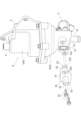
- FIG. 1 is a diagram schematically showing the flow of gas between the anode side of a fuel cell and a gas-liquid separator.
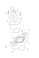
- FIG. 2 is a perspective view showing the gas-liquid separator and the heating member and holder in an assembled state.
- FIG. 2 is an exploded perspective view of a heating member, a heating element, and a holder.
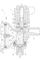
- FIG. 2 is a cross-sectional view of the lower part of the gas-liquid separator in a state where the on-off valve is closed.
- FIG. 2 is a sectional view of the lower part of the gas-liquid separator with the on-off valve open.
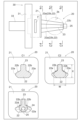
- 1 is a diagram showing a list of a heating element and cross sections of the heating element at locations indicated by a plurality of cross-section indicating lines.
- FIG. 3 is a side view showing a heating element of another embodiment (a).
- Figure 1 shows a fuel cell FC mounted on a fuel cell vehicle (FCV) and a gas-liquid separation system that separates water contained in anode off-gas (an example of water-containing gas) discharged from the anode side of the fuel cell FC.
- FCV fuel cell vehicle
- Device A is shown.
- a fuel cell FC generates electricity through an electrochemical reaction by supplying hydrogen gas as a fuel gas to the anode side and supplying air containing oxygen as an oxidizing gas to the cathode side. Only the anode side of the fuel cell FC is shown.
- the anode off-gas contains unreacted hydrogen gas
- the gas-liquid separator A guides the anode off-gas supplied from the introduction section 3 to the gas-liquid separation section 5, where it is separated from the anode off-gas.
- the water is separated, the separated water is stored in the water storage section 7, and the dry anode off-gas from which the water has been separated is sent out from the derivation section 4 to the reduction path L3.
- the anode off-gas thus sent to the reduction path L3 is supplied from the supply path L1 to the anode side of the fuel cell FC by the circulation pump P in the flow path of the reduction path L3, and unreacted hydrogen is used for power generation. .
- the gas-liquid separator A has a housing H consisting of an upper housing 1 and a lower housing 2, and the upper housing 1 and the lower housing 2 are connected by connecting their respective flanges to each other. and one are integrated to form a housing H having an internal space.
- the upper housing 1 is provided with a cylindrical introduction part 3 and a cylindrical outlet part 4 at the upper position, and is provided with a gas-liquid separation part 5 for separating water from the anode off-gas (water-containing gas) inside.
- the gas-liquid separation section 5 includes a plurality of vertical plate-shaped collision walls 5a that separate water by colliding with the anode off-gas supplied from the introduction section 3. Further, the dry anode off-gas that has passed through the gas-liquid separation section 5 is discharged from the outlet section 4.
- the lower housing 2 includes an open space 6 that allows the water separated by the gas-liquid separation section 5 to fall, a water storage section 7 that stores the water that has fallen through the open space 6, and an upper side of the water storage section 7 that stores the water.
- a filter unit 8 is provided to remove dust and the like contained in the filter.
- the lower portion of the lower housing 2 has a plurality of funnel-shaped inner surfaces 2a that taper downward, and the filter unit 8 is disposed at a position adjacent to the upper side of the funnel-shaped inner surface 2a at the lowest end. be done. Further, a cylindrical inner surface 2b that is circular in plan view is formed at a position continuous to the lower side of the funnel-shaped inner surface 2a at the lowest end.
- a water storage section 7 is constituted by a space surrounded by the funnel-shaped inner surface 2a at the lowermost end and a space surrounded by the cylindrical inner surface 2b. Note that the water storage portion 7 is not limited to a space that is circular in plan view, but may be rectangular, elliptical, or polygonal in plan view.
- the filter unit 8 includes a filter material 8b on the inner peripheral side of an annular frame 8a, and is fixed at the center to the support portion of the lower housing 2 with screws 8c. Thereby, dust contained in the water flowing into the water storage section 7 is removed by the filter material 8b.
- a block-shaped portion 10 is integrally formed at the lower end of the lower housing 2, and the water storage portion 7 described above is formed in this block-shaped portion 10.
- a concave portion 10a is formed in the block-shaped portion 10 in a horizontal position at a position communicating with the storage space of the water storage portion 7, and is recessed outward in the radial direction of the water storage portion 7 when viewed from above.
- a discharge hole path 11 is formed as a small-diameter orifice for laterally sending water stored in the water storage portion 7.
- the block-shaped portion 10 is formed with a cylindrical discharge portion 12 that communicates with the discharge hole passage 11 via the intra-block flow passage 10b and discharges water from the discharge hole passage 11 downward. Further, this block-shaped portion 10 is provided with an electromagnetic on-off valve V that controls the flow of water from the discharge hole path 11 to the discharge portion 12 .
- a heating member 20 is provided at the bottom of the water storage section 7 in a region where the water stored in the water storage section 7 flows into the discharge hole path 11.
- the heating member 20 is made of a material with high thermal conductivity, for example, an aluminum material.
- a heating element F is provided outside the water storage section 7 (outside the block-shaped section 10), which generates heat when energized and transmits the heat to the heating member 20.
- a through-hole portion 10c communicating with the space of the water storage portion 7 is formed on the opposite side of the block-shaped portion 10 from the discharge hole path 11 across the space of the water storage portion 7, and the heating member 20 is connected to the through-hole portion 10c. It is placed in the inserted state.
- the heating member 20 has a plate-shaped portion 21 integrally formed on the base end side, and a block-shaped portion is formed by a holder 30 disposed at a position covering the plate-shaped portion 21 and the heating element F. It is fixed at 10. The specific shape and fixing form of this heating member 20 will be described later.
- the discharge hole passage 11 is formed at a slightly higher position than the bottom wall 7a of the water storage portion 7, and a concave portion 10a is formed coaxially with this discharge hole passage 11.
- the discharge hole passage 11 is formed in a horizontal position so that the inner end communicates with the space of the water storage part 7 and the outer end communicates with the outside from one end of the block-shaped part 10. There is. Note that the end of the discharge hole path 11 on the discharge side opens into a truncated conical protrusion 10T.
- the discharge hole passage 11 and the discharge part 12 communicate with each other via the intra-block flow passage 10b of the block-shaped part 10, and by opening the on-off valve V, water from the discharge hole passage 11 flows into the block. It flows through the passage 10b to the discharge section 12 and is discharged.
- the on-off valve V includes a plunger 15 made of a magnetic material such as iron, an electromagnetic solenoid 16 disposed in an area surrounding the plunger 15, and an electromagnetic solenoid 16 that urges the plunger 15 in the projecting direction. It includes a spring 17 and a valve body 18 made of a membrane-like material such as rubber, which is disposed at a position to close the downstream end of the discharge hole path 11 and can be flexibly deformed between a closed position and an open position. ing.
- the heating member 20 is inserted into the bottom of the water storage portion 7 from the outside (outside the block-shaped portion 10 of the lower housing 2) with respect to the through-hole portion 10c.
- a heating element F is disposed on the outer surface of a plate-shaped portion 21 integrally formed on the base end side of the heating member 20, and a holder 30 is disposed at a position covering them.
- the heating member 20 and the holder 30 are fixed to the block-shaped portion 10 of the lower housing 2 with a plurality of bolts 34.
- the heating element F is placed in contact with the outer surface of the plate-shaped portion 21 (on the left side in FIGS. 4 and 5), and the heat generated by the heating element F is transmitted to the heating member 20.
- the heating element F is a PTC (Positive Temperature Coefficient) heater whose electrical resistance increases as the temperature rises.
- the heating member 20 is made of a material with high thermal conductivity, such as aluminum, and includes a plate-shaped portion 21, a heating main body portion 22 (an example of a main body portion), and a vertical wall portion 23 (an example of an upper wall portion). are integrally formed.
- the plate-shaped portion 21 is formed into a flat plate shape, and the heating main body portion 22 and the vertical wall portion 23 are integrally extended in a direction perpendicular to the plate surface of the plate-shaped portion 21 .
- the vertical wall portion 23 is formed so that the width in the lateral direction becomes slightly narrower as the tip approaches the discharge hole path 11 in plan view, and the height in side view becomes smaller. It is formed with a constant thickness in the direction.
- the heating main body portion 22 has a tapered shape that becomes thinner toward the distal end closer to the discharge hole path 11 along the extension direction in a plan view. In the region from near the center of the heating body part 22 to the tip side, at least a part of the heating body part 22 has a length in the vertical direction with respect to the maximum width W in the horizontal direction (maximum horizontal width of the heating body part 22).
- X (the vertical thickness of the heating member 20) is set to be large (see C2 in FIG. 6).
- the heating member 20, the heating element F, and the holder 30 are shown in an exploded state in a plan view.
- the cylindrical inner surface 2b of the water storage portion 7 formed in the lower housing 2 is shown with a two-dot chain line, so that the positional relationship between the heating member 20 and the water storage portion 7 in a plan view is shown. It shows.
- cross sections corresponding to the cross-section designation lines C1, C2, and C3 in the heating member 20 shown in the upper row are shown as C1 and C2 in the middle row, and as C3 in the lower row.
- the heating member 20 is fixed to the lower housing 2, and a portion including the heating main body portion 22 and the vertical wall portion 23 is disposed inside the water storage portion 7. As shown in the cross-sectional view of C2 in FIG. The dimensional relationship is set so that the length X becomes larger. The size relationship between the maximum width W and the length X does not hold true in all regions of the heating main body portion 22 and the vertical wall portion 23, but only in a portion thereof.
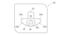
- the heating member 20 has wing-shaped portions 22a formed on the left and right portions of the heating main body portion 22, and a slope that slopes downward toward the outer side in the lateral direction on the upper surface of the left and right wing-shaped portions 22a.
- a surface 22b is formed.
- the cylindrical portion 22c extends from the tip of the heating body 22 in the direction in which the heating body 22 protrudes (extends in the opposite direction of the plate-shaped portion 21). is formed.
- a main discharge hole 24 is formed in this cylindrical portion 22c, and an introduction hole 25 communicating with the main discharge hole 24 is formed in the lower surface of the heating main body portion 22.
- the inner diameter of the main discharge hole 24 is larger than the inner diameter of the discharge hole passage 11 .
- the heating member 20 is placed in the lower housing 2 at a position where the cylindrical portion 22c of the heating main body portion 22 fits into the recessed portion 10a. Further, the end of the vertical wall portion 23 in the opposite direction from the plate-like portion 21 is arranged at a position close to the discharge hole path 11 . In this arrangement of the heating member 20, the main discharge hole 24 and the discharge hole path 11 are coaxial. Further, the main discharge hole 24 is formed in a region extending a predetermined distance from the tip of the heating main body portion 22 toward the plate-shaped portion 21, and the introduction hole 25 communicates with the main discharge hole 24.
- a gap shown in FIGS. 4 and 5 is formed between the lower surface of the heating main body part 22 and the bottom wall 7a of the water storage part 7. This gap is set to such a thickness that even if the water is frozen, by reducing the thickness of the frozen part, it can be quickly thawed by the heat applied from the heating member 20, and the water can flow. ing.
- the holder 30 is made of an insulating resin material and has a cover portion 31, a pair of connecting portions 32, and a connector portion 33 integrally formed.
- the cover part 31 is configured to accommodate the plate-shaped part 21 of the heating member 20 and to be able to come into contact with the outer surface of the block-shaped part 10 .
- the connecting portion 32 is integrally formed on the outer edge of the cover portion 31, and has a bolt insertion hole 32a formed therein.
- the connector portion 33 includes a pair of electrodes 33a inside a cylindrical connector space.
- the heating member 20 when the heating member 20 is attached to the lower housing 2, the heating member 20 is inserted into the internal space of the water storage portion 7 from the through hole portion 10c of the block-shaped portion 10, as described above.
- the heating element F is arranged on the outer surface of the plate-shaped part 21 of the heating member 20, the cover part 31 is arranged so as to overlap the plate-shaped part 21 and the heating element F, and the bolt 34 is inserted into the bolt insertion hole 32a of the connecting part 32.
- the holder 30 is fixed by being inserted therethrough and screwed into the female threaded portion of the block-shaped portion 10 .
- a ring of rubber or resin is formed between the outer surface of the block-shaped part 10 and the plate-shaped part 21, and between the plate-shaped part 21 and the cover part 31.
- a seal body 27 is arranged.
- the heating element F is brought into close contact with the outer surface of the plate-shaped portion 21, and a conductive portion for supplying current to the heating element F from the electrode 33a of the connector portion 33 is formed.
- the fuel cell vehicle includes a control unit that controls the on-off valve V and controls the current supplied to the heating element F.
- This control section calculates the amount of water generated by power generation from the amount of power generated by the fuel cell during driving, estimates the amount of water stored in the water storage section 7, and every time the estimated amount of water reaches the set amount.
- opening the on-off valve V for a set time the water in the water storage section 7 is controlled to be discharged from the discharge hole path 11.
- control mode instead of such a control mode, a water level sensor that detects the water surface position is provided in order to measure the amount of water stored in the water storage section 7, and each time the water level detected by this water level sensor reaches a set value, Alternatively, the control mode may be set so that the on-off valve V is opened to discharge the water stored in the water storage section 7.
- the control unit is configured to prevent heat generation before starting to drive. Freezing is eliminated by supplying current to the body F to raise the temperature of the heating member 20. In order to eliminate freezing in this way, scavenging is performed by opening the on-off valve V and setting a predetermined air stoichiometric ratio in the fuel cell FC to operate (generate power).
- the temperature of the heating member 20 increases by supplying current to the heating element F, thereby increasing the temperature of the space between the lower surface of the heating main body 22 and the bottom wall 7a of the water storage section 7. , the temperature of the outer surface of the heating main body portion 22 or the vertical wall portion 23 is increased. This will thaw the ice if these parts are frozen, increase the temperature of the water if the temperature has dropped even if these parts do not freeze, and allow the thawed water to drain into the drain hole. It will be discharged from path 11.
- the heating member 20 when installing the heating member 20, the heating member 20 is inserted from the outside into the through hole 10c of the block-shaped part 10 of the lower housing 2, and the heating element F is arranged on the outer surface of the plate-shaped part 21.
- the heating member 20 can be easily attached and maintenance is not required.
- the heating element F since the heating element F is placed outside the lower housing 2, the problem of water coming into contact with the heating element F does not occur, and the configuration for electrical insulation is simplified, allowing for leakage. It will not cause short circuit or short circuit.
- the heating member 20 has a heating main body portion 22 and a vertical wall portion 23 that are integrally formed and are disposed inside the space of the water storage portion 7.
- the wide outer surface of the casing is brought into contact with water to enable efficient thawing.
- the vertical wall portion 23 allows the ice to be thawed even when the water storage portion 7 is frozen at a relatively high water level.
- a gap is formed between the lower surface of the heating main body part 22 and the bottom wall 7a of the water storage part 7, a flow of water is created in this gap, and a part of the water in this gap is transferred from the introduction hole 25.
- the temperature of the water flowing into the main discharge hole 24 can be increased.
- the heating member 20 is arranged such that a cylindrical portion 22c is fitted into the recessed portion 10a, and this cylindrical portion 22c is close to the discharge hole passage 11 formed in an orifice shape. Therefore, even if the discharge hole passage 11 is frozen, it can be thawed by the heat from the cylindrical portion 22c.
- a main discharge hole 24 is arranged in the cylindrical portion 22c coaxially with the discharge hole path 11, and in order to supply water to the main discharge hole 24 from the introduction hole 25, water is heated by the heating member 20. The water is sent out from the main discharge hole 24, and the discharge hole path 11 can be thawed efficiently.
- the heating member 20 forms a pair of wing-shaped parts 22a that expand outward on both sides in the lateral direction with the lateral center as a reference at the lower part of the heating main body part 22,
- the pair of wing-like parts 22a are formed so that the width decreases toward the tip side (the side where the cylindrical part 22c is located), so that the water in the water storage part 7 can smoothly flow into the discharge hole path 11. becomes possible.
- the lower surface of the wing-shaped portion 22a may include a U-shaped inclined surface 22d that slopes upward toward the outer side in the lateral direction.
- the upper surface of the wing-shaped portion 22a may be in a horizontal position, or the outer side in the width direction may be in an upwardly raised position. That is, the shape of the wing-shaped portion 22a may be any shape as long as a gap is formed between the lower surface of the heating main body portion 22 and the bottom wall 7a of the water storage portion 7.
- a portion of the heating member 20 may not have a fixed cross-sectional shape, such as a trapezoid or a rectangle, so that the maximum width in the horizontal direction is greater than the length in the vertical direction. Further, in order to increase the surface area of the heating member 20 and improve the efficiency of heat exchange with water, a groove-like portion or an uneven surface may be formed on the surface. Furthermore, all of the heating members 20 may be configured such that the maximum width in the horizontal direction is larger than the length in the vertical direction.
- Characteristic configurations of the gas-liquid separator (A) according to the present disclosure include a housing (H) to which water-containing gas is supplied, and a gas-liquid separator disposed above the housing (H) to separate water from the water-containing gas. part (5), a water storage part (7) which is arranged at the lower part of the housing (H) and stores water separated from the water-containing gas by the gas-liquid separation part (5), and a water storage part (7) of the housing (H).
- a discharge hole path (11) is disposed at the bottom and discharges the water sent from the water storage section (7) to the outside of the housing (H), and a discharge hole path (11) that protrudes into the water storage section (7) and discharges water sent from the water storage section (7) to the outside of the housing (H).
- the heating member (20) has a heating member (20) whose temperature increases due to the heat transferred from the heating element (F) which generates heat when energized. 7)
- the main body part (22) protrudes toward the discharge hole path (11) at the bottom of the water storage part (7), and the upper part protrudes upward from the main body part (22). The point is that it has a wall portion (23).
- the temperature rise of the heating member (20) causes the water in the water storage section (7) to flow into the discharge hole path (11) at the bottom of the water storage section (7). Thawing can be achieved by applying heat directly to the frozen portion of the flowing region.
- the heating member (20) has a main body (22) and an upper wall (23) projecting upward from the main body (22), water flowing into the water storage part (7) is transmitted.
- the temperature of the water storage part (7) is raised by bringing the area with a large thermal area (mainly the upper wall part (23)) into contact with each other, and even if the water level freezing in the water storage part (7) is relatively high, freezing can be removed. .
- a gas-liquid separator (A) has been constructed which, although having a simple structure, can eliminate freezing at the bottom of the gas-liquid separator (A) and quickly discharge water from the bottom.
- the upper wall portion (23) extends from the position where the heating element (F) is provided to a position close to the discharge hole path (11). It is okay to exist.
- the end of the upper wall (23) in the extending direction is in a positional relationship close to the discharge hole passage (11), and the heat transferred from this end causes the heat to stay in the vicinity of the discharge hole passage (11). Allows ice to thaw.
- the heating member (20) has a length (X) in the vertical direction on the side of the discharge hole path (11). It may be larger than the maximum width (W) in the direction.
- the length (X) in the vertical direction of the heating member (20) is larger than the maximum width (W) in the horizontal direction on the side of the discharge hole passage (11), It becomes possible to secure an area with a large heat transfer area for the water flowing into the area. As a result, not only the storage capacity of the water storage section (7) becomes large and the device becomes more compact, but also the temperature of the water storage section (7) can be quickly raised to eliminate freezing.
- the main body (22) has a main body (22) on both sides in the lateral direction based on the lateral center. 22) may be provided with a wing-shaped portion (22a) whose width decreases from the base end to which the air conditioner 22) is fixed toward the distal end close to the discharge hole path (11).
- the discharge hole path (11) can be thawed by heat from the wide surface of the wing-shaped portion (22a). do.
- the width of the wing-shaped portion (22a) decreases as the tip approaches the discharge hole passage (11)
- the thermal conductivity improves as the tip approaches, making it possible to effectively defrost the discharge hole passage (11). Not only is this possible, but when the water heated by the heating member (20) flows into the discharge hole path (11), the resistance acting on the water from the wing-shaped portion (22a) is reduced to enable smooth flow. .
- the upper surface of the wing-shaped portion (22a) may be inclined downward toward the outer side in the lateral direction.
- the water flowing into the water storage part (7) flows outward on the upper surface of the wing part (22a), thereby reducing the resistance acting on the water from the wing part (22a) and making it possible to flow without stagnation.
- the temperature of the heating member (20) is raised in a state where the water storage portion (7) is frozen, rapid thawing is achieved by transmitting heat from the wide surface of the wing-shaped portion (22a).
- the lower surface of the wing-shaped portion (22a) may be inclined upward toward the outer side in the lateral direction.
- the present disclosure can be used in a gas-liquid separator.
- Gas-liquid separation section 7 Water storage section 11 Discharge hole path 20 Heating member 22 Heating main body section (main body section) 22a Wing-shaped portion 23 Vertical wall portion (upper wall portion) A Gas-liquid separator F Heating element H Housing W Width X Thickness
Abstract
This gas-liquid separator is provided with: a housing; a gas-liquid separation unit which separates water from a water-containing gas in the upper part of the housing; a water storage unit which stores water that has been separated from the water-containing gas in the lower part of the housing; a discharge path which discharges the water in the water storage unit to the outside of the housing; and a heating member, the temperature of which is increased by heat that is transferred from a heating element F that generates heat by means of electrical conduction, and which protrudes into the water storage unit so as to be arranged in a region where the water flows into the discharge path. The heating member comprises a main body part which protrudes towards the discharge path at the bottom of the water storage unit, and an upper wall part which upwardly protrudes from the main body part in a state where the heating element F is arranged on the outer side of the water storage unit.
Description
本開示は、気液分離器に関する。
The present disclosure relates to a gas-liquid separator.
特許文献1には、燃料電池から排出される排出ガス通路を通る水の凍結を抑制するために、排ガス通路内に凍結抑制剤を循環させるための凍結抑制剤循環部を備えた燃料電池システムが記載されている。
Patent Document 1 discloses a fuel cell system equipped with a freeze suppressant circulation unit for circulating a freeze suppressant in the exhaust gas passage in order to suppress freezing of water passing through the exhaust gas passage discharged from the fuel cell. Are listed.
この特許文献1では、酸化オフガス通路における生成水の凍結を抑制するため、エチレングリコールを利用した凍結抑制剤を酸化オフガス通路に注入し、酸化オフガス通路の下流側部分において、加熱により生成水から凍結抑制剤を分離して回収し、再利用する構成が記載されている。
In Patent Document 1, in order to suppress the freezing of produced water in the oxidation off-gas passage, a freezing inhibitor using ethylene glycol is injected into the oxidation off-gas passage, and the produced water is frozen by heating in the downstream part of the oxidation off-gas passage. A configuration is described in which the inhibitor is separated, recovered, and reused.
特許文献2には、燃料電池スタックから排出された燃料オフガスから気液分離器で分離された水を流体導入部から弁装置に送り、この弁装置の制御によって排水する構成を備え、流体導入部の内孔に加熱装置を配置した燃料電池システムが記載されている。
Patent Document 2 discloses a configuration in which water separated from fuel off-gas discharged from a fuel cell stack by a gas-liquid separator is sent from a fluid introduction part to a valve device, and is drained under control of the valve device. A fuel cell system is described in which a heating device is arranged in the inner hole of the fuel cell system.
この特許文献2では、加熱装置として電力供給によって発熱するPTCヒータが、筒状のカバー部本体の端部に配置され、カバー部本体の内部の水が凍結した場合にPTCヒータの発熱により解凍を行う点が記載されている。
In Patent Document 2, a PTC heater that generates heat by power supply as a heating device is arranged at the end of a cylindrical cover main body, and when water inside the cover main body freezes, the heat generated by the PTC heater thaws the water. It describes what to do.
特許文献3には、アノード電極から排出される燃料排ガスを気液分離器において気体と液体とに分離し、液体を排出する排出流路に圧縮酸化剤ガスを導き、圧縮酸化剤ガスの熱によって、排出流路及びその近傍の加熱を行う燃料電池システムが記載されている。
Patent Document 3 discloses that fuel exhaust gas discharged from an anode electrode is separated into gas and liquid in a gas-liquid separator, compressed oxidizing gas is introduced into a discharge passageway for discharging the liquid, and the compressed oxidizing gas is heated by the heat of the compressed oxidizing gas. , a fuel cell system that heats the exhaust flow path and its vicinity is described.
この特許文献3では、排出流路に導かれる圧縮酸化剤ガスを加熱するヒータユニットも記載されている。
This Patent Document 3 also describes a heater unit that heats compressed oxidant gas guided to the discharge flow path.
燃料電池を用いた発電システムでは、燃料オフガス(アノードオフガス)に含まれる燃料ガスを燃料電池で再利用するために、気液分離器によって水を除去した燃料オフガスを、燃料ガスの供給流路に戻すことが行われている。
In power generation systems using fuel cells, in order to reuse the fuel gas contained in the fuel off-gas (anode off-gas) in the fuel cell, the fuel off-gas from which water has been removed by a gas-liquid separator is added to the fuel gas supply flow path. It is being brought back.
特許文献2に記載されるように、気液分離器は、分離された水を底部に一時的に貯留し、所定のタイミングでバルブを開放することにより貯留した水を外部に排出する形態で使用されている。
As described in Patent Document 2, a gas-liquid separator is used in a form that temporarily stores separated water at the bottom and discharges the stored water to the outside by opening a valve at a predetermined timing. has been done.
このように燃料電池で発電された電力によって走行する燃料電池車は、寒冷地で走行した際や、寒冷地で駐車した際には、気液分離器の底部に貯留されている水が凍結し、排出が困難になるおそれもある。尚、燃料電池車は、寒冷地で駐車する場合には、燃料電池の発電停止時に、気液分離器に貯留された水を排出する制御が行われるものの、燃料電池のアノード側に残留する水滴や、アノードオフガスが流れる経路の水滴が気液分離器に流れ込み、凍結するおそれがあるので、何らかの対策が必要である。
When a fuel cell vehicle runs on electricity generated by a fuel cell, or is parked in a cold region, the water stored at the bottom of the gas-liquid separator may freeze. , it may become difficult to discharge. When a fuel cell vehicle is parked in a cold region, water droplets remaining on the anode side of the fuel cell are controlled to be discharged when the fuel cell stops generating electricity. Also, there is a risk that water droplets in the path through which the anode off-gas flows may flow into the gas-liquid separator and freeze, so some kind of countermeasure is required.
このような不都合を解消するため、特許文献1に記載される凍結抑制剤を用いて凍結を防止することも考えられる、しかしながら、特許文献1に記載されるようにヒータによる加熱によって水を蒸発させ、水と凍結抑制剤との分離を図る構成では、ヒータで消費される電流が大きくなると共に、凍結抑制剤を回収するための機構が複雑化することが考えられる。
In order to eliminate such inconveniences, it is conceivable to prevent freezing using a freezing inhibitor described in Patent Document 1. However, as described in Patent Document 1, water is evaporated by heating with a heater. In a configuration that attempts to separate the water and the anti-freeze agent, the electric current consumed by the heater increases and the mechanism for recovering the anti-freeze agent may become complicated.
また、特許文献2に記載されるように、PTCヒータを用いる構成では、通電によるPTCヒータの熱により、弁装置の加熱も可能となる。しかしながら、この構成ではPTCヒータと弁装置とが離間しており、弁装置の近傍の凍結の解消に時間が掛かることも想像できた。尚、特許文献2の構成においてPTCヒータを弁装置に近接して配置した場合には、PCTヒータが水の流れを妨げる不都合を招くことも考えられる。
Furthermore, as described in Patent Document 2, in a configuration using a PTC heater, the valve device can also be heated by the heat of the PTC heater due to energization. However, in this configuration, the PTC heater and the valve device are separated from each other, and it could be imagined that it would take time to defreeze the area near the valve device. In addition, when the PTC heater is arranged close to the valve device in the configuration of Patent Document 2, it is conceivable that the PCT heater may impede the flow of water.
更に、特許文献3に記載されるように、圧縮酸化剤ガスの供給により気液分離器の液体排出口の凍結を解消する構成を備えることも考えられるが、この特許文献3の構成は、専用のガス流路を必要とするため、構成の複雑化が懸念される。
Furthermore, as described in Patent Document 3, it is possible to provide a configuration for unfreezing the liquid outlet of the gas-liquid separator by supplying compressed oxidant gas, but the configuration of Patent Document 3 is Since this method requires several gas flow paths, there is a concern that the configuration will become complicated.
このような理由から、単純な構成でありながら気液分離器の底部での凍結を解消し、底部の水の排出を迅速に行える気液分離器が求められている。
For these reasons, there is a need for a gas-liquid separator that has a simple configuration but can eliminate freezing at the bottom of the gas-liquid separator and quickly discharge water from the bottom.
本開示に係る気液分離器の特徴構成は、含水ガスが供給されるハウジングと、前記ハウジングの上部に配置され前記含水ガスから水を分離する気液分離部と、前記ハウジングの下部に配置され前記気液分離部によって前記含水ガスから分離した水を貯留する貯水部と、前記ハウジングの前記貯水部の下部に配置され、前記貯水部より送られた前記水を前記ハウジングの外部に排出する排出孔路と、前記貯水部の中へ突出し、前記水が前記排出孔路に流れる領域に配置され、通電により発熱する発熱体から伝えられる熱により温度が上昇する加熱部材と備え、前記加熱部材は、前記発熱体が前記貯水部よりも外部に配置された状態で、前記貯水部の底部で前記排出孔路の側へと突出する本体部と、当該本体部から上方へ突出する上壁部とを有している点にある。
A characteristic configuration of the gas-liquid separator according to the present disclosure includes: a housing to which a hydrous gas is supplied; a gas-liquid separator disposed in an upper part of the housing to separate water from the hydrous gas; and a gas-liquid separator disposed in a lower part of the housing. a water storage section that stores water separated from the water-containing gas by the gas-liquid separation section; and a discharge disposed below the water storage section of the housing to discharge the water sent from the water storage section to the outside of the housing. and a heating member that protrudes into the water storage part and is disposed in a region where the water flows into the discharge hole, and whose temperature increases due to heat transmitted from a heating element that generates heat when energized, the heating member , a main body part that projects toward the discharge hole path at the bottom of the water storage part, and an upper wall part that projects upward from the main body part, with the heating element disposed outside the water storage part. The point is that it has the following.
本構成によると、貯水部の水が凍結する状況において加熱部材の温度上昇により、貯水部の底部において貯水部の水が排出孔路に流れる領域の凍結部分に直接的に熱を作用させて解凍を行える。また、加熱部材が本体部と、本体部から上方に突出する上壁部とを有しているため、貯水部に流れ込む水に対し伝熱面積の大きい領域(主に上壁部)を接触させる形態で貯水部の温度を上昇させ、貯水部で凍結する水位が比較的高くても凍結を解消できる。更に、本構成では、貯水部の外部に配置された発熱体の熱が加熱部材に伝えられるため、発熱体に貯水部の水が接触する不都合を招くことがなく、電気的な絶縁を確実に行える。従って、単純な構成でありながら気液分離器の底部での凍結を解消し、底部の水の排出を迅速に行える気液分離器が構成された。
According to this configuration, when the water in the water storage part freezes, the temperature of the heating member increases, and heat is applied directly to the frozen part of the area where the water in the water storage part flows to the discharge hole path at the bottom of the water storage part to thaw it. can be done. In addition, since the heating member has a main body and an upper wall that protrudes upward from the main body, a region with a large heat transfer area (mainly the upper wall) is brought into contact with the water flowing into the water storage section. This feature increases the temperature of the water storage area, making it possible to unfreeze the water even if the frozen water level in the storage area is relatively high. Furthermore, with this configuration, the heat of the heating element placed outside the water storage section is transferred to the heating member, so there is no problem of water in the water storage section coming into contact with the heating element, and electrical insulation is ensured. I can do it. Therefore, a gas-liquid separator has been constructed which, although having a simple structure, can eliminate freezing at the bottom of the gas-liquid separator and quickly discharge water from the bottom.
以下、本開示の実施形態を図面に基づいて説明する。
〔基本構成〕
図1には、燃料電池車(FCV)に搭載される燃料電池FC、及び、この燃料電池FCのアノード側から排出されるアノードオフガス(含水ガスの一例)に含まれる水を分離する気液分離器Aが示されている。 Embodiments of the present disclosure will be described below based on the drawings.
[Basic configuration]
Figure 1 shows a fuel cell FC mounted on a fuel cell vehicle (FCV) and a gas-liquid separation system that separates water contained in anode off-gas (an example of water-containing gas) discharged from the anode side of the fuel cell FC. Device A is shown.
燃料電池FCは、燃料ガスとしての水素ガスがアノード側に供給され、酸化ガスとしての酸素を含む空気がカソード側に供給されることで電気化学反応により発電するものであるが、同図には燃料電池FCのアノード側だけを示している。
A fuel cell FC generates electricity through an electrochemical reaction by supplying hydrogen gas as a fuel gas to the anode side and supplying air containing oxygen as an oxidizing gas to the cathode side. Only the anode side of the fuel cell FC is shown.
図1に示すように、燃料電池FCを有する発電システムでは、燃料タンクTに貯留した水素ガスを供給経路L1から燃料電池FCのアノード側に供給し、燃料電池FCのアノード側から排出されたアノードオフガスを排出経路L2から気液分離器Aの導入部3に供給する。
As shown in FIG. 1, in a power generation system having a fuel cell FC, hydrogen gas stored in a fuel tank T is supplied to the anode side of the fuel cell FC from a supply path L1, and hydrogen gas is discharged from the anode side of the fuel cell FC. The off-gas is supplied to the introduction section 3 of the gas-liquid separator A from the exhaust path L2.
アノードオフガスは、未反応の水素ガスを含むものであり、気液分離器Aは、導入部3から供給されたアノードオフガスを気液分離部5に導き、この気液分離部5においてアノードオフガスから水を分離し、分離した水を貯水部7に貯留し、水が分離した乾燥状態のアノードオフガスを導出部4から還元経路L3に送り出す。このように還元経路L3に送り出されたアノードオフガスは、還元経路L3の流路中の循環ポンプPによって供給経路L1から燃料電池FCのアノード側に供給され、未反応の水素が発電に利用される。
The anode off-gas contains unreacted hydrogen gas, and the gas-liquid separator A guides the anode off-gas supplied from the introduction section 3 to the gas-liquid separation section 5, where it is separated from the anode off-gas. The water is separated, the separated water is stored in the water storage section 7, and the dry anode off-gas from which the water has been separated is sent out from the derivation section 4 to the reduction path L3. The anode off-gas thus sent to the reduction path L3 is supplied from the supply path L1 to the anode side of the fuel cell FC by the circulation pump P in the flow path of the reduction path L3, and unreacted hydrogen is used for power generation. .
〔気液分離器〕
図1、図2に示すように、気液分離器Aは、上部ハウジング1と下部ハウジング2とで成るハウジングHを有し、夫々のフランジ部を互いに連結することによって上部ハウジング1と下部ハウジング2と一が体化され、内部空間を有するハウジングHが構成される。 [Gas-liquid separator]
As shown in FIGS. 1 and 2, the gas-liquid separator A has a housing H consisting of anupper housing 1 and a lower housing 2, and the upper housing 1 and the lower housing 2 are connected by connecting their respective flanges to each other. and one are integrated to form a housing H having an internal space.
図1、図2に示すように、気液分離器Aは、上部ハウジング1と下部ハウジング2とで成るハウジングHを有し、夫々のフランジ部を互いに連結することによって上部ハウジング1と下部ハウジング2と一が体化され、内部空間を有するハウジングHが構成される。 [Gas-liquid separator]
As shown in FIGS. 1 and 2, the gas-liquid separator A has a housing H consisting of an
上部ハウジング1は、上部位置に筒状の導入部3と、筒状の導出部4とを備え、内部にアノードオフガス(含水ガス)から水を分離する気液分離部5を備えている。気液分離部5は、導入部3から供給されるアノードオフガスが衝突することにより、水を分離する複数の縦板状の衝突壁5aを備えている。また、この気液分離部5を通過した乾燥状態のアノードオフガスが導出部4から排出される。
The upper housing 1 is provided with a cylindrical introduction part 3 and a cylindrical outlet part 4 at the upper position, and is provided with a gas-liquid separation part 5 for separating water from the anode off-gas (water-containing gas) inside. The gas-liquid separation section 5 includes a plurality of vertical plate-shaped collision walls 5a that separate water by colliding with the anode off-gas supplied from the introduction section 3. Further, the dry anode off-gas that has passed through the gas-liquid separation section 5 is discharged from the outlet section 4.
下部ハウジング2は、気液分離部5で分離された水の落下を可能にする開放空間6と、この開放空間6を落下した水を貯留する貯水部7と、貯水部7の上側において、水に含まれる塵埃等を除去するフィルタユニット8とを備えている。
The lower housing 2 includes an open space 6 that allows the water separated by the gas-liquid separation section 5 to fall, a water storage section 7 that stores the water that has fallen through the open space 6, and an upper side of the water storage section 7 that stores the water. A filter unit 8 is provided to remove dust and the like contained in the filter.
図4、図5に示すように、下部ハウジング2の下部は、下窄まりの複数の漏斗状内面2aを有し、最下端の漏斗状内面2aの上側に隣接する位置にフィルタユニット8が配置される。また、最下端の漏斗状内面2aの下側に連なる位置に、平面視で円形となる円筒状内面2bが形成されている。
As shown in FIGS. 4 and 5, the lower portion of the lower housing 2 has a plurality of funnel-shaped inner surfaces 2a that taper downward, and the filter unit 8 is disposed at a position adjacent to the upper side of the funnel-shaped inner surface 2a at the lowest end. be done. Further, a cylindrical inner surface 2b that is circular in plan view is formed at a position continuous to the lower side of the funnel-shaped inner surface 2a at the lowest end.
この最下端の漏斗状内面2aに取り囲まれる空間と、円筒状内面2bに取り囲まれる空間とで貯水部7が構成されている。尚、貯水部7は、平面視で円形となる空間に限るものではなく、平面視で矩形、楕円形、多角形であっても良い。
A water storage section 7 is constituted by a space surrounded by the funnel-shaped inner surface 2a at the lowermost end and a space surrounded by the cylindrical inner surface 2b. Note that the water storage portion 7 is not limited to a space that is circular in plan view, but may be rectangular, elliptical, or polygonal in plan view.
フィルタユニット8は、環状フレーム8aの内周側にフィルタ材8bを備え、中央が下部ハウジング2の支持部に対しビス8cによって固定されている。これにより貯水部7に流れ込む水に含まれる塵埃がフィルタ材8bによって除去される。
The filter unit 8 includes a filter material 8b on the inner peripheral side of an annular frame 8a, and is fixed at the center to the support portion of the lower housing 2 with screws 8c. Thereby, dust contained in the water flowing into the water storage section 7 is removed by the filter material 8b.
図4、図5に示すように、下部ハウジング2の下端部に、ブロック状部10が一体的に形成され、このブロック状部10に対し、前述した貯水部7が形成されている。
As shown in FIGS. 4 and 5, a block-shaped portion 10 is integrally formed at the lower end of the lower housing 2, and the water storage portion 7 described above is formed in this block-shaped portion 10.
ブロック状部10には、貯水部7の貯留空間に連通する位置に水平姿勢で、平面視で貯水部7の径方向の外方に窪む凹状部10aが形成されている。この凹状部10aの外端位置に、貯水部7に貯留された水を横方向に送る排出孔路11が小径のオリフィスとして形成されている。
A concave portion 10a is formed in the block-shaped portion 10 in a horizontal position at a position communicating with the storage space of the water storage portion 7, and is recessed outward in the radial direction of the water storage portion 7 when viewed from above. At the outer end of this concave portion 10a, a discharge hole path 11 is formed as a small-diameter orifice for laterally sending water stored in the water storage portion 7.
ブロック状部10には、排出孔路11とブロック内流路10bを介して連通し、排出孔路11からの水を下方に排出する筒状の排出部12が形成されている。更に、このブロック状部10に対し、排出孔路11から排出部12に流れる水の流れを制御する電磁型の開閉弁Vが備えられている。
The block-shaped portion 10 is formed with a cylindrical discharge portion 12 that communicates with the discharge hole passage 11 via the intra-block flow passage 10b and discharges water from the discharge hole passage 11 downward. Further, this block-shaped portion 10 is provided with an electromagnetic on-off valve V that controls the flow of water from the discharge hole path 11 to the discharge portion 12 .
図1、図4、図5に示すように、貯水部7の底部において、この貯水部7に貯留された水が排出孔路11に流れる領域に加熱部材20を備えている。この加熱部材20は、熱伝導率が高い材料、例えば一例としてアルミニウム材で構成されている。また、貯水部7の外部(ブロック状部10の外部)に対し、通電により発熱し加熱部材20に熱を伝える発熱体Fを備えている。
As shown in FIGS. 1, 4, and 5, a heating member 20 is provided at the bottom of the water storage section 7 in a region where the water stored in the water storage section 7 flows into the discharge hole path 11. The heating member 20 is made of a material with high thermal conductivity, for example, an aluminum material. Further, a heating element F is provided outside the water storage section 7 (outside the block-shaped section 10), which generates heat when energized and transmits the heat to the heating member 20.
ブロック状部10のうち、貯水部7の空間を挟んで排出孔路11と反対側に、貯水部7の空間に連通する貫通孔部10cが形成され、加熱部材20は、貫通孔部10cに挿入された状態で配置されている。加熱部材20は図3、図6に示すように基端側にプレート状部21が一体形成され、このプレート状部21と、発熱体Fとを覆う位置に配置されるホルダ30によってブロック状部10に固定されている。この加熱部材20の具体的な形状や固定形態は後述する。
A through-hole portion 10c communicating with the space of the water storage portion 7 is formed on the opposite side of the block-shaped portion 10 from the discharge hole path 11 across the space of the water storage portion 7, and the heating member 20 is connected to the through-hole portion 10c. It is placed in the inserted state. As shown in FIGS. 3 and 6, the heating member 20 has a plate-shaped portion 21 integrally formed on the base end side, and a block-shaped portion is formed by a holder 30 disposed at a position covering the plate-shaped portion 21 and the heating element F. It is fixed at 10. The specific shape and fixing form of this heating member 20 will be described later.
図4、図5に示すように、排出孔路11は、貯水部7の底壁7aから僅かに高い位置に形成され、この排出孔路11と同軸芯で凹状部10aが形成されている。前述したように、排出孔路11は、内端部が貯水部7の空間に連通し、外端部がブロック状部10の一方の端部から外部に連通するように水平姿勢で形成されている。尚、排出孔路11の排出側の端部は、円錐台状の突出部10Tに開口している。
As shown in FIGS. 4 and 5, the discharge hole passage 11 is formed at a slightly higher position than the bottom wall 7a of the water storage portion 7, and a concave portion 10a is formed coaxially with this discharge hole passage 11. As described above, the discharge hole passage 11 is formed in a horizontal position so that the inner end communicates with the space of the water storage part 7 and the outer end communicates with the outside from one end of the block-shaped part 10. There is. Note that the end of the discharge hole path 11 on the discharge side opens into a truncated conical protrusion 10T.
排出孔路11と、排出部12とは、ブロック状部10のブロック内流路10bを介して連通しており、開閉弁Vを開放することにより、排出孔路11からの水がブロック内流路10bを介して排出部12に流れることで排出される。
The discharge hole passage 11 and the discharge part 12 communicate with each other via the intra-block flow passage 10b of the block-shaped part 10, and by opening the on-off valve V, water from the discharge hole passage 11 flows into the block. It flows through the passage 10b to the discharge section 12 and is discharged.
〔開閉弁〕
図4、図5に示すように、開閉弁Vは、鉄材等の磁性体で成るプランジャ15と、このプランジャ15を取り囲む領域に配置された電磁ソレノイド16と、プランジャ15を突出方向に付勢するスプリング17と、排出孔路11の下流側の端部を閉塞する位置に配置され、閉塞位置と開放位置との間で柔軟に変形し得るゴム等の膜状素材から成る弁体18とを備えている。 [On-off valve]
As shown in FIGS. 4 and 5, the on-off valve V includes aplunger 15 made of a magnetic material such as iron, an electromagnetic solenoid 16 disposed in an area surrounding the plunger 15, and an electromagnetic solenoid 16 that urges the plunger 15 in the projecting direction. It includes a spring 17 and a valve body 18 made of a membrane-like material such as rubber, which is disposed at a position to close the downstream end of the discharge hole path 11 and can be flexibly deformed between a closed position and an open position. ing.
図4、図5に示すように、開閉弁Vは、鉄材等の磁性体で成るプランジャ15と、このプランジャ15を取り囲む領域に配置された電磁ソレノイド16と、プランジャ15を突出方向に付勢するスプリング17と、排出孔路11の下流側の端部を閉塞する位置に配置され、閉塞位置と開放位置との間で柔軟に変形し得るゴム等の膜状素材から成る弁体18とを備えている。 [On-off valve]
As shown in FIGS. 4 and 5, the on-off valve V includes a
開閉弁Vは、電磁ソレノイド16が非通電状態にある場合には、図4に示すようにスプリング17の付勢力によりプランジャ15が突出し、弁体18が、排出孔路11の外端位置を閉塞する位置に保持される。これに対し、電磁ソレノイド16が通電状態にある場合には、図5に示すようにスプリング17の付勢力に抗してプランジャ15が排出孔路11の外端部から離間する方向にシフトし、弁体18が開放位置に作動する。
In the on-off valve V, when the electromagnetic solenoid 16 is in a de-energized state, the plunger 15 protrudes due to the biasing force of the spring 17, as shown in FIG. is held in the desired position. On the other hand, when the electromagnetic solenoid 16 is energized, the plunger 15 is shifted away from the outer end of the discharge hole passage 11 against the biasing force of the spring 17, as shown in FIG. Valve body 18 is actuated to the open position.
〔加熱部材〕
気液分離器Aは、低温環境において燃料電池の発電を停止して燃料電池車を駐車した場合に、貯水部7から排出孔路11に亘る領域に残留する水が凍結することもある。また、気液分離器Aは、低温の環境で燃料電池車を走行させる状況において貯水部7の水が凍結することもある。このような凍結を解消するため、図1、図4、図5に示すように、加熱部材20を貯水部7の底部に収容する形態で備えている。 [Heating member]
In the gas-liquid separator A, when power generation by the fuel cell is stopped and the fuel cell vehicle is parked in a low-temperature environment, water remaining in the area extending from thewater storage section 7 to the discharge hole path 11 may freeze. Further, in the gas-liquid separator A, water in the water storage section 7 may freeze when the fuel cell vehicle is driven in a low-temperature environment. In order to eliminate such freezing, as shown in FIGS. 1, 4, and 5, a heating member 20 is provided to be accommodated at the bottom of the water storage portion 7.
気液分離器Aは、低温環境において燃料電池の発電を停止して燃料電池車を駐車した場合に、貯水部7から排出孔路11に亘る領域に残留する水が凍結することもある。また、気液分離器Aは、低温の環境で燃料電池車を走行させる状況において貯水部7の水が凍結することもある。このような凍結を解消するため、図1、図4、図5に示すように、加熱部材20を貯水部7の底部に収容する形態で備えている。 [Heating member]
In the gas-liquid separator A, when power generation by the fuel cell is stopped and the fuel cell vehicle is parked in a low-temperature environment, water remaining in the area extending from the
図2、図3に示すように、加熱部材20は、貫通孔部10cに対し、外側(下部ハウジング2のブロック状部10の外側)から貯水部7の底部に挿入する形態で配置される。この加熱部材20の基端側に一体形成されたプレート状部21の外面には発熱体Fが配置され、これらを覆う位置にホルダ30が配置されている。加熱部材20とホルダ30は、複数のボルト34により下部ハウジング2のブロック状部10に固定される。
As shown in FIGS. 2 and 3, the heating member 20 is inserted into the bottom of the water storage portion 7 from the outside (outside the block-shaped portion 10 of the lower housing 2) with respect to the through-hole portion 10c. A heating element F is disposed on the outer surface of a plate-shaped portion 21 integrally formed on the base end side of the heating member 20, and a holder 30 is disposed at a position covering them. The heating member 20 and the holder 30 are fixed to the block-shaped portion 10 of the lower housing 2 with a plurality of bolts 34.
発熱体Fは、プレート状部21の外面側(図4,図5で左側)に接触状態で配置されており、この発熱体Fの発熱時の熱が加熱部材20に伝えられる。発熱体Fは、温度上昇に伴い電気抵抗が上昇する特性のPTC(Positive Temperature Coefficient)ヒータが用いられている。
The heating element F is placed in contact with the outer surface of the plate-shaped portion 21 (on the left side in FIGS. 4 and 5), and the heat generated by the heating element F is transmitted to the heating member 20. The heating element F is a PTC (Positive Temperature Coefficient) heater whose electrical resistance increases as the temperature rises.
加熱部材20は、前述したように熱伝導率が高い材料、例えばアルミニウム材によって、プレート状部21と、加熱本体部22(本体部の一例)と、縦壁部23(上壁部の一例)とが一体的に形成されている。プレート状部21は平坦なプレート状に形成され、このプレート状部21のプレート面に直交する方向に加熱本体部22と縦壁部23とが一体化した状態で延出されている。
As described above, the heating member 20 is made of a material with high thermal conductivity, such as aluminum, and includes a plate-shaped portion 21, a heating main body portion 22 (an example of a main body portion), and a vertical wall portion 23 (an example of an upper wall portion). are integrally formed. The plate-shaped portion 21 is formed into a flat plate shape, and the heating main body portion 22 and the vertical wall portion 23 are integrally extended in a direction perpendicular to the plate surface of the plate-shaped portion 21 .
縦壁部23は、図3、図6に示すように、平面視において横方向の幅が、排出孔路11に近接する先端ほど僅かに幅狭になるように形成され、側面視において高さ方向で一定の厚みで形成されている。これに対し、加熱本体部22は、平面視で延出方向に沿って排出孔路11に近接する先端ほど細くなる先細形状である。加熱本体部22の中央付近から先端側の領域においては、加熱本体部22の少なくとも一部が、横方向の最大幅W(加熱本体部22の最大となる横幅)に対し、縦方向の長さX(加熱部材20の上下方向の厚み)が大きくなるように設定されている(図6のC2参照)。
As shown in FIGS. 3 and 6, the vertical wall portion 23 is formed so that the width in the lateral direction becomes slightly narrower as the tip approaches the discharge hole path 11 in plan view, and the height in side view becomes smaller. It is formed with a constant thickness in the direction. On the other hand, the heating main body portion 22 has a tapered shape that becomes thinner toward the distal end closer to the discharge hole path 11 along the extension direction in a plan view. In the region from near the center of the heating body part 22 to the tip side, at least a part of the heating body part 22 has a length in the vertical direction with respect to the maximum width W in the horizontal direction (maximum horizontal width of the heating body part 22). X (the vertical thickness of the heating member 20) is set to be large (see C2 in FIG. 6).
図6の上段には、加熱部材20と、発熱体Fと、ホルダ30とを平面視における分解状態で示している。また、この上段の加熱部材20の図では、下部ハウジング2に形成された貯水部7の円筒状内面2bを二点鎖線で示すことにより、平面視における加熱部材20と貯水部7との位置関係を示している。
In the upper part of FIG. 6, the heating member 20, the heating element F, and the holder 30 are shown in an exploded state in a plan view. In addition, in this diagram of the upper heating member 20, the cylindrical inner surface 2b of the water storage portion 7 formed in the lower housing 2 is shown with a two-dot chain line, so that the positional relationship between the heating member 20 and the water storage portion 7 in a plan view is shown. It shows.
また、図6の中段と下段には、上段に示した加熱部材20におけるC1、C2、C3の各断面指示線に対応する断面を、中段にC1、C2として示し、下段にC3として示している。
In addition, in the middle and lower rows of FIG. 6, cross sections corresponding to the cross-section designation lines C1, C2, and C3 in the heating member 20 shown in the upper row are shown as C1 and C2 in the middle row, and as C3 in the lower row. .
加熱部材20は、図4、図5に示すように、下部ハウジング2に固定された状態で、加熱本体部22と縦壁部23とを併せた部位が貯水部7の内部に配置される。この加熱本体部22と縦壁部23とは、図6のC2の断面図に示すように、加熱本体部22の少なくとも一部の横方向の最大幅Wに対し、縦壁部23の縦方向の長さXが大きくなるように寸法関係が設定されている。最大幅Wと長さXとの大小関係は加熱本体部22と縦壁部23との全ての領域で成立するものではなく、一部で成立する。
As shown in FIGS. 4 and 5, the heating member 20 is fixed to the lower housing 2, and a portion including the heating main body portion 22 and the vertical wall portion 23 is disposed inside the water storage portion 7. As shown in the cross-sectional view of C2 in FIG. The dimensional relationship is set so that the length X becomes larger. The size relationship between the maximum width W and the length X does not hold true in all regions of the heating main body portion 22 and the vertical wall portion 23, but only in a portion thereof.
加熱部材20は、図6に示すように、加熱本体部22の左右部分に翼状部22aが形成され、この左右の翼状部22aの上面に、横方向の外側ほど下側に向けて傾斜する傾斜面22bが形成されている。
As shown in FIG. 6, the heating member 20 has wing-shaped portions 22a formed on the left and right portions of the heating main body portion 22, and a slope that slopes downward toward the outer side in the lateral direction on the upper surface of the left and right wing-shaped portions 22a. A surface 22b is formed.
図3~図4に示すように、加熱本体部22の先端部分から、この加熱本体部22の突出方向に延出する(プレート状部21の反対方向に延出する)ように円筒状部22cが形成されている。この円筒状部22cに主排出孔24が形成され、主排出孔24に連通する導入孔25が加熱本体部22の下面に形成されている。この主排出孔24の内径は、排出孔路11の内径より大きく形成されている。
As shown in FIGS. 3 and 4, the cylindrical portion 22c extends from the tip of the heating body 22 in the direction in which the heating body 22 protrudes (extends in the opposite direction of the plate-shaped portion 21). is formed. A main discharge hole 24 is formed in this cylindrical portion 22c, and an introduction hole 25 communicating with the main discharge hole 24 is formed in the lower surface of the heating main body portion 22. The inner diameter of the main discharge hole 24 is larger than the inner diameter of the discharge hole passage 11 .
加熱部材20は、下部ハウジング2に装着した状態で、加熱本体部22の円筒状部22cが、凹状部10aの内部に嵌まり込む位置に配置される。また、縦壁部23のプレート状部21と反対方向の先端は排出孔路11に近接する位置に配置される。加熱部材20のこのような配置において、主排出孔24と排出孔路11とが同軸芯となる。更に、主排出孔24は、加熱本体部22の先端位置からプレート状部21の方向に所定距離だけ延びる領域に形成され、この主排出孔24に導入孔25が連通している。
The heating member 20 is placed in the lower housing 2 at a position where the cylindrical portion 22c of the heating main body portion 22 fits into the recessed portion 10a. Further, the end of the vertical wall portion 23 in the opposite direction from the plate-like portion 21 is arranged at a position close to the discharge hole path 11 . In this arrangement of the heating member 20, the main discharge hole 24 and the discharge hole path 11 are coaxial. Further, the main discharge hole 24 is formed in a region extending a predetermined distance from the tip of the heating main body portion 22 toward the plate-shaped portion 21, and the introduction hole 25 communicates with the main discharge hole 24.
加熱部材20を下部ハウジング2に装着した状態で、加熱本体部22の下面と、貯水部7の底壁7aとの間に図4、図5に示す間隙が形成される。この間隙は、水が凍結した状態でも、凍結部の厚みを小さくすることにより、加熱部材20から作用する熱により迅速な解凍を可能にし、水の流れを可能にするような厚さに設定されている。
When the heating member 20 is attached to the lower housing 2, a gap shown in FIGS. 4 and 5 is formed between the lower surface of the heating main body part 22 and the bottom wall 7a of the water storage part 7. This gap is set to such a thickness that even if the water is frozen, by reducing the thickness of the frozen part, it can be quickly thawed by the heat applied from the heating member 20, and the water can flow. ing.
図2~図5に示すように、ホルダ30は、絶縁性の樹脂材料を用い、カバー部31と、一対の連結部32と、コネクタ部33とが一体的に形成されている。
As shown in FIGS. 2 to 5, the holder 30 is made of an insulating resin material and has a cover portion 31, a pair of connecting portions 32, and a connector portion 33 integrally formed.
カバー部31は、加熱部材20のプレート状部21を収容する形態で、ブロック状部10の外面に接触可能に構成されている。連結部32は、カバー部31の外縁に一体形成され、ボルト挿通孔32aが形成されている。コネクタ部33は、筒状のコネクタ空間の内部に一対の電極33aを備えている。
The cover part 31 is configured to accommodate the plate-shaped part 21 of the heating member 20 and to be able to come into contact with the outer surface of the block-shaped part 10 . The connecting portion 32 is integrally formed on the outer edge of the cover portion 31, and has a bolt insertion hole 32a formed therein. The connector portion 33 includes a pair of electrodes 33a inside a cylindrical connector space.
この構成から、加熱部材20を下部ハウジング2に装着する場合には、先に説明したように、ブロック状部10のうち貫通孔部10cから貯水部7の内部空間に加熱部材20を挿入し、加熱部材20のプレート状部21の外面に発熱体Fを配置し、プレート状部21と発熱体Fとに重ねるようにカバー部31を配置し、連結部32のボルト挿通孔32aにボルト34を挿通し、ブロック状部10の雌ネジ部に螺合させる形態でホルダ30が固定される。
From this configuration, when the heating member 20 is attached to the lower housing 2, the heating member 20 is inserted into the internal space of the water storage portion 7 from the through hole portion 10c of the block-shaped portion 10, as described above. The heating element F is arranged on the outer surface of the plate-shaped part 21 of the heating member 20, the cover part 31 is arranged so as to overlap the plate-shaped part 21 and the heating element F, and the bolt 34 is inserted into the bolt insertion hole 32a of the connecting part 32. The holder 30 is fixed by being inserted therethrough and screwed into the female threaded portion of the block-shaped portion 10 .
また、加熱部材20が装着される際には、ブロック状部10の外面と、プレート状部21との間、及び、プレート状部21とカバー部31との間にゴムや樹脂のリングで成るシール体27が配置される。
Further, when the heating member 20 is attached, a ring of rubber or resin is formed between the outer surface of the block-shaped part 10 and the plate-shaped part 21, and between the plate-shaped part 21 and the cover part 31. A seal body 27 is arranged.
また、このように加熱部材20を装着した状態で、プレート状部21の外面に発熱体Fが密着し、コネクタ部33の電極33aから発熱体Fに電流を供給する導通部が形成される。
In addition, with the heating member 20 attached in this manner, the heating element F is brought into close contact with the outer surface of the plate-shaped portion 21, and a conductive portion for supplying current to the heating element F from the electrode 33a of the connector portion 33 is formed.
〔加熱部材による加熱〕
図面には示していないが、燃料電池車は、開閉弁Vを制御し、発熱体Fに供給する電流を制御する制御部を備えている。この制御部は、走行時における燃料電池での発電量から発電に伴って生成される水量を演算によって求め、貯水部7に貯留される水量を推定し、推定した水量が設定量に達する毎に、設定された時間だけ開閉弁Vを開放することで、貯水部7の水を排出孔路11から排出する制御を行う。 [Heating with heating member]
Although not shown in the drawings, the fuel cell vehicle includes a control unit that controls the on-off valve V and controls the current supplied to the heating element F. This control section calculates the amount of water generated by power generation from the amount of power generated by the fuel cell during driving, estimates the amount of water stored in thewater storage section 7, and every time the estimated amount of water reaches the set amount. By opening the on-off valve V for a set time, the water in the water storage section 7 is controlled to be discharged from the discharge hole path 11.
図面には示していないが、燃料電池車は、開閉弁Vを制御し、発熱体Fに供給する電流を制御する制御部を備えている。この制御部は、走行時における燃料電池での発電量から発電に伴って生成される水量を演算によって求め、貯水部7に貯留される水量を推定し、推定した水量が設定量に達する毎に、設定された時間だけ開閉弁Vを開放することで、貯水部7の水を排出孔路11から排出する制御を行う。 [Heating with heating member]
Although not shown in the drawings, the fuel cell vehicle includes a control unit that controls the on-off valve V and controls the current supplied to the heating element F. This control section calculates the amount of water generated by power generation from the amount of power generated by the fuel cell during driving, estimates the amount of water stored in the
尚、このような制御形態に代えて、貯水部7に貯留された水の水量を計測するために水面位置を検出する水位センサを備え、この水位センサで検出される水位が設定値に達する毎に、開閉弁Vを開放して貯水部7に貯留された水の排出を行うように制御形態を設定しても良い。
In addition, instead of such a control mode, a water level sensor that detects the water surface position is provided in order to measure the amount of water stored in the water storage section 7, and each time the water level detected by this water level sensor reaches a set value, Alternatively, the control mode may be set so that the on-off valve V is opened to discharge the water stored in the water storage section 7.
また、制御部は、氷点下の低温環境に燃料電池車(FCV)を駐車し、燃料電池FCの発電を停止した後に、この燃料電池車を走行させる場合には、走行を開始する以前に、発熱体Fに電流を供給して加熱部材20の温度上昇を図ることにより、凍結を解消する。このように凍結を解消する場合には、開閉弁Vを開放し、燃料電池FCにおいて所定のエアストイキ比を設定して運転(発電)を行う形態で掃気が行われる。
In addition, when a fuel cell vehicle (FCV) is parked in a sub-zero low temperature environment and the fuel cell vehicle is driven after stopping power generation of the fuel cell FC, the control unit is configured to prevent heat generation before starting to drive. Freezing is eliminated by supplying current to the body F to raise the temperature of the heating member 20. In order to eliminate freezing in this way, scavenging is performed by opening the on-off valve V and setting a predetermined air stoichiometric ratio in the fuel cell FC to operate (generate power).
また、掃気では、前述したように燃料電池FCを運転(発電)する状態で、図1に示す循環ポンプPの駆動により、気液分離器Aの内部のガスを導出部4から還元経路L3に送り、この還元経路L3から燃料電池FCのアノード側にガスを供給し、燃料電池FCのアノード側を通過したガスを、排出経路L2を介して気液分離器Aの導入部3から気液分離器Aの内部に戻す形態でガスが循環する。
In scavenging, while the fuel cell FC is operating (generating power) as described above, the circulation pump P shown in FIG. The gas is supplied to the anode side of the fuel cell FC from this reduction route L3, and the gas that has passed through the anode side of the fuel cell FC is separated from the inlet 3 of the gas-liquid separator A via the exhaust route L2. Gas is circulated in a form that is returned to the inside of vessel A.
特に、掃気において、発熱体Fに電流を供給して加熱部材20の温度が上昇することにより、加熱本体部22の下面と、貯水部7の底壁7aとの間の空間の温度を上昇させ、加熱本体部22、あるいは、縦壁部23の外面の温度を上昇させる。これにより、これらの部位が凍結している場合には凍結を解消し、これらの部位が凍結しない状況でも温度が低下している場合には水の温度が上昇し、解凍された水が排出孔路11から排出されることになる。
In particular, during scavenging, the temperature of the heating member 20 increases by supplying current to the heating element F, thereby increasing the temperature of the space between the lower surface of the heating main body 22 and the bottom wall 7a of the water storage section 7. , the temperature of the outer surface of the heating main body portion 22 or the vertical wall portion 23 is increased. This will thaw the ice if these parts are frozen, increase the temperature of the water if the temperature has dropped even if these parts do not freeze, and allow the thawed water to drain into the drain hole. It will be discharged from path 11.
〔実施形態の作用効果〕
このように、加熱部材20を装着する場合には、下部ハウジング2のブロック状部10の貫通孔部10cに外部から加熱部材20を挿入し、プレート状部21の外面に発熱体Fを配置し、ホルダ30をブロック状部10の外面に固定することにより、加熱部材20の装着が完了する。このため、加熱部材20の装着が容易でメンテナンスに手間が掛からない。また、この構成では、発熱体Fが下部ハウジング2の外部に配置されるため、発熱体Fに水が接触する不都合を招くことがなく、電気的な絶縁を行うための構成が簡素化し、漏電や短絡を招くこともない。 [Operations and effects of the embodiment]
In this way, when installing theheating member 20, the heating member 20 is inserted from the outside into the through hole 10c of the block-shaped part 10 of the lower housing 2, and the heating element F is arranged on the outer surface of the plate-shaped part 21. By fixing the holder 30 to the outer surface of the block-shaped portion 10, mounting of the heating member 20 is completed. Therefore, the heating member 20 can be easily attached and maintenance is not required. In addition, in this configuration, since the heating element F is placed outside the lower housing 2, the problem of water coming into contact with the heating element F does not occur, and the configuration for electrical insulation is simplified, allowing for leakage. It will not cause short circuit or short circuit.
このように、加熱部材20を装着する場合には、下部ハウジング2のブロック状部10の貫通孔部10cに外部から加熱部材20を挿入し、プレート状部21の外面に発熱体Fを配置し、ホルダ30をブロック状部10の外面に固定することにより、加熱部材20の装着が完了する。このため、加熱部材20の装着が容易でメンテナンスに手間が掛からない。また、この構成では、発熱体Fが下部ハウジング2の外部に配置されるため、発熱体Fに水が接触する不都合を招くことがなく、電気的な絶縁を行うための構成が簡素化し、漏電や短絡を招くこともない。 [Operations and effects of the embodiment]
In this way, when installing the
図3、図6に示すように、加熱部材20は、加熱本体部22と縦壁部23とが一体形成され、これらが貯水部7の空間の内部に配置されるため、縦方向と横方向との広い外面を水に接触させて効率的な解凍を可能にする。また、縦壁部23により、貯水部7の比較的高い水位の凍結でも解氷できる。特に、加熱本体部22の下面と、貯水部7の底壁7aとの間に間隙が形成されているため、この間隙に水の流れを作り、この間隙の水の一部を導入孔25から主排出孔24に流すことにより、この主排出孔24に流れる水の温度上昇を可能にする。
As shown in FIGS. 3 and 6, the heating member 20 has a heating main body portion 22 and a vertical wall portion 23 that are integrally formed and are disposed inside the space of the water storage portion 7. The wide outer surface of the casing is brought into contact with water to enable efficient thawing. Furthermore, the vertical wall portion 23 allows the ice to be thawed even when the water storage portion 7 is frozen at a relatively high water level. In particular, since a gap is formed between the lower surface of the heating main body part 22 and the bottom wall 7a of the water storage part 7, a flow of water is created in this gap, and a part of the water in this gap is transferred from the introduction hole 25. By flowing into the main discharge hole 24, the temperature of the water flowing into the main discharge hole 24 can be increased.
図4、図5に示すように、加熱部材20は、円筒状部22cを凹状部10aに嵌め込む形態で配置され、この円筒状部22cがオリフィス状に形成された排出孔路11に近接するため、排出孔路11が凍結していても、この円筒状部22cからの熱によって解凍を可能にする。特に、円筒状部22cに対し、排出孔路11と同軸芯で主排出孔24が配置されており、この主排出孔24に、導入孔25から水を供給するため、加熱部材20で加熱された水を主排出孔24から送り出し、排出孔路11の解凍を効率的に行える。
As shown in FIGS. 4 and 5, the heating member 20 is arranged such that a cylindrical portion 22c is fitted into the recessed portion 10a, and this cylindrical portion 22c is close to the discharge hole passage 11 formed in an orifice shape. Therefore, even if the discharge hole passage 11 is frozen, it can be thawed by the heat from the cylindrical portion 22c. In particular, a main discharge hole 24 is arranged in the cylindrical portion 22c coaxially with the discharge hole path 11, and in order to supply water to the main discharge hole 24 from the introduction hole 25, water is heated by the heating member 20. The water is sent out from the main discharge hole 24, and the discharge hole path 11 can be thawed efficiently.
また、図6に示すように、加熱部材20は、加熱本体部22の下部において、横方向の中央を基準に横方向の両側において外方に拡大する一対の翼状部22aを形成しており、平面視において、一対の翼状部22aが、先端側(円筒状部22cの位置側)ほど横幅が縮小するように成形されているため、貯水部7の水を円滑に排出孔路11に流すことが可能となる。
Further, as shown in FIG. 6, the heating member 20 forms a pair of wing-shaped parts 22a that expand outward on both sides in the lateral direction with the lateral center as a reference at the lower part of the heating main body part 22, In a plan view, the pair of wing-like parts 22a are formed so that the width decreases toward the tip side (the side where the cylindrical part 22c is located), so that the water in the water storage part 7 can smoothly flow into the discharge hole path 11. becomes possible.
〔別実施形態〕
本開示は、上記した実施形態以外に以下のように構成しても良い(実施形態と同じ機能を有するものには、実施形態と共通の番号、符号を付している)。 [Another embodiment]
In addition to the embodiments described above, the present disclosure may be configured as follows (those having the same functions as the embodiments are given the same numbers and symbols as the embodiments).
(a)図7に示すように、翼状部22aの下面が、横方向の外側ほど上側に向けて傾斜するU字状の傾斜面22dを備えていても良い。この別実施形態(a)では、翼状部22aの上面が水平姿勢や、幅方向の外方が上方に持ち上がる姿勢であっても良い。つまり、翼状部22aの形状は、加熱本体部22の下面と貯水部7の底壁7aとの間に間隙が形成されていれば、如何なる形状であっても良い。
(a) As shown in FIG. 7, the lower surface of the wing-shaped portion 22a may include a U-shaped inclined surface 22d that slopes upward toward the outer side in the lateral direction. In this alternative embodiment (a), the upper surface of the wing-shaped portion 22a may be in a horizontal position, or the outer side in the width direction may be in an upwardly raised position. That is, the shape of the wing-shaped portion 22a may be any shape as long as a gap is formed between the lower surface of the heating main body portion 22 and the bottom wall 7a of the water storage portion 7.
(b)加熱部材20の一部において、横方向の最大幅が縦方向の長さより大きくなるように、例えば、断面形状が台形、あるいは、長方形等、決まった断面でなくても良い。また、加熱部材20の表面積を増大して水との熱交換効率を高めるために、表面に溝状部を形成することや、凹凸を形成しても良い。更に、加熱部材20の全部において、横方向の最大幅が縦方向の長さより大きくなるように構成しても良い。
(b) A portion of the heating member 20 may not have a fixed cross-sectional shape, such as a trapezoid or a rectangle, so that the maximum width in the horizontal direction is greater than the length in the vertical direction. Further, in order to increase the surface area of the heating member 20 and improve the efficiency of heat exchange with water, a groove-like portion or an uneven surface may be formed on the surface. Furthermore, all of the heating members 20 may be configured such that the maximum width in the horizontal direction is larger than the length in the vertical direction.
上述した実施形態において、下記の構成が想起される。
In the embodiments described above, the following configurations are conceivable.
<1>本開示に係る気液分離器(A)の特徴構成は、含水ガスが供給されるハウジング(H)と、ハウジング(H)の上部に配置され含水ガスから水を分離する気液分離部(5)と、ハウジング(H)の下部に配置され気液分離部(5)によって含水ガスから分離した水を貯留する貯水部(7)と、ハウジング(H)の貯水部(7)の下部に配置され、貯水部(7)より送られた水をハウジング(H)の外部に排出する排出孔路(11)と、貯水部(7)の中へ突出し、水が排出孔路(11)に流れる領域に配置され、通電により発熱する発熱体(F)から伝えられる熱により温度が上昇する加熱部材(20)と備え、加熱部材(20)は、発熱体(F)が貯水部(7)よりも外部に配置された状態で、貯水部(7)の底部で排出孔路(11)の側へと突出する本体部(22)と、本体部(22)から上方へ突出する上壁部(23)とを有している点にある。
<1> Characteristic configurations of the gas-liquid separator (A) according to the present disclosure include a housing (H) to which water-containing gas is supplied, and a gas-liquid separator disposed above the housing (H) to separate water from the water-containing gas. part (5), a water storage part (7) which is arranged at the lower part of the housing (H) and stores water separated from the water-containing gas by the gas-liquid separation part (5), and a water storage part (7) of the housing (H). A discharge hole path (11) is disposed at the bottom and discharges the water sent from the water storage section (7) to the outside of the housing (H), and a discharge hole path (11) that protrudes into the water storage section (7) and discharges water sent from the water storage section (7) to the outside of the housing (H). ), the heating member (20) has a heating member (20) whose temperature increases due to the heat transferred from the heating element (F) which generates heat when energized. 7), the main body part (22) protrudes toward the discharge hole path (11) at the bottom of the water storage part (7), and the upper part protrudes upward from the main body part (22). The point is that it has a wall portion (23).
本構成によると、貯水部(7)の水が凍結する状況において加熱部材(20)の温度上昇により、貯水部(7)の底部において貯水部(7)の水が排出孔路(11)に流れる領域の凍結部分に直接的に熱を作用させて解凍を行える。また、加熱部材(20)が本体部(22)と、本体部(22)から上方に突出する上壁部(23)とを有しているため、貯水部(7)に流れ込む水に対し伝熱面積の大きい領域(主に上壁部(23))を接触させる形態で貯水部(7)の温度を上昇させ、貯水部(7)で凍結する水位が比較的高くても凍結を解消できる。更に、本構成では、貯水部(7)の外部に配置された発熱体(F)の熱が加熱部材(20)に伝えられるため、発熱体(F)に貯水部(7)の水が接触する不都合を招くことがなく、電気的な絶縁を確実に行える。従って、単純な構成でありながら気液分離器(A)の底部での凍結を解消し、底部の水の排出を迅速に行える気液分離器(A)が構成された。
According to this configuration, when the water in the water storage section (7) freezes, the temperature rise of the heating member (20) causes the water in the water storage section (7) to flow into the discharge hole path (11) at the bottom of the water storage section (7). Thawing can be achieved by applying heat directly to the frozen portion of the flowing region. In addition, since the heating member (20) has a main body (22) and an upper wall (23) projecting upward from the main body (22), water flowing into the water storage part (7) is transmitted. The temperature of the water storage part (7) is raised by bringing the area with a large thermal area (mainly the upper wall part (23)) into contact with each other, and even if the water level freezing in the water storage part (7) is relatively high, freezing can be removed. . Furthermore, in this configuration, the heat of the heating element (F) arranged outside the water storage part (7) is transmitted to the heating member (20), so that the water in the water storage part (7) comes into contact with the heating element (F). Electrical insulation can be reliably achieved without causing any inconvenience. Therefore, a gas-liquid separator (A) has been constructed which, although having a simple structure, can eliminate freezing at the bottom of the gas-liquid separator (A) and quickly discharge water from the bottom.
<2>上記<1>に記載の気液分離器(A)において、上壁部(23)は、発熱体(F)が設けられた位置から排出孔路(11)に近接する位置まで延在しても良い。
<2> In the gas-liquid separator (A) according to <1> above, the upper wall portion (23) extends from the position where the heating element (F) is provided to a position close to the discharge hole path (11). It is okay to exist.
これによると、上壁部(23)の延在方向の端部が排出孔路(11)に近接する位置関係となり、この端部から伝えられる熱により排出孔路(11)の近傍に滞留した氷の解凍を可能にする。
According to this, the end of the upper wall (23) in the extending direction is in a positional relationship close to the discharge hole passage (11), and the heat transferred from this end causes the heat to stay in the vicinity of the discharge hole passage (11). Allows ice to thaw.
<3>上記<1>又は<2>に記載の気液分離器(A)において、加熱部材(20)は、排出孔路(11)の側において、縦方向の長さ(X)が横方向の最大幅(W)に対して大きくても良い。
<3> In the gas-liquid separator (A) according to <1> or <2> above, the heating member (20) has a length (X) in the vertical direction on the side of the discharge hole path (11). It may be larger than the maximum width (W) in the direction.
これによると、排出孔路(11)の側において、加熱部材(20)の縦方向の長さ(X)が横方向の最大幅(W)に対して大きいことから、排出孔路(11)に流れ込む水に対し伝熱面積の大きい領域をより確保することが可能となる。その結果、貯水部(7)の貯留許容量が大きくなって装置のコンパクト化が図られるだけでなく、貯水部(7)の温度を速やかに上昇させて凍結を解消できる。
According to this, since the length (X) in the vertical direction of the heating member (20) is larger than the maximum width (W) in the horizontal direction on the side of the discharge hole passage (11), It becomes possible to secure an area with a large heat transfer area for the water flowing into the area. As a result, not only the storage capacity of the water storage section (7) becomes large and the device becomes more compact, but also the temperature of the water storage section (7) can be quickly raised to eliminate freezing.
<4>上記<1>から<3>のいずれか1つに記載の気液分離器(A)において、本体部(22)は、横方向の中央を基準に横方向の両側において本体部(22)が固定される基端から排出孔路(11)に近接する先端に向けて横幅が縮小する翼状部(22a)を備えても良い。
<4> In the gas-liquid separator (A) according to any one of <1> to <3> above, the main body (22) has a main body (22) on both sides in the lateral direction based on the lateral center. 22) may be provided with a wing-shaped portion (22a) whose width decreases from the base end to which the air conditioner 22) is fixed toward the distal end close to the discharge hole path (11).
これによると、本体部(22)から横方向に延びる領域に翼状部(22a)が形成されるため、翼状部(22a)の広い面からの熱により排出孔路(11)の解凍を可能にする。また、翼状部(22a)の幅が、排出孔路(11)に近接する先端ほど横幅が縮小するため、先端側ほど熱伝導性が向上し、排出孔路(11)の解凍を効果的に行えるだけでなく、加熱部材(20)で加熱された水が排出孔路(11)に流れる際に、翼状部(22a)から水に作用する抵抗を低減して滞りのない流れを可能にする。
According to this, since the wing-shaped portion (22a) is formed in a region extending laterally from the main body portion (22), the discharge hole path (11) can be thawed by heat from the wide surface of the wing-shaped portion (22a). do. In addition, since the width of the wing-shaped portion (22a) decreases as the tip approaches the discharge hole passage (11), the thermal conductivity improves as the tip approaches, making it possible to effectively defrost the discharge hole passage (11). Not only is this possible, but when the water heated by the heating member (20) flows into the discharge hole path (11), the resistance acting on the water from the wing-shaped portion (22a) is reduced to enable smooth flow. .
<5>上記<4>に記載の気液分離器(A)において、翼状部(22a)の上面が、横方向の外側ほど下側に向けて傾斜する姿勢であっても良い。
<5> In the gas-liquid separator (A) described in <4> above, the upper surface of the wing-shaped portion (22a) may be inclined downward toward the outer side in the lateral direction.
これによると、貯水部(7)に流れ込む水が翼状部(22a)の上面において外側に流れることにより、翼状部(22a)から水に作用する抵抗を低減して滞りのない流れを可能にする。また、貯水部(7)が凍結する状態で加熱部材(20)の温度上昇を図った場合には、翼状部(22a)の広い面から熱を伝えることにより、迅速な解凍を実現する。
According to this, the water flowing into the water storage part (7) flows outward on the upper surface of the wing part (22a), thereby reducing the resistance acting on the water from the wing part (22a) and making it possible to flow without stagnation. . Furthermore, when the temperature of the heating member (20) is raised in a state where the water storage portion (7) is frozen, rapid thawing is achieved by transmitting heat from the wide surface of the wing-shaped portion (22a).
<6>上記<4>に記載の気液分離器(A)において、翼状部(22a)の下面が、横方向の外側ほど上側に向けて傾斜する姿勢であっても良い。
<6> In the gas-liquid separator (A) described in <4> above, the lower surface of the wing-shaped portion (22a) may be inclined upward toward the outer side in the lateral direction.
これによると、翼状部(22a)の下面に広い伝熱面積を確保して迅速な解凍を行い、翼状部(22a)の横方向の中央を貯水部(7)の底部に接近させることにより、この中央より外側の領域の翼状部(22a)の下側と貯水部(7)の底部との間に解凍後の水を流す空間を確保し、この空間から排出孔路(11)に水を円滑に流すことが可能となる。
According to this, by ensuring a wide heat transfer area on the lower surface of the wing-like part (22a) to perform rapid thawing, and by bringing the lateral center of the wing-like part (22a) close to the bottom of the water storage part (7), A space is secured between the lower side of the wing-shaped part (22a) in the area outside the center and the bottom of the water storage part (7), and the water is allowed to flow after thawing into the discharge hole path (11) from this space. It becomes possible to flow smoothly.
尚、上記実施形態(別実施形態を含む、以下同じ)で開示される構成は、矛盾が生じない限り、他の実施形態で開示される構成と組み合わせて適用することが可能であり、また、本明細書において開示された実施形態は例示であって、本開示の実施形態はこれに限定されず、本開示の目的を逸脱しない範囲内で適宜改変することが可能である。
It should be noted that the configuration disclosed in the above embodiment (including other embodiments, the same applies hereinafter) can be applied in combination with the configuration disclosed in other embodiments, as long as there is no contradiction, and The embodiments disclosed in this specification are illustrative, and the embodiments of the present disclosure are not limited thereto, and can be modified as appropriate without departing from the purpose of the present disclosure.
本開示は、気液分離器に利用することができる。
The present disclosure can be used in a gas-liquid separator.
5 気液分離部
7 貯水部
11 排出孔路
20 加熱部材
22 加熱本体部(本体部)
22a 翼状部
23 縦壁部(上壁部)
A 気液分離器
F 発熱体
H ハウジング
W 幅
X 厚み
5 Gas-liquid separation section 7 Water storage section 11 Discharge hole path 20 Heating member 22 Heating main body section (main body section)
22a Wing-shapedportion 23 Vertical wall portion (upper wall portion)
A Gas-liquid separator F Heating element H Housing W Width X Thickness
7 貯水部
11 排出孔路
20 加熱部材
22 加熱本体部(本体部)
22a 翼状部
23 縦壁部(上壁部)
A 気液分離器
F 発熱体
H ハウジング
W 幅
X 厚み
5 Gas-
22a Wing-shaped
A Gas-liquid separator F Heating element H Housing W Width X Thickness
Claims (6)
- 含水ガスが供給されるハウジングと、
前記ハウジングの上部に配置され前記含水ガスから水を分離する気液分離部と、
前記ハウジングの下部に配置され前記気液分離部によって前記含水ガスから分離した水を貯留する貯水部と、
前記ハウジングの前記貯水部の下部に配置され、前記貯水部より送られた前記水を前記ハウジングの外部に排出する排出孔路と、
前記貯水部の中へ突出し、前記水が前記排出孔路に流れる領域に配置され、通電により発熱する発熱体から伝えられる熱により温度が上昇する加熱部材と備え、
前記加熱部材は、前記発熱体が前記貯水部よりも外部に配置された状態で、前記貯水部の底部で前記排出孔路の側へと突出する本体部と、当該本体部から上方へ突出する上壁部とを有している気液分離器。 a housing to which water-containing gas is supplied;
a gas-liquid separator that is disposed in the upper part of the housing and separates water from the water-containing gas;
a water storage section that is disposed at a lower part of the housing and stores water separated from the water-containing gas by the gas-liquid separation section;
a discharge hole path that is disposed below the water storage section of the housing and discharges the water sent from the water storage section to the outside of the housing;
a heating member that protrudes into the water storage portion, is disposed in a region where the water flows into the discharge hole path, and whose temperature increases due to heat transmitted from a heating element that generates heat when energized;
The heating member includes a main body that projects toward the discharge hole path at the bottom of the water storage, and a main body that projects upward from the main body, with the heating element disposed outside of the water storage. A gas-liquid separator having an upper wall portion. - 前記上壁部は、前記発熱体が設けられた位置から前記排出孔路に近接する位置まで延在している請求項1に記載の気液分離器。 The gas-liquid separator according to claim 1, wherein the upper wall portion extends from a position where the heating element is provided to a position adjacent to the discharge hole path.
- 前記加熱部材は、前記排出孔路の側において、縦方向の長さが横方向の最大幅に対して大きい請求項1又は2に記載の気液分離器。 The gas-liquid separator according to claim 1 or 2, wherein the heating member has a length in the vertical direction that is larger than a maximum width in the horizontal direction on the side of the discharge hole path.
- 前記本体部は、横方向の中央を基準に前記横方向の両側において前記本体部が固定される基端から前記排出孔路に近接する先端に向けて横幅が縮小する翼状部を備えている請求項1から3のいずれか一項に記載の気液分離器。 The main body section is provided with a wing-shaped section on both sides in the lateral direction, the width of which decreases from the base end to which the main body section is fixed toward the distal end close to the discharge hole path, with the center in the lateral direction as a reference. The gas-liquid separator according to any one of Items 1 to 3.
- 前記翼状部の上面が、前記横方向の外側ほど下側に向けて傾斜する姿勢である請求項4に記載の気液分離器。 The gas-liquid separator according to claim 4, wherein the upper surface of the wing-shaped portion is inclined downward toward the outer side in the lateral direction.
- 前記翼状部の下面が、前記横方向の外側ほど上側に向けて傾斜する姿勢である請求項4に記載の気液分離器。
The gas-liquid separator according to claim 4, wherein the lower surface of the wing-shaped portion is inclined upward toward the outer side in the lateral direction.
Applications Claiming Priority (2)
| Application Number | Priority Date | Filing Date | Title |
|---|---|---|---|
| JP2022146771A JP2024042211A (en) | 2022-09-15 | 2022-09-15 | gas liquid separator |
| JP2022-146771 | 2022-09-15 |
Publications (1)
| Publication Number | Publication Date |
|---|---|
| WO2024057877A1 true WO2024057877A1 (en) | 2024-03-21 |
Family
ID=90274970
Family Applications (1)
| Application Number | Title | Priority Date | Filing Date |
|---|---|---|---|
| PCT/JP2023/030675 WO2024057877A1 (en) | 2022-09-15 | 2023-08-25 | Gas-liquid separator |
Country Status (2)
| Country | Link |
|---|---|
| JP (1) | JP2024042211A (en) |
| WO (1) | WO2024057877A1 (en) |
Citations (3)
| Publication number | Priority date | Publication date | Assignee | Title |
|---|---|---|---|---|
| JP2019096448A (en) * | 2017-11-22 | 2019-06-20 | 本田技研工業株式会社 | Fuel cell system and control method of fuel cell system |
| JP2019139935A (en) * | 2018-02-09 | 2019-08-22 | 本田技研工業株式会社 | Fuel cell system |
| JP2022157050A (en) * | 2021-03-31 | 2022-10-14 | 本田技研工業株式会社 | Fuel cell system, control method for fuel cell system, and program |
-
2022
- 2022-09-15 JP JP2022146771A patent/JP2024042211A/en active Pending
-
2023
- 2023-08-25 WO PCT/JP2023/030675 patent/WO2024057877A1/en unknown
Patent Citations (3)
| Publication number | Priority date | Publication date | Assignee | Title |
|---|---|---|---|---|
| JP2019096448A (en) * | 2017-11-22 | 2019-06-20 | 本田技研工業株式会社 | Fuel cell system and control method of fuel cell system |
| JP2019139935A (en) * | 2018-02-09 | 2019-08-22 | 本田技研工業株式会社 | Fuel cell system |
| JP2022157050A (en) * | 2021-03-31 | 2022-10-14 | 本田技研工業株式会社 | Fuel cell system, control method for fuel cell system, and program |
Also Published As
| Publication number | Publication date |
|---|---|
| JP2024042211A (en) | 2024-03-28 |
Similar Documents
| Publication | Publication Date | Title |
|---|---|---|
| US7662496B2 (en) | Fuel cell cooling system and method for controlling circulation of cooling liquid in fuel cell | |
| US11398633B2 (en) | Coolant storage tank | |
| US20090233158A1 (en) | Electric power supply system | |
| US20100112404A1 (en) | Fuel cell system | |
| CN110137532B (en) | Fuel cell system | |
| JP5262183B2 (en) | Fuel cell system | |
| WO2024057877A1 (en) | Gas-liquid separator | |
| JP7075780B2 (en) | Fuel cell system | |
| JP4761107B2 (en) | Fuel cell stack | |
| JP4595314B2 (en) | Fuel cell system | |
| US20070298296A1 (en) | External control of a vehicle coolant pump with remote heating option | |
| JP4280185B2 (en) | Valve device | |
| KR100527958B1 (en) | Fuel cell system having improved starting performance in low temperature and method for controlling the same | |
| CN111911709B (en) | Valve gate | |
| JP2002246052A (en) | Fuel cell device and starting method therefor | |
| US11362346B2 (en) | Fuel cell system | |
| US11362353B2 (en) | Fuel cell, control method for fuel cell, and computer readable recording medium | |
| JP6185296B2 (en) | Purge valve | |
| JP2023067240A (en) | gas-liquid separator | |
| JP2023067241A (en) | gas-liquid separator | |
| JP2011000922A (en) | Fuel tank temperature control system of fuel cell mounted vehicle | |
| JP5135655B2 (en) | Fuel cell system | |
| JP5086941B2 (en) | Fuel cell system | |
| JP2006302594A (en) | Fuel cell system | |
| CN212571052U (en) | Fuel cell hydrogen supply system and fuel cell system |
Legal Events
| Date | Code | Title | Description |
|---|---|---|---|
| 121 | Ep: the epo has been informed by wipo that ep was designated in this application |
Ref document number: 23865234 Country of ref document: EP Kind code of ref document: A1 |