WO2024057461A1 - 判定装置及び判定方法 - Google Patents
判定装置及び判定方法 Download PDFInfo
- Publication number
- WO2024057461A1 WO2024057461A1 PCT/JP2022/034476 JP2022034476W WO2024057461A1 WO 2024057461 A1 WO2024057461 A1 WO 2024057461A1 JP 2022034476 W JP2022034476 W JP 2022034476W WO 2024057461 A1 WO2024057461 A1 WO 2024057461A1
- Authority
- WO
- WIPO (PCT)
- Prior art keywords
- feature amount
- feature
- determination
- injection molding
- molding machine
- Prior art date
- Legal status (The legal status is an assumption and is not a legal conclusion. Google has not performed a legal analysis and makes no representation as to the accuracy of the status listed.)
- Ceased
Links
Images







Classifications
-
- B—PERFORMING OPERATIONS; TRANSPORTING
- B29—WORKING OF PLASTICS; WORKING OF SUBSTANCES IN A PLASTIC STATE IN GENERAL
- B29C—SHAPING OR JOINING OF PLASTICS; SHAPING OF MATERIAL IN A PLASTIC STATE, NOT OTHERWISE PROVIDED FOR; AFTER-TREATMENT OF THE SHAPED PRODUCTS, e.g. REPAIRING
- B29C45/00—Injection moulding, i.e. forcing the required volume of moulding material through a nozzle into a closed mould; Apparatus therefor
- B29C45/17—Component parts, details or accessories; Auxiliary operations
- B29C45/84—Safety devices
Definitions
- the present disclosure relates to a determination device and a determination method.
- Time-series data Data observed during molding (for example, time-series data, representative values) is monitored to determine whether the operating status of a molded product or an injection molding machine is good or bad. For example, by observing "time-series data (e.g., pressure, torque, etc.)" indicating the operating status of an injection molding machine for each molding cycle, and comparing it with the time-series data observed during the molding cycle when a non-defective product was produced. It is known to determine whether the operating condition of a molded product or an injection molding machine is good or bad.
- time-series data e.g., pressure, torque, etc.
- a molding cycle for producing one molded product is composed of multiple molding processes (for example, an injection process, a measuring process, etc.). From time-series data, the "representative value (for example, the maximum value of pressure in the injection process)" for each molding process is calculated, and the calculated representative value is compared with a predetermined tolerance range to determine whether the molded product or It is also known to determine the operating condition of an injection molding machine.
- Patent Document 1 discloses collecting various monitoring items for each molding cycle and displaying the monitoring items specified by the operator on the screen. Further, Patent Document 2 discloses that upper and lower limits are set for molding data as monitoring items to determine pass/fail, and that alarms are issued and operation of the injection molding machine is stopped. ing. Furthermore, in Patent Document 3, temporal change data (time series data) and reference timing are stored in association with each other, and after the molding cycle is finished, one of the stored temporal change data and the reference timing is stored. It is shown that a detection value matching a desired extraction timing is extracted.
- first feature quantity fluctuates, for example, the value of the maximum injection pressure in the injection process fluctuates.
- second feature quantity Timing at which a predetermined first feature quantity is detected in a predetermined molding process (e.g., time required after the molding process is started, amount of movement of a movable part, etc., hereinafter referred to as "second feature quantity") ) may vary, for example, the time required from the start of the injection process until reaching the maximum injection pressure value may vary.
- the value of the first feature varies outside the allowable range, a good molded product cannot be obtained. Further, even if the value of the first feature amount is within the allowable range, if the value of the second feature amount fluctuates, it may not be possible to obtain a good molded product. Conventionally, there has been a problem in that even if the timing at which the first feature amount is detected (the second feature amount) is outside the allowable range, it is incorrectly determined that the operating state of the injection molding machine is normal. Therefore, it is desired to improve the accuracy of determining whether or not there is an abnormality in the operating state of an injection molding machine, taking at least the timing at which the first characteristic amount is detected into consideration.
- the determination device for an injection molding machine calculates a first feature quantity by statistically processing predetermined time-series data for each of a plurality of molding processes that constitute a molding cycle. Next, by calculating a second feature amount indicating the timing at which the first feature amount was detected after starting a predetermined molding process, and determining the operating state of the injection molding machine using the calculated feature amount. , solve the above problems.
- One aspect of the present disclosure is a determination device that determines the operating state of an injection molding machine that repeatedly performs a molding cycle for manufacturing a molded product, the determination device including process identification data that identifies a plurality of molding processes that constitute the molding cycle. and a data acquisition unit that acquires time-series data related to a predetermined physical quantity as data indicating the state of the injection molding machine, and a A first feature amount is obtained by statistically processing the time series data acquired in a predetermined molding process, and a second feature indicating the timing at which the first feature amount is detected after starting the predetermined molding process. a feature amount calculation unit that calculates a quantity, a determination unit that determines an operating state of the injection molding machine based on at least the second feature amount, and an output unit that outputs a determination result by the determination unit. This is a judgment device.
- Another aspect of the present disclosure is a determination method performed by a determination device that determines the operating state of an injection molding machine that repeatedly performs a molding cycle for manufacturing a molded product, wherein the determination device includes a plurality of a step of acquiring process identification data for identifying the molding process and time-series data related to a predetermined physical quantity as data indicating the state of the injection molding machine, and based on the process identification data and the time-series data, By statistically processing the time-series data acquired in a predetermined molding process among the plurality of molding processes, a first feature quantity and the first feature quantity are detected after starting the predetermined molding process. a step of determining the operating state of the injection molding machine based on at least the second feature amount; and a step of outputting a determination result from the determining step.
- This is a determination method that executes .
- a more reliable determination of the operating state of an injection molding machine can be realized by calculating a second feature amount from a first feature amount and making a determination using the calculated feature amount as an index. It will be done.
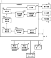
- FIG. 1 is a schematic hardware configuration diagram of a determination device according to an embodiment of the present disclosure.
- FIG. 1 is a schematic configuration diagram of an injection molding machine.
- FIG. 2 is a block diagram schematically showing the functions of the determination device according to the first embodiment. It is a figure which illustrates the molding process which comprises the molding cycle of an injection molding machine. It is a figure which shows the example of the input screen of the tolerance range by 1st Embodiment. It is a graph showing an example of transition of injection pressure. It is a graph showing another example of the transition of injection pressure. It is a graph showing an example of changes in holding pressure. It is a graph showing another example of the transition of injection pressure.
- FIG. 7 is a diagram illustrating an example of an input screen for an allowable range according to the second embodiment.
- FIG. 2 is a block diagram schematically showing the functions of a determination device according to a second embodiment. It is a graph showing an example of changes in injection pressure in a predetermined molding cycle and a reference molding cycle. It is a graph showing another example of the transition of injection pressure in a predetermined molding cycle and a reference molding cycle.
- FIG. 1 is a schematic hardware configuration diagram showing the main parts of a determination device according to an embodiment of the present invention.
- the determination device 1 can be implemented, for example, as a control device that controls the injection molding machine 4 based on a control program.
- the determination device 1 may include, for example, a personal computer attached to a control device that controls the injection molding machine 4, a computer connected to the control device via a wired/wireless network, a fog computer, a cloud server, etc. Can be implemented as a computer.
- an example will be shown in which the determination device 1 is implemented as a computer installed together with a control device.
- the CPU 11 included in the determination device 1 is a processor that controls the determination device 1 as a whole.
- the CPU 11 reads a system program stored in the ROM 12 via the bus 22, and controls the entire determination device 1 according to the system program.
- the RAM 13 temporarily stores temporary calculation data, display data, various data input from the outside, and the like.
- the non-volatile memory 14 is composed of, for example, a memory backed up by a battery (not shown), an SSD (Solid State Drive), etc., and the stored state is maintained even when the power of the determination device 1 is turned off.
- the nonvolatile memory 14 contains programs and data read from external equipment 72 via the interface 15, programs and data input via the input device 71, and data from the injection molding machine 4 and other devices via the network 5.
- the acquired programs, data, etc. are stored.
- the stored data includes, for example, the motor current, voltage, torque, position, speed, acceleration of the drive unit detected by the sensor 8 attached to the injection molding machine 4, the temperature of the injection cylinder, the pressure of the resin, the flow rate, and the flow rate.
- the programs and data stored in the non-volatile memory 14 may be expanded to the RAM 13 at the time of execution/use. Further, various system programs such as a known analysis program are written in the ROM 12 in advance.
- the interface 15 is an interface for connecting the CPU 11 of the determination device 1 to an external device 72 such as a USB device.
- an external device 72 such as a USB device.
- a system program, a program related to the operation of the injection molding machine 4, setting data, etc. are read from the external device 72 side.
- programs, setting data, etc. created and edited within the determination device 1 can be stored in external storage means via the external device 72.
- the interface 20 is an interface for connecting the CPU 11 of the determination device 1 and the wired or wireless network 5.
- the network 5 communicates using technologies such as serial communication such as RS-485, Ethernet (registered trademark) communication, optical communication, wireless LAN, Wi-Fi (registered trademark), and Bluetooth (registered trademark). It's good to be there.
- a control device that controls at least one injection molding machine 4, a fog computer 6, a cloud server 7, and the like are connected to the network 5, and exchange data with the determination device 1.
- the display device 70 outputs and displays each data read into the memory, data obtained as a result of executing a program, etc. via the interface 17. Further, an input device 71 composed of a keyboard, a pointing device, etc. passes commands, data, etc. based on operations by an operator to the CPU 11 via the interface 18.
- FIG. 2 is a schematic configuration diagram of the injection molding machine 4.
- the injection molding machine 4 mainly includes a mold clamping unit 401 and an injection unit 402.
- the mold clamping unit 401 includes a movable platen 416 and a fixed platen 414. Further, a movable mold 412 is attached to the movable platen 416, and a fixed mold 411 is attached to the fixed platen 414, respectively.
- a servo motor 50 is attached to the mold clamping unit 401. By driving the servo motor 50, a ball screw (not shown) is driven via power transmission means such as the belt 420 and the pulley 422, and the movable platen 416 can be moved forward or backward in the direction of the fixed platen 414.
- the injection unit 402 is composed of an injection cylinder 426, a hopper 436 that stores the resin material to be supplied to the injection cylinder 426, and a nozzle 440 provided at the tip of the injection cylinder 426.
- the injection unit 402 can move the injection cylinder 426 forward or backward toward the fixed platen 414 by driving a servo motor (not shown).
- the mold closing unit 401 closes and clamps the mold by moving the movable platen 416, and the injection unit 402 presses the nozzle 440 against the stationary mold 411, and then presses the injection cylinder.
- the resin measured within 426 minutes is injected into the mold.
- sensors 8 are attached to each part of the injection molding machine 4, and various physical quantities necessary for controlling the molding operation are detected.
- detected physical quantities include motor current, voltage, torque, position, speed, acceleration of the drive unit, temperature of the injection cylinder 426, pressure of resin in the injection cylinder 426, flow rate of resin, temperature and pressure of the mold.
- Examples include the temperature and pressure of the mold temperature controller, the position and speed of the molded product take-out machine, and the vibrations and sounds generated in each part of the injection molding machine 4.
- the detected physical quantity is transmitted and output to the determination device 1.
- each detected physical quantity is stored in the RAM 13, nonvolatile memory 14, etc.
- FIG. 3 is a schematic block diagram showing the functions included in the determination device 1 according to the first embodiment of the present disclosure.
- Each function provided in the determination device 1 according to this embodiment is realized by the CPU 11 included in the determination device 1 shown in FIG. 1 executing a system program and controlling the operation of each part of the determination device 1.
- the determination device 1 of this embodiment includes a data acquisition section 110, a feature amount calculation section 120, an allowable range determination section 130, a determination section 140, and an output section 150. Further, in the RAM 13 to nonvolatile memory 14 of the determination device 1, an acquired data storage section 210, which is an area for storing data acquired by the data acquisition section 110 from the servo motor 50, the sensor 8, etc., and a feature amount calculation section 120 are provided. A feature amount storage section 220, which is an area for storing data indicating the calculated feature amount, and an allowable range storage section 230, which is an area for storing an allowable range, are prepared in advance.
- the data acquisition unit 110 collects a plurality of process identification data for identifying molding processes constituting the molding cycle, and data indicating a state related to the operation of the molding cycle. Obtain time series data related to a predetermined physical quantity.
- the process identification data that identifies the molding process is data that identifies which molding process is currently being executed.
- Each molding process that makes up the molding cycle includes a mold closing process, an injection process, a pressure holding process, a measuring process, a decompression process, a cooling process, a mold opening process, an ejection process, an ejection process, etc., as illustrated in FIG. .
- the data indicating the state related to the operation of the molding cycle includes, for example, the motor current, voltage, torque, position, speed, and acceleration obtained from the servo motor 50, the temperature of the injection cylinder 426 detected by the sensor 8, and the inside of the injection cylinder 426.
- the detection value data may include the pressure of the resin, the vibration of the drive unit, the amount of opening/closing of the mold, the pressure inside the mold cavity, the temperature inside the mold cavity, and the like.
- the data acquisition unit 110 may acquire data input by the operator from the input device 71 or data input via the external device 72.
- the data acquisition unit 110 stores the acquired process identification data and data indicating the state of the operation of the molding cycle in the acquired data storage unit 210 in association with each other.
- the feature value calculation unit 120 calculates a predetermined physical quantity acquired in a predetermined molding process among the plurality of molding processes based on the process identification data and time series data related to the predetermined physical quantity stored in the acquired data storage unit 210. Calculate the feature amount of time series data related to.
- the feature quantity of time series data related to a predetermined physical quantity may be a statistical quantity such as a minimum value, a maximum value, etc. of time series data related to a predetermined physical quantity acquired in a predetermined molding process. Further, the feature quantity of time-series data related to a predetermined physical quantity may be one of a plurality of local minimum values and local maximum values.
- the second largest local maximum value among the plurality of local maximum values may be treated as the feature amount of time-series data related to a predetermined physical quantity.
- a statistic related to a value taken by time-series data related to a predetermined physical quantity is referred to as a first feature amount.
- the feature quantities of time-series data related to predetermined physical quantities include the time required from the start of a predetermined molding process until the first feature quantity is detected, the amount of movement of the screw, the amount of rotation of the screw, and the amount of rotation of the movable platen. The amount of movement, the amount of movement of an ejector, the amount of opening/closing of a mold, the amount of rotation of a mold, etc. may be used.
- a value calculated based on the timing at which such a first feature amount is detected is referred to as a second feature amount.
- the feature amount calculation unit 120 stores the calculated first feature amount of the time series data related to the predetermined physical amount in each molding process and the second feature amount calculated based on the first feature amount in the feature amount storage unit 220.
- a feature amount includes a first feature amount and a second feature amount.
- the tolerance determining unit 130 determines the tolerance range for each feature calculated by the feature calculating unit 120 for each predetermined molding process that constitutes the molding cycle.
- the permissible range determining unit 130 determines permissible ranges for each characteristic quantity for each molding process.
- the permissible range determination unit 130 may determine a permissible range that is a combination of a plurality of feature amounts. For example, as illustrated in FIG. 5, the permissible range determining unit 130 displays a screen for inputting a permissible range on the display device 70, and receives input from the input device 71 to determine the value of each feature. An acceptable range may be determined.
- the setting value related to the allowable range may be read from the external device 72, and the allowable range related to the feature amount may be determined based on the read setting value. Furthermore, setting values related to the allowable range are received from other computers such as the fog computer 6 and the cloud server 7 via the network 5, and the allowable range related to the feature amount is determined based on the received setting values. Good too.
- the permissible range determination unit 130 stores the permissible range related to the determined feature amount in the permissible range storage unit 230.
- the determination unit 140 determines the operating state of the injection molding machine 4 based on the feature amount calculated by the feature amount calculation unit 120. For example, the determination unit 140 determines that the operating state of the injection molding machine 4 is normal when the second feature value is within the tolerance range related to the second feature value stored in the tolerance range storage unit 230. It may be determined that the condition is abnormal in other cases. Further, the determination unit 140 determines that the first feature amount is within the tolerance range related to the first feature amount stored in the allowable range storage unit 230, and the second feature amount related to the first feature amount is allowable.
- the operating state of the injection molding machine 4 is determined to be in a normal state, and in other cases, the operating state is determined to be in an abnormal state. It may be determined. In this way, the determination unit 140 may perform determination processing based on at least the second feature amount, or may perform multifaceted determination processing that combines the first feature amount and the second feature amount. You can. The determination unit 140 outputs the determination result of the operating state of the injection molding machine 4 to the output unit 150.
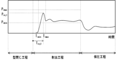
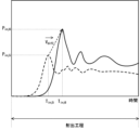
- FIG. 6 is a graph illustrating the transition of the injection pressure detected in the injection process in a predetermined molding cycle.
- the allowable range storage unit 230 stores the allowable range P imin to P imax of the maximum value of the injection pressure in the injection process, which is the first feature quantity, and the allowable range of the time required to detect the maximum value of the injection pressure, which is the second feature quantity. T imin to T imax are stored in advance.
- the feature amount calculation unit 120 calculates the injection pressure maximum value P inj1 as the first feature amount when time series data of the injection pressure in the injection process illustrated in FIG. 6 is acquired.
- the feature amount calculation unit 120 calculates the required time T jnj1 during which the injection pressure maximum value P inj1 , which is the first feature amount, is detected in the injection process as the second feature amount. Then, the feature amount calculation section 120 stores the calculated first feature amount and second feature amount in the feature amount storage section 220.
- the determination unit 140 refers to the second feature stored in the feature storage unit 220 and determines whether the second feature, the required time T jnj1 , falls within the allowable range T imin to T imax . judge. In the example of FIG.
- the determination unit 140 determines that the injection operation in the injection process is normal. At this time, the determination unit 140 refers to the first feature quantity stored in the feature quantity storage unit 220, and further determines whether the first feature quantity, the maximum injection pressure value P inj1 , falls within the allowable range P imin to P imax .
- the injection operation in the injection process may be determined to be normal if both the first feature amount and the second feature amount are within the allowable range.
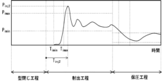
- FIG. 7 is another graph illustrating the transition of the injection pressure detected in the injection process in a predetermined molding cycle.
- the feature amount calculation unit 120 calculates the injection pressure maximum value P inj2 as a first feature amount when the time series data of the injection pressure in the injection process illustrated in FIG. 7 is acquired. Next, the feature amount calculation unit 120 calculates the required time T jnj2 during which the injection pressure maximum value P inj2 , which is the first feature amount, is detected in the injection process as a second feature amount. Then, the feature amount calculation unit 120 stores the calculated first feature amount and second feature amount in the feature amount storage unit 220.
- the determination unit 140 refers to the second feature stored in the feature storage unit 220 and determines whether the second feature, which is the required time T jnj2 , falls within the allowable range T imin to T imax . judge. In the example of FIG. 7, since the required time T jnj2 , which is the second characteristic amount, is outside the allowable range T imin to T imax , the determining unit 140 determines that the injection operation in the injection process is abnormal. The determination unit 140 may determine more precisely whether both the first feature amount and the second feature amount are within an allowable range. In the example of FIG. 7, since both the first feature amount and the second feature amount are outside the allowable range, the determination unit 140 determines that the injection operation in the injection process is abnormal.
- FIG. 8 is a graph illustrating the transition of the holding pressure detected in the holding pressure step in a predetermined molding cycle.
- the allowable range storage unit 230 stores the first feature quantity, which is the allowable range P pmin to P pmax of the minimum value of the packing pressure in the pressure holding process, and the second feature quantity, which is the time required to detect the minimum value of the packing pressure.
- the allowable range T pmin to T pmax is stored in advance.
- the feature amount calculation unit 120 calculates the minimum packing pressure value P pack1 as the first feature amount.
- the feature quantity calculation unit 120 calculates the required time T pack1 during which the first feature quantity, the minimum packing pressure value P pack1 , was detected in the pressure packing process as a second feature quantity. Then, the feature amount calculation section 120 stores the calculated first feature amount and second feature amount in the feature amount storage section 220.
- the determining unit 140 refers to the second feature quantity stored in the feature quantity storage unit 220 and determines whether the required time T pack1 , which is the second feature quantity, falls within the allowable range T pmin to T pmax . judge. In the example of FIG. 8, since the required time T pack1 , which is the second characteristic amount, is outside the allowable range T pmin to T pmax , the determining unit 140 determines that the injection operation in the injection process is abnormal.
- the first characteristic amount the minimum value of the packing pressure P pack1 , falls within the allowable range P pmin to P pmax . If the determination is made using only the first feature amount, abnormalities such as those illustrated in FIG. 8 will be overlooked, but by making the determination using the second feature amount, the state can be determined more reliably and with improved accuracy. You will be able to do this.
- the output unit 150 displays and outputs the determination result of the state of the injection molding machine 4 input from the determination unit 140 to the display device 70.
- the output unit 150 may transmit and output the determination result to the injection molding machine 4 via the network 5.
- the output may be transmitted to a higher-level computer such as the fog computer 6 or the cloud server 7.
- the data may be output to a log recording area provided in advance on the nonvolatile memory 14 or the like.
- the output unit 150 may output a signal to limit the operation of the injection molding machine 4, for example, when the determination result indicates an abnormal operation of the injection molding machine 4.
- This limiting signal may be, for example, a signal that stops or decelerates the operation of the injection molding machine, or limits the drive torque of the prime mover that drives the injection molding machine.
- the determination device 1 calculates a first feature amount based on time series data acquired in a predetermined molding process of the injection molding machine 4, and further calculates a first feature amount from the calculated first feature amount. 2. Calculate the feature amount. Then, a determination is made using these calculated feature amounts as an index.
- Factors that affect the quality of molded products produced by the injection molding machine 4 include, for example, differences in the state of the resin measured in the measuring process (e.g., capacity, density, viscosity, temperature), and Examples include differences in the degree of wear and deterioration of drive parts.
- the amount of resin filled into the cavity of the mold varies from molding cycle to molding cycle, resulting in variations in the mass of the molded product and molding defects (for example, short circuits, warping, etc.).
- molding defects for example, short circuits, warping, etc.
- the quality of the molded product may vary, or foreign matter may get mixed into the molding material, resulting in molding defects.
- the mixing ratio of the mixed material it will affect the quality of the molded product.
- the determination device 1 calculates a first feature amount indicating the characteristics of time-series data, and further calculates "from the start of the molding process until the first feature amount is reached" based on the first feature amount.
- the operating state of the injection molding machine 4 is determined using the second feature amount (for example, the required time) indicating the timing of the injection molding machine 4.
- the determination device 1 By making a judgment using this as an index, a more reliable judgment can be realized. Further, by using the two indicators of the first feature amount and the second feature amount together, it is possible to perform a two-dimensional determination, and it is possible to improve the accuracy of determining the operating state of the injection molding machine 4.
- the first feature quantity is pressure
- the second feature quantity is time required/screw movement amount, etc.
- the determination device 1 according to the second embodiment will be described below.
- the determination device 1 according to the present embodiment differs from the determination device 1 according to the first embodiment in that, in the determination process in the determination unit 140, the first feature amount and the second feature amount are treated as a combined vector.
- the determination unit 140 uses a vector whose elements are the first feature calculated by the feature calculation unit 120 and the second feature calculated from the first feature, respectively. Determine the operating state of machine 4. For example, the determination unit 140 calculates a vector with the second feature amount as the first element and the first feature amount as the second element, and calculates the norm (size, length) of the calculated vector and the direction (angle) of the vector. It is determined whether or not it falls within a predetermined tolerance range. Then, if both are within the allowable range, it may be determined that the operating state of the injection molding machine 4 is in a normal state, and in other cases, it may be determined that the operating state is in an abnormal state. Furthermore, if at least either the norm (size, length) of the vector or the direction (angle) of the vector is within the allowable range, it is determined that the operating state of the injection molding machine 4 is normal. You can.
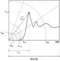
- FIG. 9 is a graph illustrating the transition of the injection pressure detected in the injection process in a predetermined molding cycle.
- the tolerance storage unit 230 stores in advance a tolerance range A imin to A imax of the norm of the vector related to the maximum injection pressure value, and a tolerance range B imin to B imax of the direction of the vector related to the maximum injection pressure value. .
- the feature amount calculation unit 120 calculates the injection pressure maximum value P inj3 as the first feature amount when time series data of the injection pressure in the injection process illustrated in FIG. 9 is acquired. Next, the feature amount calculation unit 120 calculates the required time T jnj3 during which the injection pressure maximum value P inj3 , which is the first feature amount, is detected in the injection process as a second feature amount.
- the feature amount calculation section 120 stores the calculated first feature amount and second feature amount in the feature amount storage section 220.
- the determining unit 140 refers to the first feature amount and the second feature amount stored in the feature amount storage unit 220, and calculates a vector V inj3 having the first feature amount and the second feature amount as elements.
- the determination unit 140 determines whether
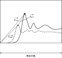
- FIG. 10 is an example of a tolerance range input screen displayed by the tolerance range determination unit 130 according to the present embodiment. As illustrated in FIG. 10, the waveform graph of predetermined time series data, the tolerance range of the norm of the input vector, and the tolerance range of the direction of the vector are superimposed on the tolerance input screen. Good too. By displaying in this manner, the user who inputs the tolerance range can visually check the graph on the operation screen and easily determine the value of each tolerance range.
- the determination device 1 according to the present embodiment is the determination device according to the first and second embodiments in that, in the determination process in the determination unit 140, determination is made based on predetermined first feature amounts and second feature amounts. Different from 1.
- FIG. 11 is a schematic block diagram showing the functions included in the determination device 1 according to the third embodiment of the present disclosure.
- Each function provided in the determination device 1 according to this embodiment is realized by the CPU 11 included in the determination device 1 shown in FIG. 1 executing a system program and controlling the operation of each part of the determination device 1.
- the determination device 1 of the present embodiment further includes a reference feature amount determination section 160 in addition to the data acquisition section 110, the feature amount calculation section 120, the allowable range determination section 130, the determination section 140, and the output section 150.
- a reference feature amount determination section 160 in addition to the data acquisition section 110, the feature amount calculation section 120, the allowable range determination section 130, the determination section 140, and the output section 150.
- the RAM 13 to nonvolatile memory 14 of the determination device 1 are areas for storing feature amounts that serve as a reference.
- a reference feature storage unit 240 is prepared in advance.
- the functions of the data acquisition section 110 and the feature amount calculation section 120 according to this embodiment are the same as those of the data acquisition section 110 and the feature amount calculation section 120 according to the first and second embodiments.
- the reference feature quantity determination unit 160 determines reference values related to feature quantities used when determining the state of the injection molding machine 4.
- the reference feature determining unit 160 determines reference values for the first feature and the second feature for each molding process.
- the reference feature determination unit 160 displays, for example, on the display device 70 a screen for determining reference values for the first feature amount and the second feature amount, and receives input from the input device 71 to determine the reference value. may be determined.
- reference values related to the first feature amount and the second feature amount obtained in a molding cycle in which a good molded product was molded may be directly input.
- time-series data related to a plurality of predetermined physical quantities acquired when the injection operation is normally performed may be displayed on the screen in a selectable manner, and the time-series data may be selected from there.
- the reference feature amount determination unit 160 can determine the first feature amount and the second feature amount calculated based on the selected time series data as the reference value.
- the reference feature determining unit 160 may read out the reference value from the external device 72 and determine the read reference value.
- the reference value may be received from another computer such as the fog computer 6 or the cloud server 7 via the network 5, and the received value may be determined as the reference value.
- the reference value may be determined by determining reference values associated with each of the first feature amount and the second feature amount as the first reference value and the second reference value. Further, similarly to the second embodiment, the reference value may be determined as a vector having the first feature amount and the second feature amount as elements.
- the reference feature determination unit 160 stores the determined reference value in the reference feature storage unit 240.
- the permissible range determination unit 130 determines the permissible range for each feature amount based on the reference values for the first feature amount and the second feature amount determined by the reference feature amount determination unit 160. .
- the allowable range determining unit 130 determines the allowable range regarding the feature amount as the amount of difference from the reference value.
- the difference between the first feature amount and the first reference value, the second feature amount and the second reference value may be determined as the difference between Furthermore, if the first feature amount and the second feature amount are treated as vectors each having elements as exemplified in the second embodiment, the element composed of the first reference value and the second reference value as a reference is A vector having a starting point and an element constituted by the first feature amount and the second feature amount as an end point may be used as a difference vector, and the tolerance range may be determined as the norm and direction of this difference vector.
- the determination unit 140 converts the first feature amount calculated by the feature amount calculation unit 120 and the second feature amount calculated from the first feature amount into the first feature amount stored in the reference feature amount storage unit 240.
- a difference amount between the feature amount and the reference value is calculated by comparing the first reference value and the second reference value. Then, when each calculated difference falls within the tolerance range related to any of the feature quantities stored in the tolerance range storage unit 230 in view of the reference value related to the feature quantity, the injection molding machine 4 is operated. It is determined that the state is normal.
- FIG. 12 is a graph illustrating changes in injection pressure detected in the injection process in a predetermined molding cycle and a reference molding cycle.
- the solid line graph shows time-series data of the injection pressure detected in the injection process in a predetermined molding cycle to be determined.
- the broken line graph shows time-series data of the injection pressure of the molding cycle that is the reference selected for determining the reference value.
- the reference feature quantity determination unit 160 reads the first feature quantity and the second feature quantity related to the time series data of the injection pressure of the molding cycle serving as the reference from the feature quantity storage unit 220, and determines the reference value of the feature quantity related to the injection pressure.
- a vector having the first feature amount and the second feature amount as elements is calculated as a reference vector V injB , and the calculated reference vector V injB is stored in the reference feature amount storage unit 240.
- the tolerance storage unit 230 stores the tolerance range E min to E max of the norm difference from the vector related to the maximum value of the injection pressure based on the reference vector V injB , and the maximum injection pressure value based on the reference vector V injB .
- a permissible range F min to F max of the direction difference seen from the vector related to the value is stored in advance.
- the feature amount calculation unit 120 calculates a first feature amount and a second feature amount when the time series data of injection pressure in the injection process illustrated in FIG.
- FIG. 13 is another graph illustrating the transition of the injection pressure detected in the injection process in a predetermined molding cycle and a reference molding cycle.
- the injection molding machine 4 Determine the operating status of the
- the solid line graph shows time-series data of injection pressure detected in the injection process in a predetermined molding cycle to be determined.
- the feature quantity calculation unit 120 calculates the injection pressure maximum value P inj6 as the first feature quantity of a predetermined molding cycle, and the required time T jnj6 as the second feature quantity, and stores them in the feature quantity memory. 220.
- the broken line graph shows time-series data of the injection pressure selected as the reference molding cycle.
- the reference feature determining unit 160 determines the injection pressure maximum value P inj5 as the first reference value of the reference molding cycle and the required time T jnj5 as the second reference value, and determines the reference feature.
- the amount is stored in the amount storage section 240.
- the determining unit 140 starts from the elements of the first reference value P inj5 and the second reference value T jnj5 called from the reference feature storage unit 240, and determines the first feature P inj6 and the second reference value called from the feature storage unit 220.
- a vector whose end point is the element of the feature amount T jnj6 is calculated as a difference vector V dif2 .
- the tolerance storage unit 230 stores in advance a tolerance range E min to E max related to the norm of the difference vector V dif2 and a tolerance range F min to F max related to the direction of the difference vector V dif2 .
- the determination unit 140 determines whether
- the determination unit 140 determines that, for example,
- the determination unit 140 outputs the determination result of the operating state of the injection molding machine 4 to the output unit 150.
- the output unit 150 may output a signal to limit the operation of the injection molding machine 4, for example, when the determination result indicates an abnormal operation of the injection molding machine 4.
- the determination device 1 can determine the operating state of the injection molding machine 4 based on a predetermined feature set by the user. For a while after the injection molding machine 4 starts operating, the temperature of the mold increases as the molding cycle in which the mold is filled with molten resin in the injection cylinder to produce a molded product is repeated. Therefore, the first/second characteristic quantities (for example, the maximum temperature value and the maximum injection pressure value of the injection cylinder in the injection process) vary while repeating the molding cycle. Furthermore, when resin lots are changed during production, or when operating command values related to injection, metering, etc. are changed, the characteristic amounts will fluctuate for a while after the change in these conditions.
- the first/second characteristic quantities for example, the maximum temperature value and the maximum injection pressure value of the injection cylinder in the injection process
- the determination device 1 is implemented as a computer installed alongside a control device. However, it may be implemented as a control device that controls the injection molding machine 4, for example. Further, it can be implemented as a host computer such as a fog computer 6 or a cloud server 7 connected to the control device of the injection molding machine 4 via a wired/wireless network. Further, when a plurality of injection molding machines 4 are connected to each other via a network, the determination device 1 acquires process identification data and time series data from the plurality of injection molding machines 4, and The operating state of the injection molding machine 4 may also be determined.
- Judgment device 4 Injection molding machine 5
- Network 6 Fog computer 7
- Cloud server 8 Sensor 11
- CPU 12 ROM 13 RAM 14
- Bus 70 Display device 71
- Input device 72 External device 110
- Data acquisition unit 120 Feature calculation unit 130
- Tolerance range determination unit 140 Judgment unit 150
- Reference feature determination unit 210 Acquired data storage unit 220
- Feature storage unit 230
- Tolerance range storage unit 240 Reference feature storage unit
Landscapes
- Engineering & Computer Science (AREA)
- Manufacturing & Machinery (AREA)
- Mechanical Engineering (AREA)
- Injection Moulding Of Plastics Or The Like (AREA)
Abstract
本開示による判定装置は、成形サイクルを構成する複数の成形工程を識別する工程識別データ及び射出成形機に係る状態を示すデータとしての所定の物理量に係る時系列データを取得するデータ取得部と、工程識別データ及び時系列データに基づいて、複数の成形工程の内の所定の成形工程おいて取得された時系列データを統計処理することで第1特徴量と、所定の成形工程を開始してから第1特徴量が検出されたタイミングを示す第2特徴量とを算出する特徴量算出部と、少なくとも第2特徴量に基づいて、射出成形機の運転状態を判定する判定部と、判定結果を出力する出力部と、を備える。
Description
本開示は、判定装置及び判定方法に関する。
成形時に観測されるデータ(例えば、時系列のデータ、代表値)を監視して、成形品または射出成形機の運転状態の良否を判定することが行われている。例えば、射出成形機の運転状態を示す「時系列のデータ(例えば、圧力、トルクなど)」を成形サイクル毎に観測して、良品時の成形サイクルで観測した時系列のデータと比較することによって、成形品または射出成形機の運転状態の良否を判定すること、は公知である。
1つの成形品を生産する成形サイクルは、複数の成形工程(例えば、射出工程、計量工程など)から構成されている。時系列のデータより、各成形工程における「代表値(例えば、射出工程における圧力の最大値など)」を算出し、算出された代表値と予め定めた許容範囲とを比較して、成形品または射出成形機の運転状態の良否を判定すること、も公知である。
特許文献1には、成形サイクル毎に各種モニタリング項目を収集し、オペレータが指定したモニタリング項目を画面上に表示すること、が示されている。また、特許文献2には、監視項目とする成形データに上限値や下限値を設けて良否判別を行なうこと、警報を報知したり、射出成形機の運転を停止したりすること、が示されている。更に、特許文献3には、経時変化データ(時系列のデータ)と基準タイミングとを関連づけて記憶させておき、成形サイクルを終えた後に、記憶しておいた経時変化データと基準タイミングの内より所望の抽出タイミングに合致する検出値を抽出すること、が示されている。
射出成形機の運転状態の判定に特徴量を用いることは公知である。この特徴量がばらつく態様として、以下に示す2つの態様がある。
1)特徴量(以下、「第1特徴量」と称する)の値が変動すること、例えば、射出工程における射出圧力最大値の値が変動することなどが挙げられる。
2)所定の成形工程において所定の第1特徴量が検出されるタイミング(例えば、該成形工程が開始されてからの所要時間、可動部の移動量など。以下、「第2特徴量」と称する)が変動すること、例えば、射出工程が開始されてから射出圧力最大値に達するまでの所要時間が変動することなどが挙げられる。
1)特徴量(以下、「第1特徴量」と称する)の値が変動すること、例えば、射出工程における射出圧力最大値の値が変動することなどが挙げられる。
2)所定の成形工程において所定の第1特徴量が検出されるタイミング(例えば、該成形工程が開始されてからの所要時間、可動部の移動量など。以下、「第2特徴量」と称する)が変動すること、例えば、射出工程が開始されてから射出圧力最大値に達するまでの所要時間が変動することなどが挙げられる。
第1特徴量の値が許容範囲外に変動する場合、良好な成形品は得られない。また、第1特徴量の値が許容範囲内に収まっている場合であっても、第2特徴量の値が変動すると、良好な成形品を得られないことがある。従来は、第1特徴量を検出したタイミング(第2特徴量)が許容範囲から外れた場合でも、射出成形機の動作状態が正常であると誤判定するという問題が有った。
そのため、少なくとも第1特徴量を検出したタイミングを考慮して、射出成形機の運転状態の異常有無の判定精度を向上すること、が望まれている。
そのため、少なくとも第1特徴量を検出したタイミングを考慮して、射出成形機の運転状態の異常有無の判定精度を向上すること、が望まれている。
本開示による射出成形機の判定装置は、成形サイクルを構成する複数の成形工程毎に、所定の時系列データを統計処理した第1特徴量を算出する。続いて、所定の成形工程を開始してから第1特徴量が検出されたタイミングを示す第2特徴量を算出し、算出された特徴量を用いて射出成形機の運転状態を判定することで、上記課題を解決する。
そして、本開示の一態様は、成形品を製造する成形サイクルを繰り返し行う射出成形機の運転状態を判定する判定装置であって、前記成形サイクルを構成する複数の成形工程を識別する工程識別データ及び前記射出成形機に係る状態を示すデータとしての所定の物理量に係る時系列データを取得するデータ取得部と、前記工程識別データ及び前記時系列データに基づいて、前記複数の成形工程の内の所定の成形工程おいて取得された前記時系列データを統計処理することで第1特徴量と、前記所定の成形工程を開始してから前記第1特徴量が検出されたタイミングを示す第2特徴量とを算出する特徴量算出部と、少なくとも前記第2特徴量に基づいて、前記射出成形機の運転状態を判定する判定部と、前記判定部による判定結果を出力する出力部と、を備えた判定装置である。
本開示の他の態様は、成形品を製造する成形サイクルを繰り返し行う射出成形機の運転状態を判定する判定装置が実行する判定方法であって、前記判定装置が、前記成形サイクルを構成する複数の成形工程を識別する工程識別データ及び前記射出成形機に係る状態を示すデータとしての所定の物理量に係る時系列データを取得するステップと、前記工程識別データ及び前記時系列データに基づいて、前記複数の成形工程の内の所定の成形工程おいて取得された前記時系列データを統計処理することで第1特徴量と、前記所定の成形工程を開始してから前記第1特徴量が検出されたタイミングを示す第2特徴量とを算出するステップと、少なくとも前記第2特徴量に基づいて、前記射出成形機の運転状態を判定するステップと、前記判定するステップによる判定結果を出力するステップと、を実行する判定方法である。
本開示の一態様により、第1特徴量から第2特徴量を算出し、算出した特徴量を指標として判定を実現することで、より確実な射出成形機の運転状態の判定を実現できることが見込まれる。
以下、本発明の実施形態を図面と共に説明する。
図1は本発明の一実施形態による判定装置の要部を示す概略的なハードウェア構成図である。本実施形態による判定装置1は、例えば制御用プログラムに基づいて射出成形機4を制御する制御装置として実装することができる。また、判定装置1は、例えば射出成形機4を制御する制御装置と併設されたパソコンや、該制御装置と有線/無線のネットワークを介して接続されたコンピュータ、フォグコンピュータ、クラウドサーバなどの他のコンピュータとして実装することができる。本実施形態では、判定装置1を制御装置と併設されたコンピュータとして実装した例を示す。
図1は本発明の一実施形態による判定装置の要部を示す概略的なハードウェア構成図である。本実施形態による判定装置1は、例えば制御用プログラムに基づいて射出成形機4を制御する制御装置として実装することができる。また、判定装置1は、例えば射出成形機4を制御する制御装置と併設されたパソコンや、該制御装置と有線/無線のネットワークを介して接続されたコンピュータ、フォグコンピュータ、クラウドサーバなどの他のコンピュータとして実装することができる。本実施形態では、判定装置1を制御装置と併設されたコンピュータとして実装した例を示す。
本実施形態による判定装置1が備えるCPU11は、判定装置1を全体的に制御するプロセッサである。CPU11は、バス22を介してROM12に格納されたシステム・プログラムを読み出し、該システム・プログラムに従って判定装置1全体を制御する。RAM13には一時的な計算データや表示データ、及び外部から入力された各種データ等が一時的に格納される。
不揮発性メモリ14は、例えば図示しないバッテリでバックアップされたメモリやSSD(Solid State Drive)等で構成され、判定装置1の電源がオフされても記憶状態が保持される。不揮発性メモリ14には、インタフェース15を介して外部機器72から読み込まれたプログラムやデータ、入力装置71を介して入力されたプログラムやデータ、ネットワーク5を介して射出成形機4や他の装置から取得されたプログラムやデータ等が記憶される。記憶されるデータには、例えば射出成形機4に取り付けられたセンサ8により検出された駆動部のモータ電流、電圧、トルク、位置、速度、加速度、射出シリンダの温度、樹脂の圧力、流量、流速、金型の温度や圧力、金型温調機の温度や圧力、成形品取り出し機の位置や速度、射出成形機4の各部に発生する振動や音等の物理量に係るデータが含まれていてよい。不揮発性メモリ14に記憶されたプログラムやデータは、実行時/利用時にはRAM13に展開されてもよい。また、ROM12には、公知の解析プログラムなどの各種システム・プログラムがあらかじめ書き込まれている。
インタフェース15は、判定装置1のCPU11とUSB装置等の外部機器72と接続するためのインタフェースである。外部機器72側からは、例えばシステム・プログラムや射出成形機4の運転に係るプログラム、設定データ等が読み込まれる。また、判定装置1内で作成・編集したプログラムや設定データ等は、外部機器72を介して外部記憶手段に記憶させることができる。
インタフェース20は、判定装置1のCPU11と有線乃至無線のネットワーク5とを接続するためのインタフェースである。ネットワーク5は、例えばRS-485等のシリアル通信、Ethernet(登録商標)通信、光通信、無線LAN、Wi-Fi(登録商標)、Bluetooth(登録商標)等の技術を用いて通信をするものであってよい。ネットワーク5には、少なくとも1つの射出成形機4を制御する制御装置やフォグコンピュータ6、クラウドサーバ7等が接続され、判定装置1との間で相互にデータのやり取りを行っている。
表示装置70には、メモリ上に読み込まれた各データ、プログラム等が実行された結果として得られたデータ等がインタフェース17を介して出力されて表示される。また、キーボードやポインティングデバイス等から構成される入力装置71は、オペレータによる操作に基づく指令、データ等をインタフェース18を介してCPU11に渡す。
図2は、射出成形機4の概略構成図である。射出成形機4は、主として型締ユニット401と射出ユニット402とから構成されている。型締ユニット401には、可動プラテン416と固定プラテン414が備えられている。また、それぞれ可動プラテン416には可動側金型412が、固定プラテン414には固定側金型411が取り付けられている。型締ユニット401にはサーボモータ50が取り付けられている。そして、サーボモータ50を駆動させることで、ベルト420、プーリ422などの動力伝達手段を介して図示しないボールねじが駆動され、可動プラテン416を固定プラテン414方向に前進又は後退させることができる。
一方、射出ユニット402は、射出シリンダ426と、射出シリンダ426に供給する樹脂材料を溜めるホッパ436と、射出シリンダ426の先端に設けられたノズル440とから構成されている。射出ユニット402は、図示しないサーボモータを駆動させることで、射出シリンダ426を固定プラテン414方向に前進又は後退させることができる。
1つの成形品を製造する成形サイクルでは、型締ユニット401で、可動プラテン416の移動によって型閉じ・型締めを行い、射出ユニット402で、ノズル440を固定側金型411に押し付けてから射出シリンダ426の内に計量された樹脂を金型内に射出する。これらの動作は図示しない判定装置1からの指令により制御される。
また、射出成形機4の各部には図示しないセンサ8が取り付けられており、成形動作の制御に必要な各種物理量が検出される。検出される物理量の例としては、駆動部のモータ電流、電圧、トルク、位置、速度、加速度、射出シリンダ426の温度、射出シリンダ426内の樹脂の圧力、樹脂の流量、金型の温度や圧力、金型温調機の温度や圧力、成形品取り出し機の位置や速度、射出成形機4の各部に発生する振動や音などが例示される。検出された物理量は判定装置1に送信出力される。判定装置1では、検出された各物理量がRAM13や不揮発性メモリ14などに記憶される。
図3は、本開示の第1実施形態による判定装置1が備える機能を概略的なブロック図として示したものである。本実施形態による判定装置1が備える各機能は、図1に示した判定装置1が備えるCPU11がシステム・プログラムを実行し、判定装置1の各部の動作を制御することにより実現される。
本実施形態の判定装置1は、データ取得部110、特徴量算出部120、許容範囲決定部130、判定部140、出力部150を備える。また、判定装置1のRAM13乃至不揮発性メモリ14には、データ取得部110がサーボモータ50やセンサ8等から取得したデータを記憶するための領域である取得データ記憶部210、特徴量算出部120が算出した特徴量を示すデータを記憶するための領域である特徴量記憶部220、許容範囲を記憶するための領域である許容範囲記憶部230が予め用意されている。
データ取得部110は、射出成形機4が成形サイクルの動作を行う際に、該成形サイクルを構成する成形工程を識別する複数の工程識別データと、該成形サイクルの動作に係る状態を示すデータとして所定の物理量に係る時系列データを取得する。成形工程を識別する工程識別データは、現在実行されている成形工程がいずれの成形工程であるのかを識別するデータである。成形サイクルを構成する各成形工程は、図4に例示するように、型閉じ工程、射出工程、保圧工程、計量工程、減圧工程、冷却工程、型開き工程、突き出し工程、取り出し工程などを含む。成形サイクルの動作に係る状態を示すデータには、例えばサーボモータ50から取得されるモータ電流、電圧、トルク、位置、速度、加速度や、センサ8が検出した射出シリンダ426の温度、射出シリンダ426内の樹脂の圧力、駆動部の振動、金型の開閉量、金型のキャビティ内の圧力、金型のキャビティ内の温度などの検出値データを含んでいてよい。なお、データ取得部110は、オペレータが入力装置71から入力したデータや、外部機器72を介して入力されたデータを取得するようにしてもよい。データ取得部110は、取得した工程識別データ及び成形サイクルの動作に係る状態を示すデータを関連付けて取得データ記憶部210に記憶する。
特徴量算出部120は、取得データ記憶部210に記憶された工程識別データ及び所定の物理量に係る時系列データに基づいて、複数の成形工程の内の所定の成形工程において取得された所定の物理量に係る時系列データの特徴量を算出する。所定の物理量に係る時系列データの特徴量は、所定の成形工程において取得された所定の物理量に係る時系列データの最小値、最大値などの統計量であってよい。また、所定の物理量に係る時系列データの特徴量は、複数の極小値、極大値の内のいずれかの極小値、極大値であってもよい。例えば、複数の極大値の内で2番目に大きな極大値を所定の物理量に係る時系列データの特徴量として扱うようにしてよい。このような所定の物理量に係る時系列データが取る値に係る統計量を、本明細書では第1特徴量と称している。また、所定の物理量に係る時系列データの特徴量は、所定の成形工程を開始してから第1特徴量が検出されるまでの所要時間、スクリュの移動量、スクリュの回転量、可動プラテンの移動量、エジェクタの移動量、金型の開閉量、金型の回転量などであってもよい。このような第1特徴量が検出されるタイミングに基づいて算出される値を、本明細書では第2特徴量と称している。特徴量算出部120は、算出したそれぞれの成形工程における所定の物理量に係る時系列データの第1特徴量と、第1特徴量に基づいて算出される第2特徴量を特徴量記憶部220に記憶する。以下の説明では、単に特徴量と記した場合は、第1特徴量と第2特徴量を含む。
許容範囲決定部130は、成形サイクルを構成する所定の成形工程毎に特徴量算出部120が算出するそれぞれの特徴量に係る許容範囲を決定する。許容範囲決定部130は、成形工程毎に、それぞれの特徴量に係る許容範囲を決定する。許容範囲決定部130は、複数の特徴量を組み合わせた許容範囲を決定するようにしてもよい。許容範囲決定部130は、例えば図5に例示するように、表示装置70に対して許容範囲を入力するための画面を表示し、入力装置71からの入力を受け付けることでそれぞれの特徴量に係る許容範囲を決定するようにしてよい。また、外部機器72から許容範囲に係る設定値を読み出し、読み出した設定値に基づいて特徴量に係る許容範囲を決定するようにしてもよい。更に、ネットワーク5を介して、フォグコンピュータ6やクラウドサーバ7などの他のコンピュータから許容範囲に係る設定値を受信し、受信した設定値に基づいて特徴量に係る許容範囲を決定するようにしてもよい。許容範囲決定部130は、決定した特徴量に係る許容範囲を許容範囲記憶部230に記憶する。
判定部140は、特徴量算出部120が算出する特徴量に基づいて、射出成形機4の運転状態を判定する。判定部140は、例えば第2特徴量が許容範囲記憶部230に記憶されている第2特徴量に係る許容範囲内に収まっている場合に、射出成形機4の運転状態が正常な状態にあると判定し、その他の場合に異常な状態であると判定するようにしてもよい。また、判定部140は、例えば第1特徴量が許容範囲記憶部230に記憶されている第1特徴量に係る許容範囲内にあり、かつ、該第1特徴量に係る第2特徴量が許容範囲記憶部230に記憶されている第2特徴量に係る許容範囲内にある場合に、射出成形機4の運転状態は正常な状態にあると判定し、その他の場合に異常な状態であると判定するようにしてもよい。このように、判定部140は、少なくとも第2特徴量に基づいた判定処理を行うようにしてよいし、また、第1特徴量及び第2特徴量を組み合わせた多角的な判定処理を行うようにしてもよい。判定部140は、射出成形機4の運転状態の判定結果を出力部150へと出力する。
図6~8を用いて、判定部140による判定処理について説明する。
図6は、所定の成形サイクルにおける射出工程にて検出された射出圧力の推移を例示するグラフである。許容範囲記憶部230には、第1特徴量である射出工程における射出圧力の最大値の許容範囲Pimin~Pimaxと、第2特徴量である射出圧力最大値を検出した所要時間の許容範囲Timin~Timaxが予め記憶されている。特徴量算出部120は、図6に例示される射出工程における射出圧力の時系列データが取得された時、第1特徴量として射出圧力最大値Pinj1を算出する。次に、特徴量算出部120は、射出工程において第1特徴量である射出圧力最大値Pinj1が検出された所要時間Tjnj1を第2特徴量として算出する。そして、特徴量算出部120は、算出した第1特徴量と第2特徴量とを特徴量記憶部220に記憶する。判定部140は、特徴量記憶部220に記憶された第2特徴量を参照して、第2特徴量である所要時間Tjnj1が、許容範囲Timin~Timax内に収まっているか否かを判定する。図6の例では、第2特徴量である所要時間Tjnj1が、許容範囲Timin~Timax内に収まっているので、判定部140は、射出工程における射出動作が正常であると判定する。この時、判定部140は、特徴量記憶部220に記憶された第1特徴量を参照して、更に第1特徴量である射出圧力最大値Pinj1が許容範囲Pimin~Pimax内に収まっているか否かを判定し、第1特徴量及び第2特徴量の双方が共に許容範囲内に収まっている場合に、射出工程における射出動作が正常であると判定するようにしてもよい。
図6は、所定の成形サイクルにおける射出工程にて検出された射出圧力の推移を例示するグラフである。許容範囲記憶部230には、第1特徴量である射出工程における射出圧力の最大値の許容範囲Pimin~Pimaxと、第2特徴量である射出圧力最大値を検出した所要時間の許容範囲Timin~Timaxが予め記憶されている。特徴量算出部120は、図6に例示される射出工程における射出圧力の時系列データが取得された時、第1特徴量として射出圧力最大値Pinj1を算出する。次に、特徴量算出部120は、射出工程において第1特徴量である射出圧力最大値Pinj1が検出された所要時間Tjnj1を第2特徴量として算出する。そして、特徴量算出部120は、算出した第1特徴量と第2特徴量とを特徴量記憶部220に記憶する。判定部140は、特徴量記憶部220に記憶された第2特徴量を参照して、第2特徴量である所要時間Tjnj1が、許容範囲Timin~Timax内に収まっているか否かを判定する。図6の例では、第2特徴量である所要時間Tjnj1が、許容範囲Timin~Timax内に収まっているので、判定部140は、射出工程における射出動作が正常であると判定する。この時、判定部140は、特徴量記憶部220に記憶された第1特徴量を参照して、更に第1特徴量である射出圧力最大値Pinj1が許容範囲Pimin~Pimax内に収まっているか否かを判定し、第1特徴量及び第2特徴量の双方が共に許容範囲内に収まっている場合に、射出工程における射出動作が正常であると判定するようにしてもよい。
図7は、所定の成形サイクルにおける射出工程で検出された射出圧力の推移を例示する他のグラフである。特徴量算出部120は、図7に例示される射出工程における射出圧力の時系列データが取得された時、第1特徴量として射出圧力最大値Pinj2を算出する。次に、特徴量算出部120は、射出工程において第1特徴量である射出圧力最大値Pinj2が検出された所要時間Tjnj2を第2特徴量として算出する。そして、特徴量算出部120は、算出した第1特徴量と第2特徴量とを特徴量記憶部220に記憶する。判定部140は、特徴量記憶部220に記憶された第2特徴量を参照して、第2特徴量である所要時間Tjnj2が、許容範囲Timin~Timax内に収まっているか否かを判定する。図7の例では、第2特徴量である所要時間Tjnj2が、許容範囲Timin~Timaxから外れているので、判定部140は、射出工程における射出動作が異常であると判定する。判定部140は、より厳密に第1特徴量及び第2特徴量の双方が共に許容範囲内に収まっているか否かを判定するようにしてもよい。図7の例では、第1特徴量及び第2特徴量のいずれも許容範囲から外れているので、判定部140は、やはり射出工程における射出動作が異常であると判定する。
図8は、所定の成形サイクルにおける保圧工程で検出された保圧圧力の推移を例示するグラフである。許容範囲記憶部230には、第1特徴量である保圧工程における保圧圧力の最小値の許容範囲Ppmin~Ppmaxと、第2特徴量である保圧圧力最小値を検出した所要時間の許容範囲Tpmin~Tpmaxが予め記憶されている。特徴量算出部120は、図8に例示される保圧工程における保圧圧力の時系列データが取得された時、第1特徴量として保圧圧力最小値Ppack1を算出する。次に、特徴量算出部120は、保圧工程において第1特徴量である保圧圧力最小値Ppack1が検出された所要時間Tpack1を第2特徴量として算出する。そして、特徴量算出部120は、算出した第1特徴量と第2特徴量とを特徴量記憶部220に記憶する。判定部140は、特徴量記憶部220に記憶された第2特徴量を参照して、第2特徴量である所要時間Tpack1が、許容範囲Tpmin~Tpmax内に収まっているか否かを判定する。図8の例では、第2特徴量である所要時間Tpack1が、許容範囲Tpmin~Tpmaxから外れているので、判定部140は、射出工程における射出動作が異常であると判定する。図8の例では、第1特徴量である保圧圧力最小値Ppack1は許容範囲Ppmin~Ppmax内に収まっていることに留意されたい。第1特徴量のみで判定を行うと図8に例示されるような異常を見落としてしまうが、第2特徴量を用いて判定することで、より確実な精度が向上した状態の判定をすることができるようになる。
出力部150は、判定部140から入力された射出成形機4の状態の判定結果を表示装置70に対して表示出力する。出力部150は、判定結果をネットワーク5を介して射出成形機4に送信出力してもよい。また、フォグコンピュータ6、クラウドサーバ7などの上位のコンピュータに送信出力するようにしてもよい。更に、不揮発性メモリ14などの上に予め設けられたログ記録領域に出力するようにしてもよい。出力部150は、例えば判定結果が射出成形機4の動作異常を示すものである場合に、射出成形機4に対して動作を制限する信号を出力するようにしてもよい。この制限する信号は、例えば射出成形機の運転を停止、減速、前記射出成形機を駆動する原動機の駆動トルクを制限する信号であってよい。
上記構成を備えた本実施形態による判定装置1は、射出成形機4の所定の成形工程において取得された時系列データに基づいて第1特徴量を算出し、更に算出した第1特徴量から第2特徴量を算出する。そして、これら算出した特徴量を指標とした判定を行う。射出成形機4が生産する成形品の良否に影響を及ぼす要因としては、例えば計量工程にて計量した樹脂の状態(例えば、容量、密度、粘度、温度)の差異や、射出成形機4が備える駆動部品の消耗や劣化の度合いの差異などが挙げられる。樹脂の状態に差異があると、金型のキャビティに充填する樹脂量が成形サイクル毎にばらつき、成形品の質量がばらついたり、成形不良(例えば、ショート、反りなど)が生じたりする。例えば、成形材料のロッドが切り替わった際に成形品の品質がばらついたり、成形材料に異物が混入して成形不良が生じたりすることがある。また、生産材量として、リサイクル材や強化剤が含まれる混合材を用いた成形の場合、混合材の混合割合にばらつきがあると、成形品の品質に影響を及ぼす。一方、駆動部品が消耗すると、例えば、スクリュが備える逆流防止リングは、成形サイクルを繰り返し行うと摩耗が徐々に進行して成形不良が生じる。逆流防止リングが摩耗すると、射出工程の圧力最大値(第1特徴量)が変動したり、射出工程の圧力最大値に達するまでの所要時間(第2特徴量)が延びたりする。
このような、成形品の良否、即ち、射出成形機4の運転状態の差異は、成形サイクルの成形工程毎に取得される時系列データの差異に現れる。本実施形態による判定装置1では、時系列データの特徴を示す第1特徴量を算出し、更に第1特徴量に基づいて算出される「成形工程を開始してから第1特徴量に達するまでのタイミングを示す第2特徴量(例えば、所要時間など)」を利用して、射出成形機4の運転状態を判定する。従来は、第1特徴量が許容範囲にあって、第2特徴量が許容範囲を超えている場合を正常と誤判定していたが、本実施形態による判定装置1は、少なくとも第2特徴量を指標として用いた判定をすることで、より確実な判定を実現することができる。また、第1特徴量及び第2特徴量の2つの指標を併用すれば、2次元の判定を可能とし、射出成形機4の運転状態の判定精度の向上を実現することができる。
第1特徴量と第2特徴量の物理量の種類は異なるので(例えば、第1特徴量は圧力、第2特徴量は所要時間/スクリュの移動量など)、多角的な判定を可能とし、従来は見逃していた運転状態の異常を確実に捉えること、を実現することが可能となる。
そして、判定精度が向上することにより、成形不良を早期に発見し、歩留まりを改善することで、生産性が向上することが期待される。運転状態が異常と判定された場合に射出成形機の運転を停止することもできるので、不良品の流出が低減し、生産コストも低減することが期待される。
以下では、第2実施形態による判定装置1について説明する。本実施形態による判定装置1は、判定部140における判定処理において、第1特徴量及び第2特徴量を組み合わせたベクトルとして扱う点で、第1実施形態による判定装置1と異なる。
本実施形態による判定部140は、特徴量算出部120が算出する第1特徴量と、該第1特徴量から算出された第2特徴量とを、それぞれ要素とするベクトルを用いて、射出成形機4の運転状態を判定する。判定部140は、例えば第2特徴量を第1要素、第1特徴量を第2要素としたベクトルを算出し、算出したベクトルのノルム(大きさ、長さ)と、ベクトルの方向(角度)について、所定の許容範囲に収まるか否かを判定する。そして、いずれも許容範囲内に収まっている場合に、射出成形機4の運転状態が正常な状態にあると判定し、その他の場合に異常な状態であると判定するようにしてもよい。また、ベクトルのノルム(大きさ、長さ)と、ベクトルの方向(角度)の少なくともいずれかが許容範囲内に収まっていれば、射出成形機4の運転状態が正常な状態にあると判定してもよい。
図9は、所定の成形サイクルにおける射出工程で検出された射出圧力の推移を例示するグラフである。許容範囲記憶部230には、射出圧力最大値に係るベクトルのノルムの許容範囲Aimin~Aimaxと、射出圧力最大値に係るベクトルの方向の許容範囲Bimin~Bimaxが予め記憶されている。特徴量算出部120は、図9に例示される射出工程における射出圧力の時系列データが取得された時、第1特徴量として射出圧力最大値Pinj3を算出する。次に、特徴量算出部120は、射出工程において第1特徴量である射出圧力最大値Pinj3が検出された所要時間Tjnj3を第2特徴量として算出する。そして、特徴量算出部120は、算出した第1特徴量と第2特徴量とを特徴量記憶部220に記憶する。判定部140は、特徴量記憶部220に記憶された第1特徴量及び第2特徴量を参照して、第1特徴量及び第2特徴量を要素としたベクトルVinj3を算出する。続いて、判定部140は、ベクトルVinj3のノルムである|ベクトルVinj3|が、許容範囲Aimin~Aimax内に収まっているか否か、及び、ベクトルVinj3の方向であるθinj3が、許容範囲Bimin~Bimax内に収まっているか否かを判定する。図9の例では、ベクトルVinj3のノルム及びベクトルVinj3の方向のいずれも、許容範囲内に収まっているので、判定部140は、射出工程における射出動作が正常であると判定する。
図10は、本実施形態による許容範囲決定部130が表示する許容範囲の入力画面の例である。図10に例示するように、許容範囲の入力画面には、所定の時系列データの波形グラフと、入力されたベクトルのノルムの許容範囲及びベクトルの方向の許容範囲を重ねて表示するようにしてもよい。このような表示をすることで、許容範囲を入力するユーザは、操作画面上のグラフを目視確認して、容易にそれぞれの許容範囲の値を決定できる。
以下では、第3実施形態による判定装置1について説明する。本実施形態による判定装置1は、判定部140における判定処理において、予め定めた所定の第1特徴量及び第2特徴量を基準とした判定を行う点で、第1、2実施形態による判定装置1と異なる。
図11は、本開示の第3実施形態による判定装置1が備える機能を概略的なブロック図として示したものである。本実施形態による判定装置1が備える各機能は、図1に示した判定装置1が備えるCPU11がシステム・プログラムを実行し、判定装置1の各部の動作を制御することにより実現される。
本実施形態の判定装置1は、データ取得部110、特徴量算出部120、許容範囲決定部130、判定部140、出力部150に加えて、更に基準特徴量決定部160を備える。また、判定装置1のRAM13乃至不揮発性メモリ14には、取得データ記憶部210、特徴量記憶部220、許容範囲記憶部230に加えて、更に基準となる特徴量を記憶するための領域である基準特徴量記憶部240が予め用意されている。
本実施形態によるデータ取得部110、特徴量算出部120の機能は、第1、第2実施形態によるデータ取得部110、特徴量算出部120と同様である。
本実施形態による基準特徴量決定部160は、射出成形機4の状態を判定する際に用いる特徴量に係る基準値を決定する。基準特徴量決定部160は、成形工程毎に、第1特徴量及び第2特徴量に係る基準値を決定する。基準特徴量決定部160は、例えば表示装置70に対して第1特徴量及び第2特徴量に係る基準値を決定するための画面を表示し、入力装置71からの入力を受け付けることで基準値を決定するようにしてよい。この時、良好な成形品が成形された成形サイクルにて取得された第1特徴量及び第2特徴量に係る基準値を直接入力させてよい。また、例えば画面上に射出動作が正常に行われた際に取得された複数の所定の物理量に係る時系列データを選択可能に表示し、そこから時系列データを選択させるようにしてもよい。この場合、基準特徴量決定部160は、選択された時系列データに基づいて算出される第1特徴量及び第2特徴量を基準値として決定することができる。基準特徴量決定部160は、外部機器72から基準値を読み出し、読み出した基準値を決定するようにしてもよい。また、ネットワーク5を介して、フォグコンピュータ6やクラウドサーバ7などの他のコンピュータから基準値を受信し、受信した値を基準値として決定するようにしてもよい。基準値は、第1特徴量及び第2特徴量のそれぞれに関連づけられた基準値を第1基準値及び第2基準値として決定するようにしてもよい。また、第2実施形態と同様に第1特徴量及び第2特徴量を要素としたベクトルとして基準値を決定するようにしてもよい。基準特徴量決定部160は、決定した基準値を基準特徴量記憶部240に記憶する。
本実施形態による許容範囲決定部130は、基準特徴量決定部160により決定された第1特徴量及び第2特徴量に係る基準値を基準とした、それぞれの特徴量に係る許容範囲を決定する。本実施形態による許容範囲決定部130は、基準値からの差分量として特徴量に係る許容範囲を決定する。例えば、第1実施形態に例示するように第1特徴量及び第2特徴量をそれぞれ判定するのであれば、第1特徴量と第1基準値との差分、第2特徴量と第2基準値との差分として許容範囲を決定するようにしてよい。また、第2実施形態に例示するように第1特徴量及び第2特徴量をそれぞれ要素としたベクトルとして扱うのであれば、基準となる第1基準値及び第2基準値で構成される要素を始点とし、第1特徴量及び第2特徴量で構成される要素を終点とするベクトルを差分ベクトルとして、この差分ベクトルのノルム、及び方向として、許容範囲を決定するようにしてもよい。
本実施形態による判定部140は、特徴量算出部120が算出する第1特徴量と、該第1特徴量から算出された第2特徴量とを、基準特徴量記憶部240に記憶された第1基準値及び第2基準値と比較して、特徴量と基準値との差分量を算出する。そして、算出されたそれぞれの差分量が、特徴量に係る基準値からみて、許容範囲記憶部230に記憶されるいずれかの特徴量に係る許容範囲内に収まる場合に、射出成形機4の運転状態が正常な状態にあると判定する。
図12は、所定の成形サイクルと基準となる成形サイクルにおける射出工程で検出された射出圧力の推移を例示するグラフである。図12において、実線のグラフは、判定対象とする所定の成形サイクルにおける射出工程で検出された射出圧力の時系列データを示している。また、破線のグラフは基準値を決定するために選択された基準となる成形サイクルの射出圧力の時系列データを示している。基準特徴量決定部160は、この基準となる成形サイクルの射出圧力の時系列データに係る第1特徴量及び第2特徴量を特徴量記憶部220より呼び出して、射出圧力に係る特徴量の基準値として第1特徴量及び第2特徴量を要素としたベクトルを基準ベクトルVinjBとして算出し、算出した基準ベクトルVinjBを基準特徴量記憶部240に記憶する。また、許容範囲記憶部230には、基準ベクトルVinjBを基準とする射出圧力最大値に係るベクトルからみたノルム差の許容範囲Emin~Emaxと、基準ベクトルVinjBを基準とする射出圧力最大値に係るベクトルからみた方向差の許容範囲Fmin~Fmaxが予め記憶されている。特徴量算出部120は、図12に例示される射出工程における射出圧力の時系列データが取得された時、第1特徴量及び第2特徴量を算出し、算出した第1特徴量及び第2特徴量を要素としたベクトルVinj4を算出して特徴量記憶部220に記憶する。続いて、判定部140は、基準ベクトルVinjBとベクトルVinj4との差分ベクトルVdif1(=ベクトルVinj4-ベクトルVinjB)を算出する。そして、差分ベクトルVdif1のノルムである|ベクトルVdif1|が許容範囲Emin~Emax内に収まっているか否か、及び、差分ベクトルVdif1の方向が許容範囲Fmin~Fmax内に収まっているか否かを判定する。そして、いずれかの許容範囲内に収まっている場合、判定部140は、射出工程における射出動作が正常であると判定する。
図13は、所定の成形サイクルと基準となる成形サイクルにおける射出工程で検出された射出圧力の推移を例示する他のグラフである。本実施形態では、第1基準値及び第2基準値で構成される要素を始点とし、第1特徴量及び第2特徴量で構成される要素を終点とするベクトルを用いて、射出成形機4の運転状態を判定する。図13において、実線のグラフは、判定対象とする所定の成形サイクルにおける射出工程で検出された射出圧力の時系列データを示している。特徴量算出部120は、この時系列データが取得された時、所定の成形サイクルの第1特徴量として射出圧力最大値Pinj6、第2特徴量として所要時間Tjnj6を算出して特徴量記憶部220に記憶する。また、破線のグラフは基準となる成形サイクルとして選択された射出圧力の時系列データを示している。基準特徴量決定部160は、この時系列データが取得された時、基準となる成形サイクルの第1基準値として射出圧力最大値Pinj5、第2基準値として所要時間Tjnj5を決定し基準特徴量記憶部240に記憶する。判定部140は、基準特徴量記憶部240から呼び出した第1基準値Pinj5、第2基準値Tjnj5の要素を始点とし、特徴量記憶部220から呼び出した第1特徴量Pinj6、第2特徴量Tjnj6の要素を終点とするベクトルを差分ベクトルVdif2として算出する。また、許容範囲記憶部230には、差分ベクトルVdif2のノルムに係る許容範囲Emin~Emaxと、差分ベクトルVdif2の方向に係る許容範囲Fmin~Fmaxが予め記憶されている。判定部140は、差分ベクトルVdif2のノルムである|ベクトルVdif2|が許容範囲Emin~Emax内に収まっているか否か、及び、差分ベクトルVdif2の方向が許容範囲Fmin~Fmax内に収まっているか否かを判定する。そして、いずれかの許容範囲内に収まっている場合、判定部140は、射出工程における射出動作が正常であると判定し、その他の場合に異常な状態であると判定するようにしてもよい。また、判定部140は、例えば、差分ベクトルVdif2のノルムである|ベクトルVdif2|が許容範囲Emin~Emax内に収まっており、かつ、差分ベクトルVdif2の方向が許容範囲Fmin~Fmax内に収まっている場合に、射出工程における射出動作が正常であると判定し、その他の場合に異常な状態であると判定するようにしてもよい。判定部140は、射出成形機4の運転状態の判定結果を出力部150へと出力する。出力部150は、例えば判定結果が射出成形機4の動作異常を示すものである場合に、射出成形機4に対して動作を制限する信号を出力するようにしてもよい。
上記構成を備えた本実施形態による判定装置1は、ユーザが設定した所定の特徴量を基準として、射出成形機4の運転状態の判定を行うことができるようになる。射出成形機4の運転を開始してから暫くの期間は、射出シリンダ内で溶融された樹脂が金型に充填されて成形品を生産する成形サイクルを繰り返すにつれ、金型の温度は上昇する。そのため、第1/2特徴量(例えば、射出工程における射出シリンダの温度最大値、射出圧力最大値)は、成形サイクルを繰り返しながら変動する。また、生産途中で樹脂ロットが切り替わった場合や、射出や計量等に係る運転指令値を変更した場合、それらの状態に変更があってから暫くの期間は、特徴量が変動する。このように、予め所定の変動があることがわかっている場合には、成形が安定した状態における特徴量に係る基準値を予め設定しておき、その基準値に基づく許容範囲を設定して判定することによって、従来の第1特徴量のみを用いた判定に比べ、より確実に運転状態の異常を判定できる。
以上、本開示の実施形態について詳述したが、本開示は上述した個々の実施形態に限定されるものではない。これらの実施形態は、発明の要旨を逸脱しない範囲で、または、特許請求の範囲に記載された内容とその均等物から導き出される本開示の思想および趣旨を逸脱しない範囲で、種々の追加、置き換え、変更、部分的削除等が可能である。例えば、上述した実施形態において、各動作の順序や各処理の順序は、一例として示したものであり、これらに限定されるものではない。また、上述した実施形態の説明に数値又は数式が用いられている場合も同様である。
例えば、上記した実施形態では、判定装置1を制御装置と併設されたコンピュータとして実装している。しかしながら、例えば射出成形機4を制御する制御装置として実装してもよい。また、射出成形機4の制御装置と有線/無線のネットワークを介して接続されたフォグコンピュータ6、クラウドサーバ7などの上位コンピュータとして実装することができる。また、複数の射出成形機4がネットワークを介して相互に接続されている場合、判定装置1は複数の射出成形機4から工程識別データと時系列データを取得し、それぞれの射出成形機ごとに射出成形機4の運転状態を判定しても良い。
1 判定装置
4 射出成形機
5 ネットワーク
6 フォグコンピュータ
7 クラウドサーバ
8 センサ
11 CPU
12 ROM
13 RAM
14 不揮発性メモリ
15,17,18,20 インタフェース
22 バス
70 表示装置
71 入力装置
72 外部機器
110 データ取得部
120 特徴量算出部
130 許容範囲決定部
140 判定部
150 出力部
160 基準特徴量決定部
210 取得データ記憶部
220 特徴量記憶部
230 許容範囲記憶部
240 基準特徴量記憶部
4 射出成形機
5 ネットワーク
6 フォグコンピュータ
7 クラウドサーバ
8 センサ
11 CPU
12 ROM
13 RAM
14 不揮発性メモリ
15,17,18,20 インタフェース
22 バス
70 表示装置
71 入力装置
72 外部機器
110 データ取得部
120 特徴量算出部
130 許容範囲決定部
140 判定部
150 出力部
160 基準特徴量決定部
210 取得データ記憶部
220 特徴量記憶部
230 許容範囲記憶部
240 基準特徴量記憶部
Claims (16)
- 成形品を製造する成形サイクルを繰り返し行う射出成形機の運転状態を判定する判定装置であって、
前記成形サイクルを構成する複数の成形工程を識別する工程識別データ及び前記射出成形機に係る状態を示すデータとしての所定の物理量に係る時系列データを取得するデータ取得部と、
前記工程識別データ及び前記時系列データに基づいて、前記複数の成形工程の内の所定の成形工程おいて取得された前記時系列データを統計処理することで第1特徴量と、前記所定の成形工程を開始してから前記第1特徴量が検出されたタイミングを示す第2特徴量とを算出する特徴量算出部と、
少なくとも前記第2特徴量に基づいて、前記射出成形機の運転状態を判定する判定部と、
前記判定部による判定結果を出力する出力部と、
を備えた判定装置。 - 前記第2特徴量に係る第2許容範囲を決定する許容範囲決定部を更に備え、
前記判定部は、前記第2特徴量が前記第2許容範囲を外れた場合に、前記射出成形機の運転状態が異常であると判定する、
請求項1に記載の判定装置。 - 前記判定部は、前記第1特徴量及び前記第2特徴量を組み合わせた判定を行うことで、前記射出成形機の運転状態を判定する、
請求項1に記載の判定装置。 - 前記第1特徴量に係る第1許容範囲、及び前記第2特徴量に係る第2許容範囲を決定する許容範囲決定部を更に備え、
前記判定部は、前記第1特徴量が前記第1許容範囲を外れ、かつ、前記第2特徴量が前記第2許容範囲を外れた場合に、前記射出成形機の運転状態が異常であると判定する、
請求項3に記載の判定装置。 - 前記判定部は、前記第1特徴量及び前記第2特徴量を要素とするベクトルを算出し、算出した前記ベクトルに基づいて、前記射出成形機の運転状態を判定する、
請求項3に記載の判定装置。 - 前記ベクトルのノルムに係る第3許容範囲、及び前記ベクトルの方向に係る第4許容範囲を決定する許容範囲決定部を更に備え、
前記判定部は、前記ベクトルのノルムが前記第3許容範囲を外れた場合、または、前記ベクトルの方向が前記第4許容範囲を外れた場合に、前記射出成形機の運転状態が異常であると判定する、
請求項5に記載の判定装置。 - 所定の第1特徴量及び第2特徴量に係る基準値を決定する基準特徴量決定部を更に備え、
前記判定部は、前記所定の第1特徴量及び第2特徴量に係る基準値を基準として、前記特徴量算出部が算出した前記第1特徴量及び前記第2特徴量を組み合わせた判定を行うことで、前記射出成形機の運転状態を判定する、
請求項3に記載の判定装置。 - 前記判定部は、前記第1特徴量及び前記第2特徴量を要素とするベクトルを算出し、算出した前記ベクトルに基づいて、前記射出成形機の運転状態を判定する、
請求項7に記載の判定装置。 - 前記基準特徴量決定部は、所定の成形サイクルから算出された第1特徴量及び第2特徴量の組を前記基準値として決定し、
前記判定部は、前記基準値を始点とし、前記基準値を算出した前記所定の成形サイクルとは異なる成形サイクルから算出された第1特徴量及び第2特徴量で構成される要素を終点とするベクトルを差分ベクトルとして算出し、算出した前記差分ベクトルに基づいて、
前記射出成形機の運転状態を判定する、
請求項8に記載の判定装置。 - 前記差分ベクトルのノルムに係る第5許容範囲、及び前記差分ベクトルの方向に係る第6許容範囲を決定する許容範囲決定部を更に備え、
前記判定部は、前記差分ベクトルのノルムが前記第5許容範囲を外れた場合、または、前記差分ベクトルの方向が前記第6許容範囲を外れた場合に、前記射出成形機の運転状態が異常であると判定する、
請求項9に記載の判定装置。 - 前記第1特徴量は、最小値、最大値、のいずれかである、
請求項1に記載の判定装置。 - 前記第2特徴量は、前記所定の成形工程を開始してから前記第1特徴量が検出されるタイミングを示す、所要時間、スクリュの移動量、スクリュの回転量、可動プラテンの移動量、エジェクタの移動量、金型の開閉量、金型の回転量、のいずれかである、
請求項1に記載の判定装置。 - 前記出力部は、前記射出成形機の運転状態が異常であると判定された場合に、前記射出成形機の運転を制限する旨の信号を出力する、
請求項1に記載の判定装置。 - 前記データ取得部は、有線または無線のネットワークを介して接続され複数の射出成形機から前記工程識別データと前記時系列データを取得し、
前記運転状態をそれぞれの射出成形機ごとに判定する、
請求項1に記載の判定装置。 - 前記射出成形機と有線又は無線のネットワークを介して接続された上位コンピュータに組み込まれている、
請求項1に記載の判定装置。 - 成形品を製造する成形サイクルを繰り返し行う射出成形機の運転状態を判定する判定装置が実行する判定方法であって、
前記判定装置が、
前記成形サイクルを構成する複数の成形工程を識別する工程識別データ及び前記射出成形機に係る状態を示すデータとしての所定の物理量に係る時系列データを取得するステップと、
前記工程識別データ及び前記時系列データに基づいて、前記複数の成形工程の内の所定の成形工程おいて取得された前記時系列データを統計処理することで第1特徴量と、前記所定の成形工程を開始してから前記第1特徴量が検出されたタイミングを示す第2特徴量とを算出するステップと、
少なくとも前記第2特徴量に基づいて、前記射出成形機の運転状態を判定するステップと、
前記判定するステップによる判定結果を出力するステップと、
を実行する判定方法。
Priority Applications (2)
| Application Number | Priority Date | Filing Date | Title |
|---|---|---|---|
| PCT/JP2022/034476 WO2024057461A1 (ja) | 2022-09-14 | 2022-09-14 | 判定装置及び判定方法 |
| JP2024546607A JPWO2024057461A1 (ja) | 2022-09-14 | 2022-09-14 |
Applications Claiming Priority (1)
| Application Number | Priority Date | Filing Date | Title |
|---|---|---|---|
| PCT/JP2022/034476 WO2024057461A1 (ja) | 2022-09-14 | 2022-09-14 | 判定装置及び判定方法 |
Publications (1)
| Publication Number | Publication Date |
|---|---|
| WO2024057461A1 true WO2024057461A1 (ja) | 2024-03-21 |
Family
ID=90274522
Family Applications (1)
| Application Number | Title | Priority Date | Filing Date |
|---|---|---|---|
| PCT/JP2022/034476 Ceased WO2024057461A1 (ja) | 2022-09-14 | 2022-09-14 | 判定装置及び判定方法 |
Country Status (2)
| Country | Link |
|---|---|
| JP (1) | JPWO2024057461A1 (ja) |
| WO (1) | WO2024057461A1 (ja) |
Citations (1)
| Publication number | Priority date | Publication date | Assignee | Title |
|---|---|---|---|---|
| JP2019045259A (ja) * | 2017-08-31 | 2019-03-22 | オークマ株式会社 | 回転軸装置における軸受の潤滑状態診断装置及び潤滑状態診断方法 |
-
2022
- 2022-09-14 WO PCT/JP2022/034476 patent/WO2024057461A1/ja not_active Ceased
- 2022-09-14 JP JP2024546607A patent/JPWO2024057461A1/ja active Pending
Patent Citations (1)
| Publication number | Priority date | Publication date | Assignee | Title |
|---|---|---|---|---|
| JP2019045259A (ja) * | 2017-08-31 | 2019-03-22 | オークマ株式会社 | 回転軸装置における軸受の潤滑状態診断装置及び潤滑状態診断方法 |
Also Published As
| Publication number | Publication date |
|---|---|
| JPWO2024057461A1 (ja) | 2024-03-21 |
Similar Documents
| Publication | Publication Date | Title |
|---|---|---|
| CN111098464B (zh) | 状态判定装置和方法 | |
| JP6975188B2 (ja) | 状態判定装置及び状態判定方法 | |
| JP7010861B2 (ja) | 状態判定装置及び状態判定方法 | |
| US11150636B2 (en) | State determination device and state determination method | |
| JP7132457B1 (ja) | 状態判定装置及び状態判定方法 | |
| JP7525631B2 (ja) | 状態判定装置及び状態判定方法 | |
| JP7553590B2 (ja) | 成形条件設定装置及び成形条件設定方法 | |
| JP2021062504A (ja) | 射出成形機管理支援装置及び射出成形機 | |
| JP7495513B2 (ja) | 状態判定装置及び状態判定方法 | |
| JP7348022B2 (ja) | 射出成形機管理装置及び射出成形機 | |
| WO2024057461A1 (ja) | 判定装置及び判定方法 | |
| CN116034006B (zh) | 状态判定装置以及状态判定方法 | |
| JP7495514B2 (ja) | 状態判定装置及び状態判定方法 | |
| US20010030375A1 (en) | Method for determining molding characteristic and injection molding machine | |
| JP7424191B2 (ja) | 成形システム、異常予測装置、異常予測方法、プログラム及び学習済みモデル | |
| JP7184997B2 (ja) | 状態判定装置及び状態判定方法 | |
| WO2024004106A1 (ja) | 判定システム及び方法 | |
| JP2005343029A (ja) | 成形機の監視表示方法 | |
| WO2024057416A1 (ja) | 制御装置及び制御方法 | |
| JPH028025A (ja) | 射出成形機の制御状態監視方法 | |
| JP4571044B2 (ja) | モニタリング表示装置および表示方法 | |
| WO2024089851A1 (ja) | 判定装置及び判定方法 | |
| JPH08156060A (ja) | 射出成形の条件最適化システム | |
| US20230311382A1 (en) | Display device for injection molding, injection molding machine, and management device for injection molding | |
| TW202326327A (zh) | 動力傳達機構之管理裝置、動力傳達機構之管理方法及管理系統 |
Legal Events
| Date | Code | Title | Description |
|---|---|---|---|
| 121 | Ep: the epo has been informed by wipo that ep was designated in this application |
Ref document number: 22958787 Country of ref document: EP Kind code of ref document: A1 |
|
| ENP | Entry into the national phase |
Ref document number: 2024546607 Country of ref document: JP Kind code of ref document: A |
|
| NENP | Non-entry into the national phase |
Ref country code: DE |
|
| 122 | Ep: pct application non-entry in european phase |
Ref document number: 22958787 Country of ref document: EP Kind code of ref document: A1 |