WO2024053688A1 - Dispositif d'articulation, dispositif d'articulation de genou, procédé de commande de dispositif d'articulation, programme de commande de dispositif d'articulation et support d'enregistrement dans lequel un programme de commande est enregistré - Google Patents
Dispositif d'articulation, dispositif d'articulation de genou, procédé de commande de dispositif d'articulation, programme de commande de dispositif d'articulation et support d'enregistrement dans lequel un programme de commande est enregistré Download PDFInfo
- Publication number
- WO2024053688A1 WO2024053688A1 PCT/JP2023/032584 JP2023032584W WO2024053688A1 WO 2024053688 A1 WO2024053688 A1 WO 2024053688A1 JP 2023032584 W JP2023032584 W JP 2023032584W WO 2024053688 A1 WO2024053688 A1 WO 2024053688A1
- Authority
- WO
- WIPO (PCT)
- Prior art keywords
- state
- angle
- joint device
- power
- disconnection
- Prior art date
Links
- 210000000629 knee joint Anatomy 0.000 title claims description 50
- 238000000034 method Methods 0.000 title claims description 13
- 230000007246 mechanism Effects 0.000 claims abstract description 319
- 230000005540 biological transmission Effects 0.000 claims description 189
- 210000002414 leg Anatomy 0.000 claims description 129
- 230000007704 transition Effects 0.000 claims description 93
- 230000008602 contraction Effects 0.000 claims description 66
- 230000001276 controlling effect Effects 0.000 claims description 56
- 230000008878 coupling Effects 0.000 claims description 48
- 238000010168 coupling process Methods 0.000 claims description 48
- 238000005859 coupling reaction Methods 0.000 claims description 48
- 210000001699 lower leg Anatomy 0.000 claims description 34
- 230000033001 locomotion Effects 0.000 claims description 32
- 210000000689 upper leg Anatomy 0.000 claims description 29
- 238000006243 chemical reaction Methods 0.000 claims description 7
- 230000006870 function Effects 0.000 claims description 7
- 230000002596 correlated effect Effects 0.000 claims description 3
- 210000003414 extremity Anatomy 0.000 claims description 3
- 238000013519 translation Methods 0.000 claims description 2
- 210000003127 knee Anatomy 0.000 description 55
- 238000005452 bending Methods 0.000 description 14
- 230000002093 peripheral effect Effects 0.000 description 14
- 238000010586 diagram Methods 0.000 description 13
- 230000001174 ascending effect Effects 0.000 description 9
- 230000008859 change Effects 0.000 description 9
- 230000009194 climbing Effects 0.000 description 8
- 230000001133 acceleration Effects 0.000 description 7
- 230000000052 comparative effect Effects 0.000 description 5
- 238000007562 laser obscuration time method Methods 0.000 description 4
- 230000009467 reduction Effects 0.000 description 4
- 230000001629 suppression Effects 0.000 description 4
- 230000009471 action Effects 0.000 description 3
- 238000013459 approach Methods 0.000 description 3
- 230000007423 decrease Effects 0.000 description 2
- 230000004044 response Effects 0.000 description 2
- 241001465754 Metazoa Species 0.000 description 1
- 230000002238 attenuated effect Effects 0.000 description 1
- 230000003139 buffering effect Effects 0.000 description 1
- 230000006835 compression Effects 0.000 description 1
- 238000007906 compression Methods 0.000 description 1
- 239000000470 constituent Substances 0.000 description 1
- 230000000875 corresponding effect Effects 0.000 description 1
- 210000002310 elbow joint Anatomy 0.000 description 1
- 210000000245 forearm Anatomy 0.000 description 1
- 210000004394 hip joint Anatomy 0.000 description 1
- 238000003780 insertion Methods 0.000 description 1
- 230000037431 insertion Effects 0.000 description 1
- 238000005259 measurement Methods 0.000 description 1
- 238000012986 modification Methods 0.000 description 1
- 230000004048 modification Effects 0.000 description 1
- 230000001105 regulatory effect Effects 0.000 description 1
Images


Classifications
-
- A—HUMAN NECESSITIES
- A61—MEDICAL OR VETERINARY SCIENCE; HYGIENE
- A61F—FILTERS IMPLANTABLE INTO BLOOD VESSELS; PROSTHESES; DEVICES PROVIDING PATENCY TO, OR PREVENTING COLLAPSING OF, TUBULAR STRUCTURES OF THE BODY, e.g. STENTS; ORTHOPAEDIC, NURSING OR CONTRACEPTIVE DEVICES; FOMENTATION; TREATMENT OR PROTECTION OF EYES OR EARS; BANDAGES, DRESSINGS OR ABSORBENT PADS; FIRST-AID KITS
- A61F2/00—Filters implantable into blood vessels; Prostheses, i.e. artificial substitutes or replacements for parts of the body; Appliances for connecting them with the body; Devices providing patency to, or preventing collapsing of, tubular structures of the body, e.g. stents
- A61F2/50—Prostheses not implantable in the body
- A61F2/60—Artificial legs or feet or parts thereof
- A61F2/64—Knee joints
-
- A—HUMAN NECESSITIES
- A61—MEDICAL OR VETERINARY SCIENCE; HYGIENE
- A61F—FILTERS IMPLANTABLE INTO BLOOD VESSELS; PROSTHESES; DEVICES PROVIDING PATENCY TO, OR PREVENTING COLLAPSING OF, TUBULAR STRUCTURES OF THE BODY, e.g. STENTS; ORTHOPAEDIC, NURSING OR CONTRACEPTIVE DEVICES; FOMENTATION; TREATMENT OR PROTECTION OF EYES OR EARS; BANDAGES, DRESSINGS OR ABSORBENT PADS; FIRST-AID KITS
- A61F2/00—Filters implantable into blood vessels; Prostheses, i.e. artificial substitutes or replacements for parts of the body; Appliances for connecting them with the body; Devices providing patency to, or preventing collapsing of, tubular structures of the body, e.g. stents
- A61F2/50—Prostheses not implantable in the body
- A61F2/68—Operating or control means
Definitions
- the present invention relates to a joint device, a knee joint device, a method for controlling a joint device, a control program for a joint device, and a storage medium storing the control program.
- Patent Document 1 describes an electric prosthetic leg equipped with a transmission having two power transmission paths with different gear ratios in order to smoothly ascend and descend stairs.
- the present invention provides a highly convenient joint device, a knee joint device, a method for controlling the joint device, a control program for the joint device, and a storage medium storing the control program.
- the present invention a first member; a second member; a connecting part that connects the first member and the second member so that the angle formed by the second member can be changed;
- a joint device comprising: an expansion/contraction device capable of expanding and contracting the angle formed by the first member and the second member,
- the expansion/contraction device is comprising a power source and a power transmission section that transmits the power of the power source,
- the power transmission section is a first power transmission path that transmits the power at a first gear ratio; a second power transmission path that transmits the power at a second speed ratio different from the first speed ratio
- the expansion/contraction device is a first disconnection mechanism that switches disconnection and connection of power in the first power transmission path; a second disconnection mechanism that switches between disconnection and connection of power in the second power transmission path; further comprising a control unit that controls the power source, the first disconnection mechanism, and the second disconnection mechanism,
- the coupling device includes: Provided to transition between a weighted state that receives external weighting
- the present invention a first member; a second member; a connecting part that connects the first member and the second member so that the angle formed by the second member can be changed;
- a knee joint device comprising: an expansion/contraction device capable of expanding and contracting the angle formed by the first member and the second member,
- the expansion/contraction device is comprising a power source and a power transmission section that transmits the power of the power source,
- the power transmission section is a first power transmission path that transmits the power at a first gear ratio; a second power transmission path that transmits the power at a second speed ratio different from the first speed ratio
- the expansion/contraction device is a first disconnection mechanism that switches disconnection and connection of power in the first power transmission path; a second disconnection mechanism that switches between disconnection and connection of power in the second power transmission path; further comprising a control unit that controls the power source, the first disconnection mechanism, and the second disconnection mechanism,
- the knee joint device includes: provided to transition between a standing leg state that receives a load from
- the present invention a first member; a second member; a connecting part that connects the first member and the second member so that the angle formed by the second member can be changed;
- a method for controlling a joint device comprising: an expansion/contraction device capable of expanding and contracting the angle formed by the first member and the second member,
- the expansion/contraction device is comprising a power source and a power transmission section that transmits the power of the power source,
- the power transmission section is a first power transmission path that transmits the power at a first gear ratio; a second power transmission path that transmits the power at a second speed ratio different from the first speed ratio
- the expansion/contraction device is a first disconnection mechanism that switches disconnection and connection of power in the first power transmission path; further comprising a second disconnection mechanism that switches disconnection and connection of power in the second power transmission path,
- the coupling device includes: Provided to transition between a weighted state that receives external weighting and a non-weighted state that does not receive weighting,
- the present invention a first member; a second member; a connecting part that connects the first member and the second member so that the angle formed by the second member can be changed;
- a control program for a joint device comprising: an expansion/contraction device capable of expanding and contracting the angle formed by the first member and the second member,
- the expansion/contraction device is comprising a power source and a power transmission section that transmits the power of the power source,
- the power transmission section is a first power transmission path that transmits the power at a first gear ratio; a second power transmission path that transmits the power at a second speed ratio different from the first speed ratio
- the expansion/contraction device is a first disconnection mechanism that switches disconnection and connection of power in the first power transmission path; further comprising a second disconnection mechanism that switches disconnection and connection of power in the second power transmission path,
- the coupling device includes: Provided to transition between a weighted state that receives external weighting and a non-weighted state that does not receive weighting, (A)
- the present invention A computer-readable storage medium that stores the control program.
- the present invention by appropriately switching the disconnection device between connection and disconnection according to the state of the joint device, the power transmission path is switched, and the convenience of the joint device is improved.
- FIG. 1 is a perspective view of the electric prosthetic leg 1 according to the first embodiment, viewed diagonally from the front.
- FIG. 1 is an exploded perspective view of the electric prosthetic leg 1.
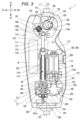
- FIG. 1 is a sectional view of an electric prosthetic leg 1.
- FIG. 3 is a cross-sectional view of the expansion/contraction device 140.
- FIG. 2 is a cross-sectional view of a main part showing a bent state of the electric prosthetic leg 1.
- FIG. FIG. 2 is a cross-sectional view of the main parts of the electric prosthetic leg 1 showing the maximum bending state. It is a sectional view of a two-way clutch.
- FIG. 3 is a perspective view of a retainer 282.
- FIGS. 2A and 2B are diagrams showing the operation of the operating mechanism 240, in which (A) is a diagram showing a state where the intermittent part 212 and the intermittent part 222 are off, and (B) is a diagram showing a state where the intermittent part 212 is off and the intermittent part 222 is on. , (C) is a diagram showing a state in which the intermittent section 212 is on and the intermittent section 222 is off. (A) is a cross-sectional view showing a state in which the interrupting portion 222 is off, and (B) is a view showing the position of the operating rod 241 at that time.
- (A) is a cross-sectional view showing a state in which the interrupting portion 222 is operated from off to on, and (B) is a view showing the position of the operating rod 241 at that time.
- (A) is a sectional view showing the normal rotation ON state of the interrupting portion 222, and (B) is a view showing the position of the operating rod 241 at that time.
- (A) is a sectional view showing the reverse ON state of the intermittent portion 222, and (B) is a view showing the position of the operating rod 241 at that time.
- (A) is a cross-sectional view showing a state in which the interrupting portion 222 is operated from on to off, and (B) is a view showing the position of the operating rod 241 at that time.
- FIG. 2 is a sectional view of an electric prosthetic leg 1 according to a second embodiment.
- 1 is a functional block diagram of an electric prosthetic leg 1.
- FIG. FIG. 3 is a diagram illustrating the motion of the human and the electric prosthetic leg during climbing (step-up motion).
- FIG. 3 is a diagram illustrating the motion of a human and an electric prosthetic leg when walking on a flat surface (a walking motion on a flat surface).
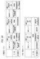
- (A) is a diagram illustrating a knee angle, (B) a thigh angle, and (C) a lower leg angle. This is a table summarizing each phase and control method of the ascending mode and the level ground/descending mode.
- 7 is a graph (comparative example) showing the load, knee angle, and states of the first intermittent mechanism 210 and the second intermittent mechanism 220 when a terminal impact occurs. It is a graph showing the load, knee angle, and states of the first intermittent mechanism 210 and the second intermittent mechanism 220 during terminal impact suppression control. It is a graph (comparative example) showing the load, the lower leg angular velocity, and the states of the first intermittent mechanism 210 and the second intermittent mechanism 220 when a jam occurs. It is a graph showing the load, the lower leg angular velocity, and the states of the first intermittent mechanism 210 and the second intermittent mechanism 220 during the jamming suppression control.
- the front-back direction, left-right direction, and up-down direction are defined based on the user of the electric prosthetic leg.
- the front of the electric prosthesis is shown as Fr, the rear as Rr, the left side as L, the right side as R, the upper side as U, and the lower side as D.
- the electric prosthetic leg 1 of this embodiment is a prosthetic leg that is attached to the leg of a person without a knee, and includes a below-knee member 110 located below the knee, and a lower-knee member 110 located below the knee.
- an above-knee member 120 that is attached to and located above the knee; a knee joint mechanism 130 that connects the below-knee member 110 and the above-knee member 120 so that the angle formed by them can be changed; and the below-knee member 110 and the above-knee member 120.
- an expansion/contraction device 200 that can expand and reduce the angle formed by the below-knee member 110 and the above-knee member 120; It includes a buffer mechanism 160 for buffering, a sensor device 270, and a battery B for supplying power to the expansion/contraction device 200 and the like.
- the above-knee member 120 includes an adapter 121 connected to a socket (not shown), and an above-knee base 126 to which the adapter 121 is attached to an upper wall 125.
- the socket is a joint member provided on the thigh, and by connecting the adapter 121 to the socket, the above-knee member 120 is integrated with the thigh.
- the below-knee member 110 includes a box-shaped main frame 111 with openings at the top and rear, side covers 112 that cover both left and right sides of the main frame 111, and a removable rear cover 113 that covers the rear opening of the main frame 111 so that it can be opened and closed. and an adapter 122 attached to the lower surface of the main frame 111.
- the above-knee member 120 is provided on the upper part of the main frame 111 of the below-knee member 110 via a connecting shaft 135 that constitutes a knee joint mechanism 130, and the adapter 122 of the main frame 111 has a leg portion extending downward. 114 are connected.
- an expansion/contraction device 200 capable of enlarging and contracting the angle formed by the below-knee member 110 and the above-knee member 120 is provided.
- the expansion/contraction device 200 is an expansion/contraction device 140 that can expand and contract the angle formed by the below-knee member 110 and the above-knee member 120 by expanding and contracting.
- the telescopic device 140 extends in the vertical direction, and as will be described in detail later, one end in the extending direction is mechanically connected to the above-knee member 120 and the other end in the extending direction is mechanically connected to the below-knee member 110. connected to.
- “mechanically connected” is a concept that includes a configuration in which the components are directly connected and a configuration in which they are connected via another member.
- the telescopic device 140 is connected to a motor M that outputs rotational power, a transmission T that transmits the power of the motor M, and a transmission T that can transmit power.
- a spindle unit SP that converts the rotational power output from the transmission into translational motion (telescopic motion); a first disconnection mechanism 210 and a second disconnection mechanism 220 provided in the transmission T; and a first disconnection mechanism 210 and a second disconnection mechanism. 220, and a control unit 10 that controls the motor M and operates the operating mechanism 240 to control the first disconnection mechanism 210 and the second disconnection mechanism 220.
- the motor M is, for example, a permanent magnet electric motor, and is arranged behind and above the transmission T, and the spindle unit SP is arranged in front of and above the transmission T.
- the spindle unit SP is arranged on the opposite side of the transmission T from the motor M on the power transmission path.
- the motor M is a gear mechanism built-in motor that includes a motor main body 171 and a gear mechanism 172 that reduces the output rotation of the motor main body 171.
- the spindle unit SP includes a spindle 173 having a male thread and a sleeve 174 having a female thread, and the rotation of the spindle 173 causes the sleeve 174 to translate along the axis of the spindle 173.
- the spindle 173 receives the rotational power of the motor M transmitted by the transmission T and performs rotational motion.
- the sleeve 174 is supported by the unit case 250 so as to be non-rotatable and movable up and down. Therefore, when the spindle 173 rotates to one side in response to the rotational power of the motor M transmitted by the transmission T, the sleeve 174 is translated away from the transmission T, and when the spindle 173 rotates to the other side, the sleeve 174 rotates to the other side. 174 is translated so as to approach the transmission T.
- translational movement of the sleeve 174 away from the transmission T is sometimes referred to as an extension operation of the spindle unit SP, and conversely, translational movement of the sleeve 174 toward the transmission T is referred to as an extension operation of the spindle unit SP. This is sometimes called a reduction operation.
- the distance between the sleeve 174 and the transmission T expands or contracts depending on the rotational direction of the spindle 173.
- the upper end of the sleeve 174 is connected to the above-knee member 120 via a link member 175.
- the below-knee member 110 and the above-knee member 120 rotate about the articulating shaft 135. This changes the angle formed by the above-knee member 120 and the below-knee member 110.
- the angle formed by the above-knee member 120 and the below-knee member 110 is defined by the first imaginary line L1 connecting the center of the connecting shaft 135 of the knee joint mechanism 130 and the adapter 121 of the above-knee member 120, and the angle between the knee joint mechanism 130 and the below-knee member 110. This is an angle defined by the center of the connecting shaft 135 and the second imaginary line L2 extending vertically downward through the below-knee member 110.
- one side of one circumference is a first angle ⁇ 1
- the other side is a second angle ⁇ 2
- the second angle ⁇ 2 is the smaller of the first angle ⁇ 1 and the second angle ⁇ 2 in the range of relative movement between the below-knee member 110 and the above-knee member 120
- the use of the electric prosthetic leg 1 The angle formed by the back side of the person's knee (back knee angle) is the second angle ⁇ 2.
- the first angle ⁇ 1 takes a value of about 175[deg] to 300[deg]
- the second angle ⁇ 2 takes a value of about 60[deg] to 185[deg].
- FIG. 3 shows a state in which the knee joint mechanism 130 is extended, and the first angle ⁇ 1 is approximately 175 [deg], and the second angle ⁇ 2 is approximately 185 [deg].
- FIG. 5 is a sectional view of a main part showing the bent state of the electric prosthetic leg 1, in which the first angle ⁇ 1 is about 240 [deg], and the second angle ⁇ 2 is about 120 [deg].
- FIG. 6 is a cross-sectional view of the main part of the electric prosthetic leg 1 showing the maximum bending state, and the first angle ⁇ 1 is about 300 [deg], and the second angle ⁇ 2 is about 60 [deg].
- the expansion/contraction device 200 of the present embodiment expands/contracts the expansion/contraction device 140 by converting the rotational movement into the expansion/contraction movement by the spindle unit SP of the expansion/contraction device 140, and accordingly the expansion/contraction between the below-knee member 110 and the above-knee member 120.
- it does not have a part that expands and contracts (moves) like the expansion and contraction device 140 (spindle unit SP), and a gear mesh is used between the below-knee member 110 and the above-knee member 120.
- a mechanism (or the like) may be provided to enlarge or reduce the angle formed by the below-knee member 110 and the above-knee member 120.
- the transmission T includes a first transmission mechanism T1 having a first transmission section that transmits the power of the motor M to the spindle unit SP at a first gear ratio;
- the second transmission mechanism T2 includes a second transmission section that transmits transmission to the spindle unit SP at a second transmission ratio different from the transmission ratio.
- the first transmission mechanism T1 and the second transmission mechanism T2 are switched between a power cutoff state and a power connection state by disconnection mechanisms 210 and 220.
- the first speed change ratio and the second speed change ratio may be different as long as they are different, and one of the first speed change mechanism T1 and the second speed change mechanism T2 may be a speed reduction mechanism and the other speed increase mechanism, or either One may be a constant velocity mechanism and the other may be a speed reduction mechanism or a speed increase mechanism, both may be a speed reduction mechanism, or both may be a speed increase mechanism.
- the first gear ratio is a rotation speed on the side opposite to the motor M (spindle This is the ratio of the rotation speed after shifting, which is the rotation speed of the unit SP side).
- the second gear ratio is a rotation speed on the side opposite to the motor M (spindle This is the ratio of the rotation speed after shifting, which is the rotation speed of the unit SP side).
- the first gear ratio of the first transmission mechanism T1 when the first gear ratio of the first transmission mechanism T1 is smaller than 1, the rotation speed on the side opposite to the motor M (spindle unit SP side) decreases compared to the rotation speed on the motor M side, and the torque increases.
- the second speed ratio of the second speed change mechanism T2 is larger than 1, the rotation speed on the side opposite to the motor M (spindle unit SP side) increases more than the rotation speed on the motor M side, and the torque decreases.
- the first speed change ratio is set to be smaller than 1
- the second speed change ratio is set to be larger than 1
- the first speed change mechanism T1 is arranged below the second speed change mechanism T2.
- the first transmission mechanism T1 and the second transmission mechanism T2 include a first shaft 181 rotatably arranged on the downward extension of the output shaft 172a of the gear mechanism section 172, and a first shaft 181 rotatably arranged on the downward extension of the spindle 173 of the spindle unit SP.
- a second shaft 182 that is rotatably arranged is included.
- the first shaft 181 is integrally rotatably connected to the output shaft 172a of the gear mechanism section 172 of the motor M via a coupling 187 that allows an axial center error.
- the second shaft 182 is integrally rotatably connected to the spindle 173 of the spindle unit SP. Note that the second shaft 182 of this embodiment is integrated with the spindle 173 of the spindle unit SP, but the second shaft 182 is connected to the spindle 173 of the spindle unit SP using spline fitting or coupling. You may.
- the first transmission mechanism T1 includes a first transmission section composed of a first drive gear 183 and a first driven gear 184 that mesh with each other.
- the first drive gear 183 is rotatably supported by the first shaft 181
- the first driven gear 184 is rotatably supported by the second shaft 182.
- the rotation axes of the first driven gear 184 and the second shaft 182 coincide with each other.
- the first transmission mechanism T1 of this embodiment is a deceleration transmission mechanism in which the first drive gear 183 has a smaller diameter than the first driven gear 184, and can extend and retract the spindle unit SP at low speed and high torque.
- the second transmission mechanism T2 includes a second transmission section composed of a second drive gear 185 and a second driven gear 186 that mesh with each other.
- the second drive gear 185 is supported by the first shaft 181 so as to be integrally rotatable, and the second driven gear 186 is supported by the second shaft 182 so as to be relatively rotatable.
- the second driven gear 186 and the second shaft 182 have the same rotational axis.
- the second transmission mechanism T2 of this embodiment is a speed increasing transmission mechanism in which the second drive gear 185 has a larger diameter than the second driven gear 186, and can extend and contract the spindle unit SP at high speed and with low torque. .
- the second transmission mechanism T2 is arranged above the first transmission mechanism T1, but the second transmission mechanism T2 may be arranged below the first transmission mechanism T1.
- the first shaft 181 and the second shaft 182 of this embodiment are each formed integrally from the beginning, it is also possible to form the upper and lower gear support parts as separate bodies and then integrally connect (combine) them. good.
- the first disconnection mechanism 210 includes a disconnection section 212 provided between the first driven gear 184 and the second shaft 182.
- the second disconnection mechanism 220 includes a disconnection section 222 provided between the second driven gear 186 and the second shaft 182.
- These intermittent parts 212 and 222 have a common configuration and can be switched between a cutoff state in which power transmission is cut off and a power transmission enabled state in which rotational power in both one direction and the other direction can be transmitted. It is composed of Note that details of the intermittent parts 212 and 222 will be described later.
- the operating mechanism 240 includes an operating rod 241 that is capable of intermittent operation of the intermittent parts 212 and 222, and a servo motor 242 that linearly moves the operating rod 241.
- the second shaft 182 is a hollow shaft having an internal space S2 extending in the rotational axis direction (also referred to as the vertical direction), and the operating rod 241 is disposed in this internal space S2.
- the operating rod 241 is provided with a rack 241a at its lower end exposed from the internal space S2.
- the operating rod 241 is supported by bearings B4 and B5 disposed in the internal space S2 so that it cannot rotate relative to the rack 241a and can move forward and backward integrally in the direction of the rotation axis.
- a lid member 188 having an insertion hole through which the operating rod 241 is inserted is screwed into the lower end of the second shaft 182 . The lid member 188 prevents foreign matter from entering the internal space S2 and facilitates replacement of the operating rod 241.
- a pinion 243 provided on an output shaft 242a of a servo motor 242 is engaged with the rack 241a, and the vertical position of the operating rod 241 is switched in accordance with the drive of the servo motor 242.
- Small diameter portions 241b1, 241b2 and large diameter portions 241c1 to 241c3, which will be described later, are formed on the outer circumference of the operating rod 241. operates the intermittent parts 212 and 222 intermittently. Note that details of the operating mechanism 240 will be described later.
- the unit case 250 includes an upper case 251, a middle case 252, and a lower case 253. These upper case 251, middle case 252, and lower case 253 are formed separately from each other.
- the upper case 251 houses the spindle unit SP.
- the space S1 formed by the middle case 252 and the lower case 253 includes the second drive gear 185 and the second driven gear 186, the first drive gear 183 and the first driven gear 184, the intermittent parts 212 and 222, and the operating mechanism 240. A portion of it is accommodated.
- the unit case 250 has a three-stage structure of an upper case 251, a middle case 252, and a lower case 253, and can not only casing the transmission T and spindle unit SP, but also unitize the telescopic device 140 including the motor M.
- the unit case 250 is attached to the main frame 111 via a bracket (not shown).
- the mechanical stop mechanism 150 includes a stopper member 151 provided on the below-knee member 110, a first contact portion 152 provided on the above-knee base 126 of the above-knee member 120, and A second contact portion 153 is provided.
- the first contact portion 152 contacts the stopper member 151, thereby preventing the knee joint mechanism 130 from bending in the opposite direction. Ru.
- the second contact portion 153 contacts the stopper member 151, so that the knee joint mechanism 130 is further bent from the maximum bending state. things are regulated. Note that while walking with the electric prosthetic leg 1, the state of maximum flexion shown in FIG. 6 does not occur.
- the buffer mechanism 160 is provided on the above-knee member 120 side, and includes a pressing portion 162 that can press the upper end of the link member 175 with the urging force of a spring 161 (for example, a compression coil spring).
- a spring 161 for example, a compression coil spring.
- a lower end portion of the link member 175 is rotatably connected to the sleeve 174 of the spindle unit SP via a first rotating portion 176, and an upper end portion of the link member 175 is connected to the above-knee member 120 via a second rotating portion 177. are rotatably connected via.
- a cam portion 178 is formed at the upper end of the link member 175.
- the cam portion 178 has a small diameter outer circumferential portion 178a having a small diameter centered on the second rotating portion 177, a large diameter outer circumferential portion 178b having a long distance from the second rotating portion 177, a small diameter outer circumferential portion 178a, and a large diameter outer circumferential portion. 178b and a connecting outer circumferential portion 178c that connects the connecting portions 178b without a step.
- the pressing portion 162 faces the small diameter outer peripheral portion 178a of the cam portion 178, so the pressing portion 162 and the cam portion 178 are separated from each other. ing.
- FIG. 3 when the knee joint mechanism 130 extends in response to the contraction operation of the spindle unit SP and approaches the mechanical stop position on the extension side, the opposing position of the pressing part 162 and the cam part 178 shifts to the connecting outer peripheral part 178c.
- the cam portion 178 moves from the cam portion to the large diameter outer peripheral portion 178b, the cam portion 178 comes into contact with the pressing portion 162, and the large diameter outer peripheral portion 178b pushes the pressing portion 162 against the biasing force of the spring 161.
- the cam portion 178 is pressed in the return direction by the urging force of the spring 161.
- the biasing force of the spring 161 acts as resistance, and the impact when the first contact portion 152 contacts the stopper member 151 is buffered.
- Each of the intermittent parts 212 and 222 has a common configuration and can be switched between a cutoff state in which power transmission is cut off and a power transmission enabled state in which rotational power in both one direction and the other direction can be transmitted.
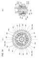
- Each disconnection section 212, 222 of this embodiment is configured using a two-way clutch 280 with a forced release function, as shown in FIG.
- the two-way clutch 280 includes a plurality of rollers 281 (three in this embodiment) disposed between the outer circumferential surface of the second shaft 182 and the inner circumferential surface of the gears 184 and 186, and a plurality of rollers 281 arranged in a predetermined manner.
- a retainer 282 held at intervals; a plurality of (three in this embodiment) pins 283 that penetrate the second shaft 182 in the radial direction and are operated by the operating mechanism 240 to a forced free position and a forced free release position; A plurality of (three in this embodiment) guides 284 are provided on the retainer 282 and define the relative rotational position of the retainer 282 with respect to the second shaft 182 when the pin 283 is in the forced free position.
- the roller 281 may be a ball or a sprag.
- the radial distance A between the outer peripheral surface of the second shaft 182 and the inner peripheral surface of the gears 184 and 186 is smaller than the diameter B of the roller 281. Further, flat portions 182a are formed on the outer peripheral portion of the second shaft 182 at predetermined intervals in the circumferential direction, and the interval A is larger than the diameter B at the center side of the flat portion 182a in the circumferential direction.
- the roller 281 meshes with the outer peripheral surface of the second shaft 182 and the inner peripheral surface of the gears 184 and 186 (engaged state).
- the shaft 182 and the gears 184 and 186 are connected to be rotatable together in two directions (forced free release state).
- the retainer 282 has a ring shape that is rotatable relative to the second shaft 182 and the gears 184, 186, and includes a plurality of roller holding parts 282a that hold the rollers 281 and a guide 284. It has a plurality of guide holding parts 282b.
- a plurality of rubber balls 282c are embedded in the outer peripheral surface of the retainer 282 at predetermined intervals in the circumferential direction. These rubber balls 282c create appropriate friction between the gears 184, 186 and the retainer 282, thereby preventing unintended idling in the forced free release state.
- the member that generates friction between the gears 184, 186 and the retainer 282 is not limited to the rubber balls 282c, but may be an O-ring.
- the pin 283 has a conical convex portion 283a on the radially outer end
- the guide 284 has a conical convex portion 283a on the radially inner end surface that fits (engages) with the convex portion 283a. It has a recess 284a.
- the operating rod 241 includes, in order from above, a first large diameter portion 241c1, a first small diameter portion 241b1, a second large diameter portion 241c2, a second small diameter portion 241b2, and a third large diameter portion 241c3. They are formed at predetermined lengths and intervals.
- the operating rod 241 is provided to be able to control the two interrupting parts 212 and 222 simultaneously, but may be provided separately for each of the interrupting parts 212 and 222.
- the intermittent parts 212 and 222 are switched by the operating mechanism 240 between a forced free state (hereinafter referred to as an OFF state) and a forced free release state (hereinafter referred to as an ON state).
- a forced free state hereinafter referred to as an OFF state
- a forced free release state hereinafter referred to as an ON state
- FIG. 11 show that the operating rod 241 is moved from a position where the second large diameter portion 241c2 pushes out the pin 283 of the interrupted portion 222 in the outer diameter direction, and the first small diameter portion 241b1 moves in the inner diameter direction of the pin 283.
- the pin 283 has already moved in the inner diameter direction, but in reality, at the timing when the second shaft 182 and the second driven gear 186 start to rotate relative to each other, the retainer 283 rotates together with the second driven gear 186.
- the guide 284 pushes the pin 283 back in the radial direction on the inclined surface of the recess 284a.
- the operating rod 241 is moved from a position where the first small diameter portion 241b1 allows the pin 283 of the interrupting portion 222 to return in the inner radial direction to a position where the first large diameter portion 241c1 becomes the pin.
- the retainer 283 is moved to the position where it is pushed out in the radial direction, the convex part 283a of the pin 283 fits into the concave part 284a of the guide 284, and the relative rotational position of the retainer 282 with respect to the second shaft 182 is adjusted by the guiding action of the pin 283 and the guide 284. is fixed in a predetermined position.
- the interrupting parts 212, 222 and the operating mechanism 240 are provided on the second shaft 182 side, but as in the second embodiment shown in FIG. 15, they are provided on the first shaft 181 side. It's okay. That is, in the electric prosthetic leg 1 of the second embodiment, the interrupting portion 212 of the first disconnecting mechanism 210 is provided between the first drive gear 183 and the first shaft 181, and the interrupting portion 222 of the second disconnecting mechanism 220 is provided between the first driving gear 183 and the first shaft 181. , are provided between the second drive gear 185 and the first shaft 181. Since the other configurations are generally the same or similar to the first embodiment, the following description will also be explained using the electric prosthetic leg 1 of the first embodiment as an example.
- the sensor device 270 includes a knee angle sensor 271 provided in the knee joint mechanism 130 (articulation shaft 135), a load sensor 272 built in the adapter 122, and a sensor device disposed near the motor M. It includes an IMU (Inertial Measurement Unit) 273 mounted on a board (not shown).
- IMU Inertial Measurement Unit
- the knee angle sensor 271 detects the knee angle ( ⁇ [deg]).
- the knee angle ( ⁇ [deg]) is the angle formed by the extension line L11 of the above-knee member 120 passing through the articulation axis 135 and the below-knee member 110, as shown in FIG. 19(A).
- the knee angle ⁇ is an angle obtained by subtracting the second angle ⁇ 2 described above from 180 [deg], and is a supplementary angle of the second angle ⁇ 2.
- the knee angle ⁇ takes a negative value
- the knee angle ⁇ takes a positive value (+deg). Take. Therefore, since the possible range of the second angle ⁇ 2 is approximately 60 [deg] to 185 [deg], the possible range of the knee angle ⁇ is approximately -5 [deg] to 120 [deg].
- the load sensor 272 detects the load applied to the electric prosthetic leg 1, in other words, the load from the user of the electric prosthetic leg 1.
- the load sensor 272 is set so that the tensile load takes a positive value and the compressive load takes a negative value. Therefore, in the loaded state where the electric prosthetic leg 1 is in contact with the ground (hereinafter sometimes referred to as the stance phase), an external load (compressive load) is applied to the electric prosthetic leg 1, so it takes a negative value, and the electric prosthetic leg 1 separates from the ground.
- the unloaded state hereinafter sometimes referred to as swing phase
- no external load is applied, but a tensile load is applied due to the own weight of the electric prosthetic leg 1, so the value is positive.
- the IMU 273 acquires 3-axis angular velocity and 3-axis acceleration. Assuming that the three axes of the orthogonal coordinate system are the X, Y, and Z axes, the IMU 273 has an X-axis angular velocity ⁇ x [deg/s], a Y-axis angular velocity ⁇ y [deg/s], and a Z-axis angular velocity ⁇ z [deg/s]. , X-axis acceleration Ax [m/s 2 ], Y-axis acceleration Ay [m/s 2 ], and Z-axis acceleration Az [m/s 2 ].
- the control unit 10 drives the electric prosthetic leg 1 in a climbing mode (to be described later) when the user walks up stairs, and drives the electric prosthetic leg 1 when the user walks on flat ground or descends the stairs. 1 is driven in a level ground/descending mode which will be described later.
- the control unit 10 receives information from the sensor device 270 and controls the electric prosthetic leg 1 in each mode. More specifically, information from the knee angle sensor 271, load sensor 272, and IMU 273 is input to the control unit 10.
- the control unit 10 acquires the knee angle ⁇ from the knee angle sensor 271 and the load from the load sensor 272, and calculates the lower leg angle ⁇ s from the 3-axis angular velocity and the 3-axis acceleration detected by the IMU 273. Further, the control unit 10 calculates the thigh angle ⁇ t from the knee angle ⁇ and the lower leg angle ⁇ s. In addition, the control unit 10 can calculate the angular velocities and angular accelerations of the knee angle ⁇ , the crus angle ⁇ s, and the thigh angle ⁇ t, as well as the accelerations of the below-knee member 110 and the above-knee member 120.
- the lower leg angle ⁇ s is defined as the relationship between the center line extending in the extending direction of the below-knee member 110 centered on the articulating shaft 135 and the vertical line VL1 passing through the articulating shaft 135, as shown in FIG. 19(C).
- the lower leg angle ⁇ s takes a negative value (-deg) when the lower knee member 110 is located in front of the vertical line VL1, and the lower leg angle ⁇ s takes a negative value (-deg) when the lower knee member 110 is located behind the vertical line VL1.
- the angle ⁇ s takes a positive value (+deg).
- the thigh angle ⁇ t is defined by the vertical line VL2 passing through the hip joint 124 of the thigh 123 to which the above-knee member 120 is attached, and the center extending in the extending direction of the above-knee member 120.
- the thigh angle ⁇ t takes a negative value (-deg) when the above-knee member 120 is in front of the vertical line VL2, and the above-knee member 120 is behind the vertical line VL2.
- Sometimes the thigh angle ⁇ t takes a positive value (+deg).
- control unit 10 controls the operating mechanism 240 (servo motor 242) that switches the first intermittent mechanism 210 and the second intermittent mechanism 220 between the cutoff state and the power transmittable state based on this information, and A motor M that outputs power for extending and bending the electric prosthetic leg 1 is controlled.
- operating mechanism 240 servo motor 242
- a motor M that outputs power for extending and bending the electric prosthetic leg 1 is controlled.
- control unit 10 includes a phase determination unit 11 that determines whether the electric prosthetic leg 1 is in the stance phase or the swing phase, and a transition from the stance phase to the swing phase and from the swing phase to the stance phase. It includes a phase transition prediction unit 12 that predicts a transition to a phase, and a motor control unit 13 that controls a motor M that expands and contracts the expansion device 140 and a servo motor 242 that drives the operating rod 241.
- the phase determination unit 11 functions as a weight transition acquisition unit that acquires that the electric prosthetic leg 1 has entered a weighted state (stance phase) and a non-weighted state (swing phase), and the phase transition prediction unit 12 , has a function as a weight acquisition unit that acquires the load applied to the electric prosthetic leg 1, or acquires a loaded state (stance phase) or a non-weighted state (swivel phase).
- the phase determination unit 11 determines that the load detected by the load sensor 272 is equal to or higher than a first threshold (for example, -90 [N]) to be in the swing leg phase, and when the load is equal to or lower than a second threshold (for example, -110 [N]), the phase is determined to be in the stance leg phase. It is determined to be a phase. In addition, the phase determination unit 11 determines that the transition from the stance phase to the swing phase has occurred when the state has been determined to be the stance phase, and when the value exceeds a first threshold value (for example, ⁇ 90 [N]).
- a first threshold for example, -90 [N]
- the state is determined to be the idle leg phase and the value becomes less than or equal to the second threshold value (for example, -110 [N])
- the second threshold value for example, -110 [N]
- the first threshold value and the second threshold value may be the same value, but it is preferable that hysteresis is provided to set them to different values. This can suppress hunting.
- the phase transition prediction unit 12 transitions from the swing phase to the stance phase based on at least one of the knee angle ⁇ , the lower leg angle ⁇ s, the angular velocity ⁇ s of the lower leg angle ⁇ s (hereinafter referred to as lower leg angular velocity ⁇ s), and the thigh angle ⁇ t. and the transition from the stance phase to the swing phase.
- the phase transition prediction unit 12 predicting state transition during walking motion, it is possible to suppress terminal impact and/or tripping, which will be described later.
- the motor control unit 13 controls the motor M to extend and contract the extension device 140 to extend and bend the electric prosthetic leg 1. Further, the motor control unit 13 controls the servo motor 242 to move the operating rod 241 to switch the first disconnection mechanism 210 and the second disconnection mechanism 220 between a disconnected state and a power transmittable state.
- the power transmission possible state there is a transmission state in which power is transmitted via the first transmission mechanism T1 (hereinafter referred to as a high torque side connection state), and a transmission state in which power is transmitted through the second transmission mechanism T2. (hereinafter referred to as the high-speed side connection state).
- the electrically powered prosthetic leg 1 configured in this way can smoothly ascend stairs, whereas conventional passive prosthetic legs equipped with a passive damper had to go up one step at a time with the non-prosthetic leg (healthy leg). It becomes possible.
- the climbing mode is the mode when the user walks as if climbing stairs.
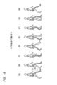
- FIG. 17 is a diagram showing the motion of the human and the electric prosthetic leg when ascending the stairs (step ascending motion)
- FIG. 21 is a graph showing the relationship between the knee angle ⁇ , the thigh angle ⁇ t, the lower leg angle ⁇ s, and the load in the step ascending mode. be.
- FIG. 17(G) is a diagram showing the transition phase from the early swing phase to the late swing phase and the late swing phase
- FIG. 17(H) is a diagram showing the transition phase from the late swing phase to the stance phase and the stance phase.
- the knee joint mechanism 130 is bent when a load is applied to the electric prosthetic leg 1 when climbing the stairs with the electric prosthetic leg 1 forward. A large amount of power is required to extend from.
- the motor control unit 13 drives the servo motor 242 to bring the first disconnection mechanism 210 and the second disconnection mechanism 220 into the high-torque side connection state (as shown in FIG. 20).
- stance phase In this high-torque side connected state, when the motor M is rotated in the extension direction, that is, in the direction that enlarges the second angle ⁇ 2, the power of the motor M is transmitted to the first shaft 181, the first drive gear 183, and the first driven gear. 184, the signal is transmitted to the disconnection section 212 of the first disconnection mechanism 210, the second shaft 182, and the spindle unit SP.
- the sleeve 174 moves to extend away from the transmission T, and the above-knee member 120 to which the sleeve 174 is connected rotates around the connecting shaft 135 relative to the below-knee member 110 to which the transmission T is attached.
- the power for this extension is the power that is made into a high torque when decelerated by the first transmission mechanism T1, so when moving the electric prosthetic leg 1 forward and climbing the stairs, a large load is applied to the electric prosthetic leg 1. Even when the knee joint mechanism 130 is bent, it is possible to reliably extend the knee joint mechanism 130 from a bent state.
- the knee joint mechanism 130 is bent from the extended state while a load is applied to the healthy leg, as shown in FIGS. There is a need. At this time, it is necessary to quickly fold the electric prosthetic leg 1 and then quickly land on the next step.
- the knee joint mechanism 130 is bent from an extended state, a large amount of power is not required, but quick action is required.
- the motor control unit 13 drives the servo motor 242 to control the first intermittent mechanism 210 and the second intermittent
- the mechanism 220 is transitioned from the high-torque side connected state to the high-speed side connected state (transition phase (stance leg ⁇ early swing leg) in FIG. 20), and during this period, the motor M is brought into a non-driving state.
- the non-driving state of the motor M means that the motor M is controlled so that no power is generated or the motor M is stopped.
- the subsequent early swing phase (early swing phase in FIG.
- the motor M in this high rotation side connected state, the motor M is rotated in the bending direction opposite to the extension direction ((E) to (G) in FIG. 17). ). Then, the power of the motor M is transmitted to the first shaft 181, the second drive gear 185, the second driven gear 186, the disconnection section 222 of the second disconnection mechanism 220, the second shaft 182, and the spindle unit SP.
- the sleeve 174 contracts so as to approach the transmission T, and the below-knee member 110 to which the transmission T is attached rotates around the connecting shaft 135 relative to the above-knee member 120 to which the sleeve 174 is connected. As a result, the knee joint mechanism 130 bends.
- the motor M is brought into a non-driving state (transition phase (early swing phase ⁇ late swing phase) in FIG. 20). Then, in the late swing phase (FIGS. 17(G) to (H)), the motor M is rotated in the extension direction in this high rotation side connected state (the late swing phase in FIG. 20). Then, the power of the motor M is transmitted to the first shaft 181, the first drive gear 183, the first driven gear 184, the disconnection section 222 of the first disconnection mechanism 210, the second shaft 182, and the spindle unit SP.
- the sleeve 174 is extended away from the transmission T, the above-knee member 120 to which the sleeve 174 is connected rotates around the connecting shaft 135, and the knee joint mechanism 130 is extended. Since the power for bending and extending the leg during the free leg is reduced in torque when the speed is increased by the second transmission mechanism T2, it is possible to quickly bend and extend the knee joint mechanism 130.
- the motor control unit 13 drives the servo motor 242 to switch the first disconnection mechanism 210 and the second disconnection mechanism 220 from the high rotation side connected state.
- a transition is made to the high torque side connected state (transition phase (late swing leg ⁇ stance leg) in FIG. 20), and the motor M is brought into a non-driving state.
- the motor control unit 13 controls the motor M, it controls the motor M based on a torque target value that is a target value of torque that is correlated to the torque that expands or contracts the angle formed by the telescoping device 140 when in the high-torque side connected state. control.
- the motor control unit 13 when the motor control unit 13 is in the high rotation side connected state, the motor control unit 13 performs control based on a position target value that is a position target value that correlates to the angle formed by the expansion and contraction device 140.
- FIG. 18 is a diagram showing the motion of the human and electric prosthetic leg when walking on level ground (level walking motion), and FIG. 22 shows the changes in knee angle ⁇ , thigh angle ⁇ t, lower leg angle ⁇ s, and load in level ground/descending mode. It is a graph showing a relationship.
- FIG. 18 (A) to (D) are the stance phase;
- FIG. 18 (D) is the transition phase from stance to swing;
- FIG. 18 (E) to (H) are the swing phase;
- ) is a diagram showing the transition phase from the swing leg to the stance leg.
- the motor M In the level ground/descending mode, the motor M is always in a non-driving state.
- the motor M is not driven, as shown in FIGS. 18A to 18D, in the stance phase in which a load is applied to the electric prosthetic leg 1, it is necessary to prevent so-called knee bending.
- the motor control unit 13 drives the servo motor 242 to bring the first disconnection mechanism 210 and the second disconnection mechanism 220 into the high rotation side connection state.
- the interrupting portion 222 is in the on state, so that the motor M and the spindle unit SP are in a power transmission state via the second transmission mechanism T2.
- the motor M is held in a non-driving state in this high-speed connected state, the external force acting on the electric prosthetic leg 1 in the bending direction is transmitted from the spindle unit SP to the motor M via the second transmission mechanism T2.
- the motor control unit 13 drives the servo motor 242 to turn the first disconnection mechanism 210 and the second disconnection mechanism 220 into the disconnected state ( Transition phase (stance leg ⁇ swing leg) in FIG. 20.
- the interrupting section 212 and the interrupting section 222 are turned off, so that the motor M and the spindle unit SP are not connected during the idle leg (idle leg phase in FIG. 20).
- the knee joint mechanism 130 is allowed to freely extend and bend. Note that the same control as walking on level ground is performed when descending stairs.
- the motor control unit 13 drives the servo motor 242 to switch the first disconnection mechanism 210 and the second disconnection mechanism 220 from the disconnected state to the high rotation side connection. state (transition phase (swing leg ⁇ stance leg) in FIG. 20).
- the control unit 10 controls the first intermittent mechanism 210 to be connected to a high-torque side connection state during the stance phase in the ascending mode, and controls the swing leg phase (early swing phase, etc.) in the ascending mode.
- the second intermittent mechanism 220 is controlled to the high rotation side connection state where it is connected.
- the control unit 10 controls the second intermittent mechanism 220 to be connected to the high rotation side connection state during the stance phase in the flat ground/descending mode, and controls the second intermittent mechanism 220 to be connected to the high rotation side connection state during the idle leg phase in the level ground/descending mode.
- the first disconnection mechanism 210 and the second disconnection mechanism 220 are controlled to a disconnection state.
- the purpose of setting the high rotation side connection state is to prevent knee bending, and it is not necessarily necessary to set the high rotation side connection state, but instead setting the high torque side connection state. You may also do so.
- the control unit 10 connects either the first intermittent mechanism 210 or the second intermittent mechanism 220 during the stance phase, which is a weighted state.
- the first connection mechanism 210 and the second disconnection mechanism 220 are controlled to be in the first connected state and the first disconnection mechanism 210 and the second disconnection mechanism 220 are disconnected during the swing phase in which no weight is applied.
- the other of the disconnecting mechanisms 220 is controlled to be in the second connected state.
- the electric prosthetic leg 1 can be operated. Improved convenience.
- the control unit 10 controls from the high torque side connection state to the high rotation side connection state, and the phase transition prediction unit When it is determined that 12 is transitioning from the swing phase to the stance phase, control is performed from the high rotation side connected state to the high torque side connected state.
- the control unit 10 controls from the high rotation side connected state to the disconnected state, and the phase transition prediction unit When it is determined that 12 is transitioning from the swing phase to the stance phase, control is performed from the cutoff state to the high rotation side connection state.
- a terminal impact is a collision between the first contact portion 152, which is a portion of the above-knee member 120 that prevents hyperextension of the electric prosthetic leg 1, and the stopper member 151, which is a portion of the below-knee member 110, during the latter half of the swinging motion of the walking motion. This is the collision sound caused by this (see Figure 3).
- the second angle ⁇ 2 (knee back angle) approximately reaches its maximum angle ( 185 [deg]), in other words, the knee angle ⁇ is set to an approximately minimum angle (-5 [deg]), but at this time, a terminal impact may occur.
- the phase determination unit 11 determines the transition from the swing phase to the stance phase, and if the connection state is switched after the determination, a terminal impact occurs. Put it away. The occurrence of a terminal impact impairs the convenience of the electric prosthetic leg 1.
- the phase transition prediction unit 12 predicts and obtains that the electric prosthetic leg 1 will transition from the swing phase to the stance phase, and the motor control unit 13 predicts that the electric prosthesis 1 will start transitioning from the swing phase to the stance phase.
- the first disconnection mechanism 210 and the second disconnection mechanism 220 are controlled to be switched from the cutoff state to the high rotation side connected state.
- the motor control unit 13 switches the first disconnection mechanism 210 and the second disconnection mechanism 220 from the disconnected state to the high rotation side connected state. control like this.
- the phase transition prediction unit 12 detects that the second angle ⁇ 2 has become equal to or greater than a threshold value smaller than the maximum angle by a predetermined angle, in other words, the knee angle ⁇ has become less than or equal to the threshold value.
- (P1) is a condition for recognizing the moment immediately before the terminal impact occurs
- (P2) and (P3) are conditions for recognizing that the person is in the middle of level walking motion (swing phase of electric prosthetic leg 1). It is. Note that the conditions (P2) and/or (P3) are not necessarily required, but by using these as determination conditions, it becomes possible to suppress the terminal impact more appropriately.
- the threshold value of the second angle ⁇ 2 is, for example, 172 [deg]. In other words, the knee angle ⁇ is 8 [deg].
- the second angle ⁇ 2 is 172 degrees or more, in other words, when the knee angle ⁇ is 8 degrees or less, the occurrence of a terminal impact can be predicted as shown in FIGS. 22 and 24.
- the first predetermined range is, for example, a negative range. That is, as described above, the thigh angle ⁇ t takes a negative value when the above-knee member 120 is located in front of the vertical line VL2 (see (B) in FIG. 19), so the electric prosthetic leg 1 is From this condition, it can be determined that the patient is swinging forward, that is, in the swing phase during walking on a flat surface (see FIG. 22).
- the second predetermined range is ⁇ 100[deg/s] or less. That is, as described above, the lower leg angle ⁇ s takes a negative value when the lower knee member 110 is located in front of the vertical line VL1 (see (C) in FIG. 19), so the lower leg angular velocity ⁇ s is -100[deg/ s] or less means that the speed at which the below-knee member 110 swings forward is fast. Since the speed at which the below-knee member 110 is swung forward is fast, it can be determined that the user is in the swing phase of walking on level ground (see FIG. 22).
- the thigh angle ⁇ t is in the negative range and , the lower leg angular velocity ⁇ s is -100 [deg/s] or less, and the phase transition prediction unit 12 detects that the knee angle ⁇ is 8 [deg] or less (the second angle ⁇ 2 is 172 [deg] or more).
- the control unit 10 predicts that the electric prosthetic leg 1 will transition from the swing phase to the stance phase, and controls the electric prosthesis 1 to switch from the cutoff state to the high rotation side connection state.
- the external force acting on the electric prosthetic leg 1 in the extension direction is transmitted from the spindle unit SP to the motor M via the second transmission mechanism T2.
- the external force in the extension direction can be attenuated by using the friction of the motor M and the transmission T, and the terminal impact is suppressed.
- control unit 10 performs control to maintain the high-speed connected state for a predetermined period of time (for example, 300 [ms]) after switching from the cutoff state to the high-speed connected state. Then, when the phase determination unit 11 acquires that the stance phase has been reached during a predetermined time period, the control unit 10 performs control to maintain the high rotation side connection state even after the predetermined time period has elapsed. In this way, by maintaining the high rotation side connection state for a predetermined period of time after switching to the high rotation side connection state, it is possible to eliminate the need for a switching operation at the time of transition to the stance phase.
- a predetermined period of time for example, 300 [ms]
- the control unit 10 switches to the cutoff state after the predetermined time period has elapsed.
- the phase determination unit 11 determines that the sensor value of the load sensor 272 has become -110 [N] or less within 300 [ms] after switching from the cutoff state to the high rotation side connection state. It is determined that the transition from the swing phase to the stance phase has occurred, and control is performed to maintain the high rotation side connection state even after 300 [ms] has elapsed.
- the electric prosthetic leg 1 is designed so that the second angle ⁇ 2 (back angle of the knee) becomes approximately the maximum angle (185 [deg]) when taking off the ground while walking on a flat surface, that is, when transitioning from the stance phase to the swing phase.
- the knee angle ⁇ is set to approximately the minimum angle (-5 [deg]), but at this time, a pinch may occur.
- the phase transition prediction unit 12 predicts and obtains that the electric prosthetic leg 1 will transition from the stance phase to the swing phase, and the motor control unit 13 predicts that the electric prosthesis 1 will start transitioning from the stance phase to the swing phase.
- the first disconnection mechanism 210 and the second disconnection mechanism 220 are controlled to be switched from the high rotation side connected state to the disconnected state.
- the motor control unit 13 when the electric prosthetic leg 1 is in the stance phase and the motor control unit 13 is controlling the first disconnection mechanism 210 and the second disconnection mechanism 220 to the high rotation side connected state, the following (Q1) is performed.
- the motor control unit 13 cuts off the first disconnection mechanism 210 and the second disconnection mechanism 220 from the high rotation side connected state. control to switch states.
- the phase transition prediction unit 12 detects that the second angle ⁇ 2 is smaller than the maximum angle by a predetermined angle than the threshold value, or in other words, the knee angle ⁇ is less than or equal to the threshold value.
- (Q1) is the condition for recognizing the moment immediately before the occurrence of a jam
- (Q2) and (Q3) are the conditions for recognizing that the person is in the middle of level walking motion (stance phase of electric prosthetic leg 1). be. Note that although the conditions (Q2) and/or (Q3) are not necessarily required, by using these as the determination conditions, it becomes possible to more appropriately suppress the jam.
- the threshold value of the second angle ⁇ 2 is, for example, 172 [deg]. In other words, the knee angle ⁇ is 8 [deg].
- the second angle ⁇ 2 is 172 [deg] or more, in other words, when the knee angle ⁇ is 8 [deg] or less, it is possible to predict the occurrence of a jam before the ground contact, as shown in FIG. 22.
- the third predetermined range is, for example, a positive range. That is, as described above, the thigh angle ⁇ t takes a positive value when the above-knee member 120 is located behind the vertical line VL2 (see (B) in FIG. 19), so the electric prosthetic leg 1 is It can be determined from this condition that when the subject remains behind, that is, in the latter half of the stance phase during flat ground walking (see FIG. 22).
- the fourth predetermined range is a range of 100 [deg/s] or more. That is, as described above, the lower leg angle ⁇ s takes a positive value when the lower knee member 110 is located behind the vertical line VL1 (see (C) in FIG. 19), so the lower leg angular velocity ⁇ s is 100[deg/s]. ] or above means that the speed at which the below-knee member 110 is swung rearward is fast. Since the speed at which the below-knee member 110 is swung rearward is fast, it can be determined that the user is in the latter half of the stance phase during level walking (see FIGS. 22 and 26).
- the thigh angle ⁇ t is in a positive range and , when the lower leg angular velocity ⁇ s is 100 [deg/s] or more and the phase transition prediction unit 12 detects that the knee angle ⁇ is 8 degrees or less (the second angle ⁇ 2 is 172 degrees or more), the control is performed.
- the unit 10 predicts that the electric prosthetic leg 1 will transition from the stance phase to the swing phase, and controls the electric prosthetic leg 1 to switch from the high rotation side connected state to the disconnected state.
- the knee joint mechanism 130 is allowed to rotate freely, so the occurrence of binding is suppressed.
- the above-described control method in the ascending mode and the level ground/descending mode can be realized by executing a program prepared in advance on a computer (processor).
- This program is stored in a computer-readable storage medium and executed by being read from the storage medium. Further, this program may be provided in a form stored in a non-transitory storage medium such as a flash memory, or may be provided via a network such as the Internet.
- a prosthetic leg device (electric prosthetic leg) applied to a knee joint is exemplified as an embodiment of a joint device in which the intermittent device of the present invention is used.
- the device may be a device (an electric prosthetic limb), the person wearing the device may be an animal other than a human, or it may be a robot.
- the below-knee member 110 of the above embodiment becomes the distal end side of the above-knee member 120, that is, the forearm.
- a first member (lower knee member 110), a second member (above-knee member 120); a connecting portion (knee joint mechanism 130) that connects the first member and the second member so that the angle formed by the second member (second angle ⁇ 2) can be changed;
- a joint device (electric prosthetic leg 1) comprising an expansion/contraction device (expansion/contraction device 200) capable of expanding and contracting the angle formed by the first member and the second member,
- the expansion/contraction device is It has a power source (motor M) and a power transmission section (transmission T) that transmits the power of the power source,
- the power transmission section is a first power transmission path (first transmission mechanism T1) that transmits the power at a first transmission ratio; a second power transmission path (second transmission mechanism T2) that transmits the power at a second transmission ratio different from the first transmission ratio;
- the expansion/contraction device is a first disconnection mechanism (first disconnection mechanism 210) that switches disconnection and connection of power in the first power transmission path; a
- the joint device improves convenience.
- a weight acquisition unit (phase transition prediction unit 12) that acquires the weight applied to the joint device, or acquires the weighted state or the non-weighted state
- the control unit includes: (a) When the weight acquisition unit acquires that the non-weighted state will transition to the weighted state, controlling to switch from the cutoff state or the second connection state to the first connection state, or (b) when the weight acquisition unit acquires that the weighted state will transition to the non-weighted state, A joint device that controls switching from the first connection state to the cutoff state or the second connection state.
- the control unit includes: (a) When the weight acquisition unit acquires that the non-weighted state will transition to the weighted state, Control is performed to switch from the cutoff state to the first connection state, The weight acquisition unit predicts and acquires a transition from the non-weighted state to the weighted state,
- the said control part is a joint device which controls switching from the said cutoff state to the said 1st connected state before starting a transition from the said unloaded state to the said loaded state.
- the weight acquisition unit predicts and acquires the transition from the non-weighted state to the weighted state, thereby enabling a smoother switching operation.
- the joint device is a first formed angle (first formed angle ⁇ 1) on one side of one circumference around the connecting axis of the connected portion, and a second formed angle (second formed angle ⁇ 2) on the other side, Among the first angle and the second angle, the second angle is defined as the smaller one in the range in which the first member and the second member move relative to each other; The second angle is set to take a value in the range from the minimum angle (60 degrees) to the maximum angle (185 degrees), The joint device is provided such that the second angle becomes approximately the maximum angle when the non-loaded state transitions to the loaded state.
- a terminal impact can occur when transitioning from a non-weighted state to a weighted state.
- a weight acquisition unit (phase transition prediction unit 12) that acquires the weight applied to the joint device, or acquires the weighted state or the non-weighted state, When the joint device is in the unloaded state and the control unit is controlling the cutoff state, When the weight acquisition unit acquires that the second angle is equal to or greater than a threshold (the second angle ⁇ 2 is 172 degrees or more), which is smaller than the maximum angle by a predetermined angle,
- the said control part is a coupling device which controls switching from the said cutoff state to the said 1st connection state.
- the coupling device When the joint device is in the unloaded state and the control unit is controlling the cutoff state, The weight acquisition unit acquires that the second angle is equal to or greater than the threshold, and A reference line (vertical When the angle formed by the line VL2) (thigh angle ⁇ t) is within the first predetermined range (minus range), The said control part is a joint device which controls switching from the said cutoff state to the said 1st connection state.
- the terminal impact can be suppressed more appropriately.
- the coupling device When the joint device is in the unloaded state and the control unit is controlling the cutoff state, The weight acquisition unit acquires that the second angle is equal to or greater than the threshold, and the angular velocity of another angle (lower leg angle ⁇ s) formed by the first member and another reference line (vertical line VL1) passing through the other rotation axis (connection shaft 135) of the first member and the second member; When (lower leg angular velocity ⁇ s) is within the second predetermined range (-100[deg/s] range), The said control part is a joint device which controls switching from the said cutoff state to the said 1st connection state.
- the terminal impact can be suppressed more appropriately.
- the joint device is a joint device which controls to maintain the said 1st connected state for a predetermined time (300 [ms]) after switching to the said 1st connected state from the said cutoff state.
- the coupling device comprising a weight transition acquisition unit (phase determination unit 11) that acquires that the joint device has entered the weighted state,
- the control unit when the weighted transition acquisition unit acquires that the weighted state has been reached during the predetermined time, A joint device that controls to maintain the first connected state even after the predetermined time has elapsed.
- the joint device includes: (b) when the weight acquisition unit acquires that the weighted state will transition to the non-weighted state, Control is performed to switch from the first connection state to the cutoff state, The weight acquisition unit predicts and acquires a transition from the weighted state to the non-weighted state,
- the said control part is a joint device which controls switching from the said 1st connected state to the said cutoff state before starting a transition from the said weighted state to the said non-loaded state.
- the weight acquisition unit predicts and acquires the transition from the weighted state to the non-weighted state, thereby making it possible to perform a smoother switching operation.
- the joint device is a first formed angle (first formed angle ⁇ 1) on one side of one circumference around the connecting axis of the connected portion, and a second formed angle (second formed angle ⁇ 2) on the other side, Among the first angle and the second angle, the second angle is defined as the smaller one in the range in which the first member and the second member move relative to each other; The second angle is set to take a value in the range from the minimum angle (60 degrees) to the maximum angle (185 degrees), The joint device is provided such that the second angle becomes approximately the maximum angle when the loaded state transitions to the non-loaded state.
- binding may occur when transitioning from a loaded state to a non-loaded state.
- the joint device according to (11), A weight acquisition unit (phase transition prediction unit 12) that acquires the weight applied to the joint device, or acquires the weighted state or the non-weighted state, When the joint device is in the loaded state and the control unit is controlling the first connected state, When the weight acquisition unit acquires that the second angle is equal to or greater than a threshold (the second angle ⁇ 2 is 172 degrees or more), which is smaller than the maximum angle by a predetermined angle, The control unit controls the coupling device to switch from the first connection state to the cutoff state.
- a threshold the second angle ⁇ 2 is 172 degrees or more
- the coupling device When the joint device is in the loaded state and the control unit is controlling the first connected state, The weight acquisition unit acquires that the second angle is equal to or greater than the threshold, and A reference line (vertical When the angle (thigh angle ⁇ t) formed with line VL2) is within the third predetermined range (positive range), The control unit controls the coupling device to switch from the first connection state to the cutoff state.
- the joint device When the joint device is in the loaded state and the control unit is controlling the first connected state, The weight acquisition unit acquires that the second angle is equal to or greater than the threshold, and the angular velocity of another angle (lower leg angle ⁇ s) formed by the first member and another reference line (vertical line VL1) passing through the other rotation axis (connection shaft 135) of the first member and the second member; When (lower leg angular velocity ⁇ s) is within the fourth predetermined range (range of 100 [deg/s] or more), The control unit controls the coupling device to switch from the first connection state to the cutoff state.
- the joint device according to any one of (1) to (14),
- the expansion/contraction device is an expansion/contraction device (expansion/contraction device 140),
- the telescoping device is One end in the extending direction is mechanically connected to the first member, the other end is mechanically connected to the second member,
- a joint device having an extensible part spindle unit SP that can expand and contract the formed angle by expanding and contracting.
- the angle formed by the expansion and contraction of the expansion and contraction part can be expanded and contracted.
- the telescopic portion is arranged on a side opposite to the power source with respect to the power transmission portion on the transmission path of the power.
- the joint device according to (15) or (16) The power source is configured to output rotational power
- the extensible portion is a joint device including a motion conversion mechanism (spindle unit SP) that converts rotational power output from the power source into translational motion.
- the extensible portion can be expanded and contracted by the motion conversion mechanism.
- the motion conversion mechanism is a joint device that includes a shaft member (spindle 173) and a cylindrical member (sleeve 174) that moves in translation along the axis of the shaft member by rotation of the shaft member.
- the motion conversion mechanism can be configured with a simple configuration.
- the coupling device is a ratio of the rotation speed after shifting to the rotation speed before shifting, which is the rotation speed on the power source side of the first transmission section in the first power transmission path
- the second speed ratio is defined as the ratio of the rotation speed after shifting to the rotation speed before shifting, which is the rotation speed on the power source side of the second transmission section in the second power transmission path
- the first gear ratio is configured to be smaller than the second gear ratio
- the control unit includes: (A) When in the loaded state, controlling the first connection state to connect the first disconnection mechanism; (B) When in the non-weighted state, A coupling device that controls the second connection state in which the second disconnection mechanism is connected.
- the joint device according to (19), The control unit further controls the power source, (A) When in the first connection state, Controlling the power source based on a torque target value that is a target value of torque that is correlated to the torque that expands or contracts the angle formed by the expansion/contraction device, (B) When in the second connection state, A joint device that controls the power source based on a position target value that is a position target value that correlates to the angle formed by the expansion/contraction device.
- the coupling device according to any one of (1) to (20),
- the first member is mounted on the mounting main body such that the first member is closer to the distal end of the mounting main body than the second member
- the joint device is a prosthetic limb device in which the connecting portion functions as a joint of the wearer.
- the coupling device according to (21), is a joint device that is a prosthesis device that is attached to the leg of the wearer.
- the joint device according to (22) or (23), The control unit includes: (B) When walking on level ground or walking down stairs, in the non-weighted state, A joint device that controls the cutoff state.
- the coupling device according to any one of (22) to (24),
- the control unit includes: (B) When walking to climb stairs, in the non-weighted state, A joint device that controls the second connected state.
- a first member (below-knee member 110); a second member (above-knee member 120); a connecting part (knee joint mechanism 130) that connects the first member and the second member so that the angle formed by the second member can be changed;
- a knee joint device (electric prosthetic leg 1) comprising an expansion/contraction device (expansion/contraction device 200) capable of expanding and contracting the angle formed by the first member and the second member,
- the expansion/contraction device is It has a power source (motor M) and a power transmission section (transmission T) that transmits the power of the power source,
- the power transmission section is a first power transmission path (first transmission mechanism T1) that transmits the power at a first transmission ratio; a second power transmission path (second transmission mechanism T2) that transmits the power at a second transmission ratio different from the first transmission ratio;
- the expansion/contraction device is a first disconnection mechanism (first disconnection mechanism 210) that switches disconnection and connection of power in the first power transmission path; a second
- the knee joint device by appropriately switching the states of the first intermittent mechanism and the second intermittent mechanism between a loaded state in which the knee joint device receives an external load and a non-loaded state in which it does not receive any external load, the knee joint device The convenience of the device is improved.
- a first member (below-knee member 110); a second member (above-knee member 120); a connecting part (knee joint mechanism 130) that connects the first member and the second member so that the angle formed by the second member can be changed;
- a method for controlling a joint device comprising an expansion/contraction device (expansion/contraction device 200) capable of expanding and contracting the angle formed by the first member and the second member,
- the expansion/contraction device is It has a power source (motor M) and a power transmission section (transmission T) that transmits the power of the power source,
- the power transmission section is a first power transmission path (first transmission mechanism T1) that transmits the power at a first transmission ratio; a second power transmission path (second transmission mechanism T2) that transmits the power at a second transmission ratio different from the first transmission ratio;
- the expansion/contraction device is a first disconnection mechanism (first disconnection mechanism 210) that switches disconnection and connection of power in the first power transmission path; further comprising a
- the joint device by appropriately switching the states of the first disconnection mechanism and the second disconnection mechanism between a loaded state in which the joint device receives an external load and a non-loaded state in which the joint device does not receive any load, the joint device Improved convenience.
- a first member (below-knee member 110); a second member (above-knee member 120); a connecting part (knee joint mechanism 130) that connects the first member and the second member so that the angle formed by the second member can be changed;
- a control program for a joint device (electric prosthetic leg 1) comprising an expansion/contraction device (expansion/contraction device 200) capable of expanding and contracting the angle formed by the first member and the second member,
- the expansion/contraction device is It has a power source (motor M) and a power transmission section (transmission T) that transmits the power of the power source,
- the power transmission section is a first power transmission path (first transmission mechanism T1) that transmits the power at a first transmission ratio; a second power transmission path (second transmission mechanism T2) that transmits the power at a second transmission ratio different from the first transmission ratio;
- the expansion/contraction device is a first disconnection mechanism (first disconnection mechanism 210) that switches disconnection and connection of power in the first power transmission path
- the joint device by appropriately switching the states of the first disconnection mechanism and the second disconnection mechanism between a loaded state in which the joint device receives an external load and a non-loaded state in which the joint device does not receive a load, the joint device Improved convenience.
- the joint device by appropriately switching the states of the first disconnection mechanism and the second disconnection mechanism between a loaded state in which the joint device receives an external load and a non-loaded state in which the joint device does not receive a load, the joint device Improved convenience.
Landscapes
- Health & Medical Sciences (AREA)
- Transplantation (AREA)
- Heart & Thoracic Surgery (AREA)
- Oral & Maxillofacial Surgery (AREA)
- Engineering & Computer Science (AREA)
- Biomedical Technology (AREA)
- Cardiology (AREA)
- Vascular Medicine (AREA)
- Life Sciences & Earth Sciences (AREA)
- Animal Behavior & Ethology (AREA)
- General Health & Medical Sciences (AREA)
- Public Health (AREA)
- Veterinary Medicine (AREA)
- Orthopedic Medicine & Surgery (AREA)
- Prostheses (AREA)
Abstract
La présente invention concerne une unité de commande (10) d'une jambe prothétique électrique (1) qui : effectue une commande pour obtenir un premier état de connexion, dans lequel l'un ou l'autre d'un premier mécanisme de connexion/déconnexion (210) ou d'un deuxième mécanisme de connexion/déconnexion (220) est connecté pendant une phase d'appui, qui est un état pondéré ; et effectue une commande pour obtenir un état de déconnexion, dans lequel le premier mécanisme de connexion/déconnexion (210) et le deuxième mécanisme de connexion/déconnexion (220) sont déconnectés ou effectue une commande pour obtenir un deuxième état de connexion, dans lequel l'autre du premier mécanisme de connexion/déconnexion (210) ou du deuxième mécanisme de connexion/déconnexion (220) est connecté, pendant une phase oscillante, qui est un état non pondéré.
Applications Claiming Priority (2)
| Application Number | Priority Date | Filing Date | Title |
|---|---|---|---|
| JP2022142465 | 2022-09-07 | ||
| JP2022-142465 | 2022-09-07 |
Publications (1)
| Publication Number | Publication Date |
|---|---|
| WO2024053688A1 true WO2024053688A1 (fr) | 2024-03-14 |
Family
ID=90191258
Family Applications (1)
| Application Number | Title | Priority Date | Filing Date |
|---|---|---|---|
| PCT/JP2023/032584 WO2024053688A1 (fr) | 2022-09-07 | 2023-09-06 | Dispositif d'articulation, dispositif d'articulation de genou, procédé de commande de dispositif d'articulation, programme de commande de dispositif d'articulation et support d'enregistrement dans lequel un programme de commande est enregistré |
Country Status (1)
| Country | Link |
|---|---|
| WO (1) | WO2024053688A1 (fr) |
Citations (10)
| Publication number | Priority date | Publication date | Assignee | Title |
|---|---|---|---|---|
| JPH05146978A (ja) * | 1991-11-27 | 1993-06-15 | Honda Motor Co Ltd | 脚式移動ロボツトの制御装置 |
| JP2006204426A (ja) * | 2005-01-26 | 2006-08-10 | Yoshiyuki Yamaumi | 装着式動作補助装置及び制御用プログラム |
| US20080288088A1 (en) * | 2007-02-06 | 2008-11-20 | Deka Products Limited Partnership | Arm prosthetic device |
| JP2013136136A (ja) * | 2011-12-27 | 2013-07-11 | Atsuo Morikawa | ロボットアーム駆動減速装置用変速装置 |
| US20150216679A1 (en) * | 2014-02-04 | 2015-08-06 | Rehabilitation Institute Of Chicago | Modular and lightweight myoelectric prosthesis components and related methods |
| WO2018092325A1 (fr) * | 2016-11-18 | 2018-05-24 | Cyberdyne株式会社 | Dispositif d'assistance au mouvement de jambe prothétique et procédé d'assistance au mouvement de jambe prothétique |
| WO2021251500A1 (fr) * | 2020-06-12 | 2021-12-16 | 本田技研工業株式会社 | Dispositif d'articulation |
| US20220202596A1 (en) * | 2019-07-02 | 2022-06-30 | Korea Labor Welfare Corporation Co., Ltd. | Hybrid-type artificial limb device and control method therefor |
| WO2022186081A1 (fr) * | 2021-03-02 | 2022-09-09 | 本田技研工業株式会社 | Dispositif d'articulation |
| WO2023113001A1 (fr) * | 2021-12-15 | 2023-06-22 | 本田技研工業株式会社 | Dispositif de transmission de puissance |
-
2023
- 2023-09-06 WO PCT/JP2023/032584 patent/WO2024053688A1/fr unknown
Patent Citations (10)
| Publication number | Priority date | Publication date | Assignee | Title |
|---|---|---|---|---|
| JPH05146978A (ja) * | 1991-11-27 | 1993-06-15 | Honda Motor Co Ltd | 脚式移動ロボツトの制御装置 |
| JP2006204426A (ja) * | 2005-01-26 | 2006-08-10 | Yoshiyuki Yamaumi | 装着式動作補助装置及び制御用プログラム |
| US20080288088A1 (en) * | 2007-02-06 | 2008-11-20 | Deka Products Limited Partnership | Arm prosthetic device |
| JP2013136136A (ja) * | 2011-12-27 | 2013-07-11 | Atsuo Morikawa | ロボットアーム駆動減速装置用変速装置 |
| US20150216679A1 (en) * | 2014-02-04 | 2015-08-06 | Rehabilitation Institute Of Chicago | Modular and lightweight myoelectric prosthesis components and related methods |
| WO2018092325A1 (fr) * | 2016-11-18 | 2018-05-24 | Cyberdyne株式会社 | Dispositif d'assistance au mouvement de jambe prothétique et procédé d'assistance au mouvement de jambe prothétique |
| US20220202596A1 (en) * | 2019-07-02 | 2022-06-30 | Korea Labor Welfare Corporation Co., Ltd. | Hybrid-type artificial limb device and control method therefor |
| WO2021251500A1 (fr) * | 2020-06-12 | 2021-12-16 | 本田技研工業株式会社 | Dispositif d'articulation |
| WO2022186081A1 (fr) * | 2021-03-02 | 2022-09-09 | 本田技研工業株式会社 | Dispositif d'articulation |
| WO2023113001A1 (fr) * | 2021-12-15 | 2023-06-22 | 本田技研工業株式会社 | Dispositif de transmission de puissance |
Similar Documents
| Publication | Publication Date | Title |
|---|---|---|
| EP3538030B1 (fr) | Jambes d'exosquelette pour réduire la fatigue pendant un accroupissement répétitif et prolongé | |
| US10966894B2 (en) | Exoskeleton legs to reduce fatigue during repetitive and prolonged squatting | |
| JP7368458B2 (ja) | 継手装置 | |
| JP2018102755A (ja) | 動作補助装置 | |
| US10531966B2 (en) | Prosthetic joints | |
| JP6791715B2 (ja) | ジョイントアセンブリ及びこれを含む運動補助装置 | |
| WO2021040039A1 (fr) | Dispositif d'articulation | |
| WO2023113001A1 (fr) | Dispositif de transmission de puissance | |
| WO2022186081A1 (fr) | Dispositif d'articulation | |
| WO2024053688A1 (fr) | Dispositif d'articulation, dispositif d'articulation de genou, procédé de commande de dispositif d'articulation, programme de commande de dispositif d'articulation et support d'enregistrement dans lequel un programme de commande est enregistré | |
| JP2014223195A (ja) | 歩行支援装置 | |
| EP2928419B1 (fr) | Prothèse d'articulation de genou | |
| EP2842522B1 (fr) | Système de prothèse de cheville commandée par un microprocesseur pour adaptation au pied et au terrain | |
| WO2024053687A1 (fr) | Dispositif de couplage, procédé de commande de dispositif de couplage, programme de commande de dispositif de couplage et support d'enregistrement sur lequel est stocké ledit programme de commande | |
| EP3995113A1 (fr) | Dispositif de membre artificiel de type hybride et sa méthode de contrôle | |
| JP2024037543A (ja) | 膝継手装置、情報処理装置、膝継手装置の情報処理方法、膝継手装置の制御プログラム、及び、該制御プログラムを記憶した記憶媒体 | |
| WO2021251500A1 (fr) | Dispositif d'articulation | |
| JP2023088641A (ja) | 動力伝達装置 | |
| WO2022087161A1 (fr) | Système d'articulation de genou et de cheville motorisé à commande adaptative | |
| CN108066109B (zh) | 一种助行机器人 | |
| JP2022133998A (ja) | 継手装置 | |
| WO2022260098A1 (fr) | Dispositif d'articulation | |
| JP2022133997A (ja) | 継手装置 | |
| WO2023112999A1 (fr) | Dispositif d'interruption et dispositif d'accouplement | |
| JP2023088643A (ja) | 動力伝達装置 |
Legal Events
| Date | Code | Title | Description |
|---|---|---|---|
| 121 | Ep: the epo has been informed by wipo that ep was designated in this application |
Ref document number: 23863226 Country of ref document: EP Kind code of ref document: A1 |