WO2024053085A1 - 電極チップ再生装置 - Google Patents
電極チップ再生装置 Download PDFInfo
- Publication number
- WO2024053085A1 WO2024053085A1 PCT/JP2022/033857 JP2022033857W WO2024053085A1 WO 2024053085 A1 WO2024053085 A1 WO 2024053085A1 JP 2022033857 W JP2022033857 W JP 2022033857W WO 2024053085 A1 WO2024053085 A1 WO 2024053085A1
- Authority
- WO
- WIPO (PCT)
- Prior art keywords
- shaping
- electrode tip
- tip
- electrode
- jig
- Prior art date
- Legal status (The legal status is an assumption and is not a legal conclusion. Google has not performed a legal analysis and makes no representation as to the accuracy of the status listed.)
- Ceased
Links
Images



Classifications
-
- B—PERFORMING OPERATIONS; TRANSPORTING
- B23—MACHINE TOOLS; METAL-WORKING NOT OTHERWISE PROVIDED FOR
- B23B—TURNING; BORING
- B23B5/00—Turning-machines or devices specially adapted for particular work; Accessories specially adapted therefor
- B23B5/16—Turning-machines or devices specially adapted for particular work; Accessories specially adapted therefor for bevelling, chamfering, or deburring the ends of bars or tubes
-
- B—PERFORMING OPERATIONS; TRANSPORTING
- B23—MACHINE TOOLS; METAL-WORKING NOT OTHERWISE PROVIDED FOR
- B23K—SOLDERING OR UNSOLDERING; WELDING; CLADDING OR PLATING BY SOLDERING OR WELDING; CUTTING BY APPLYING HEAT LOCALLY, e.g. FLAME CUTTING; WORKING BY LASER BEAM
- B23K11/00—Resistance welding; Severing by resistance heating
- B23K11/10—Spot welding; Stitch welding
- B23K11/11—Spot welding
-
- B—PERFORMING OPERATIONS; TRANSPORTING
- B23—MACHINE TOOLS; METAL-WORKING NOT OTHERWISE PROVIDED FOR
- B23K—SOLDERING OR UNSOLDERING; WELDING; CLADDING OR PLATING BY SOLDERING OR WELDING; CUTTING BY APPLYING HEAT LOCALLY, e.g. FLAME CUTTING; WORKING BY LASER BEAM
- B23K11/00—Resistance welding; Severing by resistance heating
- B23K11/30—Features relating to electrodes
-
- B—PERFORMING OPERATIONS; TRANSPORTING
- B23—MACHINE TOOLS; METAL-WORKING NOT OTHERWISE PROVIDED FOR
- B23Q—DETAILS, COMPONENTS, OR ACCESSORIES FOR MACHINE TOOLS, e.g. ARRANGEMENTS FOR COPYING OR CONTROLLING; MACHINE TOOLS IN GENERAL CHARACTERISED BY THE CONSTRUCTION OF PARTICULAR DETAILS OR COMPONENTS; COMBINATIONS OR ASSOCIATIONS OF METAL-WORKING MACHINES, NOT DIRECTED TO A PARTICULAR RESULT
- B23Q1/00—Members which are comprised in the general build-up of a form of machine, particularly relatively large fixed members
- B23Q1/70—Stationary or movable members for carrying working-spindles for attachment of tools or work
Definitions
- the present invention relates to an electrode tip regeneration device that regenerates an electrode tip by stretching out the deformed portion of the electrode tip that bulges and deforms as the number of shots in electric resistance welding increases and reshaping the tip into a regular shape.
- regeneration differs from the concept of cutting the bulging deformed part of the electrode tip into a regular shape by polishing or cutting it, and the term “regeneration” refers to stretching out the deformed part and shaping it into a regular shape. means to regenerate.
- the term "regular shape” refers to the shape of the electrode tip when it is not in use, as well as the shape of the electrode tip when it is regenerated according to the present invention. This also includes a shape that is close to, but not completely identical to, an unused electrode tip in a state in which an alloy layer of a predetermined thickness remains on the surface.
- the electrode tip attached to the welding gun and used for electric resistance welding may bulge and deform (increase in diameter) or wear out due to pressure contact with the workpiece and heat generated during electric resistance welding. This can cause the applied current distribution to become uneven, resulting in poor welding nugget quality (welding quality), and metal particles evaporated from the chip base material and workpiece plating layer due to sputtering to the tip (surface). This causes problems such as increased power consumption during electric resistance welding due to the formation of an alloy layer as a resistance layer.
- the tip dresser device shown in Patent Document 1 is provided in a holder such that the electrode is inserted under pressure into the electrode entry recess of the holder, which is rotated by a rotating member.
- a rotating blade cuts away the deformed part of the electrode tip and regenerates it into its normal shape.
- the amount of cutting of the electrode (the amount of cutting relative to the total length of the electrode tip) is 0.1 mm to 0.3 mm, and each time the electrode tip is cut, the electrode tip becomes shorter and its life is reduced, resulting in the number of welding shots.
- the cost of electric resistance welding increases, and during cutting, the rotational torque and rotational speed fluctuate due to the cutting resistance caused by the pressure of the electrode against the holder, making the amount of cutting (amount of consumption) unstable. If the number of welding shots increases, the number of welding shots will decrease, and conversely, if the amount of cutting decreases, there will be problems such as the inability to cut the electrode tip into a regular shape.
- the electrode tip shaping jig disclosed in Patent Document 2 includes a notch portion in which the outer circumferential side of the shaping chamber is cut out except for a part of the bottom surface of the shaping chamber, which has a cup-shaped inner circumferential surface into which the tip end of the electrode tip can enter; At least one at least one is provided on the circumferential surface of the shaping chamber corresponding to at least the proximal side and the distal side shaping areas assumed at the distal end of the electrode tip, and presses against the corresponding shaping areas to push the deformed portion to each side.
- Two or more shaping parts and a tip face shaping unit which is provided extending in the radial direction at the bottom of the shaping chamber, is in pressure contact with the tip end face of the electrode tip, and shaves off a part of the alloy layer formed on the tip face to shape it. and a cutting blade for cutting at least the extruded excess portion of the outer periphery of the tip of the electrode tip within the notch.
- the electrode tip shaping device on which the electrode tip shaping jig is mounted, shapes and regenerates the electrode tip into a regular shape, includes a shaping holder that pivotally supports a rotary disk that removably holds the electrode tip shaping jig; It is composed of a rotating member such as an electric motor or a rotary actuator that rotates the rotating disk at a desired rotational torque and rotational speed.
- the electrode tip When regenerating an electrode tip, for example, if the expected number of welding shots for one electrode tip is 30,000, and the electrode tip is regenerated every 20 shots, that is, if it is regenerated 1,500 times. must be set so that the cutting amount in one shaping operation (reproduction operation) is approximately 0.005 mm (5 ⁇ m) on average.
- the cutting amount of the electrode tip in an electrode tip shaping device that uses an electrode tip shaping jig that has a notch on a part of the outer periphery and a cutting blade attached to it is the cutting amount of the cutting blade relative to the tip of the electrode tip at the notch. Determined by the amount of penetration.
- the amount of biting depends on the rotational speed of the electrode tip shaping jig, the pressing force of the electrode tip against the electrode tip shaping jig, the notch width of the electrode tip shaping jig, the shaping time, etc. Among these, the pressing force, notch width, and shaping time are determined in advance and do not change during shaping.
- the driving force of the rotating member is applied directly to the shaping holder or by a gear train.
- fluctuations in rotational torque and rotational speed were unavoidable due to cutting resistance caused by the cutting blade biting into the tip of the electrode tip.
- the problem we are trying to solve is that the cutting amount is reduced due to fluctuations in rotational torque and rotational speed due to pressure contact of the electrode tip entering the shaping chamber of the electrode tip shaping jig and cutting resistance when the cutting blade bites into the electrode tip. There is a risk that the electrode tip will not be stabilized, and the life of the electrode tip will be shortened, or that it will be difficult to shape the electrode tip into a regular shape.
- Claim 1 provides a shaping section that is provided on the circumferential surface of the shaping chamber into which the electrode tip enters and that presses against a shaping area assumed at least on the distal end side and/or base end side of the electrode tip tip, and on the bottom surface of the shaping chamber.
- a cutting blade is provided in a notch formed in a part of the inner circumferential surface of the shaping chamber and is in pressure contact with the outer periphery and tip surface of the tip of the electrode tip.
- the provided electrode tip shaping jig is rotated and the deformed part of the tip of the electrode tip is pushed out by the shaping cloth and the tip face shaping part, and the excess part is cut by the cutting blade to be shaped into a regular shape and regenerated.
- An electrode chip regeneration device includes: a rotary disc having a hollow portion in the center into which an electrode chip shaping jig is inserted in a non-rotating state; a regeneration holder rotatably supporting the rotary disc; and a rotary disc.
- a rotary member connected to the rotary member and rotated at least at a predetermined number of rotations, and a flywheel coaxially provided on either the rotary disk or the rotary member, and the cutting blade cuts into the excess portion of the electrode tip.
- the main feature is that when the rotational torque fluctuates, the rotational force is supplemented by the inertia force of the flywheel, making it possible to suppress fluctuations in the rotational speed.
- the present invention can prevent the rotational speed from changing even when the rotational torque fluctuates due to pressure contact of the electrode tip entering the shaping chamber of the electrode tip shaping jig or cutting resistance when the cutting blade bites into the electrode tip. This makes it possible to shape the electrode tip with a stable amount of cutting.
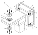
- FIG. 1 is a partially exploded perspective view schematically showing an electrode chip regeneration device.
- FIG. 3 is a schematic perspective view showing the inside of the playback head.
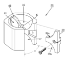
- FIG. 3 is a partially exploded perspective view of the electrode tip shaping jig.
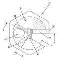
- FIG. 3 is a plan view of the electrode tip shaping jig.
- 5 is a vertical cross-sectional view taken along the line AA in FIG. 4.
- FIG. 5 is a vertical cross-sectional view taken along the line AB in FIG. 4.
- FIG. FIG. 3 is an explanatory diagram showing an electrode tip before regeneration with a deformed tip.
- a rotary disk having a hollow portion in the center into which the electrode tip shaping jig is inserted in a non-rotating state; a regeneration holder that rotatably supports the rotary disk; A rotary member that rotates at a rotational speed of In the best embodiment, the rotational force can be supplemented by the inertial force of the flywheel to suppress fluctuations in the rotational speed.
- an electrode tip regeneration device 1 is installed, for example, at the tip of an arm (not shown) of a conventionally known multi-joint electric resistance welding machine (not shown) called a so-called welding robot.
- the welding gun is placed at the movement origin position (standby position) of a conventionally known C-type or X-type welding gun (not shown).
- a C-type welding gun is configured to move toward and away from the other arm by means of an air cylinder or a numerically controllable servo motor connected to one mounting arm, for example.
- Electrode tips 7 are attached to each attachment arm so that their axes coincide with each other, facing each other, and are replaceable.
- Each electrode chip 7 is connected to a workpiece (not shown), such as a plurality of stacked galvanized steel plates, located between the two mounting arms when one mounting arm moves in a direction approaching the other mounting arm.
- a workpiece such as a plurality of stacked galvanized steel plates
- the front and back surfaces of the workpiece are clamped under a predetermined pressure, and electrical resistance welding is performed using an applied welding current.
- Each electrode tip 7 is made of copper (Cu), copper-chromium alloy (Cr-Cu), etc., which has a low electrical resistance value and is easily plastically deformed.
- the outer periphery of the tip extends in a curved shape that gradually decreases in diameter toward the tip with the required outer diameter, and the tip surface is almost flat or a curved surface with a predetermined curvature ( Figure 7 shows the case where the tip surface is flat). ) is formed.
- the support member 11 of the electrode chip regeneration device 1 is fixed to a column (not shown) provided at the movement origin position (standby position), and there are two pairs of supports (not shown) above and below the support member 11 (in this embodiment).
- Brackets 13 are provided at predetermined intervals in the vertical direction.
- a pair of left and right guide rods 15 having axes in the vertical direction are provided between the pair of brackets 13, and a slider 18 fixed to the base end of the reproducing head 17 is attached to the pair of guide rods 15 in the vertical direction. It is supported so that it can slide in the direction.
- the playback head 17 is moved, for example, to the axially intermediate portion of the guide rod 15 by the elastic force of elastic members 19 such as compression springs and rubber bushes provided on the guide rods 15 located above and below the playback head 17. be located.
- elastic members 19 such as compression springs and rubber bushes provided on the guide rods 15 located above and below the playback head 17.
- the first gear 21 has a rotating member 27 such as a step motor, an induction motor, or a rotary actuator attached to the lower side of the base end of the playback head 17, whose output shaft is coaxial with the first gear 21 and has a large diameter. and are connected via a flywheel 29 of large mass.
- the flywheel 29 may be coaxially attached to the upper part of the shaft of the first gear 21 to which the rotating member 27 is connected.
- the flywheel 29 is a member provided to compensate for the decrease in rotational speed due to an increase in rotational torque with its inertial force. It will be set accordingly.
- the flywheel 29 has a large mass, whereas when the opening width of the notch 37 is narrow and the rotational torque fluctuates little. is set on the flywheel 29 having a small mass.
- the center large diameter portion 25a of the third gear 25 has a hollow portion having a shape that can be inserted and fitted in alignment with the plane of the electrode tip shaping jig 33, and an axial length that matches the height of the electrode tip shaping jig 33. 25b is formed.
- a presser plate 31 is screwed to the upper and lower surfaces of the central large-diameter portion 25a and is fixed to the upper and lower portions of the outer peripheral surfaces of the electrode tip shaping jig 33 inserted into the hollow portion 25b. Ru.
- the electrode tip shaping jig 33 is configured as follows. As shown in FIGS. 3 to 6, the electrode tip shaping jig 33 is made of cemented carbide (high-speed steel), ceramics, etc., and has a polygonal column shape (the figure shows a hexagonal column shape) that can prevent rotation relative to the hollow portion 25b. ), and the upper and lower parts thereof have an inner diameter (inner diameter larger than the outer diameter of the electrode tip 7) into which the tip of the opposing electrode tip 7 can enter.
- Cup-shaped shaping chamber 35 (In the following explanation, since the upper and lower shaping chambers 35 are vertically mirror symmetrical, only the upper shaping chamber 35 will be explained, and the explanation of the lower shaping chamber 35 will be omitted. ) are provided mirror-symmetrically with respect to the axial direction.
- a notch 37 is formed on a part of the outer periphery of the electrode tip shaping jig 33, extending from a position eccentric from the center of the bottom surface of each shaping chamber 35 to the outer periphery, leaving the center of the bottom surface open at a predetermined angle a. .
- the opening angle of the notch 37 determines the amount of cutting of the stretched surplus portion (referred to as a kiriko or scarf), which will be described later. This is one element and is determined according to the outer diameter of the tip of the electrode tip 7 and the shape of the tip surface. That is, when the tip of the electrode tip 7 has a large diameter, the opening angle is set wide, and conversely, when the tip has a small diameter, the opening angle is set narrow. The range is set to .
- the notch surface 37a of the notch 37 located on the upper side in the rotational direction has a cutting blade 39 made of, for example, high-speed steel, cemented carbide, ceramics, etc., and the end surface on the lower side in the rotational direction of the blade 39a has an electrode tip. It is screwed so as to coincide with the center line of the shaping jig 33.
- the cutting blade 39 mainly cuts the tip of the electrode tip 7 into the first shaping section 43 (described later) at a timing slightly delayed from the timing at which the tip end surface of the electrode tip 7 that has entered the shaping chamber 35 is regenerated into a normal shape by the tip end surface shaping section 37.
- the surplus portion stretched toward the distal end side and a portion of the remaining alloy layer generated on the distal end surface and cut by the distal end surface shaping section 47 are cut off.
- a cutting waste discharge hole 41 is formed in the inner peripheral surface of the shaping chamber 35 on the opposite side to the notch 37, extending in the axial direction of the electrode tip shaping jig 33 and penetrating the partition wall of each shaping chamber 35. Ru.
- a first shaping portion 43 is formed on the inner circumferential surface of the shaping chamber 35 on the upper side of the cutting waste discharge hole 41 in the rotational direction so that the radius of curvature of the ridge line matches the radius of curvature of the shaping region on the distal end side. Ru. When regenerating the electrode tips 7 and 9, the first shaping section 43 comes into pressure contact with the distal end side shaping region and stretches the deformed portion toward the distal end surface side.
- a second shaping section 45 is formed on the inner circumferential surface of the shaping chamber 35 on the downstream side of the cutting waste discharge hole 41 in the rotational direction so that the radius of curvature of its ridge line matches the radius of curvature of the proximal shaping region. be done.
- the second shaping section 45 comes into pressure contact with the proximal side reshaping region and stretches the deformed portion toward the proximal side.
- a distal end face shaping section 47 is formed on the bottom surface of the shaping chamber 35 so as to curve and extend in the radial direction (direction orthogonal to the axis) at a location deviated from the rotation center.
- the upper surface of the distal end surface shaping portion 47 is formed into a curved surface or a flat surface corresponding to the distal end surface of the regular electrode tip 7.
- the tip surface shaping section 47 is in pressure contact with the tip surface of the electrode tip 7 entering the shaping chamber 35, and when the workpiece is a galvanized steel plate, for example, chromium-zinc (YCr) generated on the tip surface by electric resistance welding is applied. - Of the alloy layers (YCr-Zn layer, Fe -Zn layer) and regenerate it into the desired curved or flat surface.
- YCr chromium-zinc
- the electrode tip shaping jig 33 is described in detail in Patent Document 2, the configuration of the electrode tip shaping jig 33 will be cited below. Note that the reference numerals attached to the cited electrode tip shaping jig and the numerals attached to the present application are different, so please refer to them interchangeably.
- the electrode tip shaping jig 11 is made of cemented carbide (high-speed steel), ceramics, etc., and has a polygonal column shape (the figure shows a hexagonal column shape) that is inserted into the mounting hole 13a of the rotary disk 13 so as to prevent rotation.
- the shape is not limited to this shape.
- the upper and lower parts have an inner diameter (from the outer diameter of the electrode tips 7 and 9) into which the tips of the opposing electrode tips 7 and 9 can enter.
- Cup-shaped treatment chambers 25 and 27 large inner diameter (in the following explanation, since the upper and lower treatment chambers are mirror-symmetrical, only the upper treatment chamber will be explained, and the one attached to the lower treatment chamber will be explained below). ) are provided mirror-symmetrically with respect to the axial direction.Furthermore, the electrode tip shaping jig 11 is rotated, for example, in the clockwise direction as shown in the figure, as the electric motor rotates.
- a notch 29 is formed on a part of the outer periphery of the electrode tip shaping jig 11, extending from a position eccentric from the center of the bottom of each shaping chamber 25, 27 to the outer periphery, and opening at a predetermined angle, leaving the center of the bottom.
- Ru A locking recess 29b is formed in the center of the notch surface 29a located on the upper side in the rotational direction of the notch 29 (at the partition wall of each shaping chamber 25, 27), and a screw is inserted into the locking recess 29b.
- a hole 29c is formed.
- a cutting waste discharge hole 31 is formed on the inner peripheral surface of the shaping chambers 25 and 27 on the opposite side to the notch 27, extending in the axial direction of the electrode tip shaping jig 11 and penetrating the partition between the two. be done.
- a first shaping part 33 is formed on the inner peripheral surfaces of the shaping chambers 25 and 27 corresponding to the upper side of the cutting waste discharge hole 31 in the rotational direction such that the radius of curvature of the ridgeline matches the radius of curvature of the distal shaping area a.
- a second shaping portion 35 is provided on the inner peripheral surface of the shaping chambers 25 and 27 on the downstream side of the cutting waste discharge hole 31 in the rotational direction, and the radius of curvature of the ridge line thereof matches the radius of curvature of the proximal shaping region b.
- a tip face shaping section 37 is formed so as to curve and extend in the radial direction at a location deviated from the center of rotation.
- the distal end surface shaping section 37 is formed in a curved or flat shape corresponding to the curved surface or flat surface of the distal end surface of the electrode tips 7 and 9 whose upper surfaces have regular shapes, and is formed in a curved or flat shape corresponding to the curved surface or plane of the distal end surface of the electrode tips 7 and 9 that have regular upper surfaces.
- the workpiece is a galvanized steel plate, chromium-zinc (YCr-Zn layer, BCr-Zn layer), iron-zinc alloy (Fe-
- the tip surface is curved as required while removing the harder alloy layers (YCr-Zn layer, Fe-Zn layer) and leaving only the lower hardness alloy layer (BCr-Zn layer). Shape into a surface or plane.
- a cutting blade 39 is screwed into the notch surface 29a of the notch portion 29 so that the end surface of the blade portion 39a on the lower side in the rotational direction is along the center line of the electrode tip shaping jig 11.
- the cutting blade 39 is made of, for example, high-speed steel, cemented carbide, ceramics, etc., and matches the tip shape of the electrode tips 7 and 9, which have a regular shape on the inner peripheral surface side, excluding a part of the tip surface.
- the cutting blade 39 mainly cuts the tips of the electrode tips 7 and 9 at a timing slightly delayed from the timing when the tip surfaces of the electrode tips 7 and 9 that have entered the shaping chambers 25 and 27 come into contact with the tip surface shaping section 37 and are shaped into regular shapes. 1. The surplus portion stretched toward the distal end side and a part of the alloy layer on the distal end surface are cut by the first shaping section 33 to prevent generation of scarf pieces. ”
- Tables 1 and 2 show the relationship between rotational torque and rotational speed when the electrode tip 7 is regenerated by the shaping chamber 35 located above; Since the relationship between torque and rotation speed is almost the same, the description will be omitted.
- the electrode tip 7 regenerated by the electrode tip regeneration device 1 according to the present invention is subjected to electric resistance welding for a predetermined number of shots as shown in FIG. 7 (deformed state is shown by a solid line, and normal state is shown by a broken line) When it reaches the point, the tip is swollen and deformed due to pressure contact with the workpiece and welding heat, resulting in a larger diameter.
- the tip surface is melted and deformed by metal evaporation by metal sputtering, and an alloy layer (for example, when the workpiece is a galvanized steel plate, an alloy layer of YCr-Zn, BCr-Zn, and Fe-Zn is generated, but the alloy layer composition is determined by the workpiece and the metal material plated on its surface.) is generated.
- the alloy layer has a characteristic of having a higher electrical resistance value than the copper or copper alloy that is the base material of the electrode tips 7 and 9.
- the timing for regenerating the electrode tip 7 by the electrode chip regeneration device 1 is when multiple shots of welding work for one workpiece are completed, or when welding work for a required number of workpieces is completed. This may be done either when the welding gun 3 is returned to the movement origin position during standby until the next work is carried into the required welding position.
- the contact area with the workpiece will change, and the pressing force against the workpiece will become uneven, or The applied current value is not stabilized, and a uniform weld nugget cannot be formed between the workpieces, resulting in poor welding quality.
- the amount of cutting allowed during regeneration of the electrode tip 7 needs to be about 0.005 mm (5 ⁇ m) on average.
- the amount of cutting of the electrode tip 7 that is allowed during regeneration is mainly determined by the pressing force of the electrode tip 7 against the tip shaping jig 33, the opening width (opening angle) of the notch 37, the rotation speed, and the shaping time. .
- the pressurizing force, opening width, and shaping time can be set in advance and do not vary greatly depending on the state of the electrode tip 7 during regeneration, so the rotation speed (time) is a variable factor in the amount of cutting. It becomes important.
- the electrode tips 7 have been moved in the respective shaping chambers 35 of the electrode tip shaping jig 33, which rotates in the clockwise direction shown in the figure as the rotary member 27 is rotated, so that their axes coincide with each other at the standby position.
- the first shaping portion 43 that presses against the distal shaping region of the outer peripheral surface of the distal end of the electrode tip 7 pushes the bulged deformed portion toward the distal end. Extend and play.
- the other second shaping section 45, the tip surface shaping section 47, and the cutting blade 39 are in a non-contact state with respect to the outer periphery of the tip end of the electrode tip 7 entering, and the rotational resistance of the electrode tip shaping jig 33 is Avoiding becoming.
- the other first shaping section 43 , tip face shaping section 47 , and cutting blade 39 are in a non-contact state with respect to the outer peripheral surface of the tip end of the electrode tip 7 entering, and the electrode tip shaping jig 33 is rotated. Avoiding resistance.
- the tip surface shaping section 47 causes the electrode tip 7 to have a shape formed on the tip surface during electric resistance welding.
- the alloy layer (BCr-Zn layer) with relatively low hardness remains with a predetermined layer thickness (0.05 to 0.15 mm), Shape.
- the above-mentioned surplus portion is cut by a cutting blade 39 that approaches or contacts the outer peripheral surface of the tip of the electrode tip 7 that enters the shaping chamber 35 of the electrode tip shaping jig 33, and is discharged to the outside through the notch 29.
- the electrode tip 7 is regenerated by avoiding the occurrence of scarf or by shaping the electrode tip 7 into a regular shape so that scarf is reduced.
- the remaining alloy layer of the tip surface of the electrode tip 7 that has been shaped by the tip surface shaping section 47 is cut off by the cutting blade 39 that comes into contact with the outer circumferential side thereof.
- an alloy layer with a predetermined thickness remains on the tip surface of the electrode tip 7 in a predetermined range (1/4 to 1/2 of the diameter of the tip surface) from the center.
- the amount of cutting (scarf amount) of the surplus portion and the outer circumferential side of the alloy layer by the cutting blade 39 is determined by the pressing force of the electrode tip 7 against the electrode tip shaping jig 33, the opening width of the notch 37, the electrode tip
- the pressing force of the electrode tip 7, the opening width of the notch 37, and the shaping time are set in advance and are constant, so the electrode tip shaping is a variable factor. It depends on the rotation speed of the jig 33.
- the electrode tip shaping jig 33 rotates when the cutting blade 39 bites into the surplus part in the notch 37 or the outer periphery of the alloy layer. As the torque increases, the rotational speed decreases and the amount of cutting increases.
- the electrode tip shaping jig 33 is adjusted as shown in Table 1. Even if the rotational torque increases, the inertial force of the flywheel 29 can supplement the rotational force and prevent the rotational speed from decreasing. Thereby, the amount of cutting by the cutting blade 39 can be stabilized.
- electric motor output 750 W, pressing force: 200 kg, and opening angle: 30 degrees.
- the amount of cutting due to regeneration of the electrode tip 7 can be made to be about 0.005 mm on average.
- electric motor output 750 W
- pressing force 200 kg
- opening angle 30 degrees.
- This embodiment has a simple configuration in which the rotational driving force of the rotating member 27 is transmitted to the third gear 25 via the flywheel 29 to rotate the electrode tip shaping jig 33, thereby making it possible to cut the tip of the electrode tip 7. Even if the rotational torque fluctuates due to biting of the machining blade 39, the inertial force of the flywheel 29 complements the rotational force, suppresses fluctuations in rotational speed, and shapes the electrode tip 7 with a stable cutting amount. Can be played.
- the electrode tip regeneration device 1 in which the shaping chambers 35 are provided on both sides of the electrode tip shaping jig 33 in the axial direction, and a pair of opposing electrode tips 7 are simultaneously regenerated.
- An electrode tip shaping jig 33 provided with one shaping chamber 35 may be installed, and the electrode tips 7 may be shaped and regenerated one by one.
- Electrode chip regeneration device 7 Electrode chip 11 Support member 13 Bracket 15 Guide rod 17 Reproduction head 18 Slider 19 Elastic member 21 First gear 21a Shaft 23 Second gear 25 Third gear 25a as a rotating disk Hollow part 27 Rotating member 29 Flywheel 31 Holding plate 33 Electrode tip shaping jig 35 Shaping chamber 37 Notch part 39 Cutting blade 39a Blade part 41 Cutting waste discharge hole 43 First shaping part 45 Second shaping part 47 Tip surface shaping part
Landscapes
- Engineering & Computer Science (AREA)
- Mechanical Engineering (AREA)
- Turning (AREA)
- Resistance Welding (AREA)
- Milling Processes (AREA)
Priority Applications (2)
| Application Number | Priority Date | Filing Date | Title |
|---|---|---|---|
| JP2022554888A JP7219935B1 (ja) | 2022-09-09 | 2022-09-09 | 電極チップ再生装置 |
| PCT/JP2022/033857 WO2024053085A1 (ja) | 2022-09-09 | 2022-09-09 | 電極チップ再生装置 |
Applications Claiming Priority (1)
| Application Number | Priority Date | Filing Date | Title |
|---|---|---|---|
| PCT/JP2022/033857 WO2024053085A1 (ja) | 2022-09-09 | 2022-09-09 | 電極チップ再生装置 |
Publications (1)
| Publication Number | Publication Date |
|---|---|
| WO2024053085A1 true WO2024053085A1 (ja) | 2024-03-14 |
Family
ID=85173913
Family Applications (1)
| Application Number | Title | Priority Date | Filing Date |
|---|---|---|---|
| PCT/JP2022/033857 Ceased WO2024053085A1 (ja) | 2022-09-09 | 2022-09-09 | 電極チップ再生装置 |
Country Status (2)
| Country | Link |
|---|---|
| JP (1) | JP7219935B1 (https=) |
| WO (1) | WO2024053085A1 (https=) |
Citations (5)
| Publication number | Priority date | Publication date | Assignee | Title |
|---|---|---|---|---|
| JP2002248365A (ja) * | 2001-02-27 | 2002-09-03 | Matsushita Electric Ind Co Ltd | 粉砕装置 |
| JP2007090427A (ja) * | 2005-09-01 | 2007-04-12 | Kyokutoh Co Ltd | チップ成形機 |
| JP2009136882A (ja) * | 2007-12-03 | 2009-06-25 | Nadex Co Ltd | 電極チップ整形装置 |
| JP2015058446A (ja) * | 2013-09-18 | 2015-03-30 | トヨタ車体株式会社 | スポット溶接用チップの整形方法 |
| JP7121962B1 (ja) * | 2022-01-19 | 2022-08-19 | 有限会社Tne | 電極チップ整形治具及び電極チップ整形装置 |
-
2022
- 2022-09-09 JP JP2022554888A patent/JP7219935B1/ja active Active
- 2022-09-09 WO PCT/JP2022/033857 patent/WO2024053085A1/ja not_active Ceased
Patent Citations (5)
| Publication number | Priority date | Publication date | Assignee | Title |
|---|---|---|---|---|
| JP2002248365A (ja) * | 2001-02-27 | 2002-09-03 | Matsushita Electric Ind Co Ltd | 粉砕装置 |
| JP2007090427A (ja) * | 2005-09-01 | 2007-04-12 | Kyokutoh Co Ltd | チップ成形機 |
| JP2009136882A (ja) * | 2007-12-03 | 2009-06-25 | Nadex Co Ltd | 電極チップ整形装置 |
| JP2015058446A (ja) * | 2013-09-18 | 2015-03-30 | トヨタ車体株式会社 | スポット溶接用チップの整形方法 |
| JP7121962B1 (ja) * | 2022-01-19 | 2022-08-19 | 有限会社Tne | 電極チップ整形治具及び電極チップ整形装置 |
Also Published As
| Publication number | Publication date |
|---|---|
| JPWO2024053085A1 (https=) | 2024-03-14 |
| JP7219935B1 (ja) | 2023-02-09 |
Similar Documents
| Publication | Publication Date | Title |
|---|---|---|
| US4484053A (en) | Device for electrical discharge machining of a work in the form of a roll | |
| JP5204537B2 (ja) | 歯車を研削するための研削機械 | |
| US4471199A (en) | EDM Of a roll using segmented electrode short-circuited in the rough machine step | |
| CN112453601A (zh) | 一种金属制品内腔处理电火花机床 | |
| JP6489703B2 (ja) | 電極チップ再生具及び電極チップ再生装置 | |
| CN101795797A (zh) | 切削工具、形成切削工具的方法及制造切削工具的方法 | |
| WO2024053085A1 (ja) | 電極チップ再生装置 | |
| JP7121962B1 (ja) | 電極チップ整形治具及び電極チップ整形装置 | |
| JP5606250B2 (ja) | 亜鉛メッキ鋼板の抵抗溶接方法及び亜鉛メッキ鋼板抵抗溶接用電極チップの再生方法 | |
| JP4893906B2 (ja) | 電極チップ整形装置及び電極チップ整形工具 | |
| CN220296677U (zh) | 一种调制后滚压螺纹去除金属毛刺的装置 | |
| KR20130066953A (ko) | 아연 도금 강판의 저항용접 방법, 아연 도금 강판 저항용접용 전극 팁의 재생 방법 | |
| CN219541586U (zh) | 一种新型外螺纹全涨开滚丝机头 | |
| JP2010029883A (ja) | 溶接用電極チップの整形装置およびその整形方法 | |
| JP5170613B2 (ja) | 電極チップ再生工具及びその再生方法 | |
| JPH0994717A (ja) | バリ取り装置およびバリ取り方法 | |
| JP4333037B2 (ja) | 放電表面処理方法及び装置並びに放電表面処理用電極 | |
| JP2014151327A (ja) | 電極チップ再生具及び電極チップ再生方法 | |
| JP2013013939A (ja) | 電極チップ再生工具及びその再生方法 | |
| CN106794616A (zh) | 在行星式辊子挤出机处的内切齿的侵蚀 | |
| CN107159981A (zh) | 用于多微细孔电火花脉冲放电同步旋转加工的夹具装置 | |
| JP5131924B2 (ja) | 電極チップ再生具 | |
| CN120347233B (zh) | 一种钣金车削装置及不锈钢钣金的车削加工方法 | |
| JPH0796169B2 (ja) | ワイヤ放電加工機のワイヤ電極案内装置 | |
| CN222269529U (zh) | 一种机械加工用的外圆车削机 |
Legal Events
| Date | Code | Title | Description |
|---|---|---|---|
| ENP | Entry into the national phase |
Ref document number: 2022554888 Country of ref document: JP Kind code of ref document: A |
|
| 121 | Ep: the epo has been informed by wipo that ep was designated in this application |
Ref document number: 22958163 Country of ref document: EP Kind code of ref document: A1 |
|
| NENP | Non-entry into the national phase |
Ref country code: DE |
|
| 122 | Ep: pct application non-entry in european phase |
Ref document number: 22958163 Country of ref document: EP Kind code of ref document: A1 |